WO2023058457A1 - 表示装置、画像の表示方法および画像の表示プログラム - Google Patents
表示装置、画像の表示方法および画像の表示プログラム Download PDFInfo
- Publication number
- WO2023058457A1 WO2023058457A1 PCT/JP2022/035200 JP2022035200W WO2023058457A1 WO 2023058457 A1 WO2023058457 A1 WO 2023058457A1 JP 2022035200 W JP2022035200 W JP 2022035200W WO 2023058457 A1 WO2023058457 A1 WO 2023058457A1
- Authority
- WO
- WIPO (PCT)
- Prior art keywords
- display
- unit
- image
- user
- control
- Prior art date
- Legal status (The legal status is an assumption and is not a legal conclusion. Google has not performed a legal analysis and makes no representation as to the accuracy of the status listed.)
- Ceased
Links
Images


Classifications
-
- G—PHYSICS
- G06—COMPUTING OR CALCULATING; COUNTING
- G06F—ELECTRIC DIGITAL DATA PROCESSING
- G06F3/00—Input arrangements for transferring data to be processed into a form capable of being handled by the computer; Output arrangements for transferring data from processing unit to output unit, e.g. interface arrangements
- G06F3/01—Input arrangements or combined input and output arrangements for interaction between user and computer
- G06F3/016—Input arrangements with force or tactile feedback as computer generated output to the user
-
- G—PHYSICS
- G06—COMPUTING OR CALCULATING; COUNTING
- G06F—ELECTRIC DIGITAL DATA PROCESSING
- G06F3/00—Input arrangements for transferring data to be processed into a form capable of being handled by the computer; Output arrangements for transferring data from processing unit to output unit, e.g. interface arrangements
- G06F3/01—Input arrangements or combined input and output arrangements for interaction between user and computer
- G06F3/048—Interaction techniques based on graphical user interfaces [GUI]
- G06F3/0481—Interaction techniques based on graphical user interfaces [GUI] based on specific properties of the displayed interaction object or a metaphor-based environment, e.g. interaction with desktop elements like windows or icons, or assisted by a cursor's changing behaviour or appearance
-
- G—PHYSICS
- G06—COMPUTING OR CALCULATING; COUNTING
- G06F—ELECTRIC DIGITAL DATA PROCESSING
- G06F3/00—Input arrangements for transferring data to be processed into a form capable of being handled by the computer; Output arrangements for transferring data from processing unit to output unit, e.g. interface arrangements
- G06F3/01—Input arrangements or combined input and output arrangements for interaction between user and computer
- G06F3/048—Interaction techniques based on graphical user interfaces [GUI]
- G06F3/0484—Interaction techniques based on graphical user interfaces [GUI] for the control of specific functions or operations, e.g. selecting or manipulating an object, an image or a displayed text element, setting a parameter value or selecting a range
- G06F3/04845—Interaction techniques based on graphical user interfaces [GUI] for the control of specific functions or operations, e.g. selecting or manipulating an object, an image or a displayed text element, setting a parameter value or selecting a range for image manipulation, e.g. dragging, rotation, expansion or change of colour
-
- G—PHYSICS
- G06—COMPUTING OR CALCULATING; COUNTING
- G06F—ELECTRIC DIGITAL DATA PROCESSING
- G06F3/00—Input arrangements for transferring data to be processed into a form capable of being handled by the computer; Output arrangements for transferring data from processing unit to output unit, e.g. interface arrangements
- G06F3/01—Input arrangements or combined input and output arrangements for interaction between user and computer
- G06F3/048—Interaction techniques based on graphical user interfaces [GUI]
- G06F3/0487—Interaction techniques based on graphical user interfaces [GUI] using specific features provided by the input device, e.g. functions controlled by the rotation of a mouse with dual sensing arrangements, or of the nature of the input device, e.g. tap gestures based on pressure sensed by a digitiser
- G06F3/0488—Interaction techniques based on graphical user interfaces [GUI] using specific features provided by the input device, e.g. functions controlled by the rotation of a mouse with dual sensing arrangements, or of the nature of the input device, e.g. tap gestures based on pressure sensed by a digitiser using a touch-screen or digitiser, e.g. input of commands through traced gestures
-
- G—PHYSICS
- G06—COMPUTING OR CALCULATING; COUNTING
- G06F—ELECTRIC DIGITAL DATA PROCESSING
- G06F2203/00—Indexing scheme relating to G06F3/00 - G06F3/048
- G06F2203/048—Indexing scheme relating to G06F3/048
- G06F2203/04803—Split screen, i.e. subdividing the display area or the window area into separate subareas
Definitions
- the present disclosure relates to a display device, an image display method, and an image display program.
- Patent Document 1 a display device in which a translucent touch panel and a display panel capable of displaying various images are superimposed and arranged so that touch operations can be performed in the image display area.
- the display device described in Patent Document 1 is configured by superimposing a capacitive touch panel that shares a part of an electrode that constitutes a display element on an organic light emitting diode (OLED) panel, and displays an image. A touch operation in the area is possible.
- An OLED panel is also called an organic EL (electroluminescence) panel.
- the present disclosure relates to a display device that facilitates touch operations and allows the user to perceive the completion of a user's operation or a notification to the user even in a situation where it is difficult to constantly gaze at the screen.
- the present disclosure also relates to an image display method and a display program that enable a user to perceive a notification to the user or the like in a similar situation.
- a display device includes a display unit that is an area for displaying an image, and an area that is arranged to be tilted with respect to a virtual plane formed by the display unit, in which an image can be displayed and a touch operation can be performed.
- a display having an operation unit; and a control unit that executes display control of an image on the display. and at least second display control for causing the display unit to move from the operation unit to the display unit and display an image corresponding to the touch operation on the display unit when the user performs a touch operation on the operation unit. Execute one display control.
- this display device has a display in which the operation unit is tilted with respect to a virtual plane formed by the display unit, when the display unit is at an angle that makes it easy to see, the operation unit may be placed by the user's hand. It is arranged in an easy-to-reach position, and touch operation is easy.
- the control unit that executes display control of the display "moves and displays the notification from the display unit to the operation unit when notifying the user” or "displays a predetermined image from the operation unit to the display unit when a touch operation is performed.” Execute at least one display control of "moving and displaying”. Accordingly, in this display device, an image transition occurs across the two areas of the display section and the operation section, so that the notification to the user or the completion of the user's operation can be perceived more clearly.
- an image display method includes: a display unit that is an area for displaying an image; A method of displaying an image in a display device having a display having an operation unit as an area, wherein a first display is moved from the display unit to the operation unit when notifying a user, and the notification is displayed on the operation unit , and a second display in which, when the user performs a touch operation on the operation unit, the display unit is moved from the operation unit to the display unit and an image corresponding to the touch operation is displayed on the display unit.
- This image display method includes at least one display of "moving and displaying a notification from the display section to the operation section when notifying the user" or "moving and displaying a predetermined image from the operation section to the display section when performing a touch operation". It is something to do. As a result, since this display method causes an image transition across the two areas of the display section and the operation section, it is possible for the user to more clearly perceive the notification to the user or the completion of the user's operation.
- the image display program is arranged to be inclined with respect to a display unit, which is an area for displaying an image, and a virtual plane formed by the display unit, and image display and touch operation are performed.
- a program for displaying an image in a display device having a display having an operation unit which is a possible area wherein when notifying a user, the display unit is moved from the display unit to the operation unit and the notification is displayed on the operation unit.
- a second display in which, when the user performs a touch operation on the operation unit, the display unit is moved from the operation unit to the display unit and an image corresponding to the touch operation is displayed on the display unit.
- This image display program displays at least one of "moving and displaying a notification from the display section to the operation section when notifying the user" or "moving and displaying a predetermined image from the operation section to the display section when performing a touch operation". It is something to do. As a result, the display program causes the transition of the image across the two areas of the display unit and the operation unit, so that the user can more clearly perceive the notification to the user or the completion of the user's operation. It has become.
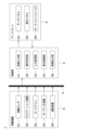
- FIG. 1 is a block diagram showing an example of a display system according to an embodiment
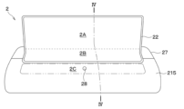
- FIG. 1 is a diagram showing an example of a display having a display section and an operation section
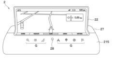
- FIG. 3 is a diagram showing an example of images displayed on a display section and an operation section of a display
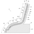
- FIG. 3 is a cross-sectional view showing a cross-sectional configuration between IV-IV of FIG. 2
- FIG. 4 is an explanatory diagram for explaining the arrangement relationship between the display section and the operation section of the display
- FIG. 4 is a diagram showing the configuration of the transparent cover of the display and the placement of the bezel
- FIG. 4 is an explanatory diagram for explaining first display control on a display
- 9 is a flow chart showing an example of a processing operation related to first display control
- FIG. 10 is a diagram showing a display example of a message section on the operation section in the first display control;
- FIG. 10 is an explanatory diagram for explaining second display control on the display;
- FIG. 10 is a diagram showing an example of touch operation of an ornament switch and image display associated therewith;
- FIG. 11 is a flow chart showing an example of a processing operation related to second display control;
- FIG. 10 is a diagram showing an example of display control associated with a touch operation on the operation unit;
- FIG. 10 is a diagram showing an example of image display when the bezel has a translucent structure;
- FIG. 10 is a diagram showing an example arrangement of actuator elements when the display includes the actuator elements;
- FIG. 10 is a diagram showing an example of image display on a display during a user's touch operation;
- FIG. 10 is a diagram showing an example of an enlarged display of an image related to content touched by a user on a display unit;
- a display system 1 to which the display device of the embodiment is applied will be described with reference to the drawings.
- the display system 1 is applied to an in-vehicle display system installed in a vehicle such as an automobile
- the application is not limited to this.
- the display system 1 is preferably used in situations where it is difficult to constantly gaze at the display 2 described later, such as in-vehicle use, but of course, it can also be used in other uses.
- FIG. 2 in order to facilitate understanding of the positional relationship between a display portion 2A, an intermediate portion 2B, and an operation portion 2C, which will be described later, of the display 2, for convenience, the rough boundary between the display portion 2A and the intermediate portion 2B is indicated by a broken line.
- the approximate outline of the portion 2C is indicated by a chain double-dashed line.
- FIG. 3 does not show a cross section, part of the image displayed on the display 2 is hatched.
- FIG. 6 the transparent cover 21 in a flat plate state is shown for convenience in order to facilitate understanding of the structure of the transparent cover 21, which will be described later.
- a display system 1 of the present embodiment includes a display 2, a control unit 3, an in-vehicle LAN 4, and an in-vehicle device 5, as shown in FIG. 1, for example.
- LAN is an abbreviation for Local Area Network.
- various signals such as video signals from the in-vehicle device 5 and output signals from the touch panel 24 mounted on the display 2 are input to the control unit 3, and the control unit 3 operates based on these signals. It is configured to execute display control of the display 2 .
- the display 2 can display images and videos corresponding to various contents based on video signals and various signals input from the in-vehicle device 5, for example, and can be touch-operated by the user. It's becoming The display 2 is configured to input/output various signals to/from the control unit 3 and to perform display control by the control unit 3 . A detailed configuration of the display 2 will be described later.
- the control unit 3 corresponds to a display control device that executes image display control on the display 2 .
- the control unit 3 is configured by a microcomputer including, for example, a CPU, ROM, RAM and I/O.
- the control unit 3 receives various signals from the display 2 and the in-vehicle device 5, reads various programs and data recorded in a recording medium (not shown) based on the signals, and executes display control of the display 2.
- the control unit 3 includes, for example, a video input unit 31 , an operation determination unit 32 , an input acquisition unit 33 , a display control unit 34 and a video output unit 35 .
- the video input unit 31 generates image data based on video signals directly from the in-vehicle device 5 or through the in-vehicle LAN 4, and outputs the data to the display control unit 34.
- the image data generated by the video input unit 31 is input to the video output unit 35 via the display control unit 34, but may be directly input to the video output unit 35.
- the operation determination unit 32 determines whether or not the user has operated the operation unit 2C of the display 2, which will be described later, based on the presence or absence of an output signal from the ornament switch 28, which will be described later, of the display 2, for example.
- the operation determination unit 32 outputs, for example, a signal corresponding to the determination result to the display control unit 34 .
- the input acquisition unit 33 acquires, for example, an input signal based on a user's touch operation on the display 2 and outputs a signal corresponding to the input signal to the display control unit 34 .
- the input acquisition unit 33 receives electrical signals associated with user's touch operations in respective regions of the display unit 2A, the intermediate unit 2B, and the operation unit 2C, which will be described later.
- the display control unit 34 executes display control on the display 2, which will be described later, based on various signals input from the video input unit 31, the operation determination unit 32, and the input acquisition unit 33, for example. For example, when executing display control, the display control unit 34 corrects the image data from the video input unit 31 and outputs the corrected image data.
- the video output unit 35 outputs video signals corresponding to various images to the display 2, for example.
- the video output unit 35 outputs a video signal corresponding to the image data corrected by the display control unit 34 when display control is executed, and an image generated by the video input unit 31 when display control is not executed.
- a video signal corresponding to the data is output to the display 2 . Details of display control by the control unit 3 will be described later.
- the in-vehicle LAN 4 is an in-vehicle communication bus that is installed in the vehicle on which the display system 1 is installed (hereinafter simply referred to as "own vehicle") and connects the control unit 3 and the in-vehicle device 5. Enables communication with device 5.
- the in-vehicle device 5 is composed of various electronic devices and sensors for inputting various signals such as video signals and vehicle information of the own vehicle to the control unit 3 .
- the in-vehicle device 5 includes, for example, an in-vehicle sensor 51, a navigation device 52, a car air conditioner 53, an audio device 54, a communication device 55, and the like, as shown in FIG. 1, but is not limited to these.
- the in-vehicle device 5 may include other in-vehicle electronic devices such as a vehicle ECU, or may include only a part of the above, in addition to the above, and the configuration thereof may be changed as appropriate. can be
- the in-vehicle sensor 51 is, for example, a temperature sensor, an illuminance sensor, a gyro sensor, a pressure sensor, an ultrasonic sensor, or any other sensor that outputs an electrical signal corresponding to an applied physical quantity, but is not limited to these. do not have.
- the navigation device 52 for example, based on the map information recorded in the map database, the current position of the own vehicle and the image of the map, and based on the user's operation, for example, destination setting, vehicle surroundings, facilities and shops around the destination A video signal indicating a video or the like related to information is input to the control section 3 .
- the navigation device 52 can acquire information about the latitude, longitude, current time, and direction of the vehicle by using a known GPS, and input this information to the control unit 3 .
- GPS is an abbreviation for Global Positioning System.
- the car air conditioner 53 is, for example, an air conditioner used for air conditioning control of the own vehicle, and inputs a video signal corresponding to a video regarding a set temperature and an air volume based on user's operation.
- the audio device 54 records, for example, music, voice, and data related thereto, and inputs a video signal corresponding to the data to the control section 3 .
- the communication device 55 for example, communicates with an external network such as the Internet by wireless communication, acquires various kinds of information, and inputs the acquired information and a video signal corresponding thereto to the control unit 3 .
- the in-vehicle device 5 inputs various signals to the control unit 3 via the in-vehicle LAN 4, the configuration is not limited to this, and various signals and the like may be directly input to the control unit 3. .
- the above is the basic configuration of the display system 1.
- the display system 1 has a display 2 which will be described below, so that touch operations are easy, and display control is performed by the control unit 3, so that even if the user is not looking at the display 2, the user can be notified, etc. It is possible to perceive the user's operation completion.
- "not gazing at the display 2" means a situation where the user does not gaze at the display 2 but the display 2 exists in the user's peripheral visual field.
- the display 2 includes a housing 27 and a bezel 22 surrounding a portion of the housing 27, as shown in FIG. 2, for example.
- the regions surrounded by the bezel 22 are the display portion 2A and the intermediate portion 2B, and the partial region outside the bezel 22 and adjacent to the intermediate portion 2B is the operating portion 2C.
- the display 2 can display various images in any of the display section 2A, the intermediate section 2B, and the operation section 2C.
- the display 2 further has a transparent cover 21, an optical adhesive layer 23, a touch panel 24, a display panel 25 and a back adhesive layer 26, as shown in FIG. 4, for example.
- the touch panel 24 and the display panel 25 are laminated in this order on the other surface 21b of the transparent cover 21 on the housing 27 side.
- the other surface 21b of the transparent cover 21 and the display panel 25 are attached to the housing 27 by the back surface adhesive layer 26, and the transparent cover 21 has a planar portion and a curved portion following the housing 27. It has a three-dimensional shape.
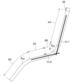
- the display section 2A, the intermediate section 2B, the operation section 2C, and the curvature changing section 2D are positioned in this order from the upper end to the lower end. ing.
- the display unit 2A is, for example, in a substantially planar state, and is an area that mainly displays content images, videos, etc. corresponding to various electronic devices to which the display 2 is connected.
- the intermediate portion 2B is an area located at a portion connecting the display portion 2A and the operation portion 2C, and is capable of displaying various images and the like like the display portion 2A.
- the operation unit 2C is located on the opposite side of the intermediate unit 2B across the bezel 22. At least icons G corresponding to various electronic devices to which the display 2 is connected are displayed, and the user touches the display position of the icon G. This is an area that can be manipulated.
- the operation unit 2C is located outside a frame-shaped bezel 22, which will be described later, and is a region mainly used for touch operations by the user.
- the curvature changing portion 2D is a region located outside the operation portion 2C and on the side opposite to the bezel 22, and has a curved surface whose curvature radius at least partially changes.
- the display 2 has a configuration in which the display section 2A and the operation section 2C form a predetermined angle ⁇ .
- the display 2 is, for example, but not limited to, a first virtual straight line VL1 along a first virtual plane formed by the display section 2A and a second virtual plane formed by the operation section 2C.
- the angle ⁇ formed with the second imaginary straight line VL2 along the line is within the range of 110 degrees to 130 degrees. Accordingly, when the display unit 2A is at an angle that makes it easy for the user to see the display unit 2A, the operation unit 2C is arranged at a position where the user's hand can easily be placed. It is possible to achieve both the operability of the operation unit 2C.
- the operation portion 2C may be entirely planar, or only a partial region adjacent to the intermediate portion 2B may be substantially planar.
- the intermediate portion 2B is a curved portion in which the portion corresponding to the intersection of the plane formed by the display portion 2A and the plane formed by the operation portion 2C is curved most.
- the intermediate portion 2B has a curvature radius R2C of 20 mm to 30 mm at the curved portion, for example.
- the curvature changing portion 2D has a shape in which the curvature radius R 2D of the curved portion changes continuously within a range of, for example, 70 mm to 100 mm. It is configured so that it does not interfere with
- the display section 2A, the intermediate section 2B and the operation section 2C are mainly composed of one transparent cover 21, which will be described later, and one touch panel 24 and one display panel 25 attached thereto. It constitutes one surface that has properties. Further, the display section 2A, the intermediate section 2B and the operation section 2C are capable of image display and touch operation in their respective regions.
- the transparent cover 21 is a transparent member that has one surface 21a and the other surface 21b that are opposite to each other, and is made of translucent material such as resin or glass.
- the transparent cover 21 has a thickness of 1 mm or less when made of glass, and a thickness of 1 to 2 mm when made of resin, and has flexibility.
- the transparent cover 21 is attached to the housing 27 by a back adhesive layer 26, for example, and has a curved shape that follows the housing 27 and has a flat portion and a curved surface portion.
- the transparent cover 21 is provided with a projection 211 on one surface 21a, as shown in FIG. 6, for example.
- both ends in the longitudinal direction of the one surface 21a of the transparent cover 21 are hereinafter referred to as “one end 21aa” and “the other end 21ab”, respectively.
- a region from the convex portion 211 to the one end 21aa is called a “first region 212”
- a region from the convex portion 211 to the other end 21ab is called a "second region 213".
- the convex portion 211 is formed, for example, by cutting or milling one surface of the transparent base material forming the transparent cover 21 using an NC machine tool, and extends along a direction orthogonal to the longitudinal direction.
- NC is an abbreviation for Numerically Control.
- the transparent cover 21 has a configuration in which the first area 212 is located in the display section 2A and the intermediate section 2B, and the second area 213 is located in the operation section 2C and the curvature changing section 2D.
- an antireflection film 214 is attached to the first area 212
- a decorative member 215 is attached to the second area 213 via the optical adhesive layer 23, respectively.
- the transparent cover 21 has substantially the same thickness in the convex portion 211 , the first region 212 and the second region 213 .
- the depth of the first region 212 is matched to the thickness of the antireflection film 214 and the optical adhesive (not shown), and the depth of the first region 212 is matched to the thickness of the decorative member 215 and the optical adhesive layer 23. It has a configuration. As a result, the transparent cover 21 does not have a step at the boundary between the projection 211 and the first area 212 and the second area 213, so that the bezel 22 can be easily attached.
- the antireflection film 214 for example, a known antireflection film is used and attached to the first region 212 with an optical adhesive (not shown).
- the antireflection film 214 suppresses the reflection of external light in the display section 2A and the intermediate section 2B, thereby further improving the visibility of the image.
- the antireflection film 214 is covered with the bezel 22 at the edge adjacent to the projection 211 .
- the decorative member 215 uses, for example, a known decorative film, and has a transparent base material and a decorative layer (not shown) formed by printing, vapor deposition, or the like. An external appearance different from the configuration is visually recognized, and the designability of the operation portion 2C and the curvature changing portion 2D is further improved.
- the decorative member 215 has a configuration in which, in addition to an arbitrary appearance, various GUIs associated with touch operations, which are images displayed on the display panel 25, can be visually recognized.
- GUI is an abbreviation for Graphical User Interface.
- the operation unit 2C is inclined at a predetermined angle ⁇ with respect to the display unit 2A, external light reflection is likely to occur in the operation unit 2C. It is possible to suppress the deterioration of the performance, and it also plays a role of improving the visibility in the operation unit 2C.
- the decorative member 215 is configured to transmit the visible light of the display panel 25 at a transmittance of 90%, for example, but it is not limited to this. sell. Also, the decorative member 215 is covered with the bezel 22 at the end adjacent to the projection 211 .
- the bezel 22 is a frame-shaped member arranged on the one surface 21a side of the transparent cover 21, and is made of any material such as resin, metal, or a compound thereof.
- the bezel 22 surrounds the display portion 2A and the intermediate portion 2B, making it easier for the user to visually grasp the main image display areas.
- the bezel 22 is, for example, similar to the decorative member 215 and is configured to have an arbitrary external appearance such as a metallic tone.
- the bezel 22 is arranged so that a portion of the transparent cover 21 covers all the protrusions 211 and the boundaries between the protrusions 211 , the antireflection film 214 , and the decorative member 215 .
- the bezel 22 covers, in addition to the convex portion 211, the end portion of the decorative member 215 adjacent to the intermediate portion 2B and the end portion of the antireflection film 214 adjacent to the operating portion 2C, thereby separating these boundaries. It also plays a role in making it look better by making it invisible.
- the bezel 22 is attached to the transparent cover 21 with, for example, an adhesive (not shown).
- the optical adhesive layer 23 is, for example, an optical adhesive such as OCA or OCR.
- OCA is an abbreviation for Optical Clear Adhesive
- OCR is an abbreviation for Optical Clear Resin.
- the optical adhesive layer 23 is arranged, for example, closer to the transparent cover 21 than the display surface 25a of the display panel 25, which is the surface of the display panel 25 on which an image is displayed. Glue the parts together.
- the optical adhesive layer 23 is arranged, for example, between the transparent cover 21 and the antireflection film 214, the decorative member 215 and the touch panel 24, and between the touch panel 24 and the display panel 25, and bonds these members. .
- the touch panel 24 is made of, for example, ITO (indium tin oxide) or the like on a translucent and flexible transparent base material, and is laminated so that a pair of transparent electrodes are opposed to each other with an insulating layer interposed therebetween. It has a configuration.
- the touch panel 24 is a touch sensor that outputs an electric signal corresponding to a touch operation site due to a change in electrostatic capacitance caused by the proximity or contact of a dielectric such as a user's finger to a patterned transparent electrode, or deformation due to contact.
- the touch panel 24 is attached to the other surface 21 b of the transparent cover 21 with an optical adhesive (not shown), and has a curved shape following the housing 27 together with the transparent cover 21 .
- the display panel 25 is, for example, an OLED panel and has a flexible configuration.
- the display panel 25 is formed by laminating circuit wiring having thin film transistors (TFTs) and OLED elements constituting pixels in this order on a substrate made of a flexible resin material. Each pixel is driven and controlled by a TFT.
- the display panel 25 is arranged across, for example, the areas of the display section 2A, the intermediate section 2B, and the operation section 2C, and displays various images, GUI, etc. corresponding to each area.
- the display panel 25 has a plane size of 14 inches (35.56 cm) when it is desired to secure an area corresponding to a display area of 12.3 inches (31.242 cm) in the display section 2A. .
- the plane size of 14 inches is 30.94 cm wide by 17.42 cm long when the ratio of width to height is 16:9. Note that the size of the display panel 25 is not limited to the above example, and can be changed as appropriate.
- the display panel 25 is connected to a circuit board (not shown) via wiring (not shown) made of FPC or the like, and various display controls are performed.
- FPC is an abbreviation for Flexible Printed Circuits.
- the circuit board (not shown) is, for example, an electronic control unit in which a power supply circuit, cooling fan, CPU, ROM, RAM and I/O are mounted on a wiring board, and is arranged inside or outside the housing 27 .
- a circuit board (not shown) is connected to the display panel 25 by wiring (not shown) passing through an opening (not shown) in the bottom surface of a recess 273 (described later) of the housing 27 .
- the layout of circuit boards and wiring (not shown) in the display 2 is not limited to the above example, and can be changed as appropriate.
- the display panel 25 may have a flexible configuration capable of displaying various images, and is not limited to an OLED panel, and may be another display panel.
- the configuration and materials used for the OLED panel and other display panels are well known, detailed description thereof will be omitted in this specification.
- back adhesive layer 26 for example, general adhesives such as acrylic, urethane, and silicone or double-sided tape can be used.
- the back surface adhesive layer 26 is arranged on the area outside the touch panel 24 and the back surface 25b of the display panel 25 on the other surface 21b of the transparent cover 21, and bonds the housing 27 and these members.
- the housing 27 is a member having a base portion 271, a support portion 272, and a recessed portion 273, for example, as shown in FIG.
- the housing 27 is made of, for example, a metal material with high thermal conductivity such as Al (aluminum) or Mg (magnesium), an alloy material thereof, or a lightweight resin material, and releases the heat of the display panel 25 to the outside. It plays a role as a heat dissipation member.
- the housing 27 has, for example, a base portion 271 and a support portion 272 formed with a concave portion 273 that serves as a space for not interfering with the touch panel 24 and the display panel 25 attached to the transparent cover 21 .
- the bottom surface of the recessed portion 273 is flat, for example, at least in a portion located in the display portion 2A and a portion of the portion located in the operation portion 2C adjacent to the intermediate portion 2B.
- the housing 27 has a structure in which a base portion 271 supports the operation portion 2C and the curvature changing portion 2D, and a support portion 272 supports the display portion 2A and the intermediate portion 2B.
- the base portion 271 is configured such that the angle between the surface formed by the display portion 2A and the surface formed by the operation portion 2C is within the range of 110 degrees to 130 degrees. It is within the range of 110 to 130 degrees with respect to the surface.
- the base portion 271 has, for example, a curved shape in which the curvature radius of the portion that supports the curvature changing portion 2D changes continuously within the range of 70 mm to 100 mm.
- the base portion 271 has, for example, an internal space (not shown), and can be configured to accommodate various electronic components such as wiring (not shown) connected to the display panel 25 and a circuit board.
- the ornament switch 28 is, for example, an arbitrary switch member that is arranged in the area of the operation unit 2C and that outputs a signal when an operating object such as a user's finger contacts or approaches.
- the ornament switch 28 is used for outputting a signal to the control section 3 and displaying various GUIs corresponding to the ornament switch 28 on the operation section 2C when touched by the user, for example.
- the ornament switch 28 is, for example, a separate member from the touch panel 24 and arranged on the second surface of the transparent cover 21 .
- One ornament switch 28 may be arranged as shown in FIG. 2, or a plurality thereof may be arranged, and the number and arrangement thereof may be changed as appropriate.
- the display 2 may or may not be configured to allow image display and touch operation even in the curvature changing portion 2D.
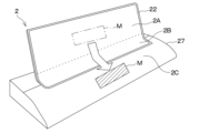
- FIG. 7 in order to facilitate understanding of the first display control described below, the outline of the message part M before the transition is indicated by a dashed line, and the outline of the message part M after the transition is indicated by a solid line. .
- the direction of movement is indicated by an outline arrow.
- the movement of the message portion M on the display 2 is indicated by a bold arrow.
- a part of the display image of the display 2 is hatched although the cross section is not shown for easy viewing.
- the first display control is executed when a notification to the user is displayed on the display section 2A of the display 2.
- the notification to the user includes, but is not limited to, information related to various contents such as the in-vehicle device 5, information that needs to be transmitted to the user such as attention or warning based on sensor signals, or information such as these. and a request for a response to
- notification display displaying a notification message regarding a request for information or a response to the user on the display section 2A or the intermediate section 2B of the display 2
- messages portion M the message portion in the display of the notification or the like in the display image
- the display section 2A side of the display 2 is called “upper”
- the operation section 2C side is called “lower”. It should be noted that the message that needs to be transmitted to the user in the notification display is not limited to the examples of the notification and request described above.
- the control unit 3 executes first display control to move the message portion M displayed on the display portion 2A or the intermediate portion 2B to the operation portion 2C when a notification or the like is displayed. do.
- a notification or the like is displayed.
- an image of the message portion M flowing downward is displayed on the display 2, and even when the display 2 is positioned in the user's peripheral vision, the user can recognize that some kind of notification has been made. becomes possible.
- FIG. 7 does not show a cross section, the message part M after the transition is hatched.
- the direction of movement of the message portion M under the first display control is indicated by an outline arrow, and the rough boundary between the display portion 2A and the intermediate portion 2B is indicated by a dashed line for convenience.
- control unit 3 reads an image display program stored in a recording medium (not shown), executes the control flow shown in FIG. 8, and executes the first display control when a predetermined condition is satisfied.
- the control unit 3 starts the process shown in FIG. 8 when a predetermined start condition is satisfied, for example, the power of the display 2 is turned on or the ignition of the vehicle is turned on.
- step S110 the control unit 3 determines whether or not a video signal or a sensor signal from the in-vehicle device 5 is input. For example, if the determination in step S110 is affirmative, the control unit 3 advances the process to step S120, and if the determination in step S110 is negative, the process advances to step S140.
- step S120 the control unit 3 determines whether or not the display is for a notification, etc. If the determination is affirmative, the process proceeds to step S130, and if the determination is negative, the process proceeds to step S140.
- the determination in step S120 may be made, for example, but not limited to, based on whether or not the various signals from the in-vehicle device 5 include a specific sensor signal or video signal.
- step S130 for example, the control section 3 executes first display control to move the message section M of the display image from the display section 2A or the intermediate section 2B to the operation section 2C.
- the message portion M transitions across the bezel 22 from the top to the bottom of the display 2, and the display 2 notifies the user even when the user does not look at the display 2.
- a video display that allows the user to recognize the fact will be performed.
- the operation portion 2C which is an operation surface on which the user's finger can easily reach and touch operation is easier than the display portion 2A of the display 2, an effect of further improving operability can be obtained.
- step S130 for example, as shown in FIG. 9, the control section 3 gives priority to the message section M for the portion of the display image located in the operation section 2C, and gives display space to the message section M. may be executed. Specifically, when a plurality of icons G (GUI) are displayed on the operation unit 2C, the control unit 3 moves the plurality of GUIs to a region that does not overlap with the message portion M transitioned from the display unit 2A. control to allow For example, as shown in FIG. 9, when the message part M has moved to the area on the right side of the operation unit 2C, the control unit 3 moves the plurality of GUIs displayed on the operation unit 2C to the left side of the operation unit 2C. Control to move to the area of .
- GUI icons G
- step S140 the control unit 3 outputs video signals corresponding to various contents from the in-vehicle device 5 or the like to the display 2 and causes the display 2 to display an image without executing the first display control.
- the display 2 performs display (hereinafter referred to as "normal display") in which the portions of the display image positioned in the display portion 2A and the intermediate portion 2B remain within these regions, for example.
- the control unit 3 repeats the above process until a predetermined end condition is met, for example, after the process of step S130 or step S140, the power of the display 2 is turned off.
- the display system 1 executes the first display control when displaying a notification, etc., so that, for example, when the user is driving the own vehicle and is gazing ahead of the own vehicle, Even so, it is possible to make the user recognize that a notification or the like is displayed on the display 2 .
- the second display control is executed when the user performs a touch operation on the operation unit 2C and feedback is given to the in-vehicle device 5 or the like.
- Examples of the feedback accompanying the touch operation include, but are not limited to, various settings related to various contents corresponding to the in-vehicle device 5, changes thereof, and completion of operations such as responses to displays such as notifications. .
- the control unit 3 controls the flow of images from the operation unit 2C to the intermediate unit 2B and the display unit 2A. Executes the second display control that occurs. As a result, an image that transitions from bottom to top is displayed on the display 2 when a touch operation is performed on the operation unit 2C. It becomes possible to recognize that the operation has been completed. Note that, in the second display control, for example, it is only necessary to display an image that transitions to the display unit 2A side across the bezel 22 starting from the portion of the operation unit 2C where the touch operation is performed. can be changed as appropriate according to the content or the like.
- the operation unit 2C includes an ornament switch 28.
- an operation body such as a finger F
- an icon G or the like related to the touched switch is displayed.
- Various GUIs are displayed.
- the operation unit 2C displays, for example, a GUI associated with the ornament switch 28 for a predetermined period of time from when the user touches the ornament switch 28, and when the predetermined period of time has elapsed, the GUI disappears. is done. Then, the user can touch the various GUIs displayed by touching the ornament switch 28 within the display time.
- the ornament switch 28 may be configured, for example, to transmit the image light of the display panel 25 to the outside while allowing the user to visually recognize a predetermined appearance such as a metallic tone, similar to the decorative member 215 . As a result, it is possible to display an image even in the area where the ornament switch 28 is arranged, and it is possible to further enhance the feeling of feedback to the user.
- control unit 3 reads an image display program stored in a recording medium (not shown) and executes the control flow shown in FIG. display control. For example, similarly to the first display control, the control unit 3 starts the processing shown in FIG. 12 when a predetermined start condition such as the power of the display 2 being turned on is satisfied.
- step S210 the control unit 3 determines whether or not a signal from the ornament switch 28 is input. For example, if the determination in step S210 is affirmative, the control unit 3 advances the process to step S220, and if the determination in step S210 is negative, the process advances to step S240.
- step S220 for example, the control unit 3 determines whether or not a touch signal is input from the position of the GUI displayed on the operation unit 2C. In the case of determination, the process proceeds to step S240.
- step S230 for example, the control unit 3 causes the operation unit 2C to display an image corresponding to the GUI displayed on the operation unit 2C and touch-operated by the user.
- a second display control is executed to display an image moving to 1A.
- the display 2 displays an image that transitions across the bezel 22 from the bottom of the display 2 to the top, starting from the position of the GUI touched by the user.
- the user can be made to recognize that feedback has been given to the system by the touch operation.
- step S230 the control unit 3 causes various GUIs such as a plurality of icons G to be displayed on the operation unit 2C, and the user performs a touch operation on one of the GUIs.
- display control to give up the display space.
- the user touches one icon G among the plurality of icons G with the finger F.
- an image G11 associated with the one icon G touched by the user is displayed, and an image in which the icons G2 other than the touched icon G are moved to the edge area so as to avoid is displayed. be.
- control unit 3 performs control to move the plurality of GUIs to an area that does not overlap the GUI touched by the user on the operation unit 2C and the related image of the GUI newly displayed by the touch operation.
- control unit 3 performs control to move the plurality of GUIs to an area that does not overlap the GUI touched by the user on the operation unit 2C and the related image of the GUI newly displayed by the touch operation.
- step S240 for example, the control unit 3 does not execute the second display control, but executes normal display in which the display 2 displays images corresponding to various contents from the in-vehicle device 5 or the like.
- the control unit 3 repeats the above processing until, for example, a predetermined termination condition such as the power of the display 2 being turned off after the processing of step S230 or step S240 is satisfied.
- a predetermined termination condition such as the power of the display 2 being turned off after the processing of step S230 or step S240 is satisfied.
- the display system 1 executes the second display control at the time of the touch operation, for example, even when the user is driving the own vehicle and looking ahead of the own vehicle. , can be made to recognize that feedback has been made by a touch operation.
- the display unit 2A, the intermediate unit 2B, and the operation unit 2C are displayed. , display the movement of the image across the areas.
- the display 2 displays a bold video transition across the inside and outside of the area surrounded by the bezel 22, and even if the user is not gazing at the display 2, the user can be notified or It is possible to recognize the feedback of operation completion.
- the display 2 since the display 2 has the display section 2A that is the main display area of the content and the operation section 2C that is mainly used as the operation area, and these are arranged at a predetermined angle, the display section 2A is arranged at a predetermined angle. It is possible to achieve both the visibility in and the ease of operation in the operation section 2C.
- the display system 1 executes an image display program corresponding to at least one of first and second display controls on a display device including a display 2, and displays an image across two areas of the display section 2A and the operation section 2C. This can also be said to be a configuration for performing an image display method that causes a transition.
- the ornament switch 28 may not be a separate member from the touch panel 24, but may be a part of the touch panel 24.
- the display 2 is controlled to display only the GUI corresponding to the ornament switch 28 on the operating section 2C, for example, before the user performs a touch operation on the operating section 2C. Then, for example, when the user touches the display position of the GUI, the display 2 is controlled to display various GUIs corresponding to the GUI around it.
- the display 2 is configured to allow touch operations similar to those of the above-described embodiment having the ornament switch 28 .
- the ornament switch 28 may not be a switch member that outputs an output signal when touched by the user's finger F or the like, but may be a decorative part attached to the decorative member 215. .
- the ornament switch 28 is attached, for example, to a portion of the decorative member 215 that is positioned above a predetermined area of the touch panel 24 with an optical adhesive or the like.
- the operation unit 2C is configured to display various associated GUIs with the ornament switch 28 as a starting point. Even with such a configuration, the display system 1 performs the same display control as when the ornament switch 28 is a switch member.
- the bezel 22 is preferably configured to transmit the light of the display panel 25 from the viewpoint of design.
- the user can visually recognize the display image of the display panel 25 even at the bezel 22, and the transition of the image across the bezel 22 in the first and second display controls is exaggerated, and the notification, etc. This has the effect of making feedback easier to recognize.
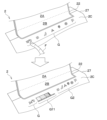
- a part of the display image is hatched although the cross section is not shown.
- the display 2 has an actuator element 29 in the operation portion 2C, and vibrates the operation surface during touch operation, thereby providing the user with an operational feeling.
- the actuator element 29 is a piezoelectric element or the like that can be bent by voltage application, and is attached to the area of the other surface 21b of the transparent cover 21 that is located at the operation portion 2C. It can be placed on both ends of the sandwich. Then, for example, when the control unit 3 detects a touch operation based on a signal from the touch panel 24, the control unit 3 drives the actuator element 29 to cause the user who is performing the touch operation to perceive vibration, thereby performing feedback control to present an operation feeling. Execute. This makes it possible to further improve the operational feeling of the operation unit 2C.
- the control unit 3 may, for example, perform display control to prevent the display image on the display 2 from becoming troublesome for the user due to the large amount of display content and character information. For example, the control unit 3 reduces or omits information other than the content displayed at that point in the display image in a normal state where a predetermined operation or selection is not required, for example, as shown in FIG. A moderate amount of display control may be implemented.
- the control unit 3 can perform display control for displaying or enlarging necessary information in a situation where a predetermined operation or selection is required.
- the type of information to be displayed on the display 2 and its priority are set in advance, and the setting data is stored in the control unit 3 or an external recording medium (not shown).
- the control unit 3 executes the above-described display control by the control unit 3, necessary information is selectively displayed in the display area of the display 2, making it easier for the user to recognize the necessary information and improving the operability of the display 2. effect to be obtained.
- the control unit 3 displays images of selections, settings, and the like in the content selected in the intermediate unit 2B or the operation unit 2C so that the user can use a wide display area. Display control can be executed to make the display larger in the unit 2A.
- the display system 1 includes, for example, an image capturing unit that captures an image of an occupant of the vehicle as the in-vehicle device 5, and determines whether or not the operator is the driver when a touch operation is performed on the display 2.
- an imaging unit such as a camera is mounted on the vehicle, and the imaging unit images at least the driver, and based on the imaging data, a known image authentication technology is used to determine whether the driver has reached out to the display 2 or not. It is configured to determine whether or not. Then, for example, the imaging unit outputs a signal corresponding to the determination result to the control unit 3, and the control unit 3 determines whether or not to execute the second display control based on the signal.
- control unit 3 is configured to perform the second display control when the operator of the display 2 is the driver, and not to perform the second display control otherwise.
- imaging unit for example, Driver Status Monitor (registered trademark) manufactured by Denso Corporation may be used, but other known imaging devices may be used.
- the display system 1 may be configured to execute at least one of the first display control and the second display control.
- the display system 1 is configured to execute only the first display control when priority is given to recognizing a notification to the user, and the second display control is performed when priority is given to recognition of touch operation feedback. is configured to execute only the display control of This also makes it possible for the user who is not gazing at the display 2 to recognize the notification or feedback.
- the controller 3 and techniques described in this disclosure are provided by configuring a processor and memory programmed to perform one or more functions embodied by a computer program. It may be implemented by a computer. Alternatively, the controller 3 and techniques described in this disclosure may be implemented by a dedicated computer provided by configuring the processor with one or more dedicated hardware logic circuits. Alternatively, the controller 3 and techniques described in this disclosure are a combination of a processor and memory programmed to perform one or more functions and a processor configured by one or more hardware logic circuits. may be implemented by one or more dedicated computers configured by The computer program may also be stored as computer-executable instructions on a computer-readable non-transitional tangible recording medium.
Landscapes
- Engineering & Computer Science (AREA)
- General Engineering & Computer Science (AREA)
- Theoretical Computer Science (AREA)
- Human Computer Interaction (AREA)
- Physics & Mathematics (AREA)
- General Physics & Mathematics (AREA)
- Controls And Circuits For Display Device (AREA)
- Position Input By Displaying (AREA)
- User Interface Of Digital Computer (AREA)
Priority Applications (2)
| Application Number | Priority Date | Filing Date | Title |
|---|---|---|---|
| CN202280067023.7A CN118056179A (zh) | 2021-10-05 | 2022-09-21 | 显示装置、图像的显示方法以及图像的显示程序 |
| US18/625,819 US12474830B2 (en) | 2021-10-05 | 2024-04-03 | Display device, image display method, and storage medium storing image display program |
Applications Claiming Priority (2)
| Application Number | Priority Date | Filing Date | Title |
|---|---|---|---|
| JP2021-164345 | 2021-10-05 | ||
| JP2021164345A JP2023055163A (ja) | 2021-10-05 | 2021-10-05 | 表示装置、画像の表示方法および画像の表示プログラム |
Related Child Applications (1)
| Application Number | Title | Priority Date | Filing Date |
|---|---|---|---|
| US18/625,819 Continuation US12474830B2 (en) | 2021-10-05 | 2024-04-03 | Display device, image display method, and storage medium storing image display program |
Publications (1)
| Publication Number | Publication Date |
|---|---|
| WO2023058457A1 true WO2023058457A1 (ja) | 2023-04-13 |
Family
ID=85804174
Family Applications (1)
| Application Number | Title | Priority Date | Filing Date |
|---|---|---|---|
| PCT/JP2022/035200 Ceased WO2023058457A1 (ja) | 2021-10-05 | 2022-09-21 | 表示装置、画像の表示方法および画像の表示プログラム |
Country Status (4)
| Country | Link |
|---|---|
| US (1) | US12474830B2 (https=) |
| JP (1) | JP2023055163A (https=) |
| CN (1) | CN118056179A (https=) |
| WO (1) | WO2023058457A1 (https=) |
Families Citing this family (1)
| Publication number | Priority date | Publication date | Assignee | Title |
|---|---|---|---|---|
| KR20250102824A (ko) * | 2023-12-28 | 2025-07-07 | 현대모비스 주식회사 | 디스플레이 모드에 따라 칵핏 레이아웃을 변경하는 방법 및 이를 적용한 칵핏 시스템 |
Citations (7)
| Publication number | Priority date | Publication date | Assignee | Title |
|---|---|---|---|---|
| JP2006007919A (ja) * | 2004-06-24 | 2006-01-12 | Mazda Motor Corp | 車両用操作ユニット |
| US20100182265A1 (en) * | 2009-01-09 | 2010-07-22 | Samsung Electronics Co., Ltd. | Mobile terminal having foldable display and operation method for the same |
| JP2015527626A (ja) * | 2012-05-22 | 2015-09-17 | サムスン エレクトロニクス カンパニー リミテッド | Ui提供方法及びそれを適用した携帯用機器 |
| JP2016126773A (ja) * | 2014-12-29 | 2016-07-11 | イマージョン コーポレーションImmersion Corporation | 視線追跡に基づく触覚効果を生成するシステム及び方法 |
| JP2016153250A (ja) * | 2015-02-20 | 2016-08-25 | クラリオン株式会社 | 情報処理装置 |
| JP2018506803A (ja) * | 2015-02-25 | 2018-03-08 | イマージョン コーポレーションImmersion Corporation | 湾曲ディスプレイとのユーザ相互作用のためのシステム及び方法 |
| CN111078091A (zh) * | 2019-11-29 | 2020-04-28 | 华为技术有限公司 | 分屏显示的处理方法、装置及电子设备 |
Family Cites Families (6)
| Publication number | Priority date | Publication date | Assignee | Title |
|---|---|---|---|---|
| US9823833B2 (en) * | 2007-06-05 | 2017-11-21 | Immersion Corporation | Method and apparatus for haptic enabled flexible touch sensitive surface |
| US8863038B2 (en) * | 2008-09-08 | 2014-10-14 | Qualcomm Incorporated | Multi-panel electronic device |
| JP2013020529A (ja) | 2011-07-13 | 2013-01-31 | Dainippon Printing Co Ltd | タッチセンサパネル部材、タッチセンサパネル部材を備えた表示装置、及びタッチセンサパネル部材の製造方法 |
| JP2013024948A (ja) * | 2011-07-18 | 2013-02-04 | Denso Corp | 車両用表示システム |
| US20130318437A1 (en) | 2012-05-22 | 2013-11-28 | Samsung Electronics Co., Ltd. | Method for providing ui and portable apparatus applying the same |
| KR102782431B1 (ko) * | 2019-05-15 | 2025-03-18 | 삼성전자 주식회사 | 전자 장치 및 그의 알림 제공 방법 |
-
2021
- 2021-10-05 JP JP2021164345A patent/JP2023055163A/ja active Pending
-
2022
- 2022-09-21 WO PCT/JP2022/035200 patent/WO2023058457A1/ja not_active Ceased
- 2022-09-21 CN CN202280067023.7A patent/CN118056179A/zh active Pending
-
2024
- 2024-04-03 US US18/625,819 patent/US12474830B2/en active Active
Patent Citations (7)
| Publication number | Priority date | Publication date | Assignee | Title |
|---|---|---|---|---|
| JP2006007919A (ja) * | 2004-06-24 | 2006-01-12 | Mazda Motor Corp | 車両用操作ユニット |
| US20100182265A1 (en) * | 2009-01-09 | 2010-07-22 | Samsung Electronics Co., Ltd. | Mobile terminal having foldable display and operation method for the same |
| JP2015527626A (ja) * | 2012-05-22 | 2015-09-17 | サムスン エレクトロニクス カンパニー リミテッド | Ui提供方法及びそれを適用した携帯用機器 |
| JP2016126773A (ja) * | 2014-12-29 | 2016-07-11 | イマージョン コーポレーションImmersion Corporation | 視線追跡に基づく触覚効果を生成するシステム及び方法 |
| JP2016153250A (ja) * | 2015-02-20 | 2016-08-25 | クラリオン株式会社 | 情報処理装置 |
| JP2018506803A (ja) * | 2015-02-25 | 2018-03-08 | イマージョン コーポレーションImmersion Corporation | 湾曲ディスプレイとのユーザ相互作用のためのシステム及び方法 |
| CN111078091A (zh) * | 2019-11-29 | 2020-04-28 | 华为技术有限公司 | 分屏显示的处理方法、装置及电子设备 |
Also Published As
| Publication number | Publication date |
|---|---|
| CN118056179A (zh) | 2024-05-17 |
| US12474830B2 (en) | 2025-11-18 |
| US20240281133A1 (en) | 2024-08-22 |
| JP2023055163A (ja) | 2023-04-17 |
Similar Documents
| Publication | Publication Date | Title |
|---|---|---|
| CN103034041B (zh) | 触控显示装置 | |
| CN102150115B (zh) | 图像显示设备 | |
| JP6216167B2 (ja) | 端子接続構造及びタッチセンサ内蔵表示装置 | |
| CN104571685B (zh) | 触觉提示装置、电子设备和触觉提示方法 | |
| KR102722047B1 (ko) | 차량용 표시 장치 | |
| JP2000006687A (ja) | 車載機器スイッチ安全操作システム | |
| US10324552B2 (en) | Touch panel having a curved surface input region and a plurality of electrodes formed of ductile wire materials | |
| JP2011175506A (ja) | 入力装置および電子機器 | |
| WO2015159822A1 (ja) | 表示装置及び電子機器 | |
| KR102685312B1 (ko) | 플렉서블 디스플레이를 포함하는 전자 장치 | |
| JPWO2010126072A1 (ja) | タッチパネル、タッチパネルの製造方法及び電子機器 | |
| CN104169839A (zh) | 手势输入操作处理装置 | |
| US12353707B2 (en) | Multi-screen cockpit display system | |
| US12474830B2 (en) | Display device, image display method, and storage medium storing image display program | |
| US20190138126A1 (en) | Onboard operation apparatus | |
| US20150046030A1 (en) | Input device | |
| WO2014171096A1 (ja) | 車載機器の制御装置、車載機器 | |
| JP2022030157A (ja) | 表示制御装置および表示制御方法 | |
| JP2018010472A (ja) | 車内電子機器操作装置及び車内電子機器操作方法 | |
| JP2020117093A (ja) | 入力装置 | |
| WO2014087604A1 (ja) | 操作装置、及び操作装置の操作教示方法 | |
| JP2003076350A (ja) | 映像表示装置 | |
| JP2023055164A (ja) | 表示装置 | |
| JP6298599B2 (ja) | 車両用表示装置 | |
| JP2015019279A (ja) | 電子機器 |
Legal Events
| Date | Code | Title | Description |
|---|---|---|---|
| 121 | Ep: the epo has been informed by wipo that ep was designated in this application |
Ref document number: 22878328 Country of ref document: EP Kind code of ref document: A1 |
|
| WWE | Wipo information: entry into national phase |
Ref document number: 202280067023.7 Country of ref document: CN |
|
| NENP | Non-entry into the national phase |
Ref country code: DE |
|
| 122 | Ep: pct application non-entry in european phase |
Ref document number: 22878328 Country of ref document: EP Kind code of ref document: A1 |