WO2023058115A1 - 入力装置、入力システムおよび入力方法 - Google Patents
入力装置、入力システムおよび入力方法 Download PDFInfo
- Publication number
- WO2023058115A1 WO2023058115A1 PCT/JP2021/036827 JP2021036827W WO2023058115A1 WO 2023058115 A1 WO2023058115 A1 WO 2023058115A1 JP 2021036827 W JP2021036827 W JP 2021036827W WO 2023058115 A1 WO2023058115 A1 WO 2023058115A1
- Authority
- WO
- WIPO (PCT)
- Prior art keywords
- input device
- input
- elastic portion
- measured value
- sensor
- Prior art date
- Legal status (The legal status is an assumption and is not a legal conclusion. Google has not performed a legal analysis and makes no representation as to the accuracy of the status listed.)
- Ceased
Links
Images


Classifications
-
- G—PHYSICS
- G06—COMPUTING OR CALCULATING; COUNTING
- G06F—ELECTRIC DIGITAL DATA PROCESSING
- G06F3/00—Input arrangements for transferring data to be processed into a form capable of being handled by the computer; Output arrangements for transferring data from processing unit to output unit, e.g. interface arrangements
- G06F3/01—Input arrangements or combined input and output arrangements for interaction between user and computer
- G06F3/03—Arrangements for converting the position or the displacement of a member into a coded form
- G06F3/033—Pointing devices displaced or positioned by the user, e.g. mice, trackballs, pens or joysticks; Accessories therefor
- G06F3/038—Control and interface arrangements therefor, e.g. drivers or device-embedded control circuitry
-
- G—PHYSICS
- G06—COMPUTING OR CALCULATING; COUNTING
- G06F—ELECTRIC DIGITAL DATA PROCESSING
- G06F3/00—Input arrangements for transferring data to be processed into a form capable of being handled by the computer; Output arrangements for transferring data from processing unit to output unit, e.g. interface arrangements
- G06F3/01—Input arrangements or combined input and output arrangements for interaction between user and computer
- G06F3/03—Arrangements for converting the position or the displacement of a member into a coded form
- G06F3/033—Pointing devices displaced or positioned by the user, e.g. mice, trackballs, pens or joysticks; Accessories therefor
-
- G—PHYSICS
- G06—COMPUTING OR CALCULATING; COUNTING
- G06F—ELECTRIC DIGITAL DATA PROCESSING
- G06F3/00—Input arrangements for transferring data to be processed into a form capable of being handled by the computer; Output arrangements for transferring data from processing unit to output unit, e.g. interface arrangements
- G06F3/01—Input arrangements or combined input and output arrangements for interaction between user and computer
- G06F3/03—Arrangements for converting the position or the displacement of a member into a coded form
- G06F3/033—Pointing devices displaced or positioned by the user, e.g. mice, trackballs, pens or joysticks; Accessories therefor
- G06F3/0338—Pointing devices displaced or positioned by the user, e.g. mice, trackballs, pens or joysticks; Accessories therefor with detection of limited linear or angular displacement of an operating part of the device from a neutral position, e.g. isotonic or isometric joysticks
Definitions
- the present invention relates to an input device, an input system and an input method.
- Input devices such as pointing sticks and touch pads have been developed that operate the cursor on the display according to finger movements.
- an input device such as a touch screen has been developed in which icons can be operated by directly touching the screen with a finger.
- icons can be operated by directly touching the screen with a finger.
- Non-Patent Document 1 This makes it possible to install the input device at a position where the display is easy to see and easy to operate.
- the disclosed technology aims to improve the operability of the input device.
- the disclosed technology includes an operation unit that includes a plurality of projections and is operated by an operator's body, a sensor that measures a three-dimensional pressure value pressed by the plurality of projections, and and a second elastic portion for weakening the force with which the operating portion presses the first elastic portion.
- the operability of the input device can be improved.
- FIG. 1 is a perspective view showing an example of a sensor included in an input device;
- FIG. 11 is a flowchart showing an example of the flow of measurement value processing according to the second embodiment;
- FIG. It is a figure which shows the hardware configuration example of a computer.
- An input system includes an input device and an information processing device.
- An input device having a concave operation portion transmits data indicating measured values by a three-dimensional pressure sensor installed at the bottom of the operation portion to an information processing device.
- the information processing device performs display control to move the cursor displayed on the screen based on the measured value indicated by the received data.
- FIG. 1 is a diagram showing a system configuration example of an input system.
- the input system 1 includes an input device 10 and an information processing device 20 .
- the input device 10 is connected to the information processing device 20 via the communication line 15 so as to be able to communicate with each other.
- the communication method between the input device 10 and the information processing device 20 may be wired or wireless.
- the input device 10 has a concave operation unit, and transmits data indicating measured values by a three-dimensional pressure sensor installed at the bottom of the operation unit to the information processing device at regular intervals via the communication line 15 or the like. do.
- the information processing device 20 is a tablet terminal, a PC (Personal Computer), a glasses-type display, or the like, and is a device to be operated.
- the information processing device 20 controls the display or the like so as to move the cursor displayed on the screen or change the selection menu based on the measured values indicated in the received data.
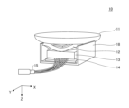
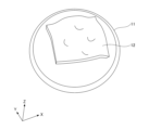
- FIG. 2 is a perspective view showing an example of an input device.
- the input device 10 includes an operation section 11 , a first elastic section 12 , a sensor housing 13 , an installation surface fixing section 14 and a housing 18 .
- the operation part 11 is formed of a concave member, and is pressed mainly in the Z-axis positive direction by the operator's body (hands, fingers, etc.). Note that when the input device 10 is installed on a table or the like, the positive direction of the Z-axis is a direction close to the vertical downward direction in the installed state.
- the first elastic part 12 is an elastic member for suppressing the operation part 11 from separating from the sensor when force is applied to the operation part 11 .
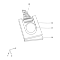
- the sensor housing 13 is a housing that houses the three-dimensional pressure sensor.
- the installation surface fixing portion 14 is a member for fixing the installation surface in the installation state when the input device 10 is installed on a table or the like.
- the installation surface fixing portion 14 is formed, for example, from an earthquake-resistant gel or the like that absorbs shaking.
- the communication line 15 is connected to a three-dimensional pressure sensor housed in the sensor housing 13.
- the housing 18 is a housing that accommodates each part of the input device 10 .
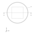
- FIG. 3 is a top view showing an example of an input device.
- the operation unit 11 has a circular shape when viewed from above in the negative direction of the Z axis. Further, the coordinate system in the following description has the sensor plane as the XY plane and the center of the circle of the operation unit 11 on the XY plane as the origin.
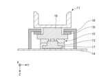
- FIG. 4 is a cross-sectional view showing an example of an input device. 4 is a cross-sectional view along AA in FIG. 3.
- FIG. The operating portion 11 has a convex portion 16 for pressing the sensor 17 .
- the convex portion 16 contacts the sensor 17 and presses it in the Z-axis positive direction. Note that the convex portion 16 may be in direct contact with the sensor 17, or may be configured to press the sensor 17 via the first elastic portion 12, and may not be in direct contact with the sensor 17. .
- the sensor 17 is a three-dimensional pressure sensor housed in the sensor housing 13 and measures the pressure from the four projections 16 .
- the second elastic part 19 is an elastic member located between the housing 18 and the convex part 16 .
- the second elastic portion 19 weakens the pressure of the convex portion 16 and the operation portion 11 pressing against the first elastic portion 12, thereby preventing deterioration of the first elastic portion 12 due to long-term use.
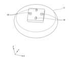
- FIG. 5 is a perspective view showing the structure of the bottom surface of the input device.
- the operation unit 11 has four protrusions 16 at four locations slightly apart from the center of the circle formed by the operation unit 11 in the vertical and horizontal directions.
- the four projections 16 appropriately apply force in eight directions (up, down, left, right, and four oblique directions) at the input of the sensor 17, which is a small three-dimensional pressure sensor.
- the sensor 17 measures pressure values (Px, Py, Pz) in the X, Y and Z directions.
- the operation unit 11 includes a plurality of projections 16 and receives operations by the operator's body. Then, the sensor 17 measures three-dimensional pressure values pressed by the plurality of protrusions.
- FIG. 6 is a perspective view showing an example of an elastic portion included in the input device.
- the first elastic portion 12 is formed so as to cover the convex portion 16 .
- the tilt of the operating portion 11 is absorbed by the first elastic portion 12, so that the projections 16 can be kept in a state of being able to press the sensor 17. be done.
- FIG. 7 is a perspective view showing an example of a sensor included in the input device.
- the sensor 17 is housed in the sensor housing 13 and connected to the communication line 15 .
- the installation surface of the sensor housing 13 is fixed to an installation target such as a table by the installation surface fixing portion 14 in the installation state.
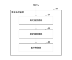
- FIG. 8 is a diagram showing a functional configuration example of an information processing device.
- the information processing device 20 includes a measured value receiving section 21 , a measured value processing section 22 and a display control section 23 .
- the measured value receiving unit 21 receives data (hereinafter also referred to as measured data) indicating measured values (Px, Py, Pz) from the input device 10 .
- the measured value processing unit 22 executes screen operation processing such as cursor movement and selection menu change.
- the display control unit 23 controls the display and the like so that the results of processing by the measurement value processing unit 22 are reflected.
- the information processing device 20 starts measurement value processing by receiving data indicating measurement values from the input device 10 periodically, for example, every second.
- Example 1 is an example of executing a cursor operation based on a measured value.
- a second embodiment is an example of executing a cursor operation, a drag operation, or a range selection operation based on the measured value.
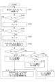
- FIG. 9 is a flowchart illustrating an example of the flow of measurement value processing according to the first embodiment.
- the measurement value processing unit 22 acquires measurement data (Px, Py, Pz) (step S101).
- the measured value processing unit 22 determines whether or not the measured value Px is greater than the threshold Thx (step S102).
- the measured value processing unit 22 determines that the measured value Px is not greater than the threshold value Thx (step S102: NO), it substitutes 0 for the variable Px indicating the measured value (step S103).
- step S102 determines that the measured value Px is greater than the threshold value Thx (step S102: YES). It skips the process of step S103.
- the measured value processing unit 22 determines whether or not the measured value Py is greater than the threshold Thy (step S104).
- step S104 When the measured value processing unit 22 determines that the measured value Py is not greater than the threshold Thy (step S104: NO), it substitutes 0 for the variable Py indicating the measured value (step S105).
- step S104 determines that the measured value Py is greater than the threshold Thy (step S104: YES). It skips the process of step S105.
- the measurement value processing unit 22 determines the cursor direction based on the vector (Px, Py) (step S106). Specifically, the measurement value processing unit 22 determines the direction of the cursor in the direction of the vector (Px, Py), that is, in the direction of the line segment from the origin O to the point (Px, Py).
- the measured value processing unit 22 determines whether or not the measured value Pz is greater than the threshold Thz1 (step S107). Then, when the measured value processing unit 22 determines that the measured value Pz is greater than the threshold Thz1 (step S107: YES), it determines the cursor speed to be V1 (step S108).
- the measured value processing unit 22 determines whether the measured value Pz is greater than the threshold Thz1 (step S107: NO), it determines whether the measured value Pz is greater than the threshold Thz2 (step S109).
- step S109 When the measured value processing unit 22 determines that the measured value Pz is greater than the threshold Thz2 (step S109: YES), it sets the cursor speed to V2 (step S108).
- the measured value processing unit 22 determines that the measured value Pz is not greater than the threshold Thz2 (step S109: NO), it determines the cursor speed to be V3 (step S111).
- step S110 or step S111 the measurement value processing unit 22 controls the display of the cursor based on the determined cursor direction and cursor speed (step S112).
- thresholds Thx, Thy, Thz1, Thz2 and the velocities V1, V2, V3, etc. are predetermined reference values according to the operability of the cursor, the muscle strength of the operator, the degree of physical disability, and the like.
- the measured value processing unit 22 determines the cursor direction according to the measured values Px and Py, and determines the cursor speed according to the measured value Pz.
- FIG. 10 is a flowchart illustrating an example of the flow of measurement value processing according to the second embodiment.
- the measurement value processing unit 22 acquires measurement data (Px, Py, Pz) (step S201).
- the measured value processing unit 22 determines whether or not the measured value Pz is smaller than the threshold Thz (step S202).
- step S202 determines whether the measured value Px is larger than the threshold Thx (step S203).
- the measured value processing unit 22 determines that the measured value Px is not greater than the threshold Thx (step S203: NO), it substitutes 0 for the variable Px indicating the measured value (step S204).
- step S203 determines that the measured value Px is greater than the threshold value Thx (step S203: YES). Also, when the measured value processing unit 22 determines that the measured value Px is greater than the threshold value Thx (step S203: YES), it skips the process of step S204.
- the measured value processing unit 22 determines whether or not the measured value Py is greater than the threshold Thy (step S205).
- step S205 NO
- step S206 When the measured value processing unit 22 determines that the measured value Py is not greater than the threshold Thy (step S205: NO), it substitutes 0 for the variable Py indicating the measured value (step S206).
- step S205 determines that the measured value Py is greater than the threshold Thy (step S205: YES). It skips the process of step S206.
- the measured value processing unit 22 determines the direction and speed of the cursor operation based on the vector (Px, Py), and controls the display (step S207). Specifically, the measurement value processing unit 22 sets the direction of the vector (Px, Py) as the direction of the cursor, and determines the speed of the cursor based on the magnitude of the vector (Px, Py).
- the measurement value processing unit 22 may calculate the cursor speed by multiplying the magnitude of the vector (Px, Py) by a predetermined coefficient, or the result of comparison with a predetermined threshold value may be Accordingly, the cursor speed may be determined step by step.
- the measured value processing unit 22 determines that the measured value Pz is not smaller than the threshold Thz (step S202: NO), it starts the drag operation or range selection operation.
- the measurement value processing unit 22 determines the operation to be started depending on whether or not the cursor to be operated is in contact with an icon or the like on the screen. For example, the measurement value processing unit 22 starts a drag operation when the cursor is in contact with an icon or the like, and starts a range selection operation when the cursor is not in contact with an icon or the like.
- the measurement value processing unit 22 further acquires measurement data (Px, Py, Pz) (step S209).
- the measured value processing unit 22 determines whether or not the measured value Pz is smaller than the threshold Thz (step S210).
- step S210 When the measurement value processing unit 22 determines that the measurement value Pz is smaller than the threshold Thz (step S210: YES), it ends the drag operation or range selection operation (step S211).
- the measured value processing unit 22 determines whether the measured value Pz is not smaller than the threshold Thz (step S210: NO), it determines whether the measured value Px is larger than the threshold Thx (step S212).
- the measured value processing unit 22 determines that the measured value Px is not greater than the threshold Thx (step S212: NO), it substitutes 0 for the variable Px indicating the measured value (step S213).
- step S212 determines that the measured value Px is greater than the threshold value Thx (step S212: YES). It skips the process of step S213.
- the measured value processing unit 22 determines whether or not the measured value Py is greater than the threshold Thy (step S214).
- the measured value processing unit 22 determines that the measured value Py is not greater than the threshold Thy (step S214: NO), it substitutes 0 for the variable Py indicating the measured value (step S215).
- step S214 determines that the measured value Py is greater than the threshold Thy (step S214: YES). It skips the process of step S215.
- the measured value processing unit 22 determines the direction and speed of the drag operation or range selection operation based on the vector (Px, Py), and controls the display (step S216). Specifically, the measurement value processing unit 22 sets the direction of the vector (Px, Py) as the direction of the drag operation or range selection operation, and determines the direction of the drag operation or range selection operation based on the magnitude of the vector (Px, Py). Determine speed. Then, the measured value processing unit 22 returns to the process of step S208.
- the measured value processing unit 22 determines cursor operation, drag operation, or range selection operation according to the measured value Pz, and determines the direction and direction of the operation according to the measured values Px and Py. Determine speed.
- the flow of the measurement value processing according to each embodiment described above is just an example and may be different.
- the measurement value processing according to the second embodiment when the measurement value Px exceeds the threshold Thx and the measurement value Py exceeds the threshold Thy, the state of the cursor operation or the drag operation is fixed. You can do so.
- the information processing apparatus 20 can be realized, for example, by causing a computer to execute a program describing the processing details described in the present embodiment.
- this "computer” may be a physical machine or a virtual machine on the cloud.
- the "hardware” described here is virtual hardware.
- the above program can be recorded on a computer-readable recording medium (portable memory, etc.), saved, or distributed. It is also possible to provide the above program through a network such as the Internet or e-mail.
- FIG. 11 is a diagram showing a hardware configuration example of the computer.
- the computer of FIG. 11 has a drive device 1000, an auxiliary storage device 1002, a memory device 1003, a CPU 1004, an interface device 1005, a display device 1006, an input device 1007, an output device 1008, etc., which are interconnected by a bus B, respectively.
- a program that implements the processing in the computer is provided by a recording medium 1001 such as a CD-ROM or memory card, for example.
- a recording medium 1001 such as a CD-ROM or memory card
- the program is installed from the recording medium 1001 to the auxiliary storage device 1002 via the drive device 1000 .
- the program does not necessarily need to be installed from the recording medium 1001, and may be downloaded from another computer via the network.
- the auxiliary storage device 1002 stores installed programs, as well as necessary files and data.
- the memory device 1003 reads and stores the program from the auxiliary storage device 1002 when a program activation instruction is received.
- the CPU 1004 implements functions related to the device according to programs stored in the memory device 1003 .
- the interface device 1005 is used as an interface for connecting to the network.
- a display device 1006 displays a program-based GUI (Graphical User Interface) or the like.
- An input device 1007 is composed of a keyboard, a mouse, buttons, a touch panel, or the like, and is used to input various operational instructions.
- the output device 1008 outputs the calculation result.
- the computer may include a GPU (Graphics Processing Unit) or TPU (Tensor Processing Unit) instead of the CPU 1004, or may include a GPU or TPU in addition to the CPU 1004. In that case, the processing may be divided and executed, for example, the GPU or TPU executes processing that requires special computation, and the CPU 1004 executes other processing.
- the input device having the concave operation portion transmits to the information processing device data indicating the measured value by the three-dimensional pressure sensor installed at the bottom of the operation portion.
- the information processing device performs display control to move the cursor displayed on the screen based on the measured value indicated by the received data. Thereby, the operability of the input device can be improved.
- the measurement value processing unit 22 may determine the cursor direction according to the measurement values Px and Pz, and determine the cursor speed according to the measurement value Pz. As a result, the direction and strength of the cursor operation can be adjusted with a small movement such as a paralyzed upper limb.
- the measured value processing unit 22 may determine cursor operation, drag operation, or range selection operation according to the measured value Pz, and may determine the direction and speed of the operation according to the measured values Px and Pz. This makes it unnecessary to select an icon using a touch pad for a drag operation such as the conventional track point, and enables both cursor operation and drag operation by operating only the input device 10 .
- the input device 10 includes a second elastic portion 19 for weakening the force with which the operation portion 11 presses the first elastic portion 12 . As a result, deterioration in strength of the first elastic portion 12 that prevents the operation portion 11 from separating from the sensor 17 can be prevented.
- (Summary of embodiment) At least the input devices, input systems, and input methods described in the following sections are described herein.
- (Section 1) an operation unit having a plurality of projections and receiving an operation by an operator's body; a sensor that measures a three-dimensional pressure value pressed by the plurality of protrusions; a first elastic portion for restraining the operation portion from separating from the sensor; a second elastic portion for weakening the force with which the operation portion presses the first elastic portion; input device.
- (Section 2) Further equipped with a housing, wherein the second elastic portion is an elastic member positioned between the housing and the plurality of convex portions; The input device according to item 1.
- An input system comprising an input device and an information processing device,
- the input device is an operation unit having a plurality of projections and receiving an operation by an operator's body; a first elastic portion for absorbing inclination of the operating portion; a second elastic portion for weakening the force with which the operation portion presses the first elastic portion; a sensor that measures a three-dimensional pressure value pressed by the plurality of convex portions,
- the information processing device is a measurement value receiving unit that receives data indicating a measurement value from the input device; a measurement value processing unit that executes screen operation processing based on the measurement value, input system.
- the measurements include pressure values in the X, Y and Z directions;
- the measurement value processing unit determines a cursor direction according to the pressure value in the X direction and the pressure value in the Y direction, and determines a cursor speed according to the pressure value in the Z direction.
- the input system according to item 4. the measurements include pressure values in the X, Y and Z directions;
- the measurement value processing unit determines a cursor operation, a drag operation, or a range selection operation according to the pressure value in the Z direction, and determines the direction of operation according to the pressure value in the X direction and the pressure value in the Y direction. and determine the speed,
- the input device is an operation unit having a plurality of projections and receiving an operation by an operator's body; a sensor that measures a three-dimensional pressure value pressed by the plurality of protrusions; a first elastic portion for restraining the operation portion from separating from the sensor; a second elastic portion for weakening the force with which the operation portion presses the first elastic portion; a step in which the information processing device receives data indicating a measurement value from the input device; the information processing device executing a screen operation process based on the measured value; input method.
- Input system 10 Input device 11 Operation part 12 First elastic part 13 Sensor housing 14 Installation surface fixing part 15 Communication line 16 Convex part 17 Sensor 18 Housing 19 Second elastic part 20
- Information processing device 21 Measured value receiving part 22 measured value processing unit 23 display control unit 1000 drive device 1001 recording medium 1002 auxiliary storage device 1003 memory device 1004 CPU 1005 interface device 1006 display device 1007 input device 1008 output device
Landscapes
- Engineering & Computer Science (AREA)
- General Engineering & Computer Science (AREA)
- Theoretical Computer Science (AREA)
- Human Computer Interaction (AREA)
- Physics & Mathematics (AREA)
- General Physics & Mathematics (AREA)
- Position Input By Displaying (AREA)
Priority Applications (3)
| Application Number | Priority Date | Filing Date | Title |
|---|---|---|---|
| PCT/JP2021/036827 WO2023058115A1 (ja) | 2021-10-05 | 2021-10-05 | 入力装置、入力システムおよび入力方法 |
| JP2023552439A JPWO2023058115A1 (cg-RX-API-DMAC7.html) | 2021-10-05 | 2021-10-05 | |
| US18/691,250 US20240402840A1 (en) | 2021-10-05 | 2021-10-05 | Input apparatus, input system and input method |
Applications Claiming Priority (1)
| Application Number | Priority Date | Filing Date | Title |
|---|---|---|---|
| PCT/JP2021/036827 WO2023058115A1 (ja) | 2021-10-05 | 2021-10-05 | 入力装置、入力システムおよび入力方法 |
Publications (1)
| Publication Number | Publication Date |
|---|---|
| WO2023058115A1 true WO2023058115A1 (ja) | 2023-04-13 |
Family
ID=85804022
Family Applications (1)
| Application Number | Title | Priority Date | Filing Date |
|---|---|---|---|
| PCT/JP2021/036827 Ceased WO2023058115A1 (ja) | 2021-10-05 | 2021-10-05 | 入力装置、入力システムおよび入力方法 |
Country Status (3)
| Country | Link |
|---|---|
| US (1) | US20240402840A1 (cg-RX-API-DMAC7.html) |
| JP (1) | JPWO2023058115A1 (cg-RX-API-DMAC7.html) |
| WO (1) | WO2023058115A1 (cg-RX-API-DMAC7.html) |
Citations (4)
| Publication number | Priority date | Publication date | Assignee | Title |
|---|---|---|---|---|
| JPH06347350A (ja) * | 1993-06-11 | 1994-12-22 | Nitta Ind Corp | 力・モーメントセンサー |
| JP2001189791A (ja) * | 1999-12-28 | 2001-07-10 | Mitsubishi Electric Corp | 携帯情報端末 |
| JP2002108555A (ja) * | 2000-10-02 | 2002-04-12 | Ngk Insulators Ltd | 座標情報入力装置 |
| JP2010020502A (ja) * | 2008-07-10 | 2010-01-28 | Alps Electric Co Ltd | ポインティングデバイス |
Family Cites Families (14)
| Publication number | Priority date | Publication date | Assignee | Title |
|---|---|---|---|---|
| EP0422589A1 (de) * | 1989-10-12 | 1991-04-17 | Maurer Instruments Ltd | Positionier- und Zielverfolgungsvorrichtung |
| JPH0741634U (ja) * | 1993-12-15 | 1995-07-21 | 靖 島田 | 入力装置 |
| US5714980A (en) * | 1995-10-31 | 1998-02-03 | Mitsumi Electric Co., Ltd. | Pointing device |
| EP0810544B1 (en) * | 1996-05-29 | 2003-04-16 | Fujitsu Takamisawa Component Limited | Pointing device for moving and positioning a pointer on a display of a computer |
| JP4722252B2 (ja) * | 1999-09-22 | 2011-07-13 | 富士通コンポーネント株式会社 | 座標入力装置 |
| TW541192B (en) * | 2000-01-14 | 2003-07-11 | Sony Computer Entertainment Inc | Recording medium recorded with a program that performs processing depending on a plurality of outputs from pressure-sensitive means, computer that executes the processing and method of using same |
| US7092174B2 (en) * | 2001-05-18 | 2006-08-15 | Konica Corporation | Image pickup lens, image pickup apparatus and method for forming image pickup lens |
| JP2003044216A (ja) * | 2001-07-26 | 2003-02-14 | Mitsumi Electric Co Ltd | 座標入力装置及び携帯電話機 |
| JP3983638B2 (ja) * | 2002-09-24 | 2007-09-26 | ニッタ株式会社 | センサシート |
| TWI231689B (en) * | 2004-02-27 | 2005-04-21 | Htc Corp | Handheld electronic device |
| JP5115479B2 (ja) * | 2006-10-12 | 2013-01-09 | 日本電気株式会社 | 操作キー構造 |
| JP5977627B2 (ja) * | 2012-09-07 | 2016-08-24 | シャープ株式会社 | 情報処理装置、情報処理方法およびプログラム |
| US10124249B2 (en) * | 2015-05-01 | 2018-11-13 | Microsoft Technology Licensing, Llc | Game controller with removable controller accessory |
| KR102508193B1 (ko) * | 2016-10-31 | 2023-03-10 | 삼성전자주식회사 | 입력장치 및 이를 갖는 디스플레이 장치 |
-
2021
- 2021-10-05 US US18/691,250 patent/US20240402840A1/en not_active Abandoned
- 2021-10-05 WO PCT/JP2021/036827 patent/WO2023058115A1/ja not_active Ceased
- 2021-10-05 JP JP2023552439A patent/JPWO2023058115A1/ja active Pending
Patent Citations (4)
| Publication number | Priority date | Publication date | Assignee | Title |
|---|---|---|---|---|
| JPH06347350A (ja) * | 1993-06-11 | 1994-12-22 | Nitta Ind Corp | 力・モーメントセンサー |
| JP2001189791A (ja) * | 1999-12-28 | 2001-07-10 | Mitsubishi Electric Corp | 携帯情報端末 |
| JP2002108555A (ja) * | 2000-10-02 | 2002-04-12 | Ngk Insulators Ltd | 座標情報入力装置 |
| JP2010020502A (ja) * | 2008-07-10 | 2010-01-28 | Alps Electric Co Ltd | ポインティングデバイス |
Also Published As
| Publication number | Publication date |
|---|---|
| US20240402840A1 (en) | 2024-12-05 |
| JPWO2023058115A1 (cg-RX-API-DMAC7.html) | 2023-04-13 |
Similar Documents
| Publication | Publication Date | Title |
|---|---|---|
| US10599233B1 (en) | Computer mouse device with modified design and functionality | |
| US20200081534A1 (en) | Devices for Controlling Computers Based on Motions and Positions of Hands | |
| JP3753744B2 (ja) | アイソトニック及びアイソメトリックの機能を有する力フィードバックインタフェース | |
| EP1779221B1 (en) | Method and apparatus for communicating graphical information to a visually impaired person using haptic feedback | |
| EP2365419A2 (en) | Wearable data input device | |
| JP2008203911A (ja) | ポインティング・デバイス、およびコンピュータ | |
| Sathiyanarayanan et al. | Map navigation using hand gesture recognition: A case study using myo connector on apple maps | |
| US20250238083A1 (en) | Device for intuitive dexterous touch and feel interaction in virtual worlds | |
| JPWO2015108112A1 (ja) | 操作判定装置、操作判定方法、および、プログラム | |
| CN109960404B (zh) | 一种数据处理方法及装置 | |
| US20010033268A1 (en) | Handheld ergonomic mouse | |
| Oh et al. | Anywheretouch: Finger tracking method on arbitrary surface using nailed-mounted imu for mobile hmd | |
| Mulfari et al. | Human-computer interface based on IoT embedded systems for users with disabilities | |
| JPH0850531A (ja) | 接触式制御用入力機器 | |
| Xirgo | Accelerometer-based computer mouse for people with special needs | |
| JP7559969B2 (ja) | 入力装置、入力システムおよび入力方法 | |
| WO2023281705A1 (ja) | 入力装置、入力システムおよび入力方法 | |
| Kim et al. | BudsID: Mobile-Ready and Expressive Finger Identification Input for Earbuds | |
| US20240402840A1 (en) | Input apparatus, input system and input method | |
| KR101688193B1 (ko) | 인간-컴퓨터 간 실감 및 제스처 상호작용을 위한 데이터 입력장치 및 그 방법 | |
| KR20240138827A (ko) | 웨어러블 컨트롤러 | |
| Feiz et al. | Exploring feasibility of wrist gestures for non-visual interactions with wearables | |
| JP2020077069A (ja) | フィードバック生成装置 | |
| EP4127881A1 (en) | Computer mouse | |
| WO2023281706A1 (ja) | 入力システム、入力方法およびプログラム |
Legal Events
| Date | Code | Title | Description |
|---|---|---|---|
| 121 | Ep: the epo has been informed by wipo that ep was designated in this application |
Ref document number: 21959857 Country of ref document: EP Kind code of ref document: A1 |
|
| WWE | Wipo information: entry into national phase |
Ref document number: 2023552439 Country of ref document: JP |
|
| NENP | Non-entry into the national phase |
Ref country code: DE |
|
| 122 | Ep: pct application non-entry in european phase |
Ref document number: 21959857 Country of ref document: EP Kind code of ref document: A1 |