WO2023053944A1 - 画像形成装置、接着剤カートリッジ、接着剤容器及びプロセスカートリッジセット - Google Patents
画像形成装置、接着剤カートリッジ、接着剤容器及びプロセスカートリッジセット Download PDFInfo
- Publication number
- WO2023053944A1 WO2023053944A1 PCT/JP2022/034218 JP2022034218W WO2023053944A1 WO 2023053944 A1 WO2023053944 A1 WO 2023053944A1 JP 2022034218 W JP2022034218 W JP 2022034218W WO 2023053944 A1 WO2023053944 A1 WO 2023053944A1
- Authority
- WO
- WIPO (PCT)
- Prior art keywords
- adhesive
- powder
- image forming
- wax
- powder adhesive
- Prior art date
- Legal status (The legal status is an assumption and is not a legal conclusion. Google has not performed a legal analysis and makes no representation as to the accuracy of the status listed.)
- Ceased
Links
Images


Classifications
-
- G—PHYSICS
- G03—PHOTOGRAPHY; CINEMATOGRAPHY; ANALOGOUS TECHNIQUES USING WAVES OTHER THAN OPTICAL WAVES; ELECTROGRAPHY; HOLOGRAPHY
- G03G—ELECTROGRAPHY; ELECTROPHOTOGRAPHY; MAGNETOGRAPHY
- G03G9/00—Developers
- G03G9/08—Developers with toner particles
- G03G9/097—Plasticisers; Charge controlling agents
- G03G9/09733—Organic compounds
-
- G—PHYSICS
- G03—PHOTOGRAPHY; CINEMATOGRAPHY; ANALOGOUS TECHNIQUES USING WAVES OTHER THAN OPTICAL WAVES; ELECTROGRAPHY; HOLOGRAPHY
- G03G—ELECTROGRAPHY; ELECTROPHOTOGRAPHY; MAGNETOGRAPHY
- G03G21/00—Arrangements not provided for by groups G03G13/00 - G03G19/00, e.g. cleaning, elimination of residual charge
-
- G—PHYSICS
- G03—PHOTOGRAPHY; CINEMATOGRAPHY; ANALOGOUS TECHNIQUES USING WAVES OTHER THAN OPTICAL WAVES; ELECTROGRAPHY; HOLOGRAPHY
- G03G—ELECTROGRAPHY; ELECTROPHOTOGRAPHY; MAGNETOGRAPHY
- G03G9/00—Developers
- G03G9/08—Developers with toner particles
-
- G—PHYSICS
- G03—PHOTOGRAPHY; CINEMATOGRAPHY; ANALOGOUS TECHNIQUES USING WAVES OTHER THAN OPTICAL WAVES; ELECTROGRAPHY; HOLOGRAPHY
- G03G—ELECTROGRAPHY; ELECTROPHOTOGRAPHY; MAGNETOGRAPHY
- G03G9/00—Developers
- G03G9/08—Developers with toner particles
- G03G9/0819—Developers with toner particles characterised by the dimensions of the particles
-
- G—PHYSICS
- G03—PHOTOGRAPHY; CINEMATOGRAPHY; ANALOGOUS TECHNIQUES USING WAVES OTHER THAN OPTICAL WAVES; ELECTROGRAPHY; HOLOGRAPHY
- G03G—ELECTROGRAPHY; ELECTROPHOTOGRAPHY; MAGNETOGRAPHY
- G03G9/00—Developers
- G03G9/08—Developers with toner particles
- G03G9/087—Binders for toner particles
-
- G—PHYSICS
- G03—PHOTOGRAPHY; CINEMATOGRAPHY; ANALOGOUS TECHNIQUES USING WAVES OTHER THAN OPTICAL WAVES; ELECTROGRAPHY; HOLOGRAPHY
- G03G—ELECTROGRAPHY; ELECTROPHOTOGRAPHY; MAGNETOGRAPHY
- G03G9/00—Developers
- G03G9/08—Developers with toner particles
- G03G9/097—Plasticisers; Charge controlling agents
-
- G—PHYSICS
- G03—PHOTOGRAPHY; CINEMATOGRAPHY; ANALOGOUS TECHNIQUES USING WAVES OTHER THAN OPTICAL WAVES; ELECTROGRAPHY; HOLOGRAPHY
- G03G—ELECTROGRAPHY; ELECTROPHOTOGRAPHY; MAGNETOGRAPHY
- G03G2215/00—Apparatus for electrophotographic processes
- G03G2215/06—Developing structures, details
- G03G2215/0602—Developer
- G03G2215/0604—Developer solid type
- G03G2215/0624—Developer solid type plural systems represented (e.g. in a multicolour device or for optimising photo line development)
-
- G—PHYSICS
- G03—PHOTOGRAPHY; CINEMATOGRAPHY; ANALOGOUS TECHNIQUES USING WAVES OTHER THAN OPTICAL WAVES; ELECTROGRAPHY; HOLOGRAPHY
- G03G—ELECTROGRAPHY; ELECTROPHOTOGRAPHY; MAGNETOGRAPHY
- G03G2221/00—Processes not provided for by group G03G2215/00, e.g. cleaning or residual charge elimination
- G03G2221/16—Mechanical means for facilitating the maintenance of the apparatus, e.g. modular arrangements and complete machine concepts
- G03G2221/18—Cartridge systems
- G03G2221/183—Process cartridge
Definitions
- the present disclosure relates to an image forming apparatus that develops an electrostatic latent image on a transfer material using an electrophotographic method to form a toner image and an adhesive portion made of a powder adhesive that functions as an adhesive, as well as the image forming apparatus.
- the present invention relates to an adhesive cartridge, an adhesive container and a process cartridge set used in an image forming apparatus.
- pre-printed paper is prepared in advance and variable data is printed on each pre-printed paper.
- a sealing process was performed as a treatment. In this method, it takes a long time to prepare preprinted paper, which requires the printing of format such as ruled lines and the application of adhesive.
- Patent Documents 1 and 2 describe that an electrophotographic process is performed using a printing toner and a resin powder having an adhesive function (hereinafter referred to as a powder adhesive) in a sheet-like bag material. ing. Accordingly, there has been proposed a bag making apparatus that outputs a bag-shaped product while omitting the step of preparing preprinted paper. In these bag-making apparatuses, printing toner and powder adhesive are transferred to a sheet, and after that, the sheet is thermally fixed, the sheet is folded, and the sheet is heated and pressed to form a bag. create deliverables. Further, in Patent Document 3, in the powder image formed on the recording medium, the amount of the powder adhesive per unit area is made larger than that of the printing toner, thereby improving the adhesive force.
- a powder adhesive an adhesive function
- the present disclosure provides an image forming apparatus capable of suppressing the occurrence of fogging while improving adhesive strength even if the amount of application per unit area on a sheet is increased, an adhesive cartridge, an adhesive container, and a process cartridge set used in the image forming apparatus. I will provide a.
- the present disclosure includes a printing image forming unit for forming a printing toner image with printing toner;
- An image forming apparatus comprising: an adhesive image forming unit for forming an image of the powder adhesive with the powder adhesive,
- the printing toner contains a wax
- the powder adhesive contains wax
- the present invention relates to an image forming apparatus, wherein the wax content in the powder adhesive is higher than the wax content in the printing toner.
- an image forming apparatus capable of improving the adhesive strength even if the amount of application per unit area on the sheet is increased, and also capable of suppressing fogging.
- FIG. 4 is a diagram for explaining attachment of the post-processing unit to the main body of the image forming apparatus; Schematic diagram for explaining the state of a toner image transferred onto a sheet 2A and 2B are diagrams showing a sheet conveying path in an image forming apparatus; Figures (a to f) for explaining the contents of the folding process according to the first embodiment.
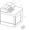
- 1 is a perspective view showing the appearance of an image forming apparatus according to Embodiment 1;
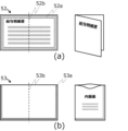
- FIG. FIGS. 4A and 4B exemplify products output by the image forming apparatus according to the first embodiment;
- FIGS. Schematic diagram of process cartridge according to embodiment 1 FIG.
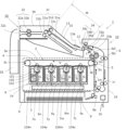
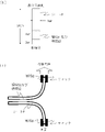
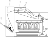
- FIG. 1 is a schematic diagram showing a cross-sectional configuration of an image forming apparatus 1 including an image forming apparatus main body (hereinafter referred to as apparatus main body 10) and a post-processing unit 30 connected to the apparatus main body 10.
- the image forming apparatus 1 is an electrophotographic image forming apparatus (electrophotographic system) including an apparatus main body 10 having an electrophotographic printing mechanism and a post-processing unit 30 as a sheet processing apparatus.
- the image forming apparatus 1 includes a print image forming unit (process cartridges 7y, 7m, and 7c) as a first image forming unit for forming a print toner image using a print toner, and a powder adhesive.
- image forming means image forming unit 1e having an adhesive image forming section (process cartridge 7n) as a second image forming section for forming an image of the powder adhesive by using a toner image for printing and the powder adhesive and a fixing means 6 for fixing the toner image for printing and the image of the powder adhesive transferred to the transfer material onto the transfer material.
- the print image forming units are detachable from the apparatus main body. At least part of the process cartridges (7y, 7m, 7c) constituting the print image forming section (for example, photosensitive drums and/or developing rollers) may be fixed to the main body of the apparatus. Also, the adhesive image forming section (process cartridge 7n) is detachable from the apparatus main body. Similarly, at least part of the process cartridge (7n) constituting the adhesive image forming section (for example, the photosensitive drum and/or developing roller) may be fixed to the apparatus main body.
- the print image forming unit includes a first image carrier (first photoreceptor) and a first developer carrier for developing an electrostatic latent image formed on the first image carrier with a printing toner. and a body.
- the adhesive image forming unit includes a second image carrier (second photoreceptor) and a second developer carrier for developing an electrostatic latent image formed on the second image carrier with a powder adhesive. , may have
- FIG. 2 is a cross-sectional view showing a positioning portion when attaching the post-processing unit 30 to the apparatus main body 10.
- the post-processing unit 30 can be detachably attached to the apparatus main body 10 . By aligning the connector 36 on the post-processing unit 30 with the connector 37 on the apparatus main body 10, it can be attached.
- FIG. 6 is a perspective view showing the appearance of the image forming apparatus 1.
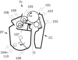
- FIG. 8 is a schematic diagram of a process cartridge.
- the post-processing unit 30 is mounted on the upper portion of the apparatus main body 10.
- the image forming apparatus 1 has a sheet cassette 8 on the bottom, an openable and closable tray 20 on the right side, and a first discharge tray 13 on the top.
- the apparatus main body 10 includes a sheet cassette 8 as a sheet storage portion for storing sheets P as a transfer material (recording medium), an image forming unit 1e as image forming means, and a fixing means.
- a first fixing device 6 and a housing 19 that accommodates them are provided.
- the apparatus main body 10 has a printing function of forming a toner image on the sheet P fed from the sheet cassette 8 by the image forming unit 1 e and fixing the toner image by the first fixing device 6 to create a print.
- the sheet cassette 8 is inserted into the housing 19 in the lower part of the apparatus main body 10 so as to be able to be pulled out, and stores a large number of sheets P.
- the sheets P stored in the sheet cassette 8 are fed from the sheet cassette 8 by a feeding member such as a feeding roller, separated one by one by a separation roller pair, and conveyed by the conveying roller 8a. It is also possible to feed the sheets set on the open tray 20 (FIG. 6) one by one.
- the image forming unit 1e is a tandem electrophotographic unit including four process cartridges 7n, 7y, 7m, 7c, a scanner unit 2, and a transfer unit 3.
- a process cartridge is an integrally replaceable unit of a plurality of parts responsible for an image forming process.
- the apparatus main body 10 is provided with a cartridge support portion 9 supported by a housing 19, and each of the process cartridges 7n, 7y, 7m, and 7c is mounted on the cartridge support portion 9 in mounting portions 9n, 9y, 9m, and 9m. It is detachably attached to 9c.
- the cartridge support portion 9 may be a tray member that can be pulled out from the housing 19 .
- each of the process cartridges 7n, 7y, 7m and 7c has substantially the same configuration except for the types of powder contained in the four powder containing portions 104n, 104y, 104m and 104c. That is, each of the process cartridges 7n, 7y, 7m, and 7c includes a photosensitive drum 101 as an image bearing member, a charging roller 102 as a charger, powder storage units 104n, 104y, 104m, and 104c for storing powder, and powder storage units 104n, 104y, 104m, 104c. It also includes a developing roller 105 that performs development using a body.
- the three powder storage units 104y, 104m, and 104c on the right side in the drawing contain toner (first powder) for forming a visible image on the sheet P, yellow, Magenta and cyan printing toners Ty, Tm, and Tc are accommodated.
- the leftmost powder containing portion 104n in the figure contains powder adhesive Tn, which is powder (second powder) for performing adhesion processing after printing.
- the powder storage units 104y, 104m, and 104c are all examples of first toner cartridges that store printing toners Ty, Tm, and Tc. Also, the powder containing portion 104n is an example of a second toner cartridge containing a powder adhesive.
- the process cartridges 7y, 7m, and 7c are all examples of the first process cartridge that forms a toner image using printing toner, and the process cartridge 7n forms an image of the powder adhesive in a predetermined application pattern. It is an example of a second process cartridge to be formed.
- Each developing roller 105, developer supply roller 106, developing blade 107, charging roller 102 shown in FIG. 8, transfer means (transfer unit) 3 shown in FIG. 1, and secondary transfer roller 5 are voltage applying means (not shown).
- a black image such as text
- it is expressed in process black by superimposing yellow (Ty), magenta (Tm), and cyan (Tc) toners.
- Ty yellow
- Tm magenta
- Tc cyan
- a fifth process cartridge using black printing toner may be added to the image forming unit 1e so that a black image can be expressed with black printing toner.
- the type and number of printing toners can be changed according to the application of the image forming apparatus 1 .
- the scanner unit 2 is arranged below the process cartridges 7n, 7y, 7m, and 7c and above the sheet cassette 8.
- the scanner unit 2 is exposure means for writing an electrostatic latent image by irradiating the photosensitive drum 101 of each of the process cartridges 7n, 7y, 7m, and 7c with laser light G. As shown in FIG.
- the transfer means 3 includes a transfer belt 3a as an intermediate transfer member (secondary image carrier).
- the transfer belt 3a is a belt member wound around the inner secondary transfer roller 3b and the tension roller 3c, and faces the photosensitive drums 101 of the process cartridges 7n, 7y, 7m, and 7c on the outer peripheral surface thereof.
- a primary transfer roller 4 is arranged at a position corresponding to each photosensitive drum 101 on the inner peripheral side of the transfer belt 3a.
- a secondary transfer roller 5 is arranged at a position facing the inner secondary transfer roller 3b.
- a transfer nip 5n between the secondary transfer roller 5 and the transfer belt 3a is a transfer portion (secondary transfer portion) where the toner image is transferred onto the sheet P from the transfer belt 3a.
- the first fixing device 6 is arranged above the secondary transfer roller 5 .
- the first fixing device 6 is a thermal fixing type fixing device having a heating roller 6a as a fixing member and a pressure roller 6b as a pressure member.
- the heating roller 6a is heated by a heating element such as a halogen lamp or a ceramic heater, or by an induction heating mechanism.
- the heating temperature during the printing operation is set to 220°C.
- the pressure roller 6b is pressed against the heating roller 6a by an urging member such as a spring, and exerts pressure to press the sheet P passing through the nip (fixing nip 6n) between the heating roller 6a and the pressure roller 6b.
- the housing 19 is provided with a discharge port 12 (first discharge port) that is an opening for discharging the sheet P from the apparatus main body 10 , and a discharge unit 34 is arranged in the discharge port 12 .
- the discharging unit 34 which is discharging means, uses a so-called triple roller having a first discharging roller 34a, an intermediate roller 34b, and a second discharging roller 34c.
- a switching guide 33 that is a flap-shaped guide for switching the conveying path of the sheet P is provided between the first fixing device 6 and the discharge unit 34 .
- the switching guide 33 is rotatable around the shaft portion 33a so that the tip 33b reciprocates in the direction of the arrow c in the figure.
- the apparatus main body 10 has a mechanism for performing double-sided printing.
- a motor (not shown) is connected to the discharge unit 34 so that the rotation direction of the intermediate roller 34b can be rotated forward and backward.
- a double-sided transport path 1r is provided as a transport path connected in a loop to the main transport path 1m.
- the sheet P on which an image is formed on the first surface while passing through the main transport path 1m is nipped and transported between the first discharge roller 34a and the intermediate roller 34b by the switching guide 33 rotated clockwise.
- the switching guide 33 rotates counterclockwise and the intermediate roller 34b rotates in the opposite direction, so that the sheet P is reversely conveyed to the double-sided conveying path 1r.
- An image is formed on the second surface of the sheet P while the sheet P is reversing its front and back and passing through the main transport path 1m again.
- the sheet P after double-sided printing is nipped and conveyed by the intermediate roller 34 b and the second discharge roller 34 c by the switching guide 33 rotated counterclockwise, and discharged from the apparatus main body 10 .
- a conveying path passing through the conveying roller 8a, the transfer nip 5n, and the fixing nip 6n in the apparatus main body 10 constitutes a main conveying path 1m in which image formation on the sheet P is performed.
- the main conveying path 1m extends horizontally with respect to the image forming unit 1e when viewed from the main scanning direction during image formation (the sheet width direction perpendicular to the conveying direction of the sheet conveyed along the main conveying path 1m). It extends from bottom to top through one side.
- the apparatus main body 10 is a so-called vertical transport type (vertical path type) printer in which the main transport path 1m extends in a substantially vertical direction.
- the first discharge tray 13, the intermediate path 15 and the sheet cassette 8 overlap each other. Therefore, the moving direction of the sheet when the discharge unit 34 discharges the sheet P in the horizontal direction is opposite to the moving direction of the sheet when the sheet P is fed from the sheet cassette 8 in the horizontal direction.
- the horizontal occupied range of the body portion of the post-processing unit 30 excluding the second discharge tray 35 is the occupied range of the apparatus body 10. It is preferable that the image forming apparatus 1 having the adhesive printing function can be installed in an installation space equivalent to that of a normal vertical pass printer. becomes.
- the post-processing unit 30 is attached to the upper part of the apparatus main body 10. As shown in FIG. 1, a folder 31 as folding means and a second fixing device 32 as bonding means (second fixing means) are housed in a housing (second housing) 39 and integrated. post-processing unit.
- the post-processing unit 30 is provided with a first discharge tray 13 that rotatably holds the tray switching guide 13a, an intermediate path 15, and a second discharge tray 35.
- the first discharge tray 13 is provided on the upper surface of the post-processing unit 30 and positioned on the upper surface of the entire image forming apparatus 1 (FIG. 1). The function of each part provided in the post-processing unit 30 will be described later.
- the post-processing unit 30 has a positioning portion (for example, a convex shape that engages with a concave portion of the housing 19) for positioning the housing 39 with respect to the housing 19 (first housing) of the apparatus main body 10. is provided.
- the post-processing unit 30 is provided with a drive source and a control section (not shown) that are separate from those of the apparatus main body 10. By connecting the connector 36 of the post-processing unit 30 and the connector 37 of the apparatus main body 10, It is electrically connected to the device body 10 .
- the post-processing unit 30 uses power supplied through the apparatus main body 10 to operate based on commands from a control section (not shown) provided in the apparatus main body 10 .
- the cartridge set includes first cartridges (7y, 7m, 7c) forming a print image forming section and a second cartridge 7n (adhesive cartridge) forming an adhesive image forming section.
- the print image forming section includes the first cartridge
- the adhesive image forming section includes the second cartridge.
- the first cartridge includes a first developer carrier that carries printing toner.
- the first cartridge may have a first image carrier carrying a print toner image formed by the print toner carried on the first developer carrier.
- a first image carrier is capable of carrying an electrostatic latent image.
- the first cartridge includes toner containers (powder storage units 104y, 104m, and 104c) that store printing toner, a first image carrier (first photoreceptor), and the first image carrier. and a first developer bearing member (first developing roller) for developing an electrostatic latent image formed on the member with the printing toner.
- the first image carrier is the photoreceptor 101 in the first cartridge (7y, 7m, 7c).
- the first developing roller is the developing roller 105 in the first cartridge (7y, 7m, 7c).
- the second cartridge has a second developer carrier that carries a powder adhesive.
- the second cartridge may have a second image carrier carrying an adhesive image formed by powdered adhesive carried on the second developer carrier.
- a second image carrier may carry an electrostatic latent image.
- the second cartridge includes a powder adhesive container (104n) containing a powder adhesive, a second image carrier (second photoreceptor) (101), and a second image carrier. and a second developer carrier (second developer roller) (105) for developing the electrostatic latent image with a powder adhesive.
- the first cartridge and the second cartridge may have a developing blade 107 as a developer regulating member for regulating the layer thickness of the printing toner or powder adhesive.
- FIG. 8 is a schematic sectional view of the process cartridge 7n.
- the process cartridge 7n includes a photosensitive unit CC including a photosensitive drum 101 and the like, and a developing unit DT including a developing roller 105 and the like.
- a photosensitive drum 101 is rotatably attached to the photosensitive unit CC via a bearing (not shown).
- the photosensitive drum 101 can form an electrostatic latent image on its surface by applying an undercoat layer, an insulating layer, a photosensitive layer, and a charge transfer layer to an aluminum cylinder of ⁇ 24 mm.
- the photosensitive drum 101 receives the driving force of a driving motor as driving means (driving source) (not shown), and is driven to rotate clockwise (arrow w) in the figure at 300 mm/sec in accordance with the image forming operation. be.
- a charging roller 102 for charging the photosensitive drum 101 and a cleaning member 103 are arranged around the photosensitive drum 101 in the photosensitive unit CC.
- the developing unit DT is provided with a developing roller 105 as a developer bearing member that contacts the photosensitive drum 101 and rotates in the counterclockwise direction (arrow d) in the figure.
- the developing roller 105 has a conductive rubber of ⁇ 12 mm arranged around a metal core.
- the developing roller 105 and the photosensitive drum 101 rotate so that their surfaces move in the same direction at their facing portions (contact portions).
- the rotation speed of the developing roller 105 was faster than that of the photosensitive drum 101 and was set to 450 mm/sec.
- a developer supply roller 106 (hereinafter simply referred to as “supply roller”) is arranged as a developer supply member rotating at 320 mm/sec in the counterclockwise direction (arrow e) in the figure.
- the supply roller 106 has a conductive sponge with a diameter of 13 mm arranged around a metal core.
- the supply roller 106 and the development roller 105 rotate so that their surfaces move in opposite directions at their facing portions (contact portions).
- the supply roller 106 supplies the powder adhesive (printing toner Ty, Tm, and Tc in the case of the process cartridges 7y, 7m, and 7c) onto the development roller 105, and removes the powder adhesive remaining on the development roller 105 ( In the case of the process cartridges 7 y , 7 m and 7 c , the toner for printing (Ty, Tm and Tc) is removed from the developing roller 105 .
- the layer thickness of the powder adhesive (printing toner Ty, Tm, and Tc in the case of the process cartridges 7y, 7m, and 7c) supplied onto the developing roller 105 by the supply roller 106 is regulated.
- a developing blade 107 is arranged as a developer regulating member. The direction of rotation of the supply roller 106 does not matter as long as the toner on the developing roller 105 can be stripped off and the toner can be supplied onto the developing roller 105 .
- a powder adhesive (printing toner Ty, Tm, Tc in the case of the process cartridges 7y, 7m, 7c) is stored as powder in the powder storage unit 104n.
- a stirring member 108 is rotatably supported in the powder containing portion 104n. The stirring member 108 rotates clockwise (arrow f) in the drawing to stir the powder contained in the powder container 104n. to convey the powder.
- the photoreceptor unit CC and the developing unit DT may be separately provided as a photoreceptor unit cartridge and a developing unit cartridge, respectively, and configured to be detachable from the main body of the image forming apparatus. Further, it is also possible to construct a toner cartridge that has only the powder containing portion 104 and the conveying member 108 and that can be attached to and detached from the apparatus main body.
- a developing unit cartridge set including a first developing unit cartridge and a second developing unit cartridge that are detachable from the image forming apparatus 1 can be used.
- the first developing unit cartridge includes a toner container containing printing toner, a first developing roller for developing an electrostatic latent image formed on the photoreceptor with the printing toner, and printing on the first developing roller. and a developing blade as a developer regulating member for regulating the layer thickness of the toner.
- the second developing unit cartridge includes a powder adhesive container containing a powder adhesive, a second developing roller for developing the electrostatic latent image formed on the photoreceptor with the powder adhesive, and a second developing. and a developing blade as a developer regulating member for regulating the layer thickness of the powder adhesive on the roller.
- it can be a toner cartridge set having a first toner cartridge and a second toner cartridge that are detachable from the image forming apparatus 1 .
- the first toner cartridge is detachably provided in the print image forming section and contains printing toner.
- a second toner cartridge is provided in the adhesive image forming section and contains powdered adhesive.
- the adhesive cartridge as a cartridge 7n containing powdered adhesive.
- the adhesive cartridge is used in an image forming apparatus having a print image forming section for forming a printing toner image with a wax-containing printing toner and an adhesive image forming section for forming a powder adhesive image with a powder adhesive. It is attachable to and detachable from the forming unit.
- the adhesive cartridge forms a powder adhesive image with a powder adhesive as an adhesive imaging station.
- the powder adhesive contains wax, and the content of wax in the adhesive powder is higher than the content of wax in the toner for printing.
- the adhesive cartridge has a second developer carrier for developing an electrostatic latent image formed on a second image carrier (second photoreceptor) with powder adhesive.
- the second image carrier may be provided at a position other than the adhesive cartridge in the image forming apparatus, or may be contained in the adhesive cartridge.
- the adhesive cartridge includes a second image carrier (second photoreceptor) and a second image carrier for developing an electrostatic latent image formed on the second image carrier (second photoreceptor) with a powder adhesive. and a developing blade as a developer regulating member for regulating the layer thickness of the powder adhesive on the second developing roller.
- the present disclosure provides an adhesive container as the powder container 104n.
- the adhesive container comprises a print image forming section for forming a print toner image with a wax-containing printing toner and an adhesive image forming section for forming a powder adhesive image with a powder adhesive. It is detachable from the forming device.
- the adhesive container includes a powder containing portion 104n containing powdered adhesive. The powder adhesive contained in the powder container contains wax, and the wax content in the powder adhesive is greater than the wax content in the printing toner.
- FIG. 3A and 3B are schematic diagrams for explaining the state of the toner image transferred onto the sheet P.
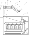
- FIGS. 4A and 4B are diagrams showing a sheet conveying path in the image forming apparatus 1.
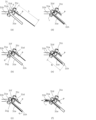
- FIG. 5(a) to 5(f) are diagrams for explaining the contents of the folding process.
- FIGS. 7A and 7B are diagrams exemplifying products output by the image forming apparatus 1.
- FIG. 3A and 3B are schematic diagrams for explaining the state of the toner image transferred onto the sheet P.
- FIGS. 4A and 4B are diagrams showing a sheet conveying path in the image forming apparatus 1.
- FIG. 5(a) to 5(f) are diagrams for explaining the contents of the folding process.
- FIGS. 7A and 7B are diagrams exemplifying products output by the image forming apparatus 1.
- a control section (not shown) of the image forming apparatus 1 conveys the sheet P to form an image, and if necessary Then, a series of operations (image forming operations) for performing post-processing by the post-processing unit 30 are started.
- the image forming operation first, as shown in FIG. 1, the sheets P are fed one by one from the sheet cassette 8 and conveyed toward the transfer nip 5n via the conveying roller 8a.
- the process cartridges 7n, 7y, 7m, and 7c are sequentially driven, and the photosensitive drum 101 is rotated clockwise (arrow w) in the figure. At this time, the surface of the photosensitive drum 101 is uniformly charged by the charging roller 102 .
- the scanner unit 2 irradiates the photosensitive drums 101 of the process cartridges 7n, 7y, 7m, and 7c with a laser beam G modulated based on image data to form electrostatic latent images on the surfaces of the photosensitive drums 101. .
- the electrostatic latent image on the photosensitive drum 101 is developed as a powder image by the powder carried on the developing roller 105 of each of the process cartridges 7n, 7y, 7m and 7c.
- the powder adhesive layer formed on the photosensitive drum 101 by being developed with the powder adhesive Tn is not intended to transmit visual information. are different from the toner images (ordinary toner images) of the printing toners Ty, Tm, and Tc.
- the layer of the powder adhesive Tn developed in a shape corresponding to the application pattern by the electrophotographic process is also a "toner image". treated as one of
- the transfer belt 3a rotates in the counterclockwise direction (arrow v) in the figure.
- a toner image formed in each of the process cartridges 7n, 7y, 7m, and 7c is primarily transferred from the photosensitive drum 101 to the transfer belt 3a by an electric field formed between the photosensitive drum 101 and the primary transfer roller 4.
- FIG. 1 A toner image formed in each of the process cartridges 7n, 7y, 7m, and 7c is primarily transferred from the photosensitive drum 101 to the transfer belt 3a by an electric field formed between the photosensitive drum 101 and the primary transfer roller 4.
- the process cartridge 7n using the powder adhesive Tn is positioned most upstream among the four process cartridges in the rotation direction of the transfer belt 3a.
- Yellow, magenta, and cyan process cartridges 7y, 7m, and 7c are arranged in order from the process cartridge 7n toward the downstream side in the rotation direction of the transfer belt 3a. Therefore, as shown in FIG. 3, when four types of toner images are superimposed on the transfer belt 3a, the powder adhesive Tn becomes the bottom layer (the layer in contact with the transfer belt 3a), and yellow (Ty) and magenta toner images are placed thereon. (Tm) and cyan (Tc) printing toners overlap in order.
- the toner image carried on the transfer belt 3a and reaching the transfer nip 5n is transferred to the sheet P conveyed along the main conveying path 1m by the electric field formed between the secondary transfer roller 5 and the secondary transfer inner roller 3b. is secondarily transcribed to At that time, the toner layer is turned upside down. That is, on the sheet P that has passed through the transfer nip 5n, cyan (Tc), magenta (Tm), and yellow (Ty) printing toners are superimposed from the bottom layer (the layer in contact with the sheet P), and powder is further applied thereon. A layer of adhesive Tn is formed. Therefore, in the toner image transferred to the sheet P, the layer of the powder adhesive Tn is the outermost surface.
- the sheet P is conveyed to the first fixing device 6 and subjected to heat fixing processing. That is, when the sheet P passes through the fixing nip 6n, the toner image on the sheet P is heated and pressurized to melt the printing toners Ty, Tm, and Tc and the powder adhesive Tn, and then fix them. , an image fixed on the sheet P is obtained.
- the sheet P discharged from the apparatus main body 10 regardless of single-sided printing or double-sided printing is sandwiched between the intermediate roller 34b and the second discharge roller 34c, and is placed in the tray. It is conveyed to the first route R1 or the second route R2 by the switching guide 13a.
- the sheet P that has passed through the first fixing device 6 is discharged to the first discharge tray 13 by the discharge unit 34 in the normal printing mode that does not use the post-processing unit 30. is the route.
- the second path R2 shown in FIG. 4B is for the sheet P that has passed through the first fixing device 6 to pass through the discharge unit 34, the folding device 31, and the second fixing device 32 in the adhesive printing mode to the second discharge tray. 35 is the route to be discharged.
- An intermediate path 15 is provided between the first fixing device 6 and the folding device 31 on the second route R2.
- the intermediate path 15 is a sheet conveying path passing through the upper surface (top surface) of the image forming apparatus 1 and extends substantially parallel to the first discharge tray 13 below the first discharge tray 13 .
- the intermediate path 15 and the first discharge tray 13 are inclined upward in the vertical direction toward the folder 31 in the horizontal direction. Therefore, the pair of guide rollers (31c, 31d) below the entrance of the folder 31 is located vertically above the exit of the apparatus main body 10 (the nip between the intermediate roller 34b and the second discharge roller 34c).
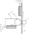
- the folder 31 has four rollers, a first guide roller 31c, a second guide roller 31d, a first folding roller 31a and a second folding roller 31b, and a pull-in portion 31e.
- the first guide roller 31c and the second guide roller 31d are a guide roller pair that nips and conveys the sheet P received from the upstream conveying path of the folder 31 (the intermediate path 15 in this embodiment).
- the first folding roller 31a and the second folding roller 31b are a pair of folding rollers that send out the sheet P while folding it.
- the distance M (FIG. 1) from the second discharge roller 34c to the first guide roller 31c in the sheet conveying direction along the second route R2 is the total length L (FIG. 5) of the sheet P before the folding process in the conveying direction. (a)) is configured to be shorter. In other words, the lower limit of the length in the conveying direction of the sheet that can be processed by the post-processing unit 30 is determined by the distance M between the second discharge roller 34c and the first guide roller 31c. With this configuration, the sheet P is smoothly transferred from the discharge unit 34 to the guide roller pair.
- the folding process by the folding device 31 will be described with reference to FIGS. 5(a) to 5(f).
- the first guide roller 31c and the first folding roller 31a rotate clockwise in the drawing
- the second guide roller 31d and the second folding roller 31b rotate counterclockwise in the drawing.
- the leading edge q of the sheet P delivered from the discharge unit 34 is drawn into the guide roller pair (31c, 31d) as shown in FIG. 5(a).
- the leading edge q of the sheet P is guided downward by the guide wall 31f and comes into contact with the first folding roller 31a. 31d and comes into contact with the wall 31g of the retracted portion 31e.
- the leading edge q advances into the pull-in portion 31e while making sliding contact with the wall 31g.
- the tip q abuts against the end 31h of the lead-in portion 31e as shown in FIG. 5(c).
- the lead-in portion 31e forms a space extending substantially parallel to the intermediate path 15 below the intermediate path 15, and the sheet P is wrapped around the second guide roller 31d at the stage of FIG. It will be bent into a U shape.
- the midsection r begins to bend as shown in FIG. 5(d).
- the middle portion r comes into contact with the second folding roller 31b, and is pulled into the nip portion of the folding roller pair (31a, 31b) by the frictional force received from the second folding roller 31b.
- the sheet P is discharged with the middle portion r at the head by the pair of folding rollers (31a, 31b) while being folded with the middle portion r as the fold line.
- the depth N (FIG. 5(e)) of the pull-in portion 31e that is, the distance from the nip portion of the pair of folding rollers (31a, 31b) to the end portion 31h of the pull-in portion 31e is half the total length L of the sheet P. is set to a length of As a result, the folding device 31 can perform the process of folding the sheet P in half (half-folding). By changing the depth N of the lead-in portion 31e, the position of the fold can be arbitrarily changed.
- the folding device 31 described above is an example of the folding means, and for example, a folding mechanism that presses a blade against the sheet P and pushes it into the nip portion of the pair of rollers to form a fold may be used. Further, the content of the folding process is not limited to double-folding, and a folding mechanism that performs Z-folding or tri-folding, for example, may be used.
- the folding device 31 is composed of a rotating roller and a fixed pull-in portion 31e, so that the driving mechanism can be simplified compared to a folding mechanism that uses a reciprocating blade.
- the folding unit 31 may be provided with a retracting portion 31e having a depth N that is half the length of the sheet.
- the sheet P that has passed through the folding device 31 is conveyed to the second fixing device 32 as shown in FIG. 4(b).
- the second fixing device 32 has a configuration of a thermal fixing system like the first fixing device 6 . That is, the second fixing device 32 has a heating roller 32b as a heating member and a pressure roller 32a as a pressure member.
- the heating roller 32b is heated by a heating element such as a halogen lamp or a ceramic heater, or by an induction heating mechanism.
- the pressure roller 32a is pressed against the heat roller 32a by an urging member such as a spring, and a pressure force is applied to press the sheet P passing through the nip portion (adhesion nip) between the heat roller 32b and the pressure roller 32a.
- the sheet P folded by the folding device 31 is subjected to adhesion processing (second thermal fixation to the image surface coated with the powder adhesive Tn) by the second fixing device 32, so that the sheet P is adhered in the folded state.
- adhesion processing second thermal fixation to the image surface coated with the powder adhesive Tn
- the second fixing device 32 so that the sheet P is adhered in the folded state.
- the sheet P that has been subjected to adhesion processing by the second fixing device 32 is discharged from a discharge port 32c (second discharge port) provided in the housing 39 of the post-processing unit 30. ejected to the left. Then, it is accommodated in the second ejection tray 35 (see FIG. 1) provided on the left side surface of the apparatus main body 10 .
- the image forming operation when the sheet P is conveyed along the second route R2 is completed.
- FIGS. 7A and 7B illustrate products (outputs of the image forming apparatus) having different application patterns of the powder adhesive Tn.
- Fig. 7(a) is an example of a deliverable (semi-adhesive deliverable) that is to be opened by the recipient.
- the powder adhesive Tn is applied to the entire periphery 52a of the outer periphery of one side of the sheet P, and the sheet P is folded and adhered at the center crease 52b.
- FIG. 7(b) shows a bag (medicine bag) as an example of a product that is not intended to be unsealed (perfectly adhered product).
- the powder adhesive Tn is applied to the U-shaped region 53a so that the three sides including the crease 53b of the folded sheet P are joined.
- the image forming apparatus 1 can output any of the products illustrated in FIGS. 7(a) and 7(b) in a one-stop manner without preparing pre-printed paper. That is, in parallel with the operation of recording an image on one side or both sides of the sheet P using the printing toner, the powder adhesive Tn is applied in a predetermined application pattern, and the resulting product is subjected to folding processing and adhesion processing. can be output.
- one side of the sheet P used as the base paper will be the outside of the product, and the other side will be the inside of the product. Therefore, as an image forming operation for the first side in double-sided printing, an image for the outer side is formed with printing toner, and as an image forming operation for the second side, an image for the inner side is formed with printing toner and a predetermined
- the powder adhesive Tn may be applied in the application pattern of .
- An image recorded by the image forming apparatus 1 using printing toner can include a format (invariant portion) when using preprinted paper and a variable portion such as personal information. Therefore, as described above, it is possible to output a product that is adhered by the adhesion process from base paper such as blank paper that is not preprinted paper.
- the image forming apparatus 1 can also be used for the purpose of using preprinted paper as a recording medium and performing print processing and adhesion processing for variable portions.
- thermoplastic resin as a binder resin
- Resins that can be used as thermoplastic resins are not particularly limited, and resins that are conventionally used in printing toners, such as polyester resins, vinyl resins, acrylic resins, and styrene-acrylic resins, can be used. . A plurality of these resins may be contained. Among them, a printing toner containing a styrene-acrylic resin as a binder resin is more preferable.
- the printing toner may contain colorants, magnetic substances, charge control agents, and external additives as required.
- the printing toner may contain a polar resin such as a polyester resin in addition to the binder resin.
- the printing toner contains wax.
- Waxes include ester waxes, which are esters of alcohols and acids; hydrocarbon waxes such as low-molecular-weight polyethylene, low-molecular-weight polypropylene, alkylene copolymers, microcrystalline wax, paraffin wax, and Fischer-Tropsch wax; crystalline polyesters; known waxes such as polyester waxes, such as polyester waxes; higher fatty acids; and higher fatty alcohols.
- Wax is expected to be effective mainly as a plasticizer that improves the plasticity of binder resins such as thermoplastic resins, or as a release agent during fixing.
- a plasticizer for example, ester wax, crystalline polyester, higher fatty acid and higher aliphatic alcohol are preferable, and ester wax is more preferable. Hydrocarbon waxes are preferred as release agents.
- the wax content in the printing toner is not particularly limited, but is preferably 1.0 to 25.0 parts by mass with respect to 100 parts by mass of the binder resin.
- the wax contained in the printing toner preferably contains a plasticizer, more preferably contains an ester wax, and further preferably contains an ester wax and a hydrocarbon wax. Ester wax will be described later.
- the content of the release agent (eg, hydrocarbon wax) in the printing toner is preferably 0.5 to 10.0 parts by mass with respect to 100 parts by mass of the binder resin.
- the content of the plasticizer (eg, ester wax) in the printing toner is preferably 1.0 to 20.0 parts by mass, more preferably 3.0 to 15.0 parts by mass, with respect to 100 parts by mass of the binder resin. Department.
- the weight average particle size of the printing toner is preferably 3.0 ⁇ m to 12.0 ⁇ m, more preferably 4.0 ⁇ m to 8.0 ⁇ m. A more preferred range is 6.0 ⁇ m to 7.5 ⁇ m.
- thermoplastic resin a powder adhesive containing a thermoplastic resin
- the resin that can be used as the thermoplastic resin is not particularly limited.
- Known thermoplastic resins such as polyester resins, vinyl resins, acrylic resins, styrene acrylic resins, polyethylene, polypropylene, polyolefins, ethylene-vinyl acetate copolymer resins, and ethylene-acrylic acid copolymer resins can be used. A plurality of these resins may be contained.
- the powder adhesive contains wax.
- Waxes include ester waxes, which are esters of alcohols and acids; hydrocarbon waxes such as low-molecular-weight polyethylene, low-molecular-weight polypropylene, alkylene copolymers, microcrystalline wax, paraffin wax, and Fischer-Tropsch wax; crystalline polyesters; known waxes such as polyester waxes, such as polyester waxes; higher fatty acids; and higher fatty alcohols.
- Wax is expected to be effective mainly as a plasticizer that improves the plasticity of thermoplastic resins, or as a release agent during fixing.
- a plasticizer for example, ester wax, crystalline polyester, higher fatty acid and higher aliphatic alcohol are preferable, and ester wax is more preferable. Hydrocarbon waxes are preferred as release agents.
- the wax content in the powder adhesive is not particularly limited, but is preferably 5.0 to 40.0 parts by mass, more preferably 8.0 to 25.0 parts by mass, based on 100 parts by mass of the binder resin. is.
- the wax contained in the powder adhesive preferably contains a plasticizer, more preferably contains an ester wax, and further preferably contains an ester wax and a hydrocarbon wax. Ester wax will be described later.
- the content of the release agent (eg, hydrocarbon wax) in the powder adhesive is preferably 2.0 to 10.0 parts by mass, more preferably 2.0 to 7.0 parts by mass, with respect to 100 parts by mass of the binder resin. It is 0 parts by mass, more preferably 2.0 to 5.0 parts by mass.
- the content of the plasticizer (eg, ester wax) in the powder adhesive is preferably 10.0 to 30.0 parts by mass with respect to 100 parts by mass of the binder resin.
- the wax content in the powder adhesive is higher than the wax content in the printing toner.
- the ester wax content in the powder adhesive is higher than the ester wax content in the printing toner. This relation of the wax content allows the wax component of the adhesive particles to melt faster than the base thermoplastic resin such as styrene-acrylic resin in the fixing process. Therefore, it also serves as a solvent that dissolves the matrix of the adhesive particles, thereby improving the adhesiveness.
- the ratio of the wax content in the powder adhesive to the wax content in the printing toner on a mass basis is preferably 1.1 to 5.0, more preferably is between 1.2 and 3.5.
- the value of the ratio by weight of the plasticizer (e.g. ester wax) content in the powder adhesive to the plasticizer (e.g. ester wax) content in the printing toner (powder adhesive/printing toner) is preferably It is 1.1 to 5.0, more preferably 1.2 to 3.0.
- the powder adhesive may contain a coloring agent.
- a coloring agent known colorants such as a black colorant, a yellow colorant, a magenta colorant, and a cyan colorant can be used.
- the content of the coloring agent in the powder adhesive is preferably 1.0% by mass or less, more preferably 0.1% by mass or less.
- the powder adhesive may contain magnetic substances, charge control agents, and external additives as required.
- the powder adhesive may contain a polar resin such as a polyester resin in addition to the binder resin.
- the weight average particle size of the powder adhesive is preferably 5.0 ⁇ m to 20.0 ⁇ m, more preferably 5.0 ⁇ m to 10.0 ⁇ m. In addition to improving the adhesive strength and suppressing fogging, within the above range, it becomes easier to suppress scattering of the powder adhesive. Also, printing toner may be used as the powder adhesive as long as it satisfies adhesiveness.
- the powder adhesive Tn and the wax in the printing toner preferably contain a crystalline plasticizer in order to improve the sharp melt property. More preferably, it contains ester wax.
- the ester wax is not particularly limited, and known substances used in general toners such as those described below can be used.
- esters of monohydric alcohols and aliphatic carboxylic acids such as behenyl behenate, stearyl stearate, and palmityl palmitate, or esters of monohydric carboxylic acids and aliphatic alcohols; ethylene glycol distearate , dibehenyl sebacate, esters of dihydric alcohols and aliphatic carboxylic acids such as hexanediol dibehenate, or esters of dihydric carboxylic acids and aliphatic alcohols; Esters of alcohols and aliphatic carboxylic acids, or esters of trihydric carboxylic acids and aliphatic alcohols; , an ester of a tetravalent carboxylic acid and an aliphatic alcohol; an ester of a hexavalent alcohol and an aliphatic carboxylic acid such as dipentaerythritol hexastearate, dipentaerythritol hexapalmitate, or a
- the ester wax preferably contains at least one selected from the group consisting of the ester wax represented by the following formula (1) and the ester wax represented by the following formula (2).
- l and p each represent a positive integer of 1 or more and 12 or less (preferably 2 or more and 6 or less)
- n, m, r and q each independently represent 11
- a positive integer of greater than or equal to 25 and less than or equal to 25 preferably greater than or equal to 16 and less than or equal to 22.
- Ester wax is more preferably a compound represented by the following formula (3). It is more preferable that the wax contained in the powder adhesive contains an ester wax represented by the following formula (3). It is particularly preferred that the ester wax contains ethylene glycol distearate.
- n and m each independently represent a positive integer of 16 or more and 22 or less.
- a homomixer manufactured by Tokushu Kika Kogyo Co., Ltd.
- the mixture was stirred at 500 rpm and uniformly dissolved to prepare a polymerizable monomer composition.
- 850.0 parts of 0.10 mol/L-Na 3 PO 4 aqueous solution and 8.0 parts of 10% hydrochloric acid were added to a container equipped with a high-speed stirring device Clearmix (manufactured by M Technic Co., Ltd.), and the rotation speed was changed. It was adjusted to 15000 rpm and heated to 70°C. 127.5 parts of a 1.0 mol/L-CaCl 2 aqueous solution was added thereto to prepare an aqueous medium containing a calcium phosphate compound.
- t-butyl peroxypivalate which is a polymerization initiator
- the stirrer was changed from the high-speed stirrer to a propeller stirring blade, and the mixture was reacted at 70° C. for 5 hours while refluxing, then the liquid temperature was raised to 85° C., and the reaction was further performed for 2 hours.
- the obtained slurry was cooled, and further, hydrochloric acid was added to the slurry to adjust the pH to 1.4, and the slurry was stirred for 1 hour to dissolve the calcium phosphate salt. After that, the slurry was washed with an amount of water three times that of the slurry, filtered, dried, and classified to obtain powder adhesive particles.
- silica fine particles hydrophobized using dimethyl silicone oil (20% by mass) as an external additive (number average particle size of primary particles: 10 nm, BET Specific surface area: 170 m 2 /g) was added and mixed for 15 minutes at 3000 rpm using a Mitsui Henschel mixer (manufactured by Mitsui Miike Kakoki Co., Ltd.) to obtain a powder adhesive.
- the weight average particle size of the obtained powder adhesive was 8.0 ⁇ m.
- the resulting mixture was kept at 60°C and the T.I. K. Using a homomixer (manufactured by Tokushu Kika Kogyo Co., Ltd.), the mixture was stirred at 500 rpm to uniformly dissolve and disperse to prepare a polymerizable monomer composition.
- a homomixer manufactured by Tokushu Kika Kogyo Co., Ltd.
- 850.0 parts of 0.10 mol/L-Na 3 PO 4 aqueous solution and 8.0 parts of 10% hydrochloric acid were added to a container equipped with a high-speed stirring device Clearmix (manufactured by M Technic Co., Ltd.), and the rotation speed was changed. It was adjusted to 15000 rpm and heated to 70°C. 127.5 parts of a 1.0 mol/L-CaCl 2 aqueous solution was added thereto to prepare an aqueous medium containing a calcium phosphate compound.
- t-butyl peroxypivalate which is a polymerization initiator
- the stirrer was changed from the high-speed stirrer to a propeller stirring blade, and the mixture was reacted at 70° C. for 5 hours while refluxing, then the liquid temperature was raised to 85° C., and the reaction was further performed for 2 hours.
- the resulting slurry was cooled, and hydrochloric acid was added to the slurry to adjust the pH to 1.4, and the slurry was stirred for 1 hour to dissolve the calcium phosphate salt. After that, the slurry was washed with an amount of water three times that of the slurry, filtered, dried, and classified to obtain toner particles.
- dimethylsilicone oil (20% by mass) is used as an external additive to hydrophobize silica fine particles (number average particle diameter of primary particles: 10 nm, BET specific surface area : 170 m 2 /g) 2.0 parts were added and mixed at 3000 rpm for 15 minutes using a Mitsui Henschel mixer (manufactured by Mitsui Miike Kakoki Co., Ltd.) to obtain a toner.
- the weight average particle size of the obtained toner was 6.5 ⁇ m.
- the weight average particle size of the printing toner and powder adhesive is calculated as follows.
- a precision particle size distribution measuring device "Coulter Counter Multisizer 3" (registered trademark, manufactured by Beckman Coulter, Inc.) using a pore electrical resistance method equipped with a 100 ⁇ m aperture tube is used.
- the attached dedicated software “Beckman Coulter Multisizer 3 Version 3.51” (manufactured by Beckman Coulter, Inc.) is used for setting the measurement conditions and analyzing the measurement data. The measurement is performed with 25,000 effective measurement channels.
- the electrolytic aqueous solution used for the measurement can be prepared by dissolving special grade sodium chloride in ion-exchanged water to a concentration of 1% by mass, such as "ISOTON II” (manufactured by Beckman Coulter, Inc.).
- a specific measuring method is as follows. (1) Put 200 mL of an electrolytic aqueous solution into a 250 mL glass round-bottomed beaker dedicated to Multisizer 3, set it on a sample stand, and stir the stirrer rod counterclockwise at 24 rps. Then, remove the dirt and air bubbles inside the aperture tube using the dedicated software's "Flush Aperture Tube” function. (2) Put 30 mL of the electrolytic aqueous solution into a 100 mL flat-bottom glass beaker.
- Dispersant As a dispersant, "Contaminon N” (a 10% by weight aqueous solution of a neutral detergent for washing precision measuring instruments at pH 7 consisting of a nonionic surfactant, an anionic surfactant, and an organic builder, Wako Pure Chemical Industries, Ltd.) was used as a dispersant. ) is diluted with ion-exchanged water to 3 times the mass, and 0.3 mL of the diluted solution is added. (3) Prepare an ultrasonic disperser “Ultrasonic Dispersion System Tetora 150" (manufactured by Nikkaki Bios Co., Ltd.) having an electric output of 120 W and incorporating two oscillators with an oscillation frequency of 50 kHz with a phase shift of 180 degrees.
- Ultrasonic Disperser “Ultrasonic Dispersion System Tetora 150” (manufactured by Nikkaki Bios Co., Ltd.) having an electric output of 120 W and incorporating two oscillators with an oscil
- the ultrasonic dispersion treatment is continued for another 60 seconds.
- the temperature of the water in the water tank is appropriately adjusted to 10°C or higher and 40°C or lower.
- the electrolytic aqueous solution of (5) above, in which the toner or powder adhesive is dispersed, is dropped into the round-bottomed beaker of (1) above set in the sample stand, and the measured concentration becomes 5%. Adjust so that The measurement is continued until the number of measured particles reaches 50,000.
- the "average diameter” on the "analysis/volume statistical value (arithmetic mean)" screen when graph/vol% is set using dedicated software is the weight average particle diameter (D4).
- the weight average particle size is referred to as particle size.
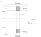
- FIG. 9-1 (a) is the specification of the sample used for adhesive strength measurement
- Figure 9-2 (b) is a finished drawing of the sample
- Figure 9-2 (c) is a diagram showing the adhesive strength measurement method. is. From FIG. 9-1(a), samples are obtained in the following manner. As the sheet P, GF-C081 sold by Canon Marketing Japan Inc. is used.
- the adhesive powder Tn is printed with a width of 4 cm from a position 2 cm on the leading end in the paper feed direction, and a width of 3 cm is printed in the center of the longitudinal direction to form a bonding area S1 indicated by oblique lines.
- the adhesive powder Tn is printed with a width of 4 cm from a position 2 cm on the rear end side in the paper feed direction, and a width of 3 cm is printed in the center of the longitudinal direction to form a bonding area S2 indicated by oblique lines.
- This is folded by folding means 31 shown in FIG. 1 and adhered by adhesion means 32 . As shown in Fig. 9-2(b), cut it so that the width is 3 cm and the total length is 14 cm from the leading edge of the pasted paper in the feeding direction.
- the paper end Q of the long non-bonded portion of the sample is supported with a chuck.
- a tensile test is performed at a tensile speed of 50 mm/min using an RTG-1225 Tensilon universal testing machine (not shown) manufactured by A&D Co., Ltd. to obtain a stress-strain curve.
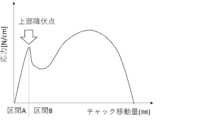
- Fig. 10 is an example of a stress-strain curve.
- the horizontal axis is the amount of movement of the chuck, and the vertical axis is the tensile stress per unit sample width.
- Section A is the section from the amount of movement 0 mm to the upper yield point, and section B is the section after that.
- Section A is an elastically deformable region, and no peeling of the adhesive region occurs. Therefore, the sample can retain its original shape when the pulling is stopped.
- section B is a plastically deformed area, and peeling of the bonded area or tearing of paper, which will be described later, occurs.
- the stress at the upper yield point per unit width is defined as adhesive force. If it continues to be pulled past the upper yield point, delamination of the bond begins to progress. In other words, it means that the bottom of the bag as a product starts to come off.
- M/S is the amount of powder applied per unit area on the developing roller 105 (hereinafter referred to as M/Sd), the peripheral speed ratio between the photosensitive drum 101 and the developing roller 105, and the transfer unit 3 from the photosensitive drum 101. , and the transfer efficiency from the transfer unit 3 to the sheet P (2).
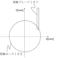
- FIG. 11 is a diagram showing the positions of the ends of the developing blade 107 with respect to the center of rotation of the developing roller 105.
- the X-axis controls the pressure with which the developer blade 107 contacts the developer roller 105 .
- the Y-axis controls the intake amount of powders Tn, Ty, Tm, and Tc.
- M/Sd is determined by which X, Y (hereinafter referred to as X value and Y value) the tip position of the developing blade 107 is set.
- Table 1 shows the relationship between the setting of the developing blade 107 (X value, Y value) and M/Sd in each developing device. At this time, the contact pressure of the developing blade 107 against the developing roller 105 was 30 N/cm.
- the adhesive image forming portion using the powder adhesive Tn has a larger M/Sd than the printing image forming portion using the printing toners Ty, Tm, and Tc by decreasing the Y value and increasing the uptake. ing.
- M/Sp the amount of M required to obtain a sufficient adhesive strength of the powder adhesive, rather than the amount of application per unit area on the sheet P (hereinafter referred to as M/Sp) required for visually recognizing the image of the printing toner.
- M/Sp the amount of powder adhesive present in the bonding area between recording media
- M/Stotal the amount of powder adhesive present in the bonding area between recording media
- the peripheral speed ratio between the photosensitive drum 101 and the developing roller 105 is 150%
- the transfer efficiency (1) from the photosensitive drum 101 to the transfer unit 3 is 97%
- the transfer efficiency to P was (2) 95%.
- a fogging evaluation method will be described. Since the powder adhesive Tn used in this example is transparent, quantification using a conventional reflection densitometer cannot be employed. The area ratio of the powder calculated from the observation photograph on the photosensitive drum 101 is used as an evaluation index. Specifically, the image forming apparatus 1 is stopped while printing a solid white image, and the solid white image formed on the photosensitive drum 101 in the area after passing through the developing roller 105 and before coming into contact with the transfer unit 3 . photo shoot. A VK-X200 shape measuring laser microscope manufactured by KEYENCE was used, and the images were taken at a magnification of 20 times. The captured image is analyzed using imageJ, which is software from Wayne Rasband.
- Photographs are captured, binarized, and displayed as a histogram.
- the ratio (%) of the area of the powder adhesive to the total area at this time is defined as the area ratio (%) of the powder adhesive. Therefore, there is a relationship that when fogging occurs, the powder adhesive area ratio increases.
- Table 2.2 Ranking was carried out according to the area ratio of the powder adhesive as described in the criteria for fog determination.
- Comparative example The main configuration is the same as that of the first embodiment.
- M/Sd was changed with respect to printing toners Ty, Tm, and Tc.
- the particle size was changed with respect to the printing toners Ty, Tm, and Tc.
- the formulation of external additives was changed.
- the contents of ester wax and hydrocarbon wax in Comparative Examples 1 to 5 are the same as in the printing toner. From the viewpoint of ensuring fluidity, silica was externally added in Example 1 and Comparative Examples 1 to 5.
- silica having an outer diameter several times larger than the silica used in Example 1 was externally added from the viewpoint of improving the transferability.
- the particle size of silica (number average particle size of primary particles) was 10 nm, and the particle size of large silica was 40 nm.
- the external addition of silica and the external addition of large silica was 1.5 parts with respect to 100 parts of toner particles.
- Table 3 The list of physical properties of each powder summarizes the amount of plasticizer, particle size, M/Sd, and presence/absence of external addition of large silica for printing toners Ty, Tm, and Tc, powder adhesive Tn, and each comparative example.
- the Y value of the comparative example was adjusted to the stated M/Sd.
- Example 1 Comparative Example
- Table 4 A comparison result list of Example 1 and Comparative Example is a comparison result list of Example 1 and Comparative Example. Table 4. The maximum adhesive strength described in 1 was taken as the maximum value when M/Stotal was changed.
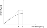
- FIG. 12 shows a comparison of M/Stotal and adhesive force.
- the vertical axis is the adhesive force [N/cm] per unit length in the longitudinal direction, and the horizontal axis is M/Stotal [mg/cm 2 ].
- the dashed line is the adhesive strength of Example 1, and the solid line is the adhesive strength of Comparative Examples 1-5.
- the adhesive strength increases as the contact area between the adhesive and the sheet P increases. In order to widen the contact area, the M/S may be increased, but even with the same M/S, the contact area can be widened by, for example, melting and spreading the powder adhesive Tn more.
- the printing toners Ty, Tm, and Tc are offset. Furthermore, since the M/S of the powder adhesive Tn is larger than that of the printing toners Ty, Tm, and Tc, the printing toners Ty, Tm, and Tc can be generated by simply applying heat to melt and spread the powder adhesive Tn. offset.
- the fixing temperature during secondary fixing by the adhesion means 32 was set to 200° C. from the viewpoint of suppressing the offset of the printing toners Ty, Tm, and Tc.
- the powder adhesive Tn can be improved in sharp-melt property and offset of the printing toner can be reduced. While suppressing this, the contact area of the powder adhesive Tn with the sheet P was increased, and the adhesive strength was improved.
- Example 1 has a larger amount of wax than printing toners Ty, Tm, Tc and Comparative Examples 1-5.
- the adhesive force can be improved more than Comparative Examples 1 to 5 with respect to changes in M/Total. This is because the powder adhesive Tn can be quickly melted by increasing the amount of wax, so the contact area between the regions 1 and 2 shown in FIG. 9-2(c) can be efficiently increased. This is thought to be because The reason why the adhesive strength is constant in the region of M/Stotal ⁇ X is that the sheet P is torn. Although the adhesive strength increases according to M/Total, since the upper yield point shown in FIG. 10 depends on the strength of the sheet P, the adhesive strength remains constant.
- Fogging is a phenomenon in which toner with a low triboelectricity (amount of charge) migrates to a dark potential portion on the photosensitive drum 101 .
- triboelectric charging from the developing roller 105 or the developing blade 107 causes toner to obtain triboelectricity. Therefore, the size of the tribo is affected by the number of occasions of rubbing with the developing roller 105 or the developing blade 107 .
- Comparative Example 1 has the same particle size as the printing toners Ty, Tm, and Tc, and has a high M/Sd by adjusting the Y value of the developing blade 107, for example, in order to obtain adhesive strength.
- the particle size is large, the number of powder layers can be reduced at the same M/Sd, and triboelectricity is easily imparted.
- the M/Sd is increased, if the effect of reducing the number of layers is exceeded, the chance of rubbing with the developing roller 105 or the developing blade 107 can be maintained, and sufficient triboelectricity can be imparted. Therefore, fogging can be suppressed.
- the M/Sd of the printing toner is M/SdA
- the M/Sd of the powder adhesive is M/SdB
- the volume of one particle calculated from the weight average particle size of the printing toner is Wt
- the powder adhesion By satisfying the following formula (4) where Wn is the volume of one particle calculated from the weight-average particle size of the agent, fogging can be suppressed while obtaining M/Stotal that provides sufficient adhesive strength. (M/SdB)/(M/SdA) ⁇ Wn/Wt Expression (4)
- the reason for this is that by achieving an increase in M/Sd by increasing the volume, the number of layers of powder in the regulating portion can be suppressed, sufficient opportunities for rubbing can be secured, and fogging can be suppressed.
- Example 1 fogging was good as described above.
- Comparative Example 1 since the particle diameters are the same as those of the printing toners Ty, Tm, and Tc, the number of layers of powder on the regulating portion of the developing blade 107 increased, the chances of rubbing decreased, and fogging occurred.
- the amount of powder adhesive applied (M/SdB) [mg/cm 2 ] is the first toner for developing the electrostatic latent image formed on the first image carrier (first photoreceptor) in the print image forming unit. It is preferably larger than the amount of printing toner per unit area (M/SdA) [mg/cm 2 ] on the developer carrier (on the first developing roller).
- the value of the ratio of the powder adhesive loading per unit area on the second developing roller (M/SdB) to the printing toner loading per unit area on the first developing roller (M/SdA) is preferably 1.05 to 3.00, more preferably 1.09 to 2.70.
- the amount of powder adhesive applied per unit area (M/SdB) [mg/cm 2 ] on the second developing roller is not particularly limited, but is preferably 0.55 to 0.80, more preferably 0.60 to 0.80.
- the amount of printing toner applied per unit area (M/SdA) [mg/cm 2 ] on the first developing roller is not particularly limited, but is preferably 0.30 to 0.55.
- ⁇ About scattering> Scattering occurs when the powder has a force to adhere to the photosensitive drum 101 or the transfer unit 3 (hereinafter referred to as adhesion force) and a force to be peeled off (hereinafter referred to as peeling force). Occurs when is greater than
- the peeling force includes, for example, centrifugal force received during driving and air resistance due to airflow.
- Examples of adhesive force include Van der Waals force and reflection force.
- Table 4 The evaluation of scattering in Table 4 is based on the occurrence of scattering inside the image forming apparatus and on the outer peripheral surface of the process cartridge when 10,000 sheets of vertical band images of 5 mm width are continuously printed under an environment of 23° C./50% RH. Judging by the presence or absence of
- large silica may be added externally to improve transfer efficiency.
- the large silica reduces the contact area between the powder adhesive Tn and the photosensitive drum 101 or the transfer unit 3, lowers the adhesive force, and improves the transfer efficiency.
- the weight average particle size of the powder adhesive Tn is preferably about 5 to 10 ⁇ m.
- Silica has, for example, a number average particle diameter of primary particles of preferably 5 nm or more and less than 30 nm, more preferably 7 to 20 nm, still more preferably 7 to 15 nm.
- the content of silica is preferably 0.1 to 10.0 parts by mass, more preferably 0.5 to 5.0 parts by mass, and more preferably 1.0 to 10.0 parts by mass with respect to 100 parts by mass of the toner particles. 3.0 parts by mass.
- the large silica has, for example, a number average particle diameter of primary particles of preferably 30 nm to 200 nm, more preferably 35 to 100 nm, still more preferably 35 to 50 nm.
- the content of the large silica is preferably 1.0 to 2.0 parts by mass, more preferably 1.0 to 1.5 parts by mass, based on 100 parts by mass of the toner particles. If it is 1.0 parts by mass or more, dripping due to insufficient triboelectricity can be suppressed. When the amount is 1.5 parts by mass or less, poor fixing can be suppressed.
- FIG. 13 shows a schematic diagram of an adhesive force measuring device.
- powder is attached to the tip of the horn 81 , and the charge is removed by an ionizer, and then the horn 81 is installed in the acceleration applying device 80 .
- Acceleration is applied to the horn 81 by the acceleration applying device 80 in the up-and-down direction in FIG.
- Observation images of the toner attached to the horn 81 before and after application of acceleration are obtained by the observation device 83, and the number and particle size of the scattered toner are calculated by an analysis device (not shown).
- the adhesive force is calculated from the applied acceleration and the particle size of the scattered powder. Specifically, the adhesive force is calculated by the following formula.
- Adhesive force F [nN] a ⁇ m a: Acceleration when toner scatters, m: Mass of toner (volume calculated from particle size multiplied by specific gravity (1.0 in this embodiment))
- FIG. 14 is a diagram showing the relationship between the weight average particle size of the powder adhesive Tn and the peeling force.
- the vertical axis is the force [nN] applied to the toner, and the horizontal axis is the weight average particle diameter [ ⁇ m].
- the curve of the thick solid line shows the peeling force obtained from the occurrence of scattering in this example.
- the horizontal solid line indicates the threshold for the occurrence of scattering when silica is added externally
- the thick horizontal dashed line indicates the threshold for occurrence of scattering when large silica is added externally. Scattering occurs when the peeling force exceeds the scattering generation threshold.
- the scattering occurrence threshold is determined by the magnitude of the adhesive force of the powder adhesive.
- the threshold value of the external addition of large silica is low is that the adhesive strength is low as described above.
- the weight average particle size of the powder adhesive Tn is preferably in the range of 5 ⁇ m to 20 ⁇ m.
- the powder adhesive Tn has a weight-average particle diameter of 5 ⁇ m to 5 ⁇ m in order to suppress scattering even in a state where the adhesive strength is reduced by adding large silica externally from the viewpoint of improving the transferability. 10 ⁇ m is more preferable.
- Example 1 and Comparative Examples 1 and 3 scattering was suppressed because of the external additive formulation and the weight average particle size of 5 to 20 ⁇ m.
- Comparative Example 5 large silica was externally added, but the weight average particle size was 5 to 10 ⁇ m, so scattering could be suppressed.
- Comparative Examples 2 and 4 scattering occurred because the adhesive force was smaller than the peeling force.
- the content of the plasticizer (eg, ester wax) contained in the powder adhesive is greater than the content of the plasticizer (eg, ester wax) in the printing toner.
- the powder adhesive has a weight average particle size of 5 to 20 ⁇ m. Also, more preferably, the weight average particle size of the powder adhesive is larger than the weight average particle size of the printing toner.
- FIG. 15 is a schematic diagram of an image forming apparatus according to the second embodiment.
- Example 2 it is possible to create a booklet in the post-processing step.
- a dotted arrow R3 indicates a conveying path of the sheet P.
- the sheet P is sent to the intermediate conveying means 60 .
- the sheet is conveyed to the post-processing device 62 by the intermediate conveying rollers 61 .
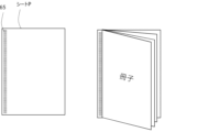
- FIG. 16 is a schematic diagram of a booklet-shaped product obtained from the configuration of Example 2.
- FIG. When creating a booklet, powder is printed on the powder adhesive Tn printing area 65 . By bonding the powder adhesive Tn printing area 65 with the secondary fixing device 64, a booklet product can be obtained.
- Example 1 In the comparative experiment conducted in Example 1, the fixing state in the secondary fixing device 64 was as good as in Example 1, so the results were the same. Therefore, by adopting the configuration of the second embodiment, it is possible to provide an image forming apparatus capable of obtaining a good booklet.
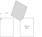
- FIG. 17 is a schematic diagram of an image forming apparatus according to the third embodiment.
- Example 3 it is possible to create a corner-stopped booklet in a post-processing step.
- the sheet P discharged from the image forming apparatus 1 passes through a route indicated by a dotted arrow R4. That is, after being conveyed to the post-processing device 66 , the sheet is conveyed to the discharge tray 68 by the conveying rollers 67 .
- a secondary fixing device 69 is provided above the discharge tray, and adheres the corners of the discharged sheet P. As shown in FIG.
- FIG. 18 is a schematic diagram of a corner-stopped booklet-shaped product obtained from the configuration of Example 3.
- FIG. 18 When creating a booklet for corner fixing, powder is printed on the powder adhesive Tn printing area 70 . By adhering the powder adhesive Tn printed area 70 with the secondary fixing device 69, a corner-stopping booklet product can be obtained.
- the printing toner contains a wax
- the powder adhesive contains wax
- the wax contained in the printing toner contains a plasticizer
- the wax contained in the powder adhesive contains a plasticizer
- the image forming apparatus according to Configuration Example 1 wherein the content of the plasticizer in the powder adhesive is higher than the content of the plasticizer in the printing toner.
- the plasticizer in the printing toner is an ester wax; the plasticizer in the powder adhesive is ester wax, The image forming apparatus according to Configuration Example 2, wherein the content of the ester wax in the powder adhesive is higher than the content of the ester wax in the printing toner.
- the powder adhesive has a weight average particle size larger than that of the printing toner.
- the first image forming unit includes a first image carrier and a first developer carrier for developing an electrostatic latent image formed on the first image carrier with the printing toner.
- the second image forming unit includes a second image carrier and a second developer carrier for developing an electrostatic latent image formed on the second image carrier with the powder adhesive.
- Structural Example 1 The amount of the powder adhesive applied per unit area on the second developer carrier is greater than the amount of the printing toner applied per unit area on the first developer carrier. 6.
- the image forming apparatus according to any one of 1 to 5.
- the adhesive cartridge comprises a second imaging station for imaging the powder adhesive with the powder adhesive;
- the powder adhesive contains wax,
- the wax contained in the printing toner contains a plasticizer,
- the wax contained in the powder adhesive contains a plasticizer,
- the plasticizer in the printing toner is an ester wax; the plasticizer in the powder adhesive is ester wax, The adhesive cartridge according to Configuration Example 8, wherein the content of the ester wax in the powder adhesive is higher than the content of the ester wax in the printing toner.
- the first image forming unit has a first developer bearing member for developing an electrostatic latent image formed on the first image bearing member with the printing toner
- the second image forming unit has a second developer carrier that develops an electrostatic latent image formed on the second image carrier with the powder adhesive
- Structural Example 7 The amount of the powder adhesive applied per unit area on the second developer carrier is greater than the amount of the printing toner applied per unit area on the first developer carrier.
- the adhesive container has a powder container for containing the powder adhesive,
- the powder adhesive contained in the powder container contains wax,
- An adhesive container, wherein the wax content in the powder adhesive is higher than the wax content in the printing toner.
- the wax contained in the printing toner contains a plasticizer
- the wax contained in the powder adhesive contains a plasticizer, 17.
- the plasticizer in the printing toner is an ester wax; the plasticizer in the powder adhesive is ester wax, 18.
- [Configuration example 20] 19 The adhesive container according to any one of configuration examples 16 to 19, wherein the powder adhesive has a weight average particle size larger than that of the printing toner.
Landscapes
- Physics & Mathematics (AREA)
- General Physics & Mathematics (AREA)
- Electrophotography Configuration And Component (AREA)
- Control Or Security For Electrophotography (AREA)
- Developing Agents For Electrophotography (AREA)
Priority Applications (1)
| Application Number | Priority Date | Filing Date | Title |
|---|---|---|---|
| US18/609,729 US20240241459A1 (en) | 2021-09-30 | 2024-03-19 | Image forming apparatus, adhesive cartridge, adhesive container, and process cartridge set |
Applications Claiming Priority (2)
| Application Number | Priority Date | Filing Date | Title |
|---|---|---|---|
| JP2021-160530 | 2021-09-30 | ||
| JP2021160530A JP2023050436A (ja) | 2021-09-30 | 2021-09-30 | 画像形成装置、接着剤カートリッジ、接着剤容器及びプロセスカートリッジセット |
Related Child Applications (1)
| Application Number | Title | Priority Date | Filing Date |
|---|---|---|---|
| US18/609,729 Continuation US20240241459A1 (en) | 2021-09-30 | 2024-03-19 | Image forming apparatus, adhesive cartridge, adhesive container, and process cartridge set |
Publications (1)
| Publication Number | Publication Date |
|---|---|
| WO2023053944A1 true WO2023053944A1 (ja) | 2023-04-06 |
Family
ID=85782454
Family Applications (1)
| Application Number | Title | Priority Date | Filing Date |
|---|---|---|---|
| PCT/JP2022/034218 Ceased WO2023053944A1 (ja) | 2021-09-30 | 2022-09-13 | 画像形成装置、接着剤カートリッジ、接着剤容器及びプロセスカートリッジセット |
Country Status (3)
| Country | Link |
|---|---|
| US (1) | US20240241459A1 (enExample) |
| JP (1) | JP2023050436A (enExample) |
| WO (1) | WO2023053944A1 (enExample) |
Families Citing this family (1)
| Publication number | Priority date | Publication date | Assignee | Title |
|---|---|---|---|---|
| JP2024101321A (ja) * | 2023-01-17 | 2024-07-29 | キヤノン株式会社 | シート接着装置 |
Citations (1)
| Publication number | Priority date | Publication date | Assignee | Title |
|---|---|---|---|---|
| JP2021102522A (ja) * | 2019-12-24 | 2021-07-15 | キヤノン株式会社 | 画像形成装置 |
Family Cites Families (1)
| Publication number | Priority date | Publication date | Assignee | Title |
|---|---|---|---|---|
| JP6818577B2 (ja) * | 2016-03-22 | 2021-01-20 | キヤノン株式会社 | 画像形成装置 |
-
2021
- 2021-09-30 JP JP2021160530A patent/JP2023050436A/ja active Pending
-
2022
- 2022-09-13 WO PCT/JP2022/034218 patent/WO2023053944A1/ja not_active Ceased
-
2024
- 2024-03-19 US US18/609,729 patent/US20240241459A1/en active Pending
Patent Citations (1)
| Publication number | Priority date | Publication date | Assignee | Title |
|---|---|---|---|---|
| JP2021102522A (ja) * | 2019-12-24 | 2021-07-15 | キヤノン株式会社 | 画像形成装置 |
Also Published As
| Publication number | Publication date |
|---|---|
| JP2023050436A (ja) | 2023-04-11 |
| US20240241459A1 (en) | 2024-07-18 |
Similar Documents
| Publication | Publication Date | Title |
|---|---|---|
| US11960225B2 (en) | Image forming apparatus | |
| US20220035261A1 (en) | Electrophotographic developer set comprising toner and powder adhesive, method for producing bonded product, and powder adhesive | |
| JP2021102522A (ja) | 画像形成装置 | |
| JP3825934B2 (ja) | 静電荷像現像用トナー及び画像形成方法 | |
| JP2006208431A (ja) | トナー、トナーの使用方法、トナー補給装置及び画像形成装置 | |
| US20240241459A1 (en) | Image forming apparatus, adhesive cartridge, adhesive container, and process cartridge set | |
| JP5344552B2 (ja) | トナーおよびトナーの製造方法 | |
| US12405561B2 (en) | Press-bonded sheet manufacturing method, press-bonded sheet manufacturing apparatus, and image forming apparatus | |
| WO2023054311A1 (ja) | 圧着シート製造方法及び画像形成装置 | |
| JP2016166936A (ja) | トナー収容容器、及び画像形成装置 | |
| JP2010117617A (ja) | 現像剤、現像剤カートリッジ、現像装置及び画像形成装置 | |
| US11840417B2 (en) | Sheet bonding apparatus | |
| JP7562349B2 (ja) | 画像形成装置 | |
| JP2016170336A (ja) | トナー収容容器、及び画像形成装置 | |
| JP6443147B2 (ja) | トナー収容容器、及び画像形成装置 | |
| JP2024040063A (ja) | トナーセット、静電荷像現像剤セット、トナーカートリッジセット、プロセスカートリッジ、画像形成装置、及び、画像形成方法 | |
| JP2023051791A (ja) | 圧着シート製造方法及び画像形成装置 | |
| JP2000235277A (ja) | 乾式トナー及び画像形成方法 | |
| JP7556004B2 (ja) | 圧着シート製造方法 | |
| US12372910B2 (en) | Image forming apparatus having sheet bonding apparatus | |
| JP2002287403A (ja) | 静電荷像現像用トナー、その製造方法、画像形成方法及び画像形成装置 | |
| JP2023051022A (ja) | 画像形成装置 | |
| JP3880261B2 (ja) | 乾式トナー及び画像形成方法 | |
| JP2007140139A (ja) | 現像剤供給装置及び現像剤 | |
| JP2003131414A (ja) | 現像装置、画像形成装置、トナー、トナーの検査方法、及び、コンピュータシステム |
Legal Events
| Date | Code | Title | Description |
|---|---|---|---|
| 121 | Ep: the epo has been informed by wipo that ep was designated in this application |
Ref document number: 22875816 Country of ref document: EP Kind code of ref document: A1 |
|
| NENP | Non-entry into the national phase |
Ref country code: DE |
|
| 122 | Ep: pct application non-entry in european phase |
Ref document number: 22875816 Country of ref document: EP Kind code of ref document: A1 |