WO2023053781A1 - 画像処理装置、方法及びプログラム - Google Patents
画像処理装置、方法及びプログラム Download PDFInfo
- Publication number
- WO2023053781A1 WO2023053781A1 PCT/JP2022/031749 JP2022031749W WO2023053781A1 WO 2023053781 A1 WO2023053781 A1 WO 2023053781A1 JP 2022031749 W JP2022031749 W JP 2022031749W WO 2023053781 A1 WO2023053781 A1 WO 2023053781A1
- Authority
- WO
- WIPO (PCT)
- Prior art keywords
- image
- imaging
- information
- unit
- image processing
- Prior art date
- Legal status (The legal status is an assumption and is not a legal conclusion. Google has not performed a legal analysis and makes no representation as to the accuracy of the status listed.)
- Ceased
Links
Images






Classifications
-
- G—PHYSICS
- G06—COMPUTING OR CALCULATING; COUNTING
- G06V—IMAGE OR VIDEO RECOGNITION OR UNDERSTANDING
- G06V20/00—Scenes; Scene-specific elements
- G06V20/50—Context or environment of the image
-
- G—PHYSICS
- G06—COMPUTING OR CALCULATING; COUNTING
- G06T—IMAGE DATA PROCESSING OR GENERATION, IN GENERAL
- G06T7/00—Image analysis
-
- E—FIXED CONSTRUCTIONS
- E01—CONSTRUCTION OF ROADS, RAILWAYS, OR BRIDGES
- E01D—CONSTRUCTION OF BRIDGES, ELEVATED ROADWAYS OR VIADUCTS; ASSEMBLY OF BRIDGES
- E01D22/00—Methods or apparatus for repairing or strengthening existing bridges ; Methods or apparatus for dismantling bridges
-
- G—PHYSICS
- G06—COMPUTING OR CALCULATING; COUNTING
- G06T—IMAGE DATA PROCESSING OR GENERATION, IN GENERAL
- G06T7/00—Image analysis
- G06T7/0002—Inspection of images, e.g. flaw detection
-
- G—PHYSICS
- G06—COMPUTING OR CALCULATING; COUNTING
- G06V—IMAGE OR VIDEO RECOGNITION OR UNDERSTANDING
- G06V10/00—Arrangements for image or video recognition or understanding
- G06V10/70—Arrangements for image or video recognition or understanding using pattern recognition or machine learning
- G06V10/764—Arrangements for image or video recognition or understanding using pattern recognition or machine learning using classification, e.g. of video objects
-
- G—PHYSICS
- G06—COMPUTING OR CALCULATING; COUNTING
- G06V—IMAGE OR VIDEO RECOGNITION OR UNDERSTANDING
- G06V20/00—Scenes; Scene-specific elements
- G06V20/50—Context or environment of the image
- G06V20/52—Surveillance or monitoring of activities, e.g. for recognising suspicious objects
-
- G—PHYSICS
- G06—COMPUTING OR CALCULATING; COUNTING
- G06T—IMAGE DATA PROCESSING OR GENERATION, IN GENERAL
- G06T2207/00—Indexing scheme for image analysis or image enhancement
- G06T2207/30—Subject of image; Context of image processing
- G06T2207/30181—Earth observation
- G06T2207/30184—Infrastructure
-
- G—PHYSICS
- G06—COMPUTING OR CALCULATING; COUNTING
- G06T—IMAGE DATA PROCESSING OR GENERATION, IN GENERAL
- G06T2207/00—Indexing scheme for image analysis or image enhancement
- G06T2207/30—Subject of image; Context of image processing
- G06T2207/30244—Camera pose
-
- G—PHYSICS
- G06—COMPUTING OR CALCULATING; COUNTING
- G06V—IMAGE OR VIDEO RECOGNITION OR UNDERSTANDING
- G06V10/00—Arrangements for image or video recognition or understanding
- G06V10/70—Arrangements for image or video recognition or understanding using pattern recognition or machine learning
- G06V10/82—Arrangements for image or video recognition or understanding using pattern recognition or machine learning using neural networks
-
- G—PHYSICS
- G06—COMPUTING OR CALCULATING; COUNTING
- G06V—IMAGE OR VIDEO RECOGNITION OR UNDERSTANDING
- G06V20/00—Scenes; Scene-specific elements
- G06V20/95—Pattern authentication; Markers therefor; Forgery detection
Definitions
- the present invention relates to an image processing device, method and program, and more particularly to an image processing device, method and program for processing an image of a structure such as a bridge.
- Structures such as bridges, roads, tunnels and dams are developed as the foundation of industry and life, and play an important role in supporting the comfortable lives of people.
- Such structures are built using, for example, concrete, steel frames, etc., but they are used by people for a long period of time, so they deteriorate over time. Therefore, it is necessary to inspect such structures in a timely manner to discover where damage and deterioration have occurred, and to perform appropriate maintenance such as replacement or repair of members.
- Patent Document 1 discloses an inspection system that images bridge girders and the like using a hovering camera that is configured to automatically fly according to preset flight information. It is According to Patent Literature 1, by automatically flying a hovering camera to capture images of bridge girders, etc., it is possible to inspect bridges at low cost without affecting traffic.
- an inspector can visually check the images and classify and organize the images by the members that make up the structure. Also, a correspondence relationship between design data or a three-dimensional model (hereinafter referred to as a 3D model) containing information about the structure of the structure to be imaged and the imaging position of the image is obtained, and the image is classified and classified using this correspondence relationship. It is conceivable to organize design data or a three-dimensional model (hereinafter referred to as a 3D model) containing information about the structure of the structure to be imaged and the imaging position of the image is obtained, and the image is classified and classified using this correspondence relationship. It is conceivable to organize design data or a three-dimensional model (hereinafter referred to as a 3D model) containing information about the structure of the structure to be imaged and the imaging position of the image is obtained, and the image is classified and classified using this correspondence relationship. It is conceivable to organize design data or a three-dimensional model (hereinafter referred to as a 3D model) containing information about the structure
- an image processing apparatus includes a member discrimination unit that discriminates a member appearing in a discrimination target structure image obtained by imaging a structure, and a member discrimination unit. and an identification information adding unit that adds member identification information indicating the determined member to the structure image to be determined.
- the member determination unit performs image recognition of the structure image to be determined, and based on the result of the image recognition, the structure to be determined Identify the parts shown in the image.
- the member determination unit includes a member determination AI that has learned about determination of members constituting a structure, and uses the member determination AI to determine the object to be determined. The members appearing in the structure image of are discriminated.
- the member determination unit detects a member identifier attached to each member constituting the structure from the structure image to be determined, The members appearing in the structure image to be identified are identified using the member identifiers.
- the member identification unit performs image recognition of a structure image to which member identification information has already been assigned and a structure image to be identified. , the member appearing in the structure image to be determined is determined based on the result of the image recognition.
- the member determination unit is a structure model including information indicating the structure of the structure, and is associated with the member identification information of the structure.
- a structure model and a reference structure image associated with the structure model are acquired, image recognition is performed on the reference structure image and the structure image to be discriminated, and discrimination is performed based on the result of image recognition.
- the member determination unit acquires reference information for determining a member appearing in the structure image to be determined, and uses the reference information as Based on this, the member appearing in the structure image to be determined is determined.
- the reference information includes a structure model including information indicating the structure of the structure, and an imaging position when the structure image to be determined is captured. and information on the imaging situation including information on the imaging direction, and the member discriminating unit discriminates the members appearing in the structure image to be discriminated based on the correspondence relationship between the structure model and the information on the imaging situation. do.
- the reference information includes information indicating the correspondence relationship between the imaging order of the structure images to be determined and the members constituting the structure.
- the structure image includes information about the imaging plan of the structure, and the member determination unit determines a member appearing in the structure image to be determined based on the correspondence relationship between the information about the imaging plan and the structure image to be determined.
- An image processing device is the ninth aspect, wherein the information about the imaging plan includes information indicating the imaging position and imaging direction at the time of imaging the structure, and the image processing device,
- the imaging unit for imaging the structure, the positioning unit for measuring the imaging position and imaging direction of the imaging unit, and the imaging position and imaging direction of the imaging unit indicate the imaging position and imaging direction included in the information on the imaging plan. and a control unit that controls to match the information.
- An image processing device is the image processing device according to any one of the first to tenth aspects, wherein when a plurality of members appear in the structure image to be determined, the identification information providing unit adds a plurality of member identification information relating to the members of is given to the structure image to be determined.
- An image processing apparatus in any one of the first to eleventh aspects, includes a damage information adding unit that detects damage from the structure image and adds information about the damage to the structure image. Prepare.
- An image processing apparatus in any one of the first to twelfth aspects, includes an attached information editing unit for editing attached information attached to the structure image.
- An image processing apparatus in any one of the first to thirteenth aspects, further comprises a structure image search unit that searches for a structure image based on attached information attached to the structure image. .
- An image processing method includes a step of determining a member appearing in a structure image to be determined, which is an image of a structure; and adding member identification information indicating the member to the structure image to be determined.
- An image processing program includes a member discrimination function for discriminating a member appearing in a structure image to be discriminated, which is an image of a structure, and member identification information indicating the member discriminated by the member discrimination function. to the structure image to be identified.
- each of the above aspects can also be realized as an image processing device for a processor of a computer to realize the functions of the above units. That is, the processor of the image processing device discriminates the member appearing in the structure image to be discriminated by imaging the structure, and adds the member identification information indicating the discriminated member to the structure image to be discriminated. It is also possible to
- the present invention it is possible to easily classify and organize structure images by distinguishing members appearing in structure images and adding member identification information to the structure images.
- FIG. 1 is a block diagram showing an image processing apparatus according to the first embodiment of the invention.
- FIG. 2 is a diagram for explaining image processing functions according to the first embodiment of the present invention.
- FIG. 3 is a flowchart showing an image processing method according to the first embodiment of the invention.
- FIG. 4 is a flow chart showing the member determination process (step S12 in FIG. 3) according to the first embodiment of the present invention.
- FIG. 5 is a diagram for explaining image processing functions according to the second embodiment of the present invention.
- FIG. 6 is a flow chart showing the member determination process (step S12 in FIG. 3) according to the second embodiment of the present invention.
- FIG. 7 is a diagram for explaining image processing functions according to the third embodiment of the present invention.
- FIG. 1 is a block diagram showing an image processing apparatus according to the first embodiment of the invention.
- FIG. 2 is a diagram for explaining image processing functions according to the first embodiment of the present invention.
- FIG. 3 is a flowchart showing an image processing method according to the
- FIG. 8 is a perspective view showing a specific example of a structure model.
- FIG. 9 is an enlarged plan view of region IX in FIG. 8 as seen from below.
- 10 is a perspective view showing an enlarged region X of FIG. 8.
- FIG. 11 is a diagram for explaining member determination using a structure image associated with the structure in FIG. 10.
- FIG. 12 is a flow chart showing the member determination process (step S12 in FIG. 3) according to the third embodiment of the present invention.
- FIG. 13 is a diagram for explaining image processing functions according to the fourth embodiment of the present invention.
- FIG. 14 is a diagram for explaining member determination using information about a structure model and an imaging situation.
- FIG. 15 is a flow chart showing the member determination process (step S12 in FIG. 3) according to the fourth embodiment of the present invention.
- FIG. 16 is a diagram for explaining image processing functions according to the fifth embodiment of the present invention.
- FIG. 17 is a diagram for explaining member determination using information about a structure model and an imaging plan.
- FIG. 18 is a flow chart showing the member determination process (step S12 in FIG. 3) according to the fifth embodiment of the present invention.
- FIG. 19 is a block diagram illustrating image processing functionality according to additional embodiments.
- FIG. 20 is a block diagram showing an imaging device having an image processing function according to Modification 1.
- FIG. 21 is a block diagram showing a cloud server having an image processing function according to Modification 2.
- FIG. 20 is a block diagram showing an imaging device having an image processing function according to Modification 1.
- FIG. 21 is a block diagram showing a cloud server having an image processing function according to Modification 2.
- FIG. 20 is a block diagram showing an imaging device having an image processing function according to Modification 1.
- FIG. 21 is a block diagram showing a cloud server having an image processing function according to Modification 2.
- FIG. 1 is a block diagram showing an image processing apparatus according to the first embodiment of the invention.
- the image processing device 10 is a device for acquiring, from the imaging device 50, the structure image D1 obtained by imaging each part of the structure OBJ to be inspected, and classifying and organizing the structure images D1.
- the imaging device 50 includes a camera (for example, a CCD (Charge Coupled Device) camera or an infrared camera) for capturing an image of each part of the structure OBJ to be inspected.
- the imaging device 50 may be, for example, an unmanned aerial vehicle such as a multi-copter or a drone, a vehicle, or a moving body such as a robot, which is equipped with a camera, and may be capable of capturing an image while moving around the structure OBJ to be inspected. .
- the image processing apparatus 10 includes a control unit 12, an input unit 14, a display unit 16, a storage 18, and a communication interface (communication I/F) 20.
- the image processing apparatus 10 may be, for example, a general-purpose computer such as a personal computer or workstation, or a tablet terminal.
- the control unit 12 includes a processor (for example, CPU (Central Processing Unit) or GPU (Graphics Processing Unit)) that controls the operation of each unit of the image processing device 10 .
- the control unit 12 can transmit and receive control signals and data to and from each unit of the image processing apparatus 10 via a bus.
- the control unit 12 receives an instruction input from the operator via the input unit 14 and transmits a control signal corresponding to the instruction input to each unit of the image processing apparatus 10 via the bus to control the operation of each unit.
- the control unit 12 has a RAM (Random Access Memory) used as a work area for various calculations, and a VRAM (Video Random Access Memory) used as an area for temporarily storing image data output to the display unit 16. contains.
- RAM Random Access Memory
- VRAM Video Random Access Memory
- the input unit 14 is an input device that receives instructions input from the operator, and includes a keyboard for character input, etc., and a pointing device for operating a GUI (Graphical User Interface) such as a pointer and icons displayed on the display unit 16. Includes devices (eg, mouse, trackball, etc.). As the input unit 14 , a touch panel may be provided on the surface of the display unit 16 instead of or in addition to the keyboard and pointing device.
- GUI Graphic User Interface
- the display unit 16 is a device for displaying images.
- a liquid crystal monitor can be used as the display unit 16.
- the storage 18 stores various data including a control program and an image processing program P1 for various calculations, and a structure image D1 (for example, a visible light image or an infrared image) obtained by imaging the structure OBJ to be inspected. do.
- a structure image D1 for example, a visible light image or an infrared image
- a device including a magnetic disk such as HDD (Hard Disk Drive), a device including flash memory such as eMMC (embedded Multi Media Card) or SSD (Solid State Drive), etc. can be used.
- the communication I/F 20 is means for communicating with external devices including the imaging device 50 via a network.
- Wired communication or wireless communication for example, LAN (Local Area Network), WAN (Wide Area Network), Internet connection, etc.
- LAN Local Area Network
- WAN Wide Area Network
- Internet connection etc.
- the image processing device 10 can receive an input of the structure image D1 from the imaging device 50 via the communication I/F 20.
- the method of inputting the structure image D1 to the image processing device 10 is not limited to communication via a network.
- a USB (Universal Serial Bus) cable, Bluetooth (registered trademark), infrared communication, etc. may be used, and the structure image D1 may be stored in a recording medium (for example, a USB memory) that can be attached to and detached from the image processing device 10 and read.
- the structure image D1 may be stored and input of the structure image D1 may be accepted via this recording medium.
- FIG. 2 is a diagram for explaining the image processing function.
- the processor of the control unit 12 can realize the functions of the member determination unit 120 and the identification information provision unit 122 by reading out the image processing program P1 from the storage 18 and executing it.
- the member discrimination section 120 includes a member discrimination AI 120A (Artificial Intelligence).
- the member discrimination unit 120 performs image recognition or image analysis of the structure image D1 using the member discrimination AI 120A, and discriminates members constituting the structure OBJ shown in the structure image D1.
- the member discrimination AI 120A receives, for example, an image of a part of a structure OBJ such as a bridge, and uses teacher data whose output is the name of the member to learn the relationship between the input and output data. It is created by learning (for example, a classifier).
- the learning algorithm of the member discrimination AI 120A is not limited to supervised learning, and may be unsupervised learning.
- the image used for learning the member discrimination AI 120A does not need to be the image of the same structure OBJ as the inspection target.
- Images used for learning of the member discrimination AI 120A can be, for example, images of similar or similar structures OBJ, or images created using design data (e.g., three-dimensional models) of structure OBJs. is.
- the identification information adding unit 122 acquires the identification result of the member shown in the structure image D1 from the member identification unit 120, and adds the member identification information D2 to the structure image D1.
- the member identification information D2 includes, for example, the types of members constituting the structure OBJ (hereinafter referred to as member types) and identifiers for specifying members in the structure OBJ (hereinafter referred to as member IDs (Identification)). ).
- the member type is for classifying the members that make up the structure OBJ based on their shape, function, material, size, etc.
- the member types are main girders, cross girders, bridge piers, floor slabs, and the like.
- a member ID is an identifier for specifying which part the members that make up the structure OBJ are used for.
- the member ID may be defined as, for example, main girder A-1 for one of the plurality of main girders used for position A, or may be defined as specific position coordinates (for example, design positional coordinates of the center of gravity or positional coordinates of the edge).
- a structure OBJ may be configured by combining multiple members of the same type with the same member type. Therefore, by using the member identification information D2, which is a combination of the member type and the member ID, it is possible to specify the type and arrangement of the member appearing in the structure image D1. If the member ID includes information on the member type and arrangement as in the main girder A-1 exemplified above, only the member ID may be used as the member identification information D2.
- the member identification information D2 can be stored in Exif information, for example, when the structure image D1 is an Exif (Exchangeable Image File Format) file. Specifically, the member identification information D2 is, for example, among the Exif information, MakerNote, which is a tag for the maker to enter individual information and use it independently, or UserComment. It can be stored in association with tags related to operator information. The member identification information D2 can also be stored in an Exif file by adding a unique application marker segment (APPn), for example.
- APPn application marker segment
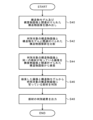
- FIG. 3 is a flowchart showing an image processing method according to the first embodiment of the invention.
- control unit 12 reads the structure image D1 acquired from the imaging device 50 from the storage 18 (step S10).
- the member discrimination unit 120 performs image recognition of the discrimination target structure image D1 read in step S10, and discriminates the members constituting the structure OBJ shown in the structure image D1 (step S12). ).
- step S12 first, as shown in FIG. 4, the member discrimination section 120 performs image recognition of the structure image D1 using the member discrimination AI 120A, and constructs the structure OBJ shown in the structure image D1. The member is discriminated (step S20). Then, the member discrimination section 120 outputs the member discrimination result to the identification information provision section 122 (step S22).
- the identification information adding unit 122 acquires the identification result of the member shown in the structure image D1 from the member identification unit 120, and adds the member identification information to the structure image D1 (step S14).
- steps S12 to S14 are repeatedly executed until discrimination of all structure images D1 is completed (step S16).
- the member identification information D2 can be added to the structure image D1 by performing image recognition of the structure image D1 using the member discrimination AI 120A. This makes it possible to easily classify and organize the structure images D1.
- the member identification information D2 is stored in the data (Exif information) of the structure image D1 in this embodiment, the present invention is not limited to this.
- the member identification information is stored in the viewing application for the structure image D1, and when the structure image D1 is viewed using the viewing application, the member identification information is stored.
- Information D2 may be displayable.
- the structure image D1 and the member identification information D2 may not have a one-to-one correspondence. That is, when a plurality of members are detected from the structure image D1, the member identification information D2 regarding the plurality of members may be stored in the structure image D1.
- the member identification information D2 may be divided into main members and minor members.
- the position in the structure image D1 or the area occupied in the structure image D1 can be used as a criterion for determining whether or not it is a main member.
- the member that appears closest to the center of the field of view of the structure image D1, or the member that occupies the largest area in the structure image D1 may be the main member.
- the member may be a minor member, or may not be included in the member identification information D2.
- the member discrimination AI 120A is used to perform image recognition of the structure image D1, but the present invention is not limited to this.
- member identifiers member identification marks, such as one-dimensional codes, two-dimensional codes, or QR (Quick Response) codes (registered trademark)
- a member identification mark defined for each member of the structure OBJ is affixed to each member of the structure OBJ.
- the storage 18 stores a lookup table showing the correspondence between member identification marks and members.
- the member discrimination unit 120 by detecting the member identification mark from the structure image D1 using image recognition by the member discrimination unit 120, it is possible to discriminate the member.
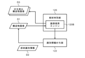
- FIG. 5 is a diagram for explaining image processing functions according to the second embodiment of the present invention.
- the member determination unit 120 can refer to the assigned structure image D3 to which the member identification information D2 has already been assigned as reference information. Then, the member discrimination unit 120 compares (matches) the structure image D1 to be discriminated with the added structure image D3, thereby discriminating the members constituting the structure OBJ shown in the structure image D1. do.
- the given structure image D3 may be stored in the storage 18 of the image processing apparatus 10, or may be stored in an external storage accessible by the image processing apparatus 10 (for example, cloud storage). good too.
- the member determination unit 120 includes an image search engine 120B.
- the member discriminating unit 120 uses the image search engine 120B to perform image recognition of the structure image D1 to be discriminated, and searches for an image showing the same member from the given structure images D3.
- the image search engine 120B extracts feature points from the structure image D1 to be determined, performs matching with the feature points extracted from each image of the attached structure image D3, and extracts the feature points from the structure image D3. Search for images showing the same member from among the images. Then, the member discrimination unit 120 discriminates members constituting the structure OBJ shown in the structure image D1 by reading out the member identification information D2 of the image retrieved from the given structure image D3.
- a similar image search engine using machine learning or deep learning can also be used as the image search engine 120B.
- the identification information adding unit 122 acquires the identification result of the member shown in the structure image D1 from the member identification unit 120, and adds the member identification information D2 to the structure image D1.
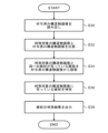
- FIG. 6 is a flow chart showing the member determination process (step S12 in FIG. 3) according to the second embodiment of the present invention.
- the control unit 12 reads out the attached structure image D3 from the storage 18 or the external storage (step S30).
- the given structure image D3 may be an image of the structure OBJ to be inspected, or an image of a structure of the same type or similar to the structure OBJ to be inspected.
- the member determination unit 120 uses the image search engine 120B to perform image recognition of the structure image D1 to be determined, and compares the structure image D1 with the given structure image D3 (step S32). Then, the member discriminating unit 120 searches for an image including the same members as the structure image D1, from among the assigned structure images D3 (step S34).
- the member identification unit 120 reads out the member identification information D2 of the image retrieved from the attached structure image D3, thereby identifying members constituting the structure OBJ shown in the structure image D1 (step S36).
- the member determination unit 120 outputs the member determination result to the identification information provision unit 122 (step S38). Thereby, member identification information can be added to the structure image D1 (step S14 in FIG. 3).
- the member identification information D2 can be assigned to the structure image D1 by referring to the assigned structure image D3 to which the member identification information D2 has already been assigned. This makes it possible to easily classify and organize the structure images D1.
- FIG. 7 is a diagram for explaining image processing functions according to the third embodiment of the present invention.
- the member determination unit 120 includes an image search engine 120C.
- the member determination unit 120 can refer to the structure model D41 to which the member identification information D2 is attached and the reference structure image D42 associated with the structure model D41 as reference information.
- the member discrimination unit 120 uses the image search engine 120C to refer to the structure image D1 to be discriminated, the structure model D41, and the reference structure image D42, thereby identifying the structure shown in the structure image D1.
- the members constituting the object OBJ are discriminated.
- the structure model D41 is data containing information on the shape and structure of the structure OBJ to be inspected, for example, a three-dimensional model containing information on the three-dimensional shape of the structure OBJ to be inspected.
- the structure model D41 may be design data of the structure OBJ to be inspected, or may be actual measurement data measured in advance.
- CAD Computer-Aided Design
- three-dimensional CAD data can be used.
- point cloud data in which the three-dimensional shape is restored from multi-viewpoint images of the structure OBJ using SfM (Structure from Motion) technology.
- the structure model D41 is provided with member identification information D2 for each member constituting the structure OBJ.
- This member identification information D2 is stored in the structure model D41 in association with the coordinates of the CAD data or the point group of the point group data.
- the reference structure image D42 is an image obtained by imaging the structure OBJ, and is stored in association with the position coordinates of the structure OBJ in the structure model D41.
- the structure model D41 and the reference structure image D42 may be stored in the storage 18 of the image processing device 10, or may be stored in an external storage accessible by the image processing device 10 (for example, cloud storage). may be stored in
- FIG. 8 illustrates specific examples of the structure model D41 and the reference structure image D42.
- FIG. 8 is a perspective view showing a specific example of a structure model
- FIG. 9 is an enlarged plan view of area IX in FIG. 8 as seen from below. 8 and 9 show a three-dimensional model D41 (OBJ1) of a bridge OBJ1 as a specific example of the structure OBJ.
- OBJ1 three-dimensional model D41
- member identification information D2 is assigned to each member that constitutes the bridge OBJ1.
- the reference structure image D42 is associated with each part of the three-dimensional model D41 (OBJ1).
- the member type and the member ID are illustrated as the member identification information D2, but the member type can be omitted if the member ID includes information on the member type. .
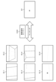
- FIG. 10 is an enlarged perspective view showing the region X (pier OBJ2) in FIG. 8, and FIG. 11 explains member determination using a reference structure image D42 associated with the structure OBJ2 in FIG. It is a figure for doing.
- FIG. 10 shows an overall image of a bridge pier OBJ2 that is a part of the bridge OBJ1
- FIG. 11 shows structure images corresponding to areas XI-1 to XI-6 in FIG. . Note that the imaging direction of the reference structure image D42 shown in FIG. 11 may be different from the overall image shown in FIG.
- the member determination unit 120 uses the image search engine 120C to perform image recognition of the structure image D1 to be determined, and the same member is captured in the reference structure image D42. Search for images that have
- the image search engine 120C extracts feature points from the structure image D1 to be determined, performs matching with the feature points extracted from each image of the reference structure image D42, and performs matching with the feature points extracted from each image of the reference structure image D42.
- An image in which the same member is photographed is retrieved from the image D42.
- the member identification unit 120 reads out the member identification information D2 of the structure model D41 associated with the image retrieved from the reference structure image D42, thereby recognizing the structure OBJ shown in the structure image D1. Identify the constituent members.
- a similar image search engine using machine learning or deep learning can also be used as the image search engine 120C.
- the identification information adding unit 122 acquires the identification result of the member shown in the structure image D1 from the member identification unit 120, and adds the member identification information D2 to the structure image D1.
- FIG. 12 is a flow chart showing the member determination process (step S12 in FIG. 3) according to the third embodiment of the present invention.
- the control unit 12 reads out the structure model D41 and the reference structure image D42 from the storage 18 or external storage (step S40).
- the structure model D41 and the reference structure image D42 may be the structure model D41 and the reference structure image D42 created for the structure OBJ to be inspected, or may be the structure OBJ to be inspected.
- a structure model D41 and a reference structure image D42 created for the same or similar structure may be used.
- the member discrimination unit 120 uses the image search engine 120C to perform image recognition of the structure image D1 to be discriminated, and obtains the structure image D1 and the reference structure image associated with the structure model D41. D42 is compared (step S42). Then, the member determination unit 120 searches the reference structure image D42 for an image showing the same member as the structure image D1 (step S44).
- the member identification unit 120 reads the member identification information D2 of the structure model D41 associated with the image retrieved from the reference structure image D42, and determines the structure OBJ shown in the structure image D1. is discriminated (step S46).
- the member identification unit 120 outputs the member identification result to the identification information provision unit 122 (step S48). Thereby, member identification information can be added to the structure image D1 (step S14 in FIG. 3).
- the member identification information D2 can be assigned to the structure image D1 by referring to the structure model D41 and the reference structure image D42 to which the member identification information D2 has already been assigned. This makes it possible to easily classify and organize the structure images D1.
- FIG. 13 is a diagram for explaining image processing functions according to the fourth embodiment of the present invention.
- the member determination unit 120 includes an imaging target calculation unit 120D.
- the member determination unit 120 can refer to the structure model D5 and the information D6 regarding the imaging state of the structure image D1 as reference information.
- the member determination unit 120 is reflected in the structure image D1 based on the correspondence relationship between the structure model D5 and the information D6 regarding the imaging situation including the imaging position and imaging direction of the structure image D1. Determine the parts.
- the structure model D5 is data containing information on the shape and structure of the structure OBJ to be inspected, for example, a three-dimensional model containing information on the three-dimensional shape of the structure OBJ to be inspected.
- the structure model D5 may be design data of the structure OBJ to be inspected, or may be actual measurement data measured in advance.
- CAD data or three-dimensional CAD data can be used as the structure model D5.
- point cloud data in which the three-dimensional shape is restored from multi-viewpoint images of the structure OBJ using SfM technology.
- the structure model D5 is provided with member identification information D2 for each member that constitutes the structure OBJ.
- This member identification information D2 is stored in the structure model D5 in association with the coordinates of the CAD data or the point cloud of the point cloud data.
- the information D6 about the imaging situation is information about the imaging situation when the structure image D1 was captured.
- the information D6 about the imaging situation includes, for example, information indicating the position of the imaging device 50 at the time of imaging (hereinafter referred to as imaging position) and information indicating the orientation of the imaging device 50 at the time of imaging (hereinafter referred to as imaging direction). contains.
- the information D6 regarding the imaging situation is measured by a positioning unit including, for example, a GPS (Global Positioning System) device, an inertial sensor, and an altitude sensor provided in the imaging device 50 .
- GPS Global Positioning System
- the information D6 about the imaging situation may be included in the structure image D1 as attached information (eg, Exif information) of the structure image D1, or may be included in the structure image D1 as a separate file associated with the structure image D1. may be obtained from
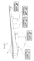
- FIG. 14 is a diagram for explaining member discrimination using the structure model D5 and the information D6 regarding the imaging situation.
- FIG. 14 illustrates an example using a three-dimensional model D5 (OBJ1) of a bridge OBJ1 (see FIG. 8) as the structure model D5.
- OBJ1 three-dimensional model D5
- FIG. 8 illustrates an example using a three-dimensional model D5 (OBJ1) of a bridge OBJ1 (see FIG. 8) as the structure model D5.
- the information D6 regarding the imaging situation includes information regarding the imaging position and the imaging direction.
- the imaging position is represented, for example, by an xyz three-dimensional orthogonal coordinate system.
- the imaging position may be represented by coordinates specified by latitude and longitude based on GPS (for example, global coordinates), or may be represented by local coordinates based on a predetermined position of the bridge OBJ1. .
- the imaging direction is represented, for example, by an abc three-dimensional orthogonal coordinate system with the imaging position as the origin and the camera provided in the imaging device 50 as a reference.
- FIG. 14 in the three-dimensional model D5 (OBJ1) of the bridge OBJ1, points indicating the imaging positions corresponding to the respective captured images (structure images) IMG1 to IMG4, arrows indicating the imaging direction, and rectangles indicating the imaging range are illustrated. ing. Note that the imaging range will be described later.
- an imaging direction vector extending along the imaging direction is defined with the imaging position included in the information D6 on the imaging situation as a starting point.
- the member determination unit 120 uses the imaging target calculation unit 120D to calculate the first contact position with the structure model D5 when the imaging direction vector is extended.
- the member determination unit 120 determines the member corresponding to the position where the imaging direction vector first contacts the structure model D5 as the member reflected in the structure image D1.
- the member determination unit 120 uses the imaging target calculation unit 120D, based on the correspondence relationship between the information about the imaging position and the imaging direction included in the information D6 about the imaging situation and the structure model D5. , the imaging distance between the imaging device 50 and the structure OBJ1 at the time of imaging is calculated. Specifically, the imaging distance may be the distance between the imaging device 50 at the time of imaging and the focus position on the structure OBJ1.
- the member determination unit 120 uses the imaging target calculation unit 120D based on the imaging distance, the focal position of the lens of the camera of the imaging device 50 at the time of imaging, and the size of the imaging element of the camera of the imaging device 50. Then, the imaging range, which is the area shown in the structure image D1, is calculated.
- the imaging range is expressed by the following formula. .
- the member discriminating unit 120 discriminates a member assumed to appear in the imaging range from the corresponding relationship between the imaging range and the structure model D5 as a member appearing in the structure image D1.
- the member assumed to have the largest area within the imaging range is determined as the member captured in the structure image D1. Further, a plurality of members assumed to appear in the imaging range may be determined as members appearing in the structure image D1.
- FIG. 15 is a flow chart showing the member determination process (step S12 in FIG. 3) according to the fourth embodiment of the present invention.
- control unit 12 reads the structure model D5 from the storage 18 or external storage. Further, the control unit 12 reads out the information D6 regarding the imaging situation associated with the structure image D1 (step S50).
- the information D6 regarding the imaging situation may be stored as attached information of the structure image D1, or may be stored in a separate file associated with the structure image D1.
- the member discriminating unit 120 discriminates members appearing in the structure image D1 from the correspondence relationship between the information D6 regarding the imaging situation including the imaging position and the imaging direction of the structure image D1 and the structure model D5. (Step S52).
- the member identification unit 120 outputs the member identification result to the identification information provision unit 122 (step S54). Thereby, member identification information can be added to the structure image D1 (step S14 in FIG. 3).
- the member identification information D2 can be added to the structure image D1 by referring to the structure model D5 and the information D6 regarding the imaging situation. This makes it possible to easily classify and organize the structure images D1.
- FIG. 16 is a diagram for explaining image processing functions according to the fifth embodiment of the present invention.
- the member determination unit 120 includes an imaging target calculation unit 120E.
- the member determination unit 120 can refer to the structure model D5 and the information D7 regarding the imaging plan of the structure image D1 as reference information.
- the member discriminating unit 120 discriminates members appearing in the structure image D1 based on the correspondence relationship between the information D7 regarding the imaging plan of the structure image D1 and the structure model D5.
- the information D7 about the imaging plan is information about the imaging plan of the structure image D1.
- the information D7 about the imaging plan includes, for example, information indicating the correspondence relationship between information about the imaging order of the structure OBJ and information (for example, member ID) for specifying the member to be imaged.
- the information D7 about the imaging plan may include information indicating the imaging position of the imaging device 50 at the time of imaging and information indicating the imaging direction of the imaging device 50 at the time of imaging. Since the imaging position and imaging direction are the same as in the fourth embodiment, description thereof is omitted.
- the information D7 about the imaging plan may be included in the structure image D1 as attached information (for example, Exif information) of the structure image D1, or may be included in the structure image D1 as a separate file associated with the structure image D1. etc.
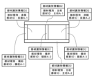
- FIG. 17 is a diagram for explaining member discrimination using the structure model D5 and the information D7 on the imaging plan.
- the information D7 about the imaging plan includes information about the imaging order of the structure OBJ, information indicating the imaging position of the imaging device 50 at the time of imaging, and information indicating the imaging direction of the imaging device 50 at the time of imaging. , contains the member ID.
- the structure image D1 is stored in the storage 18 of the image processing device 10, and the structure image D1 can be sorted according to the imaging order, that is, the shooting date and time.
- the member determination unit 120 uses the imaging target calculation unit 120E to determine the imaging order and the imaging order.
- the structure image D1 sorted based on is associated with the member ID. Thereby, it is possible to specify the member appearing in each structure image D1.
- FIG. 18 is a flow chart showing the member determination process (step S12 in FIG. 3) according to the fifth embodiment of the present invention.
- control unit 12 reads the structure model D5 from the storage 18 or external storage. Also, the control unit 12 reads the information D7 on the imaging plan (step S60).
- the information D7 related to the imaging plan may be stored as attached information of the structure image D1, or may be stored in a separate file associated with the structure image D1.
- the member determination unit 120 determines the members appearing in the structure image D1 from the correspondence relationship between the information D7 regarding the imaging plan of the structure image D1 and the structure model D5 (step S62).
- the member identification unit 120 outputs the member identification result to the identification information provision unit 122 (step S64). Thereby, member identification information can be added to the structure image D1 (step S14 in FIG. 3).
- the member identification information D2 can be added to the structure image D1 by referring to the structure model D5 and the information on the imaging plan. This makes it possible to easily classify and organize the structure images D1.
- the image processing apparatus 10 may add identification information indicating the imaging order to the file of the structure image D1 after imaging, or the imaging apparatus 50 may add identification information immediately after imaging. You may do so.
- FIG. 19 is a block diagram showing image processing functions according to an additional embodiment.
- control unit 12 can realize the functions of the damage information adding unit 124, the added information editing unit 126, and the structure image searching unit 128.
- the damage information addition unit 124 detects damage from the structure image D1 and adds damage information about the damage to the structure image D1.
- the damage information is, for example, information such as the position of the damage (information indicating where the damage is in the structure image D1 (for example, coordinates in the structure image D1)), type, size, or degree (progress). contains.
- the damage information providing unit 124 is created by supervised learning for learning the relationship between input and output data, for example, using teacher data in which damage images are input and damage information is output (for example, classification instrument) can be used. Note that the learning algorithm of the damage information providing unit 124 is not limited to supervised learning, and may be unsupervised learning.
- the damage information may be included in the structure image D1 as attached information (for example, Exif information) of the structure image D1, or may be a separate file associated with the structure image D1.
- the added information editing unit 126 is means for editing added information such as member identification information D2 and damage information to be added to the structure image D1.
- the added information editing unit 126 can edit added information to the structure image D1 before or after the fact.
- the additional information editing unit 126 when editing the additional information in advance, causes the display unit 16 to display the structure image D1 and the additional information before adding the additional information to the structure image D1. Then, the added information editing unit 126 adds added information to the structure image D1 in accordance with the approval of the added information from the input unit 14 or the input of an instruction to edit the added information.
- the added information editing unit 126 causes the display unit 16 to display the structure image D1 to which the added information has already been added and the added information. Then, the added information editing unit 126 edits the added information that has already been added to the structure image D1 according to the instruction input for editing the added information from the input unit 14 .
- the structure image search unit 128 receives an input of a search key from the input unit 14, searches for a structure image D1 corresponding to the search key, and causes the display unit 16 to display the structure image D1.
- the member identification information D2, damage information, or the like can be used as the added information as the search key.
- the image processing apparatus 10 can add at least one function of the damage information adding unit 124, the added information editing unit 126, and the structure image searching unit 128 according to the additional embodiments. .
- an imaging device for capturing an image of a structure may be configured to include the image processing device and the image processing function according to each of the above embodiments.
- FIG. 20 is a block diagram showing an imaging device (image processing device) having an image processing function according to Modification 1. As shown in FIG.
- An imaging device 50A according to Modification 1 is, for example, an unmanned aerial vehicle such as a multicopter or a drone with a camera 54 mounted thereon.
- the imaging device 50A is capable of wireless communication with the controller 70 and performs flight and imaging according to control signals from the controller 70 .
- the imaging device 50A according to Modification 1 includes the image processing functions according to the above embodiments, and is an example of the image processing device according to the present invention.
- an imaging device 50A includes a control unit 52, a camera 54, a driving unit 56, a positioning unit 58, a battery 60, a storage 62, and a communication interface (communication I/F) 64.
- the control unit 52 includes a processor (for example, CPU or GPU) that controls the operation of each unit of the imaging device 50A, and a RAM that is used as a working area for various calculations.
- a processor for example, CPU or GPU
- the processor of the control unit 52 can implement the functions of the member determination unit 520 and the identification information provision unit 522 by reading the image processing program P1 from the storage 62 and executing it.
- the member determining unit 520 and the identification information providing unit 522 are the same as the member determining unit 120 and the identification information providing unit 122 in each of the above-described embodiments, respectively, so description thereof will be omitted.
- the camera (imaging unit) 54 is for capturing the structure image D1 of the structure OBJ to be inspected, and includes, for example, a CCD camera or an infrared camera.
- the driving unit 56 includes a motor for rotating a propulsion device such as the propeller 66 attached to the imaging device 50A, and an ESC (Electric Speed Controller) for controlling the rotation speed of the motor.
- a motor for rotating a propulsion device such as the propeller 66 attached to the imaging device 50A
- an ESC Electric Speed Controller
- the driving unit 56 can obtain lift and propulsive force for flying the imaging device 50A.
- the positioning unit 58 is a device that acquires position information indicating the position and orientation information indicating the orientation of the imaging device 50A.
- the positioning unit 58 includes, for example, a GPS device, an inertial sensor and an altitude sensor.
- the GPS device performs three-dimensional positioning of the position of the imaging device 50A based on signals emitted from GPS satellites, and acquires position information (eg, latitude and longitude).
- the inertial sensor includes, for example, a 3-axis acceleration sensor or a 3-axis gyro sensor, and acquires information (eg, speed information, acceleration information, and attitude information) indicating the flight state of the imaging device 50A.
- the altitude sensor includes, for example, a barometric, GPS, laser, or radar altimeter.
- the GPS position information, the information indicating the flight state, and the information about the altitude are stored in the storage 62 as the information D6 indicating the imaging situation.
- the battery 60 supplies power to each part of the imaging device 50A.
- a primary battery or a secondary battery can be used as the battery 60, and for example, a lithium polymer battery can be used.
- the storage 62 stores various data including a control program and an image processing program P1 for various calculations, and a structure image D1 (for example, a visible light image or an infrared image) obtained by imaging the structure OBJ to be inspected. do.
- the storage 62 also stores information D7 indicating an imaging plan and information D6 indicating an imaging situation.
- a device including flash memory such as eMMC or SSD can be used.
- the communication I/F 64 is means for wireless communication with the controller 70 .
- the method of wireless communication is not particularly limited, but wireless communication in the 2.4 GHz band or 5.7 GHz band can be used for communication with the controller 70 .
- the communication method is not limited to wireless communication, and wired communication can also be used.
- the controller 70 may be a dedicated Proportional Control System (Proportional Control System) transmitter, or a terminal (for example, a tablet terminal) into which a control application is installed.
- Proportional Control System Proportional Control System
- terminal for example, a tablet terminal
- the structure image D1 classified and organized by the imaging device 50A can be downloaded to the user terminal 300 (for example, a personal computer, a general-purpose computer such as a workstation, a tablet terminal, or the like) for viewing.
- the user terminal 300 for example, a personal computer, a general-purpose computer such as a workstation, a tablet terminal, or the like
- inspection work such as various diagnoses using the structure image D1 and report preparation of inspection/diagnosis results.
- the controller 70 and the user terminal 300 can also be used in common.
- Modification 1 by downloading structure images D1 sorted and organized by the imaging device 50A to the user terminal 300, inspection work of the structure OBJ using the structure images D1 can be easily carried out. It becomes possible.
- the member determination unit 520 of the control unit 52 determines the structure image D1 based on the correspondence relationship between the information D7 regarding the imaging plan of the structure image D1 and the structure model D5. Identify the parts shown.
- the control unit 52 determines that the detection result of the imaging position and the imaging direction by the positioning unit 58 has reached the information D7 regarding the imaging plan. After determining that, that is, at the stage where the detection result of the imaging position and the imaging direction by the positioning unit 58 matches the information D7 on the imaging plan, it is preferable to perform control so that the imaging is performed.
- the present invention is not limited to this.
- an arbitrary moving body such as a vehicle or a robot equipped with a camera may be used.
- the controller 70 is not necessary when the operator gets into the moving body and operates it. It is also possible to use a camera that is not mounted on a moving body.
- a server on the cloud (hereinafter referred to as a cloud server) is configured to have the image processing function according to each of the above embodiments, and the structure image D1 captured by the imaging device 50 is transmitted to the cloud.
- a configuration for uploading to a server is also possible.
- FIG. 21 is a block diagram showing a cloud server having an image processing function according to modification 2.
- the cloud server 200 is a server that can be used through a network NW such as the Internet.
- the cloud server 200 can communicate with the imaging device 50 and the user terminal 300 (for example, a personal computer, a general-purpose computer such as a workstation, a tablet terminal, or the like) via wired communication or wireless communication.
- cloud server 200 according to Modification 2 includes the image processing functions according to the above embodiments, and is an example of the image processing apparatus according to the present invention.
- the structure image D1 captured by the imaging device 50 may be uploaded to the cloud server 200 via, for example, the user terminal 300 or other external device. In this case, communication connection between the cloud server 200 and the imaging device 50 becomes unnecessary.
- the processor 202 of the cloud server 200 reads out the image processing program P1 from the storage 204 and executes it, thereby realizing the functions of the member determination unit 220 and the identification information addition unit 222. ing.
- the member determining unit 220 and the identification information providing unit 222 are the same as the member determining unit 120 and the identification information providing unit 122 in each of the above-described embodiments, respectively, so description thereof will be omitted.
- the storage 204 stores control programs and image processing programs P1 for various calculations, and various data including a structure image D1 (for example, a visible light image or an infrared image) obtained by imaging the structure OBJ to be inspected. do.
- the storage 204 also stores information D7 indicating an imaging plan and information D6 indicating an imaging situation.
- a device including a magnetic disk such as an HDD a device including a flash memory such as an eMMC or an SSD, or the like can be used.
- the structure image D1 classified and organized in the cloud server 200 can be downloaded to the user terminal 300 and viewed. As a result, it is possible to perform inspection work such as various diagnoses using the structure image D1 and report preparation of inspection/diagnosis results.
- Modification 2 by downloading the structure images D1 classified and organized in the cloud server 200 to the user terminal 300, the inspection work of the structure OBJ using the structure images D1 can be easily performed. It becomes possible.
- Modification 3 Further, instead of the form of IaaS (Infrastructure as a Service) like Modification 2, it is also possible to provide the image processing function according to each of the above embodiments as the form of SaaS (Software as a Service). .
- the user terminal 300 first acquires the structure image D1 from the imaging device 50 . Then, the user terminal 300 classifies and organizes the structure images D1 using an image processing function for classifying and organizing images provided through the network NW from a cloud server 200 installed by an application service provider (ASP) or the like. I do.
- ASP application service provider
- the structure image D1 may be uploaded to the cloud server 200, or may be processed while being stored in the storage of the user terminal 300.
- the structure image D1 may be uploaded to the cloud server 200, or may be processed while being stored in the storage of the user terminal 300.
- Features may be applicable.
- the structure images D1 are classified and organized using the image processing function provided by the cloud server 200, thereby facilitating the inspection work of the structure OBJ using the structure images D1. becomes possible.
- the imaging device 50 may call the image classification/organization function provided by the cloud server 200 to classify/organize the images in the storage of the imaging device 50 .
- the configuration according to the additional embodiment shown in FIG. 19 can be added to the imaging device 50A and the cloud server 200 according to Modifications 1 to 3.
Landscapes
- Engineering & Computer Science (AREA)
- Theoretical Computer Science (AREA)
- Physics & Mathematics (AREA)
- General Physics & Mathematics (AREA)
- Computer Vision & Pattern Recognition (AREA)
- Multimedia (AREA)
- Databases & Information Systems (AREA)
- Medical Informatics (AREA)
- Artificial Intelligence (AREA)
- Computing Systems (AREA)
- Quality & Reliability (AREA)
- Evolutionary Computation (AREA)
- General Health & Medical Sciences (AREA)
- Health & Medical Sciences (AREA)
- Software Systems (AREA)
- Architecture (AREA)
- Civil Engineering (AREA)
- Structural Engineering (AREA)
- Processing Or Creating Images (AREA)
- Information Retrieval, Db Structures And Fs Structures Therefor (AREA)
- Image Analysis (AREA)
Priority Applications (4)
| Application Number | Priority Date | Filing Date | Title |
|---|---|---|---|
| CN202280062410.1A CN117980967A (zh) | 2021-09-28 | 2022-08-23 | 图像处理装置、方法及程序 |
| JP2023550458A JP7836827B2 (ja) | 2021-09-28 | 2022-08-23 | 画像処理装置、方法及びプログラム |
| EP22875653.2A EP4411069A4 (en) | 2021-09-28 | 2022-08-23 | IMAGE PROCESSING DEVICE, METHOD AND PROGRAM |
| US18/610,984 US20240233380A1 (en) | 2021-09-28 | 2024-03-20 | Image processing apparatus, method, and program |
Applications Claiming Priority (2)
| Application Number | Priority Date | Filing Date | Title |
|---|---|---|---|
| JP2021-158213 | 2021-09-28 | ||
| JP2021158213 | 2021-09-28 |
Related Child Applications (1)
| Application Number | Title | Priority Date | Filing Date |
|---|---|---|---|
| US18/610,984 Continuation US20240233380A1 (en) | 2021-09-28 | 2024-03-20 | Image processing apparatus, method, and program |
Publications (1)
| Publication Number | Publication Date |
|---|---|
| WO2023053781A1 true WO2023053781A1 (ja) | 2023-04-06 |
Family
ID=85782331
Family Applications (1)
| Application Number | Title | Priority Date | Filing Date |
|---|---|---|---|
| PCT/JP2022/031749 Ceased WO2023053781A1 (ja) | 2021-09-28 | 2022-08-23 | 画像処理装置、方法及びプログラム |
Country Status (5)
| Country | Link |
|---|---|
| US (1) | US20240233380A1 (https=) |
| EP (1) | EP4411069A4 (https=) |
| JP (1) | JP7836827B2 (https=) |
| CN (1) | CN117980967A (https=) |
| WO (1) | WO2023053781A1 (https=) |
Citations (6)
| Publication number | Priority date | Publication date | Assignee | Title |
|---|---|---|---|---|
| WO2015163106A1 (ja) | 2014-04-25 | 2015-10-29 | ソニー株式会社 | 制御装置、撮像装置、制御方法、撮像方法及びコンピュータプログラム |
| WO2017119202A1 (ja) * | 2016-01-06 | 2017-07-13 | 富士フイルム株式会社 | 構造物の部材特定装置及び方法 |
| JP2019175015A (ja) * | 2018-03-27 | 2019-10-10 | 株式会社竹中工務店 | 被災情報処理装置、及び被災情報処理モデル学習装置 |
| JP2020035094A (ja) * | 2018-08-28 | 2020-03-05 | オリンパス株式会社 | 機械学習装置、教師用データ作成装置、推論モデル、および教師用データ作成方法 |
| CN112241565A (zh) * | 2020-10-27 | 2021-01-19 | 万翼科技有限公司 | 建模方法及相关装置 |
| JP2021140445A (ja) * | 2020-03-05 | 2021-09-16 | 株式会社トプコン | 情報処理装置、推論モデル構築方法、情報処理方法、推論モデル、プログラム、及び記録媒体 |
Family Cites Families (2)
| Publication number | Priority date | Publication date | Assignee | Title |
|---|---|---|---|---|
| JP2012022551A (ja) * | 2010-07-15 | 2012-02-02 | Hisatomo Takeuchi | 建物3dテクスチャモデル処理電子情報処理装置 |
| CN112489195B (zh) * | 2020-11-26 | 2024-09-20 | 新拓三维技术(深圳)有限公司 | 一种弯管机的快速调机方法及系统 |
-
2022
- 2022-08-23 CN CN202280062410.1A patent/CN117980967A/zh active Pending
- 2022-08-23 JP JP2023550458A patent/JP7836827B2/ja active Active
- 2022-08-23 EP EP22875653.2A patent/EP4411069A4/en active Pending
- 2022-08-23 WO PCT/JP2022/031749 patent/WO2023053781A1/ja not_active Ceased
-
2024
- 2024-03-20 US US18/610,984 patent/US20240233380A1/en active Pending
Patent Citations (6)
| Publication number | Priority date | Publication date | Assignee | Title |
|---|---|---|---|---|
| WO2015163106A1 (ja) | 2014-04-25 | 2015-10-29 | ソニー株式会社 | 制御装置、撮像装置、制御方法、撮像方法及びコンピュータプログラム |
| WO2017119202A1 (ja) * | 2016-01-06 | 2017-07-13 | 富士フイルム株式会社 | 構造物の部材特定装置及び方法 |
| JP2019175015A (ja) * | 2018-03-27 | 2019-10-10 | 株式会社竹中工務店 | 被災情報処理装置、及び被災情報処理モデル学習装置 |
| JP2020035094A (ja) * | 2018-08-28 | 2020-03-05 | オリンパス株式会社 | 機械学習装置、教師用データ作成装置、推論モデル、および教師用データ作成方法 |
| JP2021140445A (ja) * | 2020-03-05 | 2021-09-16 | 株式会社トプコン | 情報処理装置、推論モデル構築方法、情報処理方法、推論モデル、プログラム、及び記録媒体 |
| CN112241565A (zh) * | 2020-10-27 | 2021-01-19 | 万翼科技有限公司 | 建模方法及相关装置 |
Non-Patent Citations (1)
| Title |
|---|
| See also references of EP4411069A4 |
Also Published As
| Publication number | Publication date |
|---|---|
| JPWO2023053781A1 (https=) | 2023-04-06 |
| US20240233380A1 (en) | 2024-07-11 |
| EP4411069A1 (en) | 2024-08-07 |
| JP7836827B2 (ja) | 2026-03-27 |
| CN117980967A (zh) | 2024-05-03 |
| EP4411069A4 (en) | 2024-12-25 |
Similar Documents
| Publication | Publication Date | Title |
|---|---|---|
| JP6833452B2 (ja) | 巡視点検システム、情報処理装置、巡視点検制御プログラム | |
| JP6583840B1 (ja) | 検査システム | |
| Toriumi et al. | UAV-based inspection of bridge and tunnel structures: an application review | |
| JP6404527B1 (ja) | カメラ制御システム、カメラ制御方法、およびプログラム | |
| CN112418096A (zh) | 检测跌的方法、装置和机器人 | |
| JP2019125113A (ja) | 情報処理装置、情報処理方法 | |
| JP2025041720A (ja) | 検査システム | |
| CN120063242A (zh) | 一种机器人语义导航方法、系统、终端及存储介质 | |
| JP2005322002A (ja) | 複合人工知能装置 | |
| JP6943183B2 (ja) | 位置特定装置、位置特定方法、位置特定プログラムおよびカメラ装置 | |
| CN117405832A (zh) | 一种空气质量监测方法、装置、设备及可读存储介质 | |
| JP7836827B2 (ja) | 画像処理装置、方法及びプログラム | |
| JP7471953B2 (ja) | 点検システムおよび点検方法 | |
| JP6681102B2 (ja) | 検査システム | |
| CN119658715A (zh) | 一种基于用户语音的机器人巡查方法及安全巡查机器人 | |
| US20250272917A1 (en) | Space visualization system and space visualization method | |
| JP6976474B1 (ja) | 情報表示装置、情報表示方法及びプログラム | |
| Gupta et al. | Enhancing Road Safety and ITS Efficiency: A Comprehensive Evaluation of Traffic Sign Detection using YOLOv8 | |
| Batra et al. | A Drone Based Image Dataset Generation Methodology for Single Image Super Resolution | |
| CN118758957B (zh) | 一种递进式多无人机巡回桥梁表观病害快速检测方法 | |
| CN119085626B (zh) | 基于驾考科目的矢量地图构建方法及装置、电子设备 | |
| EP4481527B1 (en) | Mobile apparatus, method for determining position, and non-transitory recording medium | |
| US20240054789A1 (en) | Drone data collection optimization for evidence recording | |
| JP2025502282A (ja) | 視覚的測位方法、これを用いる制御サーバー及び建物 | |
| JP2025151429A (ja) | 離隔判定装置、離隔判定システム、離隔判定方法及びプログラム |
Legal Events
| Date | Code | Title | Description |
|---|---|---|---|
| 121 | Ep: the epo has been informed by wipo that ep was designated in this application |
Ref document number: 22875653 Country of ref document: EP Kind code of ref document: A1 |
|
| WWE | Wipo information: entry into national phase |
Ref document number: 202280062410.1 Country of ref document: CN |
|
| WWE | Wipo information: entry into national phase |
Ref document number: 2023550458 Country of ref document: JP |
|
| NENP | Non-entry into the national phase |
Ref country code: DE |
|
| ENP | Entry into the national phase |
Ref document number: 2022875653 Country of ref document: EP Effective date: 20240429 |