WO2023053567A1 - 磁気テープ、磁気テープカートリッジ、サーボパターン記録装置、磁気テープドライブ、磁気テープシステム、検出装置、検査装置、サーボパターン記録方法、磁気テープの製造方法、検出方法、及び検査方法 - Google Patents
磁気テープ、磁気テープカートリッジ、サーボパターン記録装置、磁気テープドライブ、磁気テープシステム、検出装置、検査装置、サーボパターン記録方法、磁気テープの製造方法、検出方法、及び検査方法 Download PDFInfo
- Publication number
- WO2023053567A1 WO2023053567A1 PCT/JP2022/021026 JP2022021026W WO2023053567A1 WO 2023053567 A1 WO2023053567 A1 WO 2023053567A1 JP 2022021026 W JP2022021026 W JP 2022021026W WO 2023053567 A1 WO2023053567 A1 WO 2023053567A1
- Authority
- WO
- WIPO (PCT)
- Prior art keywords
- servo
- linear
- magnetic tape
- region
- straight line
- Prior art date
- Legal status (The legal status is an assumption and is not a legal conclusion. Google has not performed a legal analysis and makes no representation as to the accuracy of the status listed.)
- Ceased
Links
Images


Classifications
-
- G—PHYSICS
- G11—INFORMATION STORAGE
- G11B—INFORMATION STORAGE BASED ON RELATIVE MOVEMENT BETWEEN RECORD CARRIER AND TRANSDUCER
- G11B15/00—Driving, starting or stopping record carriers of filamentary or web form; Driving both such record carriers and heads; Guiding such record carriers or containers therefor; Control thereof; Control of operating function
- G11B15/18—Driving; Starting; Stopping; Arrangements for control or regulation thereof
- G11B15/43—Control or regulation of mechanical tension of record carrier, e.g. tape tension
-
- G—PHYSICS
- G11—INFORMATION STORAGE
- G11B—INFORMATION STORAGE BASED ON RELATIVE MOVEMENT BETWEEN RECORD CARRIER AND TRANSDUCER
- G11B15/00—Driving, starting or stopping record carriers of filamentary or web form; Driving both such record carriers and heads; Guiding such record carriers or containers therefor; Control thereof; Control of operating function
- G11B15/60—Guiding record carrier
- G11B15/602—Guiding record carrier for track selection, acquisition or following
-
- G—PHYSICS
- G11—INFORMATION STORAGE
- G11B—INFORMATION STORAGE BASED ON RELATIVE MOVEMENT BETWEEN RECORD CARRIER AND TRANSDUCER
- G11B15/00—Driving, starting or stopping record carriers of filamentary or web form; Driving both such record carriers and heads; Guiding such record carriers or containers therefor; Control thereof; Control of operating function
- G11B15/60—Guiding record carrier
- G11B15/62—Maintaining desired spacing between record carrier and head
-
- G—PHYSICS
- G11—INFORMATION STORAGE
- G11B—INFORMATION STORAGE BASED ON RELATIVE MOVEMENT BETWEEN RECORD CARRIER AND TRANSDUCER
- G11B20/00—Signal processing not specific to the method of recording or reproducing; Circuits therefor
- G11B20/10—Digital recording or reproducing
- G11B20/18—Error detection or correction; Testing, e.g. of drop-outs
-
- G—PHYSICS
- G11—INFORMATION STORAGE
- G11B—INFORMATION STORAGE BASED ON RELATIVE MOVEMENT BETWEEN RECORD CARRIER AND TRANSDUCER
- G11B21/00—Head arrangements not specific to the method of recording or reproducing
- G11B21/02—Driving or moving of heads
- G11B21/10—Track finding or aligning by moving the head ; Provisions for maintaining alignment of the head relative to the track during transducing operation, i.e. track following
-
- G—PHYSICS
- G11—INFORMATION STORAGE
- G11B—INFORMATION STORAGE BASED ON RELATIVE MOVEMENT BETWEEN RECORD CARRIER AND TRANSDUCER
- G11B23/00—Record carriers not specific to the method of recording or reproducing; Accessories, e.g. containers, specially adapted for co-operation with the recording or reproducing apparatus ; Intermediate mediums; Apparatus or processes specially adapted for their manufacture
- G11B23/02—Containers; Storing means both adapted to cooperate with the recording or reproducing means
- G11B23/04—Magazines; Cassettes for webs or filaments
- G11B23/08—Magazines; Cassettes for webs or filaments for housing webs or filaments having two distinct ends
- G11B23/107—Magazines; Cassettes for webs or filaments for housing webs or filaments having two distinct ends using one reel or core, one end of the record carrier coming out of the magazine or cassette
-
- G—PHYSICS
- G11—INFORMATION STORAGE
- G11B—INFORMATION STORAGE BASED ON RELATIVE MOVEMENT BETWEEN RECORD CARRIER AND TRANSDUCER
- G11B23/00—Record carriers not specific to the method of recording or reproducing; Accessories, e.g. containers, specially adapted for co-operation with the recording or reproducing apparatus ; Intermediate mediums; Apparatus or processes specially adapted for their manufacture
- G11B23/02—Containers; Storing means both adapted to cooperate with the recording or reproducing means
- G11B23/113—Apparatus or processes specially adapted for the manufacture of magazines or cassettes, e.g. initial loading into container
-
- G—PHYSICS
- G11—INFORMATION STORAGE
- G11B—INFORMATION STORAGE BASED ON RELATIVE MOVEMENT BETWEEN RECORD CARRIER AND TRANSDUCER
- G11B33/00—Constructional parts, details or accessories not provided for in the other groups of this subclass
- G11B33/12—Disposition of constructional parts in the apparatus, e.g. of power supply, of modules
-
- G—PHYSICS
- G11—INFORMATION STORAGE
- G11B—INFORMATION STORAGE BASED ON RELATIVE MOVEMENT BETWEEN RECORD CARRIER AND TRANSDUCER
- G11B5/00—Recording by magnetisation or demagnetisation of a record carrier; Reproducing by magnetic means; Record carriers therefor
- G11B5/02—Recording, reproducing, or erasing methods; Read, write or erase circuits therefor
- G11B5/09—Digital recording
-
- G—PHYSICS
- G11—INFORMATION STORAGE
- G11B—INFORMATION STORAGE BASED ON RELATIVE MOVEMENT BETWEEN RECORD CARRIER AND TRANSDUCER
- G11B5/00—Recording by magnetisation or demagnetisation of a record carrier; Reproducing by magnetic means; Record carriers therefor
- G11B5/127—Structure or manufacture of heads, e.g. inductive
- G11B5/265—Structure or manufacture of a head with more than one gap for erasing, recording or reproducing on the same track
-
- G—PHYSICS
- G11—INFORMATION STORAGE
- G11B—INFORMATION STORAGE BASED ON RELATIVE MOVEMENT BETWEEN RECORD CARRIER AND TRANSDUCER
- G11B5/00—Recording by magnetisation or demagnetisation of a record carrier; Reproducing by magnetic means; Record carriers therefor
- G11B5/127—Structure or manufacture of heads, e.g. inductive
- G11B5/29—Structure or manufacture of unitary devices formed of plural heads for more than one track
-
- G—PHYSICS
- G11—INFORMATION STORAGE
- G11B—INFORMATION STORAGE BASED ON RELATIVE MOVEMENT BETWEEN RECORD CARRIER AND TRANSDUCER
- G11B5/00—Recording by magnetisation or demagnetisation of a record carrier; Reproducing by magnetic means; Record carriers therefor
- G11B5/48—Disposition or mounting of heads or head supports relative to record carriers ; arrangements of heads, e.g. for scanning the record carrier to increase the relative speed
- G11B5/58—Disposition or mounting of heads or head supports relative to record carriers ; arrangements of heads, e.g. for scanning the record carrier to increase the relative speed with provision for moving the head for the purpose of maintaining alignment of the head relative to the record carrier during transducing operation, e.g. to compensate for surface irregularities of the latter or for track following
- G11B5/584—Disposition or mounting of heads or head supports relative to record carriers ; arrangements of heads, e.g. for scanning the record carrier to increase the relative speed with provision for moving the head for the purpose of maintaining alignment of the head relative to the record carrier during transducing operation, e.g. to compensate for surface irregularities of the latter or for track following for track following on tapes
- G11B5/588—Disposition or mounting of heads or head supports relative to record carriers ; arrangements of heads, e.g. for scanning the record carrier to increase the relative speed with provision for moving the head for the purpose of maintaining alignment of the head relative to the record carrier during transducing operation, e.g. to compensate for surface irregularities of the latter or for track following for track following on tapes by controlling the position of the rotating heads
- G11B5/592—Disposition or mounting of heads or head supports relative to record carriers ; arrangements of heads, e.g. for scanning the record carrier to increase the relative speed with provision for moving the head for the purpose of maintaining alignment of the head relative to the record carrier during transducing operation, e.g. to compensate for surface irregularities of the latter or for track following for track following on tapes by controlling the position of the rotating heads using bimorph elements supporting the heads
- G11B5/5921—Disposition or mounting of heads or head supports relative to record carriers ; arrangements of heads, e.g. for scanning the record carrier to increase the relative speed with provision for moving the head for the purpose of maintaining alignment of the head relative to the record carrier during transducing operation, e.g. to compensate for surface irregularities of the latter or for track following for track following on tapes by controlling the position of the rotating heads using bimorph elements supporting the heads using auxiliary signals, e.g. pilot signals
- G11B5/5926—Disposition or mounting of heads or head supports relative to record carriers ; arrangements of heads, e.g. for scanning the record carrier to increase the relative speed with provision for moving the head for the purpose of maintaining alignment of the head relative to the record carrier during transducing operation, e.g. to compensate for surface irregularities of the latter or for track following for track following on tapes by controlling the position of the rotating heads using bimorph elements supporting the heads using auxiliary signals, e.g. pilot signals recorded in separate tracks, e.g. servo tracks
- G11B5/5928—Longitudinal tracks
-
- G—PHYSICS
- G11—INFORMATION STORAGE
- G11B—INFORMATION STORAGE BASED ON RELATIVE MOVEMENT BETWEEN RECORD CARRIER AND TRANSDUCER
- G11B5/00—Recording by magnetisation or demagnetisation of a record carrier; Reproducing by magnetic means; Record carriers therefor
- G11B5/74—Record carriers characterised by the form, e.g. sheet shaped to wrap around a drum
- G11B5/78—Tape carriers
-
- G—PHYSICS
- G11—INFORMATION STORAGE
- G11B—INFORMATION STORAGE BASED ON RELATIVE MOVEMENT BETWEEN RECORD CARRIER AND TRANSDUCER
- G11B5/00—Recording by magnetisation or demagnetisation of a record carrier; Reproducing by magnetic means; Record carriers therefor
- G11B5/84—Processes or apparatus specially adapted for manufacturing record carriers
Definitions
- the technology of the present disclosure relates to a magnetic tape, a magnetic tape cartridge, a servo pattern recording device, a magnetic tape drive, a magnetic tape system, a detection device, an inspection device, a servo pattern recording method, a magnetic tape manufacturing method, a detection method, and an inspection method. .
- U.S. Pat. No. 8,094,402 addresses a problem in magnetic tape devices where read and/or write errors occur when the tape is not passing the head with proper tension and/or skew angle. .
- the system described in U.S. Pat. No. 8,094,402 includes a head having an array of at least one of readers and writers, a drive mechanism for passing a magnetic recording tape over the head, coupled to the head.
- a skew-inducing mechanism adapted to adjust the skew angle of the longitudinal axis of the array with respect to a direction perpendicular to the direction in which the tape travels over the head and a controller in communication with the head.
- the system described in U.S. Pat. No. 8,094,402 also determines the tape dimensional stability of the tape and adjusts the skew angle away from the normal to the direction of tape travel so that the tape dimensional stability is in the contracted state. If so, reduce tape tension across the head.
- U.S. Pat. No. 6,781,784 discloses a method in which longitudinally offset read elements are selectively used to read data tracks on a magnetic tape having lateral distortion. ing.
- the read elements are part of the tape head oriented azimuthally with respect to the tape, creating a lateral offset between the read elements. This lateral offset is used to minimize the effects of lateral tape distortion.
- Japanese Unexamined Patent Application Publication No. 2009-123288 discloses that a plurality of magnetic elements each for at least one of reproducing data recorded on a plurality of data tracks provided on a magnetic tape and recording data on each of the data tracks is provided as a first magnetic element.
- head units arranged in parallel on a straight line at equal intervals; a moving mechanism for moving the head units;
- a head device is disclosed that includes a control unit that performs tracking control for tracking.
- the moving mechanism rotates the head portion in a direction to increase or decrease the angle formed by the second straight line and the first straight line along the width of the magnetic tape.
- tracking control is executed, the control unit rotates the head unit with respect to the moving mechanism by an angle increase/decrease amount according to the change in the interval of each data track, and each track is moved to each data track. On-track the magnetic element.
- Japanese Patent Application Laid-Open No. 2000-260014 discloses a method of forming a servo track structure comprising the steps of forming at least one servo track having a width and recording steps of repetitively recording a servo pattern within the servo track. and wherein the recording step includes repeated simultaneous recording of the first and second reference pattern lines and the track pattern lines within the servo track.
- Each of the first and second reference pattern lines has the same predetermined shape and extends across the width of the servo track, and the track pattern line has a predetermined shape different from the predetermined shape of the first and second reference pattern lines. and extends across the width of the servo track.
- Japanese Patent Application Laid-Open No. 2020-140744 discloses an acquisition unit that acquires information about the linearity of a servo pattern recorded on a servo band of a magnetic tape of a magnetic tape cartridge from a magnetic tape cartridge, and a track area included in the magnetic tape.
- a reading element unit in which at least two reading elements each read data from a specific track area including a reading target track by a linear scanning method are arranged in close proximity; a servo reading element for reading a servo pattern; a control unit that controls the positioning of the reading element unit using the read signal of the servo pattern read by the reading element and the linearity information acquired by the acquisition unit; a deriving unit for deriving the amount of positional deviation between the magnetic tape and the reading element unit using the read signal of the servo pattern; and an extraction unit for extracting the data recorded in the track to be read from the reading result by applying a waveform equalization process.
- One embodiment of the technology of the present disclosure provides a magnetic tape, a magnetic tape cartridge, a servo pattern recording device, a magnetic tape drive, a magnetic tape system, a detection device, an inspection device, a servo, which can obtain a highly reliable servo signal.
- a pattern recording method, a magnetic tape manufacturing method, a detection method, and an inspection method are provided.
- a first aspect of the technology of the present disclosure is a magnetic tape on which a plurality of servo patterns are recorded along the longitudinal direction, the servo pattern being at least one linear magnetization region pair,
- the pair is a linearly magnetized first linearly magnetized region and a linearly magnetized second linearly magnetized region, and the first linearly magnetized region and the second linearly magnetized region are formed on the magnetic tape.
- a second aspect of the technology of the present disclosure is the same as the first aspect, in which the positions of both ends of the first linear magnetization region and the positions of both ends of the second linear magnetization region are aligned in the width direction of the magnetic tape. It is the magnetic tape which concerns.
- a third aspect of the technology of the present disclosure is the magnetic tape according to the second aspect, in which the total length of the first linear magnetization region is shorter than the total length of the second linear magnetization region.
- a fourth aspect of the technology of the present disclosure is that the first linear magnetization region is a set of a plurality of first magnetization lines, and the second linear magnetization region is a set of a plurality of second magnetization lines.
- the geometric characteristics of the pair of linear magnetization regions on the magnetic tape are such that the axis of symmetry of the pair of virtual linear regions tilted line-symmetrically with respect to the first virtual straight line is A first aspect corresponding to geometric characteristics based on a pair of virtual linear regions when the whole pair of virtual linear regions is tilted with respect to the first virtual straight line by tilting with respect to the first virtual straight line A magnetic tape according to any one of 4th to 4th aspects.
- the geometric characteristics of the pair of linear magnetization regions on the magnetic tape are such that the symmetry axis of the pair of virtual linear regions that are tilted line-symmetrically with respect to the first virtual straight line is Both ends of one of the pair of virtual linear regions when the whole of the pair of virtual linear regions is tilted with respect to the first virtual straight line by tilting with respect to the first virtual straight line
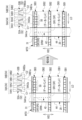
- a plurality of servo bands are formed in the width direction, and servo patterns corresponding between the servo bands are arranged in the longitudinal direction of the magnetic tape between adjacent servo bands in the width direction.
- the servo bands are separated by frames defined based on at least one set of servo patterns, and the frames are longitudinally separated between widthwise adjacent servo bands.
- 8 is a magnetic tape according to the seventh aspect, which is offset by a predetermined interval;
- a ninth aspect of the technology of the present disclosure is that the predetermined interval is an angle formed between frames having a corresponding relationship between servo bands adjacent in the width direction and the first virtual straight line, and between servo bands adjacent in the width direction.
- the magnetic tape according to the eighth aspect which is defined based on the pitch of .
- the predetermined interval is an angle formed by the first imaginary straight line and between frames having no corresponding relationship between servo bands adjacent in the width direction.
- the magnetic tape according to the eighth aspect defined based on the pitch and the total length of the frame in the longitudinal direction.
- each of the first linear magnetization region and the second linear magnetization region is a set of a plurality of magnetization straight lines
- the frame is a set of magnetization lines having different numbers of magnetization straight lines. defined based on a servo pattern, and in one servo pattern, the number of magnetization straight lines included in the first linear magnetization region is the same as the number of magnetization straight lines included in the second linear magnetization region;
- a magnetic tape according to any one of aspects 1 to 10.
- a twelfth aspect of the technology of the present disclosure is a magnetic tape cartridge including the magnetic tape according to any one of the first to eleventh aspects and a case containing the magnetic tape.
- a thirteenth aspect of the technology of the present disclosure is a servo pattern recording apparatus including a pulse signal generator and a servo pattern recording head, wherein the pulse signal generator generates the pulse signal, and the servo pattern recording head has a substrate and a plurality of gap patterns formed on the surface of the substrate, and applies a magnetic field to the magnetic tape from the plurality of gap patterns according to a pulse signal to form a plurality of servo patterns in the width direction of the magnetic tape.
- a plurality of gap patterns are formed on the surface along directions corresponding to the width direction, the gap pattern being at least one linear region pair and one linear region of the linear region pair.
- the first linear region and the second linear region which is the other linear region of the pair of linear regions, are inclined in opposite directions with respect to the second imaginary straight line along the direction corresponding to the width direction on the surface. and wherein the first straight line area has a steeper inclination angle with respect to the second imaginary straight line than the second straight line area.
- a fourteenth aspect of the technology of the present disclosure is the thirteenth aspect, wherein the positions of both ends of the first linear region and the positions of both ends of the second linear region are aligned in a direction corresponding to the width direction of the magnetic tape. It is a servo pattern recording apparatus.
- a fifteenth aspect of the technology of the present disclosure is the servo pattern recording apparatus according to the fourteenth aspect, in which the total length of the first linear region is shorter than the total length of the second linear region.
- the geometric characteristics on the surface of the pair of straight line regions are set such that the axis of symmetry of the pair of virtual straight regions that are symmetrically inclined with respect to the second virtual straight line is the second virtual straight line.
- the geometric characteristics on the surface of the pair of straight line regions are set so that the axis of symmetry of the pair of virtual straight regions that are symmetrically inclined with respect to the second virtual straight line is the second virtual straight line.
- the positions of both ends of one of the pair of virtual straight regions when the entire pair of virtual straight regions are tilted with respect to the second virtual straight line by inclining against and the other virtual straight region of the 14th aspect, the 15th aspect, and the 16th aspect that quotes the 14th aspect or the 15th aspect A servo pattern recording apparatus according to any one aspect.
- the plurality of gap patterns are shifted at a predetermined interval in the direction corresponding to the longitudinal direction of the magnetic tape between adjacent gap patterns along the direction corresponding to the width direction. and a servo pattern recording apparatus according to any one of the thirteenth to seventeenth aspects.
- a plurality of servo bands are formed along the width direction of the magnetic tape, and the servo bands are frames defined based on at least one set of servo patterns.
- the predetermined interval is defined based on the angle formed between the second imaginary straight line and the frames having a corresponding relationship between the servo bands adjacent in the width direction, and the pitch between the servo bands adjacent in the width direction.
- a plurality of servo bands are formed on the magnetic tape along the width direction, and the servo bands are frames defined based on at least one set of servo patterns.
- the angle formed by the second imaginary straight line and the second imaginary straight line, the pitch between the servo bands adjacent in the width direction, and the longitudinal direction of the frame The servo pattern recording apparatus according to the eighteenth aspect, defined based on the total length of the .
- a twenty-first aspect of the technology of the present disclosure is the servo pattern recording according to any one of the thirteenth to twentieth aspects, wherein the pulse signals used between the plurality of gap patterns are in-phase signals. It is a device.
- a twenty-second aspect of the technology of the present disclosure is a traveling mechanism that causes the magnetic tape according to any one of the first to eleventh aspects to travel along a predetermined route, and a traveling mechanism that causes the magnetic tape to travel.
- a magnetic head having a plurality of servo reading elements for reading a servo pattern on a predetermined path in a state where the servo reading elements are arranged along the longitudinal direction of the magnetic head;
- a magnetic tape drive in which a magnetic head is arranged in a posture in which a third imaginary straight line extending along the longitudinal direction of the magnetic head is inclined with respect to the running direction of the magnetic tape.
- a twenty-third aspect of the technology of the present disclosure is the magnetic tape according to any one aspect of the first to eleventh aspects, and the magnetic tape on the predetermined route while running along the predetermined route.
- a magnetic tape drive mounted with a magnetic head having a plurality of servo reading elements for reading servo patterns, wherein the plurality of servo reading elements are arranged along the longitudinal direction of the magnetic head.
- a magnetic tape system in which a magnetic head is arranged in a posture in which a fourth imaginary straight line extending along the longitudinal direction of the magnetic head is inclined with respect to the running direction of the magnetic tape.
- a twenty-fourth aspect of the technology of the present disclosure is a detection device comprising a processor, wherein the processor reads a servo pattern from the magnetic tape by the servo reading element according to any one of the first to eleventh aspects.
- a detection device that detects a servo signal, which is the result of reading, using an autocorrelation coefficient.
- a pulse signal is generated, and a servo pattern recording head having a substrate and a plurality of gap patterns formed on the surface of the substrate performs magnetic recording from the plurality of gap patterns according to the pulse signal.
- the gap pattern is at least one linear region pair, and a first linear region that is one linear region of the linear region pair and a second linear region that is the other linear region of the linear region pair are formed on the surface It is inclined in opposite directions with respect to the second imaginary straight line along the direction corresponding to the width direction above, and the first straight area has a steeper inclination angle with respect to the second imaginary straight line than the second straight area.
- a twenty-sixth aspect of the technology of the present disclosure is the twenty-fifth aspect, wherein the positions of both ends of the first linear region and the positions of both ends of the second linear region are aligned in a direction corresponding to the width direction of the magnetic tape. This is the servo pattern recording method.
- a twenty-seventh aspect of the technology of the present disclosure is a magnetic tape on which a plurality of servo patterns are recorded by the servo pattern recording apparatus according to any one of the thirteenth to twenty-first aspects.
- a twenty-eighth aspect of the technology of the present disclosure is a magnetic tape cartridge including the magnetic tape according to the twenty-seventh aspect and a case accommodating the magnetic tape.
- a twenty-ninth aspect of the technology of the present disclosure includes a running mechanism for running the magnetic tape according to the twenty-seventh aspect along a predetermined route, and a servo pattern on the predetermined route while the magnetic tape is run by the running mechanism.
- a magnetic head having a plurality of servo reading elements for reading, wherein the plurality of servo reading elements are arranged along the longitudinal direction of the magnetic head, and the magnetic head is arranged along the longitudinal direction of the magnetic head;
- the magnetic tape drive is arranged in a posture in which the fifth imaginary straight line along the is inclined with respect to the running direction of the magnetic tape.
- a thirtieth aspect of the technology of the present disclosure includes the magnetic tape according to the twenty-seventh aspect, and a plurality of servo reading elements that read a servo pattern on a predetermined path while the magnetic tape is running along the predetermined path.
- a magnetic tape drive mounted with a magnetic head, wherein a plurality of servo reading elements are arranged along the longitudinal direction of the magnetic head, and the magnetic head is arranged along the longitudinal direction of the magnetic head
- the magnetic tape system is arranged in a posture in which the sixth imaginary straight line along the magnetic tape is inclined with respect to the running direction of the magnetic tape.
- a thirty-first aspect of the technology of the present disclosure is a detection device comprising a processor, wherein the processor generates a servo signal, which is a result of reading a servo pattern from the magnetic tape by a servo reading element according to the twenty-seventh aspect, It is a detection device that detects using an autocorrelation coefficient.
- a thirty-second aspect of the technology of the present disclosure is a servo pattern recording step of recording a plurality of servo patterns on a magnetic tape according to the servo pattern recording method according to the twenty-fifth aspect or the twenty-sixth aspect; and a removing step.
- a thirty-third aspect of the technology of the present disclosure is a detection device according to the twenty-fourth aspect or the thirty-first aspect, and a servo band in which a servo pattern is recorded on a magnetic tape based on a servo signal detected by the detection device. and an inspection processor for inspecting.
- a thirty-fourth aspect of the technology of the present disclosure is a result of reading a servo pattern by a servo reading element from the magnetic tape according to any one of the first to eleventh aspects and the twenty-seventh aspect.
- a detection method including detecting a servo signal using an autocorrelation coefficient.
- a thirty-fifth aspect of the technology of the present disclosure is an inspection method including inspecting a servo band in which a servo pattern is recorded on a magnetic tape, based on the servo signal detected by the detection method according to the thirty-fourth aspect. is.
- FIG. 1 is a block diagram showing an example of the configuration of a magnetic tape system according to an embodiment
- FIG. 1 is a schematic perspective view showing an example of the appearance of a magnetic tape cartridge according to an embodiment
- FIG. 1 is a schematic configuration diagram showing an example of a hardware configuration of a magnetic tape drive according to an embodiment
- FIG. 1 is a schematic perspective view showing an example of a mode in which a magnetic field is emitted from the lower side of a magnetic tape cartridge according to an embodiment by a non-contact reading/writing device
- FIG. 1 is a schematic configuration diagram showing an example of a hardware configuration of a magnetic tape drive according to an embodiment
- FIG. 1 is a conceptual diagram showing an example of a state in which a magnetic head is arranged on a conventionally known magnetic tape, observed from the surface side of the magnetic tape
- FIG. FIG. 2 is a conceptual diagram showing an example of a state in which a magnetic tape before and after the width of a conventionally known magnetic tape shrinks is observed from the surface side of the magnetic tape.
- FIG. 2 is a conceptual diagram showing an example of a state in which a magnetic head is skewed on a conventionally known magnetic tape, observed from the surface side of the magnetic tape
- 1 is a conceptual diagram showing an example of a magnetic tape according to an embodiment observed from the surface side of the magnetic tape;
- FIG. 4 is a conceptual diagram showing an example of the relationship between the geometrical characteristics of an actual servo pattern and the geometrical characteristics of a virtual servo pattern
- FIG. 2 is a conceptual diagram showing an example of a state observed from the surface side of a magnetic tape in which frames corresponding to adjacent servo bands in the width direction of the magnetic tape according to the embodiment are shifted at predetermined intervals.
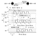
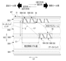
- FIG. 2 is a conceptual diagram showing an example of a state in which a servo pattern is read by a servo reading element included in a magnetic head that is not skewed on a magnetic tape, observed from the surface side of the magnetic tape according to the embodiment;
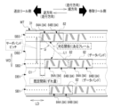
- FIG. 2 is a conceptual diagram showing an example of a state in which a servo pattern is read by a servo reading element included in a magnetic head that is skewed on a magnetic tape according to the embodiment, observed from the surface side of the magnetic tape.
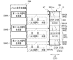
- 3 is a conceptual diagram showing an example of functions of a control device included in the magnetic tape drive according to the embodiment;
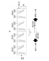
- FIG. FIG. 2 is a conceptual diagram showing an example of processing contents of a position detection section and a control section included in a control device included in the magnetic tape drive according to the embodiment;
- 1 is a conceptual diagram showing an example of a configuration of a servo writer according to an embodiment;
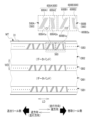
- FIG. 4 is a conceptual diagram showing an example of a mode observed from the front side of the tape (that is, the rear side of the servo pattern recording head).
- FIG. 2 is a conceptual diagram showing an example of a state in which a servo pattern recording head included in a servo writer according to an embodiment is arranged on a magnetic tape, observed from the surface side of the magnetic tape (that is, the back side of the servo pattern recording head); is.
- FIG. 10 is a conceptual diagram showing a first modified example, and is a conceptual diagram showing a modified example of the magnetic tape according to the embodiment (a conceptual diagram showing an example of a state in which the magnetic tape is observed from the surface side of the magnetic tape).
- FIG. 10 is a conceptual diagram showing a first modified example, and is a conceptual diagram showing an example of a mode of servo patterns included in a magnetic tape;
- FIG. 10 is a conceptual diagram showing a mode of servo patterns included in a magnetic tape;
- FIG. 10 is a conceptual diagram showing a first modified example, and a conceptual diagram showing a modified example of the servo pattern recording head included in the servo writer according to the embodiment (a state in which the servo pattern recording head is arranged on the magnetic tape;
- FIG. 4 is a conceptual diagram showing an example of a mode observed from the surface side (that is, the back side of the servo pattern recording head).
- FIG. 11 is a conceptual diagram showing a second modified example, and is a conceptual diagram showing a modified example of the magnetic tape according to the embodiment (a conceptual diagram showing an example of a state in which the magnetic tape is observed from the surface side of the magnetic tape).
- FIG. 11 is a conceptual diagram showing a second modified example, and is a conceptual diagram showing a modified example of the magnetic tape according to the embodiment (a conceptual diagram showing an example of a state in which the magnetic tape is observed from the surface side of the magnetic tape).
- FIG. 11 is a conceptual diagram showing a second modified example, and is a conceptual diagram showing an example of a mode of servo patterns included in a magnetic tape
- FIG. 10 is a conceptual diagram showing a second modified example, and is a conceptual diagram showing a modified example of the servo pattern recording head included in the servo writer according to the embodiment (a state in which the servo pattern recording head is arranged on the magnetic tape
- FIG. 4 is a conceptual diagram showing an example of a mode observed from the surface side (that is, the back side of the servo pattern recording head).
- FIG. 11 is a conceptual diagram showing a third modification, showing a state in which corresponding frames of servo bands adjacent to each other in the width direction of the magnetic tape according to the embodiment are displaced at predetermined intervals, observed from the surface side of the magnetic tape; It is a conceptual diagram which shows an example.
- FIG. 11 is a conceptual diagram showing a fourth modified example, and is a conceptual diagram showing a modified example of the magnetic tape according to the embodiment (a conceptual diagram showing an example of a mode in which the magnetic tape is observed from the surface side of the magnetic tape).
- FIG. 20 is a conceptual diagram showing a fourth modified example, and is a conceptual diagram showing an example of the relationship between the geometrical characteristics of an actual servo pattern and the geometrical characteristics of a virtual servo pattern; FIG.
- FIG. 11 is a conceptual diagram showing a fourth modification, showing an example of a mode observed from the surface side of the magnetic tape in which the corresponding frames of the servo bands adjacent in the width direction of the magnetic tape are shifted at predetermined intervals; It is a diagram.
- FIG. 11 is a conceptual diagram showing a fourth modification, showing an example of a mode in which a state in which a servo pattern is read by a servo reading element included in a magnetic head skewed on a magnetic tape is observed from the surface side of the magnetic tape; is.
- FIG. 11 is a conceptual diagram showing a fourth modification, showing an example of the relationship between a pulse signal generator included in a servo writer and a servo pattern recording head, and a servo pattern recording head included in the servo writer according to the embodiment; 1 is a conceptual diagram showing an example of a mode in which a magnetic tape is arranged in a state observed from the surface side of the magnetic tape (that is, the back side of the servo pattern recording head).
- FIG. 11 is a conceptual diagram showing a fourth modification, in which a state in which a servo pattern recording head included in a servo writer is arranged on a magnetic tape is observed from the surface side of the magnetic tape (that is, the back side of the servo pattern recording head).
- FIG. 11 is a conceptual diagram showing a fourth modification, showing an example of the relationship between a pulse signal generator included in a servo writer and a servo pattern recording head, and a servo pattern recording head included in the servo writer according to the
- FIG. 10 is a conceptual diagram showing an example of a mode in which;
- FIG. 11 is a conceptual diagram showing a fourth modified example, and is a conceptual diagram showing an example of the relationship between the geometrical characteristics of an actual gap pattern and the geometrical characteristics of a virtual gap pattern;
- FIG. 11 is a conceptual diagram showing a fifth modified example, and is a conceptual diagram showing a modified example of the magnetic tape according to the embodiment (a conceptual diagram showing an example of a state in which the magnetic tape is observed from the surface side of the magnetic tape).
- FIG. 20 is a conceptual diagram showing a fifth modified example, and is a conceptual diagram showing an example of a mode of servo patterns included in a magnetic tape;
- FIG. 15 is a conceptual diagram showing a fifth modification, and is a conceptual diagram showing a modification of the servo pattern recording head included in the servo writer according to the embodiment (a state in which the servo pattern recording head is arranged on the magnetic tape is shown in FIG.
- FIG. 4 is a conceptual diagram showing an example of a mode observed from the surface side (that is, the back side of the servo pattern recording head).
- FIG. 11 is a conceptual diagram showing a sixth modified example, and is a conceptual diagram showing a modified example of the magnetic tape according to the embodiment (a conceptual diagram showing an example of a mode in which the magnetic tape is observed from the surface side of the magnetic tape).
- FIG. 4 is a conceptual diagram showing an example of a mode observed from the surface side (that is, the back side of the servo pattern recording head).
- FIG. 11 is a conceptual diagram showing a sixth modified example, and is a conceptual diagram showing a modified example of the magnetic tape according to the embodiment (a conceptual diagram showing an example of a mode in
- FIG. 20 is a conceptual diagram showing a sixth modified example, and is a conceptual diagram showing an example of a mode of a servo pattern included in a magnetic tape
- FIG. 11 is a conceptual diagram showing a sixth modification, and is a conceptual diagram showing a modification of the servo pattern recording head included in the servo writer according to the embodiment (a state in which the servo pattern recording head is arranged on the magnetic tape
- FIG. 4 is a conceptual diagram showing an example of a mode observed from the surface side (that is, the back side of the servo pattern recording head).
- FIG. 14 is a conceptual diagram showing a seventh modification, which is a conceptual diagram showing a modification of the servo pattern recording head included in the servo writer according to the embodiment (a state in which the servo pattern recording head is skewed on the magnetic tape;
- FIG. 4 is a conceptual diagram showing an example of a mode observed from the surface side (that is, the back side of the servo pattern recording head).
- FIG. 20 is a conceptual diagram showing an eighth modification, which is a conceptual diagram showing a modification of the servo pattern recording head included in the servo writer according to the embodiment (a state in which the servo pattern recording head is skewed on the magnetic tape;
- FIG. 20 is a conceptual diagram showing an eighth modification, which is a conceptual diagram showing a modification of the servo pattern recording head included in the servo writer according to the embodiment (a state in which the servo pattern recording head is skewed on the magnetic tape;
- FIG. 14 is a conceptual diagram showing a seventh modification, which is
- FIG. 4 is a conceptual diagram showing an example of a mode observed from the surface side (that is, the back side of the servo pattern recording head).
- FIG. 20 is a conceptual diagram showing a ninth modification, which is a conceptual diagram showing a modification of the servo pattern recording head included in the servo writer according to the embodiment (a state in which the servo pattern recording head is skewed on the magnetic tape;
- FIG. 4 is a conceptual diagram showing an example of a mode observed from the surface side (that is, the back side of the servo pattern recording head).
- FIG. 10 is a conceptual diagram showing a tenth modification, showing an example of the relationship between a pulse signal generator included in a servo writer and a servo pattern recording head, in which the servo pattern recording head included in the servo writer is arranged on a magnetic tape;
- FIG. 3 is a conceptual diagram showing an example of a state observed from the surface side of the magnetic tape (that is, the back side of the servo pattern recording head).
- FIG. 10 is a conceptual diagram showing a tenth modification, in which a state in which a servo pattern recording head included in a servo writer is arranged on a magnetic tape is observed from the surface side of the magnetic tape (that is, the back side of the servo pattern recording head);
- FIG. 10 is a conceptual diagram showing a tenth modification, showing an example of the relationship between a pulse signal generator included in a servo writer and a servo pattern recording head, in which the servo pattern recording head included in the servo writer is
- FIG. 10 is a conceptual diagram showing an example of a mode in which;
- FIG. 11 is a conceptual diagram showing an eleventh modification, in which a state in which a servo pattern recording head included in a servo writer is arranged on a magnetic tape is observed from the surface side of the magnetic tape (that is, the back side of the servo pattern recording head);
- FIG. 10 is a conceptual diagram showing an example of a mode in which;
- FIG. 12 is a conceptual diagram showing a twelfth modification, in which a state in which a servo pattern recording head included in a servo writer is arranged on a magnetic tape is observed from the surface side of the magnetic tape (that is, the back side of the servo pattern recording head);
- FIG. 11 is a conceptual diagram showing an eleventh modification, in which a state in which a servo pattern recording head included in a servo writer is arranged on a magnetic tape is observed from the surface side of the magnetic tape (that is, the back side of the
- FIG. 10 is a conceptual diagram showing an example of a mode in which;
- FIG. 20 is a conceptual diagram showing a thirteenth modified example, and is a conceptual diagram showing a modified example of the magnetic tape according to the embodiment (a conceptual diagram showing an example of a state in which the magnetic tape is observed from the surface side of the magnetic tape).
- Magnetic tapes, magnetic tape cartridges, servo pattern recording devices, magnetic tape drives, magnetic tape systems, detection devices, inspection devices, servo pattern recording methods, magnetic tape manufacturing methods, and detection methods according to the technology of the present disclosure will be described below with reference to the accompanying drawings. , and an example of an embodiment of an inspection method.
- NVM is an abbreviation for "Non-volatile memory”.
- CPU is an abbreviation for "Central Processing Unit”.
- RAM is an abbreviation for "Random Access Memory”.
- EEPROM is an abbreviation for "Electrically Erasable and Programmable Read Only Memory”.
- SSD is an abbreviation for "Solid State Drive”.
- HDD is an abbreviation for "Hard Disk Drive”.
- ASIC is an abbreviation for "Application Specific Integrated Circuit”.
- FPGA is an abbreviation for "Field-Programmable Gate Array”.
- PLC is an abbreviation for "Programmable Logic Controller”.
- IC is an abbreviation for "Integrated Circuit”.
- RFID is an abbreviation for "Radio Frequency Identifier”.
- BOT is an abbreviation for "Beginning Of Tape”.
- EOT is an abbreviation for "End Of Tape”.
- UI is an abbreviation for "User Interface”.
- WAN is an abbreviation for "Wide Area Network”.
- LAN is an abbreviation for "Local Area Network”.
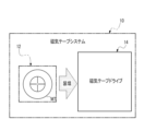
- a magnetic tape system 10 includes a magnetic tape cartridge 12 and a magnetic tape drive 14 .
- the magnetic tape cartridge 12 is loaded into the magnetic tape drive 14 .
- the magnetic tape cartridge 12 accommodates the magnetic tape MT.
- the magnetic tape drive 14 pulls out the magnetic tape MT from the loaded magnetic tape cartridge 12, and while running the pulled out magnetic tape MT, records data on the magnetic tape MT and reads data from the magnetic tape MT. do.
- the magnetic tape MT is an example of the "magnetic tape” according to the technology of the present disclosure.
- the magnetic tape system 10 is an example of a “magnetic tape system” according to the technology of the present disclosure.
- the magnetic tape drive 14 is an example of a “magnetic tape drive” and a “detection device” according to the technology of the present disclosure.
- the magnetic tape cartridge 12 is an example of a “magnetic tape cartridge” according to the technology of the present disclosure.
- FIG. 2 to 4 the direction of loading the magnetic tape cartridge 12 into the magnetic tape drive 14 is indicated by arrow A, and the direction of arrow A is the front direction of the magnetic tape cartridge 12.
- the front side of the magnetic tape cartridge 12 is defined as the front side of the magnetic tape cartridge 12 .
- "front” refers to the front side of the magnetic tape cartridge 12.
- the direction of arrow B perpendicular to the direction of arrow A is defined as the right direction
- the right side of the magnetic tape cartridge 12 is the right side of the magnetic tape cartridge 12.
- "right” refers to the right side of the magnetic tape cartridge 12 .
- FIGS. The upward side of the cartridge 12 is defined as the upper side of the magnetic tape cartridge 12 .
- “upper” refers to the upper side of the magnetic tape cartridge 12.
- the direction opposite to the front direction of the magnetic tape cartridge 12 is defined as the rear direction of the magnetic tape cartridge 12, and the rear direction side of the magnetic tape cartridge 12 is the magnetic tape cartridge 12. It is the rear side of the tape cartridge 12 .
- “rear” refers to the rear side of the magnetic tape cartridge 12.
- the downward direction of the magnetic tape cartridge 12 is defined as the downward direction of the magnetic tape cartridge 12, and the downward direction of the magnetic tape cartridge 12 is the magnetic field. It is the lower side of the tape cartridge 12 .
- “bottom” refers to the underside of the magnetic tape cartridge 12. As shown in FIG.
- the magnetic tape cartridge 12 is generally rectangular in plan view and includes a box-shaped case 16 .
- Case 16 is an example of a "case” according to the technology of the present disclosure.
- the case 16 accommodates the magnetic tape MT.
- the case 16 is made of resin such as polycarbonate, and includes an upper case 18 and a lower case 20 .
- the upper case 18 and the lower case 20 are joined by welding (for example, ultrasonic welding) and screwing with the lower peripheral surface of the upper case 18 and the upper peripheral surface of the lower case 20 being in contact with each other.
- the joining method is not limited to welding and screwing, and other joining methods may be used.
- a delivery reel 22 is rotatably accommodated inside the case 16 .
- the delivery reel 22 has a reel hub 22A, an upper flange 22B1 and a lower flange 22B2.
- the reel hub 22A is formed in a cylindrical shape.
- the reel hub 22 ⁇ /b>A is the axial center of the delivery reel 22 , the axial direction of which extends along the vertical direction of the case 16 , and the reel hub 22 ⁇ /b>A is arranged in the center of the case 16 .
- Each of the upper flange 22B1 and the lower flange 22B2 is formed in an annular shape.
- a center portion of an upper flange 22B1 in plan view is fixed to the upper end portion of the reel hub 22A, and a center portion of a lower flange 22B2 in plan view is fixed to the lower end portion of the reel hub 22A.
- the reel hub 22A and the lower flange 22B2 may be integrally molded.
- a magnetic tape MT is wound around the outer peripheral surface of the reel hub 22A, and the widthwise ends of the magnetic tape MT are held by an upper flange 22B1 and a lower flange 22B2.
- An opening 16B is formed on the front side of the right wall 16A of the case 16.
- the magnetic tape MT is pulled out from the opening 16B.
- a cartridge memory 24 is provided in the lower case 20 . Specifically, a cartridge memory 24 is housed in the right rear end portion of the lower case 20 .
- the cartridge memory 24 is mounted with an IC chip having NVM.
- a so-called passive RFID tag is employed as the cartridge memory 24, and various information is read and written to the cartridge memory 24 without contact.
- Management information for managing the magnetic tape cartridge 12 is stored in the cartridge memory 24 .
- the management information includes, for example, information about the cartridge memory 24 (for example, information that can identify the magnetic tape cartridge 12), information about the magnetic tape MT (for example, information indicating the recording capacity of the magnetic tape MT, and information recorded on the magnetic tape MT). information indicating the outline of the data recorded on the magnetic tape MT, information indicating the items of data recorded on the magnetic tape MT, information indicating the recording format of the data recorded on the magnetic tape MT, etc.), and information on the magnetic tape drive 14 ( For example, it includes information indicating specifications of the magnetic tape drive 14 and signals used by the magnetic tape drive 14).
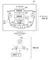
- the magnetic tape drive 14 includes a transport device 26, a magnetic head 28, a control device 30, a storage 32, a UI system device 34, and a communication interface 35.
- the magnetic tape cartridge 12 is loaded along the arrow A direction into the magnetic tape drive 14 .
- the magnetic tape MT is pulled out from the magnetic tape cartridge 12 and used.
- the magnetic tape MT has a magnetic layer 29A, a base film 29B, and a back coat layer 29C.
- the magnetic layer 29A is formed on one side of the base film 29B, and the back coat layer 29C is formed on the other side of the base film 29B.
- Data is recorded on the magnetic layer 29A.
- the magnetic layer 29A contains ferromagnetic powder.
- ferromagnetic powder for example, ferromagnetic powder generally used in the magnetic layers of various magnetic recording media is used.
- a preferred specific example of the ferromagnetic powder is hexagonal ferrite powder. Examples of hexagonal ferrite powder include hexagonal strontium ferrite powder and hexagonal barium ferrite powder.
- the back coat layer 29C is, for example, a layer containing non-magnetic powder such as carbon black.
- the base film 29B is also called a support, and is made of, for example, polyethylene terephthalate, polyethylene naphthalate, polyamide, or the like.
- a non-magnetic layer may be formed between the base film 29B and the magnetic layer 29A.
- the surface on which the magnetic layer 29A is formed is the surface 31 of the magnetic tape MT
- the surface on which the back coat layer 29C is formed is the back surface 33 of the magnetic tape MT.
- the magnetic tape drive 14 uses the magnetic head 28 to magnetically process the surface 31 of the magnetic tape MT.
- magnetic processing refers to recording data on the surface 31 of the magnetic tape MT and reading data from the surface 31 of the magnetic tape MT (that is, reproducing data).
- the magnetic tape drive 14 uses the magnetic head 28 to selectively record data on the surface 31 of the magnetic tape MT and read data from the surface 31 of the magnetic tape MT. That is, the magnetic tape drive 14 pulls out the magnetic tape MT from the magnetic tape cartridge 12, records data on the surface 31 of the pulled out magnetic tape MT using the magnetic head 28, or records data on the surface 31 of the pulled out magnetic tape MT. Data is read using the magnetic head 28 from the .
- the control device 30 controls the magnetic tape drive 14 as a whole.
- the control device 30 is realized by ASIC, but the technology of the present disclosure is not limited to this.
- the control device 30 may be realized by FPGA and/or PLC.
- the control device 30 may be implemented by a computer including a CPU, flash memory (eg, EEPROM and/or SSD, etc.), and RAM.
- it may be realized by combining two or more of ASIC, FPGA, PLC, and computer. That is, the control device 30 may be realized by a combination of hardware configuration and software configuration.
- the control device 30 is an example of a “processor” according to the technology of the present disclosure.
- the storage 32 is connected to the control device 30 , and the control device 30 writes various types of information to the storage 32 and reads various types of information from the storage 32 .
- An example of the storage 32 is flash memory and/or HDD.
- the flash memory and HDD are merely examples, and any non-volatile memory that can be mounted on the magnetic tape drive 14 may be used.
- the UI system device 34 is a device that has a reception function that receives an instruction signal indicating an instruction from the user and a presentation function that presents information to the user.
- the reception function is implemented by, for example, a touch panel, hard keys (for example, keyboard), and/or mouse.
- a presentation function is realized by, for example, a display, a printer, and/or a speaker.
- the UI system device 34 is connected to the control device 30 .
- the control device 30 acquires an instruction signal received by the UI system device 34 .
- the UI system device 34 presents various information to the user under the control of the control device 30 .
- the communication interface 35 is connected to the control device 30 .
- the communication interface 35 is connected to an external device 37 via a communication network (not shown) such as WAN and/or LAN.
- the communication interface 35 communicates various information between the control device 30 and the external device 37 (for example, data for recording on the magnetic tape MT, data read from the magnetic tape MT, and/or instructions given to the control device 30). signals, etc.).
- the external device 37 may be, for example, a personal computer or a mainframe.
- the conveying device 26 is a device that selectively conveys the magnetic tape MT in forward and reverse directions along a predetermined path, and includes a delivery motor 36, a take-up reel 38, a take-up motor 40, and a plurality of guide rollers GR. I have it.
- the forward direction refers to the feeding direction of the magnetic tape MT
- the reverse direction refers to the rewinding direction of the magnetic tape MT.
- the conveying device 26 is an example of a "running mechanism" according to the technology of the present disclosure.
- the delivery motor 36 rotates the delivery reel 22 in the magnetic tape cartridge 12 under the control of the control device 30 .
- the control device 30 controls the rotation direction, rotation speed, rotation torque, and the like of the delivery reel 22 by controlling the delivery motor 36 .
- the winding motor 40 rotates the winding reel 38 under the control of the control device 30 .
- the control device 30 controls the rotation direction, rotation speed, rotation torque, and the like of the take-up reel 38 by controlling the take-up motor 40 .
- the control device 30 rotates the delivery motor 36 and the take-up motor 40 so that the magnetic tape MT travels forward along the predetermined route.
- the rotational speed, rotational torque, etc. of the delivery motor 36 and the take-up motor 40 are adjusted according to the speed at which the magnetic tape MT is wound onto the take-up reel 38 .
- tension is applied to the magnetic tape MT by adjusting the rotational speed and rotational torque of each of the feed motor 36 and the winding motor 40 by the control device 30 .
- the tension applied to the magnetic tape MT is controlled by adjusting the rotational speed and rotational torque of each of the feed motor 36 and the winding motor 40 by the control device 30 .
- the control device 30 When rewinding the magnetic tape MT onto the delivery reel 22, the control device 30 rotates the delivery motor 36 and the take-up motor 40 so that the magnetic tape MT travels in the opposite direction along the predetermined route.
- the tension applied to the magnetic tape MT is controlled by controlling the rotational speed and rotational torque of the delivery motor 36 and the winding motor 40, but the technique of the present disclosure is not limited to this.
- the tension applied to the magnetic tape MT may be controlled using a dancer roller or by drawing the magnetic tape MT into a vacuum chamber.
- Each of the plurality of guide rollers GR is a roller that guides the magnetic tape MT.
- the predetermined path that is, the travel path of the magnetic tape MT, is determined by arranging a plurality of guide rollers GR at positions straddling the magnetic head 28 between the magnetic tape cartridge 12 and the take-up reel 38. .
- the magnetic head 28 has a magnetic element unit 42 and a holder 44 .
- the magnetic element unit 42 is held by a holder 44 so as to come into contact with the running magnetic tape MT.
- the magnetic element unit 42 has a plurality of magnetic elements.
- the magnetic element unit 42 records data on the magnetic tape MT transported by the transport device 26 and reads data from the magnetic tape MT transported by the transport device 26 .
- data refers to, for example, the servo pattern 58 (see FIG. 9) and data other than the servo pattern 58, that is, data recorded in the data band DB (see FIG. 9).
- the magnetic tape drive 14 has a non-contact read/write device 46 .
- the non-contact type read/write device 46 is arranged so as to face the rear surface 24A of the cartridge memory 24 under the magnetic tape cartridge 12 loaded with the magnetic tape cartridge 12, and is non-contact with respect to the cartridge memory 24. Reads and writes information by contact.
- the non-contact read/write device 46 emits a magnetic field MF from the underside of the magnetic tape cartridge 12 toward the cartridge memory 24. As shown in FIG. A magnetic field MF penetrates the cartridge memory 24 .
- the non-contact reading/writing device 46 is connected to the control device 30 . Controller 30 outputs control signals to non-contact read/write device 46 .
- a control signal is a signal for controlling the cartridge memory 24 .
- the non-contact read/write device 46 generates a magnetic field MF according to a control signal input from the control device 30 and emits the generated magnetic field MF toward the cartridge memory 24 .
- the non-contact reading/writing device 46 performs non-contact communication with the cartridge memory 24 via the magnetic field MF, thereby performing processing on the cartridge memory 24 according to the control signal. For example, under the control of the control device 30, the non-contact reading/writing device 46 performs a process of reading information from the cartridge memory 24 and a process of storing information in the cartridge memory 24 (that is, storing information in the cartridge memory 24). writing process) is selectively performed.
- the magnetic tape drive 14 has a moving mechanism 48 .
- the moving mechanism 48 has a moving actuator 48A.
- Movement actuators 48A include, for example, voice coil motors and/or piezo actuators.
- the movement actuator 48A is connected to the control device 30, and the control device 30 controls the movement actuator 48A. Movement actuator 48A generates power under the control of controller 30 .
- the moving mechanism 48 moves the magnetic head 28 in the width direction of the magnetic tape MT by receiving power generated by the moving actuator 48A.
- the magnetic tape drive 14 has a tilt mechanism 49 .
- the tilt mechanism 49 has a tilt actuator 49A.
- Tilt actuators 49A include, for example, voice coil motors and/or piezo actuators.
- the tilt actuator 49A is connected to the control device 30, and the control device 30 controls the tilt actuator 49A.
- Tilt actuator 49A produces power under the control of controller 30 .
- the tilt mechanism 49 tilts the magnetic head 28 toward the longitudinal direction LD of the magnetic tape MT with respect to the width direction WD of the magnetic tape MT by receiving power generated by the tilt actuator 49A (see FIG. 8). That is, the magnetic head 28 skews on the magnetic tape MT under the control of the controller 30 .
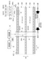
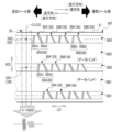
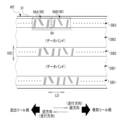
- servo bands SB1, SB2 and SB3 and data bands DB1 and DB2 are formed on the surface 31 of the magnetic tape MT0.
- the servo bands SB1 to SB3 will be referred to as the servo band SB
- the data bands DB1 and DB2 will be referred to as the data band DB, unless they need to be distinguished.
- the servo bands SB1 to SB3 and the data bands DB1 and DB2 are formed along the longitudinal direction LD (that is, the total length direction) of the magnetic tape MT0.
- the full length direction of the magnetic tape MT0 refers to the traveling direction of the magnetic tape MT0.
- the running direction of the magnetic tape MT0 is the forward direction (hereinafter also simply referred to as the "forward direction") in which the magnetic tape MT0 runs from the side of the delivery reel 22 to the side of the take-up reel 38, and the direction in which the magnetic tape MT0 runs along the take-up reel. It is defined by two directions, ie, the reverse direction (hereinafter also simply referred to as the “reverse direction”), which is the direction of running from the 38 side to the delivery reel 22 side.
- the servo bands SB1 to SB3 are arranged at positions spaced apart in the width direction WD of the magnetic tape MT0 (hereinafter also simply referred to as "width direction WD").
- the servo bands SB1 to SB3 are arranged at regular intervals along the width direction WD.
- the “equidistant interval” means an error that is generally allowed in the technical field to which the technology of the present disclosure belongs, in addition to perfectly equal intervals. It refers to equal intervals in the sense of including errors to the extent that they do not occur.
- the data band DB1 is arranged between the servo bands SB1 and SB2, and the data band DB2 is arranged between the servo bands SB2 and SB3. That is, the servo bands SB and the data bands DB are alternately arranged along the width direction WD.
- three servo bands SB and two data bands DB are shown for convenience of explanation, but this is only an example, and two servo bands SB and one data band DB are shown.
- the technique of the present disclosure can be established even if the number of data bands DB is one, or four or more servo bands SB and three or more data bands DB.
- a plurality of servo patterns 52 are recorded on the servo band SB along the longitudinal direction LD of the magnetic tape MT0.
- the servo patterns 52 are classified into servo patterns 52A and servo patterns 52B.
- a plurality of servo patterns 52 are arranged at regular intervals along the longitudinal direction LD of the magnetic tape MT0.
- constant means an error that is generally allowed in the technical field to which the technology of the present disclosure belongs, in addition to being completely constant, and is not contrary to the spirit of the technology of the present disclosure. It refers to constant in the sense of including the error of
- the servo band SB is divided by a plurality of frames 50 along the longitudinal direction LD of the magnetic tape MT0.
- a frame 50 is defined by a set of servo patterns 52 .
- servo patterns 52A and 52B are shown as an example of the set of servo patterns 52.
- the servo patterns 52A and 52B are adjacent to each other along the longitudinal direction LD of the magnetic tape MT0. 52B is located.
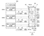
- the servo pattern 52 consists of linear magnetized region pairs 54 .
- the linear magnetization region pair 54 is classified into a linear magnetization region pair 54A and a linear magnetization region pair 54B.
- the servo pattern 52A consists of a linear magnetized region pair 54A.
- linear magnetization regions 54A1 and 54A2 are shown as an example of the linear magnetization region pair 54A.
- Each of the linearly magnetized regions 54A1 and 54A2 is a linearly magnetized region.
- the linear magnetization regions 54A1 and 54A2 are inclined in opposite directions with respect to a virtual straight line C1, which is a virtual straight line along the width direction WD.
- the linear magnetized regions 54A1 and 54A2 are tilted line-symmetrically with respect to the imaginary straight line C1. More specifically, the linear magnetized regions 54A1 and 54A2 are non-parallel to each other, and are arranged at a predetermined angle (for example, 5 degree) is formed in an inclined state.
- the virtual straight line C1 is an example of the "first virtual straight line” and the "second virtual straight line” according to the technology of the present disclosure.
- the linear magnetization region 54A1 is a set of magnetization straight lines 54A1a that are five magnetized straight lines.
- the linear magnetization region 54A2 is a set of magnetization straight lines 54A2a that are five magnetized straight lines.
- the servo pattern 52B consists of a linear magnetized region pair 54B.
- linear magnetization regions 54B1 and 54B2 are shown as an example of the linear magnetization region pair 54B.
- Each of the linearly magnetized regions 54B1 and 54B2 is a linearly magnetized region.
- the linear magnetization regions 54B1 and 54B2 are inclined in opposite directions with respect to a virtual straight line C2 that is a virtual straight line along the width direction WD.
- the linear magnetized regions 54B1 and 54B2 are tilted line-symmetrically with respect to the virtual straight line C2. More specifically, the linearly magnetized regions 54B1 and 54B2 are non-parallel to each other, and have a predetermined angle (for example, 5 degree) is formed in an inclined state.
- the virtual straight line C2 is an example of the "first virtual straight line" according to the technology of the present disclosure.
- the linear magnetization region 54B1 is a set of magnetization straight lines 54B1a that are four magnetized straight lines.
- the linear magnetization region 54B2 is a set of magnetization straight lines 54B2a that are four magnetized straight lines.
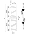
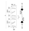
- a magnetic head 28 is arranged on the surface 31 side of the magnetic tape MT0 configured in this way.
- the holder 44 is formed in a rectangular parallelepiped shape, and is arranged so as to traverse the surface 31 of the magnetic tape MT0 along the width direction WD.
- a plurality of magnetic elements of the magnetic element unit 42 are linearly arranged along the longitudinal direction of the holder 44 .
- the magnetic element unit 42 has a pair of servo read elements SR and a plurality of data read/write elements DRW as a plurality of magnetic elements.
- the longitudinal length of the holder 44 is sufficiently long with respect to the width of the magnetic tape MT0. For example, the length of the holder 44 in the longitudinal direction exceeds the width of the magnetic tape MT0 regardless of where the magnetic element unit 42 is placed on the magnetic tape MT.
- a pair of servo read elements SR consists of servo read elements SR1 and SR2.
- the servo read element SR1 is arranged at one end of the magnetic element unit 42, and the servo read element SR2 is arranged at the other end of the magnetic element unit 42.
- the servo read element SR1 is provided at a position corresponding to the servo band SB2
- the servo read element SR2 is provided at a position corresponding to the servo band SB3.
- a plurality of data read/write elements DRW are arranged linearly between the servo read element SR1 and the servo read element SR2.
- the plurality of data read/write elements DRW are arranged at intervals along the longitudinal direction of the magnetic head 28 (for example, arranged at equal intervals along the longitudinal direction of the magnetic head 28).
- a plurality of data read/write elements DRW are provided at positions corresponding to the data band DB2.
- the control device 30 acquires a servo signal that is the result of reading the servo pattern 52 by the servo reading element SR, and performs servo control according to the acquired servo signal.
- servo control refers to control for moving the magnetic head 28 in the width direction WD of the magnetic tape MT0 by operating the moving mechanism 48 according to the servo pattern 52 read by the servo reading element SR.
- the plurality of data read/write elements DRW are positioned on the designated area within the data band DB, and magnetically process the designated area within the data band DB.
- magnetic processing is performed by a plurality of data read/write elements DRW on a designated area within the data band DB2.
- the moving mechanism 48 changes the positions of the pair of servo reading elements SR by moving the magnetic head 28 in the width direction WD under the control of the control device 30 . That is, the moving mechanism 48 moves the magnetic head 28 in the width direction WD to move the servo reading element SR1 to a position corresponding to the servo band SB1, and move the servo reading element SR2 to a position corresponding to the servo band SB2.
- TDS Transverse Dimensional Stability
- FIG. 7 shows a state in which the width of the magnetic tape MT0 has shrunk over time.
- off-track occurs.
- the width of the magnetic tape MT0 may be widened, and in this case also off-track occurs. That is, when the width of the magnetic tape MT0 shrinks or expands over time, the position of the servo reading element SR with respect to the servo pattern 52 is determined by design (for example, the linear magnetized regions 54A1, 54A2, 54B1 and 54B1). 54B2) in the width direction WD.
- the magnetic head 28 has a rotation axis RA.
- the rotation axis RA is provided at a position corresponding to the central portion of the magnetic element unit 42 included in the magnetic head 28 in plan view.
- the magnetic head 28 is rotatably held by a tilt mechanism 49 via a rotation axis RA.
- the magnetic head 28 is provided with a virtual straight line C3, which is a virtual center line.
- the imaginary straight line C3 is a straight line that passes through the rotation axis RA and extends in the longitudinal direction of the magnetic head 28 in plan view (that is, the direction in which the plurality of data read/write elements DRW are arranged).
- the magnetic head 28 is held by the tilting mechanism 49 so that the virtual straight line C3 is tilted toward the longitudinal direction LD of the magnetic tape MT0 with respect to the virtual straight line C4 along the width direction WD.
- the magnetic head 28 has a posture in which the virtual straight line C3 is tilted toward the delivery reel 22 with respect to the virtual straight line C4 (that is, a posture tilted counterclockwise when viewed from the front side of the paper surface of FIG. 8). ) is held by the tilting mechanism 49 .
- the virtual straight line C3 is an example of the "third virtual straight line", "fourth virtual straight line”, "fifth virtual straight line", and "sixth virtual straight line” according to the technology of the present disclosure.
- the tilt mechanism 49 rotates the magnetic head 28 around the rotation axis RA on the surface 31 of the magnetic tape MT0 by receiving power from a tilt actuator 49A (see FIG. 5).
- the tilt mechanism 49 rotates the magnetic head 28 around the rotation axis RA on the surface 31 of the magnetic tape MT0 under the control of the control device 30, thereby tilting the virtual straight line C3 with respect to the virtual straight line C4 (that is, azimuth ) direction and angle of inclination.
- the direction and angle of inclination of the imaginary straight line C3 with respect to the imaginary straight line C4 may vary depending on temperature, humidity, pressure with which the magnetic tape MT0 is wound around the reel, deterioration over time, etc., or expansion and contraction of the magnetic tape MT in the width direction WD due to these factors. changed according to As a result, the position of the servo reading element SR with respect to the servo pattern 52 is held at a predetermined position determined by design.
- the servo reading element SR is formed linearly along the imaginary straight line C3. Therefore, when the servo pattern 52A is read by the servo reading element SR, in the linear magnetization region pair 54A, the angle between the linear magnetization region 54A1 and the servo reading element SR and the angle between the linear magnetization region 54A2 and the servo reading element SR The angle formed by is different. When the angles are different in this way, the servo signal originating from the linear magnetization region 54A1 (that is, the servo signal obtained by reading the linear magnetization region 54A1 by the servo reading element SR) and the linear magnetization region 54A2.
- Variation due to azimuth loss between the servo signal that is, the servo signal obtained by reading the linear magnetization region 54A2 by the servo reading element SR
- the angle formed by the servo reading element SR and the linear magnetization region 54A1 is larger than the angle formed by the servo reading element SR and the linear magnetization region 54A2. This also causes variations in servo signals read by the servo reading element SR across the servo band SB while the magnetic tape MT is running.
- the linear magnetized region 54A1 is parallel to the imaginary straight line C1, and the linear magnetized region 54A2 is inclined with respect to the imaginary straight line C1 (that is, A mode in which only the linear magnetization region 54A2 is inclined) is conceivable.
- the servo pattern 52A is read by the servo reading element SR, in the linear magnetization region pair 54A, the angle formed by the linear magnetization region 54A1 and the servo reading element SR and the linear magnetization region 54A2 and the servo reading element SR are different.
- a magnetic tape MT is adopted in this embodiment as shown in FIG. 9 as an example.
- the magnetic tape MT differs from the magnetic tape MT0 in that it has a frame 56 instead of the frame 50 .
- a frame 56 is defined by a set of servo patterns 58 .
- a plurality of servo patterns 58 are recorded on the servo band SB along the longitudinal direction LD of the magnetic tape MT.
- the plurality of servo patterns 58 are arranged at regular intervals along the longitudinal direction LD of the magnetic tape MT, like the plurality of servo patterns 52 recorded on the magnetic tape MT0.
- servo patterns 58A and 58B are shown as an example of a set of servo patterns 58 included in the frame 56.
- the servo patterns 58A and 58B are adjacent to each other along the longitudinal direction LD of the magnetic tape MT. 58B is located.
- the servo pattern 58 consists of linear magnetized region pairs 60 .
- the linear magnetization region pair 60 is classified into a linear magnetization region pair 60A and a linear magnetization region pair 60B.
- the linear magnetization region pair 60 is an example of the "linear magnetization region pair" according to the technology of the present disclosure.
- the servo pattern 58A consists of a linear magnetization region pair 60A.
- linear magnetization regions 60A1 and 60A2 are shown as an example of the linear magnetization region pair 60A.
- Each of the linearly magnetized regions 60A1 and 60A2 is a linearly magnetized region.
- the linear magnetization region 60A1 is an example of the “first linear magnetization region” according to the technology of the present disclosure
- the linear magnetization region 60A2 is the “second linear magnetization region” according to the technology of the present disclosure. This is an example of "area”.
- the linear magnetization regions 60A1 and 60A2 are inclined in opposite directions with respect to the imaginary straight line C1.
- the linear magnetization region 60A1 is inclined in one direction (for example, clockwise when viewed from the front side of the paper surface of FIG. 9) with respect to the virtual straight line C1.
- the linearly magnetized region 60A2 is inclined in another direction (for example, counterclockwise when viewed from the front side of the paper surface of FIG. 9) with respect to the virtual straight line C1.
- the linear magnetized regions 60A1 and 60A2 are non-parallel to each other and inclined at different angles with respect to the virtual straight line C1.
- the linear magnetization region 60A1 has a steeper inclination angle with respect to the virtual straight line C1 than the linear magnetization region 60A2.
- “steep” means, for example, that the angle of the linear magnetization region 60A1 with respect to the virtual straight line C1 is smaller than the angle of the linear magnetization region 60A2 with respect to the virtual straight line C1. Also, the total length of the linear magnetization region 60A1 is shorter than the total length of the linear magnetization region 60A2.
- the linear magnetization region 60A1 includes a plurality of magnetization straight lines 60A1a
- the linear magnetization region 60A2 includes a plurality of magnetization straight lines 60A2a.
- the number of magnetization straight lines 60A1a included in the linear magnetization region 60A1 is the same as the number of magnetization straight lines 60A2a included in the linear magnetization region 60A2.
- the linear magnetization region 60A1 is a set of five magnetized straight lines 60A1a
- the linear magnetization region 60A2 is a set of five magnetized straight lines 60A2a.
- the positions of both ends of the linear magnetization region 60A1 that is, the positions of both ends of each of the five magnetization straight lines 60A1a
- the positions of both ends of the linear magnetization region 60A2 that is, five (positions of both ends of each magnetization line 60A2a
- an example is given in which the positions of both ends of each of the five magnetization straight lines 60A1a and the positions of both ends of each of the five magnetization straight lines 60A2a are aligned, but this is merely an example.
- the positions of both ends of one or more magnetization straight lines 60A1a out of the five magnetization straight lines 60A1a and the positions of both ends of one or more of the five magnetization straight lines 60A2a may be aligned.
- the concept of "aligned” includes, in addition to the meaning of being completely aligned, an error that is generally allowed in the technical field to which the technology of the present disclosure belongs. It also includes the meaning of "aligned” including errors that do not go against the purpose of the technology.
- the servo pattern 58B consists of a linear magnetized region pair 60B.
- linear magnetization regions 60B1 and 60B2 are shown as an example of the linear magnetization region pair 60B.
- Each of the linearly magnetized regions 60B1 and 60B2 is a linearly magnetized region.
- the linear magnetization region 60B1 is an example of the "first linear magnetization region” according to the technology of the present disclosure
- the linear magnetization region 60B2 is the “second linear magnetization region” according to the technology of the present disclosure. This is an example of "area”.
- the linear magnetization regions 60B1 and 60B2 are inclined in opposite directions with respect to the imaginary straight line C2.
- the linear magnetization region 60B1 is inclined in one direction (for example, clockwise when viewed from the front side of the paper surface of FIG. 9) with respect to the virtual straight line C2.
- the linearly magnetized region 60B2 is inclined in another direction (for example, counterclockwise when viewed from the front side of the paper surface of FIG. 9) with respect to the virtual straight line C2.
- the linear magnetized regions 60B1 and 60B2 are non-parallel to each other and inclined at different angles with respect to the virtual straight line C2.
- the linear magnetization region 60B1 has a steeper inclination angle with respect to the virtual straight line C2 than the linear magnetization region 60B2.
- “steep” means, for example, that the angle of the linear magnetization region 60B1 with respect to the virtual straight line C2 is smaller than the angle of the linear magnetization region 60B2 with respect to the virtual straight line C2. Also, the total length of the linear magnetization region 60B1 is shorter than the total length of the linear magnetization region 60B2.
- the linear magnetization region 60B1 includes a plurality of magnetization straight lines 60B1a
- the linear magnetization region 60B2 includes a plurality of magnetization straight lines 60B2a.
- the number of magnetization straight lines 60B1a included in the linear magnetization region 60B1 is the same as the number of magnetization straight lines 60B2a included in the linear magnetization region 60B2.
- the total number of magnetization straight lines 60B1a and 60B2a included in the servo pattern 58B is different from the total number of magnetization straight lines 60A1a and 60A2a included in the servo pattern 58A.
- the total number of magnetization straight lines 60A1a and 60A2a included in the servo pattern 58A is ten, while the total number of magnetization straight lines 60B1a and 60B2a included in the servo pattern 58B is eight.
- the linear magnetization region 60B1 is a set of four magnetized straight lines 60B1a
- the linear magnetization region 60B2 is a set of four magnetized straight lines 60B2a.
- the positions of both ends of the linear magnetization region 60B1 that is, the positions of both ends of each of the four magnetization straight lines 60B1a
- the positions of both ends of the linear magnetization region 60B2 that is, four (positions of both ends of each magnetization line 60B2a) are aligned.
- a set of magnetization straight lines 60A1a that are five magnetized straight lines is given, and as an example of the linear magnetization region 60A2, a magnetization line that is five magnetization straight lines is given.
- a set of straight lines 60A2a is mentioned, the technology of the present disclosure is not limited to this.
- An example of the linear magnetization region 60B1 is a set of four magnetized straight lines 60B1a
- an example of the linear magnetization region 60B2 is a set of four magnetization straight lines 60B2a.
- a set is mentioned, the technology of the present disclosure is not limited to this.
- the linear magnetization region 60A1 is the number of magnetization straight lines 60A1a that contribute to specifying the position of the magnetic head 28 on the magnetic tape MT
- the linear magnetization region 60A2 is the number of the magnetic head 28 on the magnetic tape MT.
- the technology of the present disclosure is established as long as the number of magnetization straight lines 60A2a contributes to a specific number.
- the linear magnetization regions 60B1 are the number of magnetization straight lines 60B1a that contribute to specifying the position of the magnetic head 28 on the magnetic tape MT.
- the technology of the present disclosure is established as long as the number of magnetization straight lines 60B2a contributes to specificity.
- geometric properties refer to generally recognized geometric properties such as length, shape, orientation, and/or position.
- the geometric characteristics of the linear magnetization region pair 60A on the magnetic tape MT can be expressed using a virtual linear region pair 62.
- the virtual linear region pair 62 consists of a virtual linear region 62A and a virtual linear region 62B.
- the geometrical characteristics of the pair of linear magnetized regions 60A on the magnetic tape MT are such that the axis of symmetry SA1 of the virtual linear regions 62A and 62B, which are tilted in line symmetry with respect to the virtual straight line C1, is set with respect to the virtual straight line C1.
- the virtual linear region pair 62 is an example of the “pair of virtual linear regions” according to the technology of the present disclosure
- the virtual linear region 62A is the “one virtual line region” according to the technology of the present disclosure
- the virtual linear region 62B is an example of the “other virtual linear region” according to the technology of the present disclosure.
- the virtual linear region pair 62 is a virtual linear magnetized region pair having the same geometric characteristics as the linear magnetized region pair 54A shown in FIG.
- the imaginary linear region pair 62 is a virtual magnetized region used for convenience in explaining the geometric characteristics of the linear magnetized region pair 60A on the magnetic tape MT, and is not an actual magnetized region.
- the virtual linear region 62A has the same geometrical characteristics as the linear magnetization region 54A1 shown in FIG. 6, and consists of five virtual straight lines 62A1 corresponding to the five magnetization straight lines 54A1a shown in FIG.
- the imaginary linear region 62B has the same geometric characteristics as the linear magnetization region 54B1 shown in FIG. 6, and consists of five imaginary straight lines 62B1 corresponding to the five magnetization straight lines 54A2a shown in FIG.
- the virtual linear region pair 62 is provided with a center O1.
- the center O1 is the center of the straight line 62A1 positioned most upstream in the forward direction among the five straight lines 62A1 and the center of the straight line 62B1 positioned most downstream in the forward direction among the five straight lines 62B1. is the center of the line segment L0 connecting the
- the virtual linear region pair 62 has the same geometric characteristics as the linear magnetized region pair 54A shown in FIG. ing.
- the entire virtual linear region pair 62 is formed into a virtual straight line.
- the virtual linear region 62A is read, but the virtual linear region 62B is not read, or the virtual linear region 62A is not read, but the virtual linear region 62A is not read.
- the linear region 62B has a portion that is read. That is, in each of the imaginary linear regions 62A and 62B, when reading by the servo reading element SR is performed, a missing portion and an unnecessary portion are generated.
- the geometrical characteristics of the virtual linear region pair 62 obtained in this way correspond to the geometrical characteristics of the actual servo pattern 58A. That is, the servo band SB corresponds to the geometric characteristic of the virtual linear region pair 62 obtained by aligning the positions of both ends of the virtual linear region 62A and the positions of both ends of the virtual linear region 62B in the width direction WD.
- the linear magnetization region pair 60B Compared to the linear magnetization region pair 60A, the linear magnetization region pair 60B has four magnetization lines 60B1a instead of the five magnetization lines 60A1a, and has four magnetization lines 60A2a instead of the five magnetization lines 60A2a. The only difference is that it has a straight line of magnetization 60B2a. Therefore, in the servo band SB, a pair of imaginary linear regions ( omitted) are recorded.
- a plurality of servo bands SB are formed in the width direction WD on the magnetic tape MT.
- the frames 56 corresponding to each other between the servo bands SB are shifted at predetermined intervals in the longitudinal direction LD of the magnetic tape MT between the adjacent servo bands SB in the width direction WD.
- This means that the servo patterns 58 having a corresponding relationship between the servo bands SB are shifted at predetermined intervals in the longitudinal direction LD of the magnetic tape MT between the servo bands SB adjacent in the width direction WD.
- the predetermined interval is defined based on the angle ⁇ , the pitch between adjacent servo bands SB in the width direction WD (hereinafter also referred to as "servo band pitch"), and the frame length.
- the angle ⁇ is exaggerated to make it easier to visually grasp the angle ⁇ , but in reality the angle ⁇ is, for example, about 15 degrees.
- the angle ⁇ is the angle formed between the frames 56 having no corresponding relationship between the adjacent servo bands SB in the width direction WD and the imaginary straight line C1.
- one frame 56 in the example shown in FIG. 11, the servo band SB3
- the other frame 56 of the pair of frames 56 in the example shown in FIG.
- the frame length refers to the total length of the frame 56 in the longitudinal direction LD of the magnetic tape MT.
- the default interval is defined by Equation (1) below. Note that Mod (A/B) means the remainder produced when "A" is divided by "B".
- one frame 56 (hereinafter also referred to as "first frame") of a pair of frames 56 having a corresponding relationship between servo bands SB adjacent in the width direction WD is set as the angle ⁇ .
- the frame 56 adjacent to the other frame 56 (hereinafter also referred to as “second frame”) of the pair of frames 56 and the virtual straight line C1.
- the angle ⁇ is an imaginary straight line between a first corresponding frame and a frame 56 (hereinafter also referred to as a “third frame”) which is two frames or more away from the second frame within the same servo band SB as the second frame. It may be an angle formed with C1.
- the "frame length" used in equation (1) is the pitch between the second and third frames in the longitudinal direction LD of the magnetic tape MT (for example, the distance from the top of the second frame to the third frame). distance to the tip).
- servo reading is performed in a state in which the direction of the virtual straight line C1 and the direction of the virtual straight line C3 match (that is, the state in which the longitudinal direction of the magnetic head 28 matches the width direction WD).
- the servo pattern 58A that is, the linear magnetization region pair 60A
- the servo pattern 58B that is, a similar phenomenon occurs when the linear magnetization region pair 60B is read.
- the tilting mechanism 49 (see FIG. 8) is arranged such that the imaginary straight line C3 is directed upstream at an angle ⁇ (that is, when viewed from the front side of FIG. 13) with respect to the imaginary straight line C1.
- the magnetic head 28 is skewed on the magnetic tape MT about the rotation axis RA so as to be inclined by an angle ⁇ ) counterclockwise in the case. In this way, since the magnetic head 28 is tilted at an angle ⁇ upstream in the forward direction on the magnetic tape MT, compared to the example shown in FIG. Variation due to azimuth loss between the servo signal and the servo signal is reduced.
- the servo pattern 58B that is, the linear magnetization region pair 60B
- the servo signal derived from the linear magnetization region 60B1 and the servo signal derived from the linear magnetization region 60B2 are similarly read. Variation due to azimuth loss between signals is reduced.
- the angle ⁇ is obtained by rotating the axis of symmetry SA1 (see FIG. 10) of the imaginary linear regions 62A and 62B (see FIG. 10) with respect to the imaginary straight line C1 with the center O1 (see FIG. 10) as the rotation axis. It is set to coincide with the angle a (see FIG. 10) which is the angle shown in FIG.
- "match” means, in addition to perfect match, an error that is generally allowed in the technical field to which the technology of the present disclosure belongs, and is not contrary to the spirit of the technology of the present disclosure.
- the geometric properties of the imaginary linear regions 62A and 62B are the same as the geometric properties of the linear magnetized regions 60A1 and 60A2. Accordingly, the linear magnetized regions 60A1 and 60A2 are also inclined at an angle a with respect to the imaginary straight line C1. In this case, when the magnetic head 28 is tilted upstream in the forward direction on the magnetic tape MT at an angle ⁇ (that is, an angle a), the tilt angle of the magnetic head 28 and the tilt angles of the linear magnetized regions 60A1 and 60A2 match. do.
- the control device 30 has a control section 30A and a position detection section 30B.
- the position detection section 30B has a first position detection section 30B1 and a second position detection section 30B2.
- the position detector 30B acquires a servo signal as a result of reading the servo pattern 58 by the servo reading element SR, and detects the position of the magnetic head 28 on the magnetic tape MT based on the acquired servo signal.
- a servo signal is classified into a first servo signal and a second servo signal.
- the first servo signal is the result of reading the servo pattern 58 by the servo reading element SR1
- the second servo signal is the result of reading the servo pattern 58 by the servo reading element SR2. be.
- the first position detection section 30B1 acquires the first servo signal
- the second position detection section 30B2 acquires the second servo signal.
- the first position detection section 30B1 acquires the first servo signal obtained by reading the servo pattern 58 in the servo band SB2 with the servo reading element SR1
- the second position detection section 30B2 acquires the first servo signal. obtains a second servo signal obtained by reading the servo pattern 58 in the servo band SB3 by the servo reading element SR2.
- the first position detection section 30B1 detects the position of the servo reading element SR1 with respect to the servo band SB2 based on the first servo signal
- the second position detection section 30B2 detects the position with respect to the servo band SB3 based on the second servo signal.
- the position of servo read element SR2 is detected.
- the control unit 30A receives the position detection result of the first position detection unit 30B1 (that is, the position detection result of the first position detection unit 30B1) and the position detection result of the second position detection unit 30B2 (that is, the second position detection unit 30B1).
- Various controls are performed based on the result of position detection by the position detector 30B2.
- various controls refer to, for example, servo control, skew angle control, and/or tension control.
- Tension control refers to control of tension applied to the magnetic tape MT (for example, tension for reducing the effect of TDS).
- the position detection unit 30B detects the servo signal, which is the result of reading the servo pattern 58 from the magnetic tape MT by the servo reading element SR, using the autocorrelation coefficient.
- the ideal waveform signal 66 is stored in the storage 32 .
- the ideal waveform signal 66 is a signal indicating a single-shot ideal waveform included in the servo signal (for example, an ideal waveform obtained by reading one ideal magnetization straight line included in the servo pattern 58 by the servo reading element SR). signal).
- the ideal waveform signal 66 can also be said to be a sample signal to be compared with the servo signal. It should be noted that here, an example of the form in which the ideal waveform signal 66 is stored in the storage 32 is given, but this is merely an example.
- Signal 66 may be stored in cartridge memory 24 .
- the ideal waveform signal 66 may be recorded in a BOT area (not shown) provided at the beginning of the magnetic tape MT and/or an EOT area (not shown) provided at the end of the magnetic tape MT.
- the autocorrelation coefficient used by the position detection section 30B is a coefficient that indicates the degree of correlation between the servo signal and the ideal waveform signal 66.
- the position detector 30B acquires the ideal waveform signal 66 from the storage 32 and compares the acquired ideal waveform signal 66 with the servo signal. Then, the position detection section 30B calculates an autocorrelation coefficient based on the comparison result.
- the position detector 30B detects a position where the servo signal and the ideal waveform signal 66 are highly correlated on the servo band SB (for example, a position where the servo signal and the ideal waveform signal 66 match) according to the autocorrelation coefficient. .
- the position of the servo reading element SR with respect to the servo band SB is detected, for example, based on the interval in the longitudinal direction LD between the servo patterns 58A and 58B.
- the longitudinal LD spacing of the servo patterns 58A and 58B is detected according to the autocorrelation coefficient.
- the position detection unit 30B detects the interval between the linear magnetized regions 60A1 and 60A2 and the interval between the linear magnetized regions 60B1 and 60B2 detected according to the autocorrelation coefficient. is used to detect the position of the servo reading element SR with respect to the servo band SB.
- the control unit 30A adjusts the position of the magnetic head 28 by operating the moving mechanism 48 based on the position detection result of the position detection unit 30B (that is, the position detection result of the position detection unit 30B). Further, the control section 30A causes the magnetic element unit 42 to perform magnetic processing on the data band DB of the magnetic tape MT. That is, the control unit 30A acquires a read signal from the magnetic element unit 42 (that is, data read from the data band DB of the magnetic tape MT by the magnetic element unit 42) and supplies a recording signal to the magnetic element unit 42. Thus, data corresponding to the recording signal is recorded on the data band DB of the magnetic tape MT.
- control unit 30A calculates the servo band pitch from the position detection result of the position detection unit 30B, and performs tension control according to the calculated servo band pitch, or , the magnetic head 28 is skewed.
- Tension control is realized by adjusting the rotational speed and rotational torque of each of the delivery motor 36 and the winding motor 40 . Skew of the magnetic head 28 is achieved by operating the tilt mechanism 49 .
- a servo writer SW is used in the servo pattern recording process.
- the servo writer SW includes a delivery reel SW1, a take-up reel SW2, a drive device SW3, a pulse signal generator SW4, a control device SW5, a plurality of guides SW6, a transport path SW7, a servo pattern recording head WH, and a verify head VH.
- the servo writer SW is an example of the "servo pattern recording device” and the “inspection device” according to the technology of the present disclosure.
- the pulse signal generator SW4 is an example of the "pulse signal generator” according to the technology of the present disclosure.
- the servo pattern recording head WH is an example of the "servo pattern recording head” according to the technique of the present disclosure.
- the control device SW5 is an example of the “inspection processor” according to the technology of the present disclosure.
- the control device SW5 controls the entire servo writer SW.
- the control device SW5 is implemented by an ASIC, but the technology of the present disclosure is not limited to this.
- the control device SW5 may be realized by FPGA and/or PLC.
- the control device SW5 may be implemented by a computer including a CPU, flash memory (eg, EEPROM and/or SSD, etc.), and RAM. Also, it may be realized by combining two or more of ASIC, FPGA, PLC, and computer. That is, the control device SW5 may be realized by a combination of hardware configuration and software configuration.
- a pancake is set on the delivery reel SW1.
- a pancake refers to a large-diameter roll in which a magnetic tape MT cut into a product width from a wide raw web is wound around a hub before the servo pattern 58 is written.
- the driving device SW3 has a motor (not shown) and a gear (not shown), and is mechanically connected to the delivery reel SW1 and the take-up reel SW2.
- the driving device SW3 When the magnetic tape MT is wound by the take-up reel SW2, the driving device SW3 generates power according to instructions from the control device SW5, and transmits the generated power to the delivery reel SW1 and the take-up reel SW2 to deliver the magnetic tape MT.
- the reel SW1 and the take-up reel SW2 are rotated. That is, the delivery reel SW1 receives power from the driving device SW3 and rotates to deliver the magnetic tape MT to the predetermined transport path SW7.
- the take-up reel SW2 is powered by the driving device SW3 and rotates, thereby winding up the magnetic tape MT delivered from the delivery reel SW1.
- the rotational speed and rotational torque of the delivery reel SW1 and the take-up reel SW2 are adjusted according to the speed at which the magnetic tape MT is wound onto the take-up reel SW2.
- a plurality of guides SW6 and servo pattern recording heads WH are arranged on the transport path SW7.
- the servo pattern recording head WH is arranged on the surface 31 side of the magnetic tape MT between the guides SW6.
- the magnetic tape MT sent out from the delivery reel SW1 to the transport path SW7 is guided by a plurality of guides SW6, passes over the servo pattern recording head WH, and is taken up by the take-up reel SW2.
- the manufacturing process of the magnetic tape MT includes a plurality of processes in addition to the servo pattern recording process.
- the multiple processes include an inspection process and a winding process.
- the inspection process is a process of inspecting the servo band SB formed on the surface 31 of the magnetic tape MT by the servo pattern recording head WH.
- the inspection of the servo band SB refers to, for example, a process of determining whether the servo patterns 58 recorded on the servo band SB are correct. Determining whether the servo patterns 58 are correct or not means that, for example, the servo patterns 58A and 58B correspond to predetermined positions on the surface 31, and the magnetization straight lines 60A1a, 60A2a, 60B1a, and 60B2a are neither excessive nor deficient, and there is an allowable error. (that is, verification of the servo pattern 58).
- the inspection process is performed by using the control device SW5 and the verify head VH.
- the verify head VH is arranged downstream of the servo pattern recording head WH in the conveying direction of the magnetic tape MT.
- the verify head VH is provided with a plurality of servo reading elements (not shown) in the same manner as the magnetic head 28, and the plurality of servo reading elements read a plurality of servo bands SB. Further, the verify head VH is skewed on the surface 31 of the magnetic tape MT, similarly to the magnetic head 28 .
- the verify head VH is connected to the control device SW5.
- the verify head VH is arranged at a position directly facing the servo band SB when viewed from the surface 31 side of the magnetic tape MT (that is, the rear side of the verify head VH), and the servo patterns recorded on the servo band SB are arranged on the verify head VH.
- 58 is read, and the read result (hereinafter referred to as "servo pattern read result”) is output to the control device SW5.
- the control device SW5 inspects the servo band SB (for example, determines whether the servo pattern 58 is correct or not) based on the servo pattern reading result (for example, servo signal) input from the verify head VH.
- the control device SW5 operates as the position detection unit 30B shown in FIG. 14 to obtain the position detection result from the servo pattern reading result, and determines whether the servo pattern 58 is correct or not by using the position detection result. SB is inspected.
- the control device SW5 sends information indicating the result of inspecting the servo band SB (for example, the result of determining whether the servo pattern 58 is correct or not) to a predetermined output destination (for example, the storage 32 (see FIG. 3), the UI system device 34 (see FIG. 3), or the like. 3) and/or to an external device 37 (see FIG. 3), etc.).
- a predetermined output destination for example, the storage 32 (see FIG. 3), the UI system device 34 (see FIG. 3), or the like.
- the winding process is performed next.
- the delivery reel 22 used for each of the plurality of magnetic tape cartridges 12 that is, the delivery reel accommodated in the magnetic tape cartridge 12 (see FIGS. 1 to 4) 22 (see FIGS. 2 to 4)) to wind the magnetic tape MT.
- a winding motor M is used in the winding process.
- the take-up motor M is mechanically connected to the delivery reel 22 via a gear or the like.
- the take-up motor M rotates the delivery reel 22 by applying a rotational force to the delivery reel 22 under the control of a control device (not shown).
- the magnetic tape MT wound on the take-up reel SW2 is wound on the delivery reel 22 as the delivery reel 22 rotates.
- a cutting device (not shown) is used in the winding process. For each of the plurality of delivery reels 22, when the required amount of magnetic tape MT is wound by the delivery reel 22, the magnetic tape MT delivered from the take-up reel SW2 to the delivery reel 22 is cut by the cutting device.
- the pulse signal generator SW4 generates a pulse signal under the control of the control device SW5 and supplies the generated pulse signal to the servo pattern recording head WH. While the magnetic tape MT is running on the transport path SW7 at a constant speed, the servo pattern recording head WH records the servo pattern 58 on the servo band SB according to the pulse signal supplied from the pulse signal generator SW4.
- FIG. 17 shows the servo pattern recording when the servo pattern recording head WH is observed from the front surface 31 side (that is, the back side of the servo pattern recording head WH) of the magnetic tape MT traveling on the transport path SW7 (see FIG. 16).
- An example of the configuration of the head WH and an example of the configuration of the pulse signal generator SW4 are shown.
- the servo pattern recording head WH has a substrate WH1 and a plurality of head cores WH2.
- the substrate WH1 is formed in a rectangular parallelepiped shape, and is arranged so as to traverse along the width direction WD the surface 31 of the magnetic tape MT traveling on the transport path SW7.
- the surface WH1A of the substrate WH1 is a rectangle having long sides WH1Aa and short sides WH1Ab, and the long sides WH1Aa cross the surface 31 of the magnetic tape MT along the width direction WD.
- the surface WH1A has a sliding surface WH1Ax.
- the sliding surface WH1Ax is a surface (for example, in FIG. dot-shaped hatched area shown).
- the sliding surface WH1Ax slides on the running magnetic tape MT.
- the width of the sliding surface WH1Ax (that is, the length in the direction LD1 corresponding to the longitudinal direction LD (for example, the same direction as the longitudinal direction LD)) shown in FIG. 17 is merely an example. may be several times wider than the example shown in FIG.
- a direction WD1 (that is, the direction along the long side WH1Aa) that is the longitudinal direction of the substrate WH1 is a direction corresponding to the width direction WD (for example, the same direction as the width direction WD).
- a plurality of head cores WH2 are incorporated in the base body WH1 along the direction WD1.
- a gap pattern G is formed in the head core WH2.
- the gap pattern G is formed on the surface WH1A (that is, the surface of the substrate WH1 facing the surface 31 of the magnetic tape MT). Also, the gap pattern G consists of a pair of non-parallel linear regions.
- a pair of non-parallel linear regions is, for example, the same geometric characteristics as the magnetization straight line 60A1a located on the most upstream side in the forward direction among the five magnetization straight lines 60A1a included in the linear magnetization region 60A1 shown in FIG.
- a plurality of gap patterns G are formed along the direction WD1 on the surface WH1A.
- the spacing in the direction WD1 between the gap patterns G adjacent in the direction WD1 corresponds to the spacing in the width direction WD between the servo bands SB of the magnetic tape MT (that is, the servo band pitch).
- a coil (not shown) is wound around the head core WH2, and a pulse signal is supplied to the coil.
- the pulse signals supplied to the coils are a pulse signal for the servo pattern 58A and a pulse signal for the servo pattern 58B.
- the pulse signal for the servo pattern 58A is supplied to the coil of the head core WH2 in a state in which the gap pattern G faces the servo band SB of the magnetic tape MT running on the transport path SW7
- the pulse signal A magnetic field is applied from the gap pattern G to the servo band SB of the magnetic tape MT.
- the servo pattern 58A is recorded on the servo band SB.
- the pulse signal for the servo pattern 58B is supplied to the coil of the head core WH2.
- a magnetic field is applied from the gap pattern G to the servo band SB of the magnetic tape MT.
- the servo pattern 58B is recorded on the servo band SB.
- the pulse signal corresponding to each servo pattern 58 (that is, the servo pattern 58 for each frame 56 (see FIG. 9)) is modulated.
- Various information is embedded in the pulse signal by modulating the pulse signal.
- the interval hereinafter referred to as "first spacing”
- the spacing between the third magnetization straight line 60A1a and the fourth magnetization straight line 60A1a (hereinafter referred to as "second spacing") can be changed for each servo pattern 58A. becomes.
- Various information refers to, for example, information regarding the position of the magnetic tape MT in the longitudinal direction LD, information identifying the servo band SB, and/or information identifying the manufacturer of the magnetic tape MT.
- head cores WH2A, WH2B and WH2C are shown as examples of the plurality of head cores WH2, and gap patterns G1, G2 and G3 are shown as examples of the plurality of gap patterns G.
- the gap pattern G1 is formed on the head core WH2A.
- the gap pattern G2 is formed on the head core WH2B.
- the gap pattern G3 is formed on the head core WH2C.
- each of the gap patterns G1 to G3 has the same geometric characteristics.
- the gap pattern G1 is used for recording the servo pattern 58 (see FIG. 9) for the servo band SB3 (see FIG. 9)
- the gap pattern G2 is used for recording the servo pattern for the servo band SB2 (see FIG. 9).
- the gap pattern G3 is used for recording the pattern 58 (see FIG. 9)
- the gap pattern G3 is used for recording the servo pattern 58 (see FIG. 9) for the servo band SB1 (see FIG. 9).
- the gap pattern G1 is a pair of linear regions G1A and G1B.
- the gap pattern G2 is a pair of linear regions consisting of linear regions G2A and G2B.
- the gap pattern G3 is a pair of linear regions consisting of linear regions G3A and G3B.
- the linear region pair consisting of the linear regions G1A and G1B, the linear region pair consisting of the linear regions G2A and G2B, and the linear region pair consisting of the linear regions G3A and G3B are referred to as the "linear region pair is an example of Also, in the present embodiment, the linear regions G1A, G2A, and G3A are examples of the "first linear region” according to the technology of the present disclosure. Further, in the present embodiment, the linear regions G1B, G2B, and G3B are examples of the "second linear regions" according to the technology of the present disclosure.
- the pulse signal generator SW4 has a first pulse signal generator SW4A, a second pulse signal generator SW4B, and a third pulse signal generator SW4C.
- the first pulse signal generator SW4A is connected to the head core WH2A.
- the second pulse signal generator SW4B is connected to the head core WH2B.
- the third pulse signal generator SW4C is connected to the head core WH2C.
- the gap pattern G1 is used for the servo band SB3 (see FIG. 9)
- the first pulse signal generator SW4A supplies a pulse signal to the head core WH2A
- a magnetic field is generated from the gap pattern G1 to the servo band SB3 according to the pulse signal.
- a servo pattern 58 (see FIG. 9) is recorded on the servo band SB3.
- the servo band A servo pattern 58A (see FIG. 9) is recorded in SB3. That is, the linear magnetization region 60A1 (see FIG. 9) is recorded in the servo band SB3 by the linear region G1A, and the linear magnetization region 60A2 (see FIG. 9) is recorded in the servo band SB3 by the linear region G1B. .
- a servo pattern 58B (see FIG. 9) is recorded on the servo band SB3. That is, the linear magnetization region 60B1 (see FIG. 9) is recorded in the servo band SB3 by the linear region G1A, and the linear magnetization region 60B2 (see FIG. 9) is recorded in the servo band SB3 by the linear region G1B. .
- the gap pattern G2 is used for the servo band SB2 (see FIG. 9)
- the second pulse signal generator SW4B supplies a pulse signal to the head core WH2B
- a magnetic field is generated from the gap pattern G2 to the servo band SB2 according to the pulse signal.
- a servo pattern 58 is recorded on the servo band SB2.
- the servo band A servo pattern 58A (see FIG. 9) is recorded in SB2. That is, the linear magnetization region 60A1 is recorded in the servo band SB2 by the linear region G2A, and the linear magnetization region 60A2 is recorded in the servo band SB2 by the linear region G2B.
- a servo pattern 58B is recorded in the servo band SB2. That is, the linear magnetization region 60B1 is recorded in the servo band SB2 by the linear region G2A, and the linear magnetization region 60B2 is recorded in the servo band SB2 by the linear region G2B.
- the gap pattern G3 is used for the servo band SB1 (see FIG. 9)
- the third pulse signal generator SW4C supplies a pulse signal to the head core WH2C
- a magnetic field is generated from the gap pattern G3 to the servo band SB1 according to the pulse signal.
- a servo pattern 58 is recorded on the servo band SB1.
- the servo band A servo pattern 58A is recorded in SB1. That is, the linear magnetization region 60A1 is recorded in the servo band SB1 by the linear region G3A, and the linear magnetization region 60A2 is recorded in the servo band SB1 by the linear region G3B.
- a servo pattern 58B is recorded on the servo band SB1. That is, the linear magnetization region 60B1 is recorded in the servo band SB1 by the linear region G3A, and the linear magnetization region 60B2 is recorded in the servo band SB1 by the linear region G3B.
- the linear regions G1A and G1B are inclined in directions opposite to the straight line along the direction WD1, that is, the virtual straight line C1.
- the straight line region G1A is inclined in one direction (for example, clockwise when viewed from the front side of the paper surface of FIG. 18) with respect to the virtual straight line C1.
- the straight line region G1B is inclined in another direction (for example, counterclockwise when viewed from the front side of the paper surface of FIG. 18) with respect to the virtual straight line C1.
- the linear region G1A has a steeper inclination angle with respect to the virtual straight line C1 than the linear region G1B.
- steer means, for example, that the angle of the straight line region G1A with respect to the virtual straight line C1 is smaller than the angle of the straight line region G1B with respect to the virtual straight line C1. Further, the positions of both ends of the linear region G1A and the positions of both ends of the linear region G1B are aligned in the direction WD1. Also, the total length of the linear region G1A is shorter than the total length of the linear region G1B.
- the linear regions G2A and G2B are inclined in opposite directions with respect to the virtual straight line C1.
- the straight line region G2A is inclined in one direction (for example, clockwise when viewed from the front side of the paper surface of FIG. 18) with respect to the virtual straight line C1.
- the straight line region G2B is inclined in another direction (for example, counterclockwise when viewed from the front side of the paper surface of FIG. 18) with respect to the virtual straight line C1.
- the linear region G2A has a steeper inclination angle with respect to the virtual straight line C1 than the linear region G2B.
- steer means, for example, that the angle of the straight line region G2A with respect to the virtual straight line C1 is smaller than the angle of the straight line region G2B with respect to the virtual straight line C1. Further, the positions of both ends of the linear region G2A and the positions of both ends of the linear region G2B are aligned in the direction WD1. Also, the total length of the linear region G2A is shorter than the total length of the linear region G2B.
- the linear regions G3A and G3B are inclined in opposite directions with respect to the virtual straight line C1.
- the straight line region G3A is inclined in one direction (for example, clockwise when viewed from the front side of the paper surface of FIG. 18) with respect to the virtual straight line C1.
- the straight line region G3B is inclined in another direction (for example, counterclockwise when viewed from the front side of the paper surface of FIG. 18) with respect to the virtual straight line C1.
- the linear region G3A has a steeper inclination angle with respect to the virtual straight line C1 than the linear region G3B.
- steer means, for example, that the angle of the straight line region G3A with respect to the virtual straight line C1 is smaller than the angle of the straight line region G3B with respect to the virtual straight line C1. Also, the positions of both ends of the linear region G3A and the positions of both ends of the linear region G3B are aligned in the direction WD1. Also, the total length of the linear region G3A is shorter than the total length of the linear region G3B.
- the gap patterns G1, G2, and G3 are shifted in the direction LD1 between the adjacent gap patterns G along the direction WD1 by the above-described predetermined distance (that is, the predetermined distance calculated from the formula (1)).
- the long side WH1Aa is longer than the width of the magnetic tape MT.
- the short side WH1Ab has a length that accommodates all of the gap patterns G1, G2, and G3.
- the length in which all of the gap patterns G1, G2, and G3 are accommodated refers to the length in which the linear regions G1A to G3B are accommodated along the longitudinal direction LD of the magnetic tape MT.
- the direction of the long side WH1Aa matches the width direction WD
- the direction of the short side WH1Ab matches the longitudinal direction LD of the magnetic tape MT.
- the substrate WH1 is arranged on the surface 31 side of the magnetic tape MT with the plurality of gap patterns G facing the surface 31 and traversing the magnetic tape MT in the width direction WD.
- Pulse signals used between the gap patterns G1, G2 and G3 are signals of the same phase.
- the position of the gap pattern G1 corresponds to the position of the servo band SB3
- the position of the gap pattern G2 corresponds to the position of the servo band SB2
- the position of the gap pattern G3 corresponds to the position of the servo band SB1.
- the magnetic tape MT runs on the transport path SW7 at a constant speed.
- the pulse signal for the servo pattern 58A and the pulse signal for the servo pattern 58B are alternately supplied to the head core WH2A, the head core WH2B, and the head core WH2C.
- the longitudinal direction of the magnetic tape MT is applied to the servo band SB3, the servo band SB2, and the servo band SB1.
- a servo pattern 58A is recorded on the LD with a predetermined gap.
- pulse signals for the servo pattern 58B are supplied in the same phase to the head core WH2A, the head core WH2B, and the head core WH2C, the magnetic tape MT is applied to the servo band SB3, the servo band SB2, and the servo band SB1.
- the servo pattern 58B is recorded with a predetermined gap in the longitudinal direction LD.
- the geometric characteristics of the gap pattern G on the surface WH1A can be expressed using virtual straight line region pairs 68.
- the virtual linear region pair 68 consists of a virtual linear region 68A and a virtual linear region 68B.
- the virtual linear region pair 68 is an example of "a pair of virtual linear regions” according to the technology of the present disclosure
- the virtual linear region 68A is an example of "one virtual linear region” according to the technology of the present disclosure
- the virtual linear region 68B is an example of the “other virtual linear region” according to the technology of the present disclosure.
- the virtual straight line region pair 68 is a virtual straight line region pair having the same geometric characteristics as the gap pattern G shown in FIG.
- the virtual straight line region pair 68 is a virtual straight line region pair used for convenience in explaining the geometrical characteristics of the gap pattern G on the surface WH1A, and is not an actual straight line region pair.
- the virtual linear region 68A has the same geometric characteristics as the linear region G1A shown in FIG. 18, and the virtual linear region 68B has the same geometric characteristics as the linear region G1B shown in FIG.
- the virtual straight line region pair 68 is provided with a center O2.
- the center O2 is the center of a line segment L2 connecting the center of the virtual straight line area 68A and the center of the virtual straight line area 68B.
- the virtual straight line area 68A and the virtual straight line area 68B are symmetrically inclined with respect to the virtual straight line C1.
- the symmetry axis SA2 of the virtual linear regions 68A and 68B is tilted at an angle b (for example, 10 degrees) with respect to the virtual straight line C1 with the center O2 as the rotation axis, thereby making the entire virtual linear region pair 68 virtual. Comparing the virtual linear region pair 68 inclined with respect to the straight line C1 and the virtual linear region pair 62 shown in FIG.
- the lacking portion refers to the portion lacking when the servo pattern recording head WH records the servo pattern 58 on the magnetic tape MT
- the unnecessary portion refers to the portion where the servo pattern recording head WH writes the magnetic tape MT. , which is unnecessary for recording the servo pattern 58 .
- the example shown in FIG. 19 shows a mode in which the virtual linear region 68B has an insufficient portion and an unnecessary portion.
- the missing portions are supplemented and the unnecessary portions are removed.
- the positions of both ends of the virtual linear region 68A and the positions of both ends of the virtual linear region 68B are aligned with respect to the direction WD1.
- the geometric characteristics of the virtual straight line region pair 68 thus obtained correspond to the geometric characteristics of the actual gap pattern G. That is, the surface WH1A (see FIG. 18) corresponds to the geometric characteristics of the virtual linear region pair 68 obtained by aligning the positions of both ends of the virtual linear region 68A and the positions of both ends of the virtual linear region 68B with respect to the direction WD1.
- a gap pattern G having geometrical characteristics is formed.
- the magnetic tape cartridge 12 contains the magnetic tape MT shown in FIG.
- the magnetic tape cartridge 12 is loaded into the magnetic tape drive 14 .
- the magnetic tape drive 14 when magnetic processing is performed on the magnetic tape MT by the magnetic element unit 42 (see FIGS. 3 and 15), the magnetic tape MT is pulled out from the magnetic tape cartridge 12 and the servo of the magnetic head 28 is activated.
- a servo pattern 58 in the servo band SB is read by the reading element SR.
- the linear magnetized regions 60A1 and 60A2 included in the servo pattern 58A recorded on the servo band SB of the magnetic tape MT are inclined in opposite directions with respect to the virtual straight line C1.
- the magnetic head 28 on the magnetic tape MT is also tilted upstream in the forward direction by an angle ⁇ (that is, by an angle ⁇ counterclockwise when viewed from the front side of the paper surface of FIG. 13).
- the variation between the servo signal derived from the linearly magnetized region 54A1 included in the conventionally known servo pattern 52A and the servo signal derived from the linearly magnetized region 54A2 included in the conventionally known servo pattern 52A is compared.
- the variation between the servo signal derived from the linear magnetization region 60A1 and the servo signal derived from the linear magnetization region 60A2 is reduced, and the reliability is higher than that of the servo signal obtained from the conventionally known servo pattern 52A.
- a servo signal can be obtained (this effect is hereinafter also referred to as the "first effect"). As shown in FIG.
- the magnetic head 28 is tilted forward on the magnetic tape MT by an angle ⁇ (that is, by an angle ⁇ counterclockwise when viewed from the front side of the paper surface of FIG. 13). Also when the servo pattern 58B is read by the servo reading element SR in this state, the same effect as the first effect (this effect is hereinafter also referred to as the "second effect”) can be obtained.
- one end of the linear magnetized region 60A1 is read by the servo reading element SR.
- One end of the linear magnetization region 60A2 may not be read, or the servo reading element SR may read the other end of the linear magnetization region 60A1 but not the other end of the linear magnetization region 60A2.
- the positions of both ends of the linear magnetization region 60A1 in the width direction WD within the servo band SB (that is, the positions of both ends of each of the five magnetization straight lines 60A1a) and the linear magnetization
- the positions of both ends of the region 60A2 (that is, the positions of both ends of each of the five magnetization straight lines 60A2a) are aligned. Therefore, when the servo pattern 58A is read by the servo reading element SR, the servo pattern 58A is more likely to be read than when the positions of both ends of the linear magnetized region 60A1 and the positions of both ends of the linear magnetized region 60A2 are not aligned in the width direction WD.
- the read element SR can read the linear magnetized regions 60A1 and 60A2 just enough. As a result, a servo signal with higher reliability can be obtained than when the positions of both ends of the linear magnetized region 60A1 and the positions of both ends of the linear magnetized region 60A2 are not aligned in the width direction WD. Effect is referred to as the "third effect”). An effect similar to the third effect (hereinafter also referred to as a "fourth effect”) can be obtained when the servo pattern 58B is read by the servo reading element SR.
- the total length of the linear magnetization region 60A1 is longer than the total length of the linear magnetization region 60A2, a portion read by the servo reading element SR and a portion not read occur between the linear magnetization region 60A1 and the linear magnetization region 60A2. Even if the total length of the linear magnetization region 60B1 is longer than the total length of the linear magnetization region 60B2, the portion read by the servo reading element SR between the linear magnetization region 60B1 and the linear magnetization region 60B2 and a portion that cannot be read.
- the total length of the linear magnetization region 60A1 is shorter than the total length of the linear magnetization region 60A2, and the total length of the linear magnetization region 60B1 is smaller than the total length of the linear magnetization region 60B2. has been too long.
- the linear magnetization regions 60A1 and 60A2 can be read by the servo reading element SR, and the linear magnetization regions 60B1 and 60B2 can be read by the servo reading element SR. (referred to as “the effect of
- the linear magnetization region 60A1 is a set of five magnetization straight lines 60A1a
- the linear magnetization region 60A2 is a set of five magnetization straight lines 60A2a
- the linear magnetization region 60B1 is a set of four magnetization straight lines 60B1a
- the linear magnetization region 60B2 is a set of four magnetization straight lines 60B2a. Therefore, the amount of information obtained from the servo pattern 58 can be increased compared to the case where each linear magnetization region consists of one magnetization straight line, and as a result, highly accurate servo control can be realized (hereinafter referred to as This effect is called a "sixth effect").
- the geometric characteristics of the linear magnetized region pair 60A on the magnetic tape MT are changed by inclining the symmetry axis SA1 of the imaginary linear region pair 62 with respect to the imaginary straight line C1.
- a geometric characteristic in which the positions of both ends of the virtual linear region 62A and the positions of both ends of the virtual linear region 62B when the entire virtual linear region pair 62 is inclined with respect to the virtual straight line C1 are aligned in the width direction WD. Equivalent to.
- the servo signal derived from the linear magnetization region 60A1 and the servo signal derived from the linear magnetization region 60A2 are different. It is possible to reduce the variation between As a result, it is possible to obtain a servo signal that is more reliable than the servo signal obtained from the servo pattern 52A having conventionally known geometrical characteristics (this effect is hereinafter referred to as the "seventh effect").
- the linear magnetized region pair 60B has a linear magnetized region 60B1 instead of the linear magnetized region 60A1 and a linear magnetized region 60B2 instead of the linear magnetized region 60A2.
- the linear magnetized region pair 60B configured in this way is also read by the servo reading element SR. Therefore, compared to the case where the servo pattern 52B having the conventionally known geometric characteristic is read by the servo reading element SR, the servo signal derived from the linear magnetization region 60B1 and the servo signal derived from the linear magnetization region 60B2 are different.
- a pair of servo patterns 58 corresponding between servo bands SB are read by servo reading elements SR1 and SR2 included in the magnetic head .
- the magnetic head 28 is used in a skewed state on the magnetic tape MT (see FIGS. 13 to 15).
- the pair of servo patterns 58 corresponding between the servo bands SB are arranged without a predetermined gap in the longitudinal direction LD of the magnetic tape MT, the pair of servo patterns 58 corresponding between the servo bands SB A time difference occurs between the timing at which one of the servo patterns 58 is read and the timing at which the other servo pattern 58 is read.
- the servo patterns 58 corresponding to the servo bands SB are shifted at predetermined intervals in the longitudinal direction LD of the magnetic tape MT between adjacent servo bands SB in the width direction WD.
- one of the pair of servo patterns 58 corresponding between the servo bands SB is It is possible to reduce the time difference between the timing at which one servo pattern 58 is read and the timing at which the other servo pattern 58 is read (hereinafter, this effect is referred to as the “ninth effect”).
- the servo band SB is divided by a plurality of frames 56 (see FIGS. 9 and 11).
- a frame 56 is defined based on a pair of servo patterns 58 (ie, servo patterns 58A and 58B).
- a pair of servo patterns 58 included in a pair of frames 56 having a corresponding relationship between servo bands SB adjacent in the width direction WD are read by servo reading elements SR1 and SR2 included in the magnetic head 28. be done.
- the magnetic head 28 is used in a skewed state on the magnetic tape MT (see FIGS. 13 to 15).
- a pair of servo patterns 58 included in a pair of frames 56 having a corresponding relationship between servo bands SB adjacent in the width direction WD are arranged in the longitudinal direction LD of the magnetic tape MT without being shifted by a predetermined interval.
- a time difference occurs between the timing at which one of the servo patterns 58 of the pair of servo patterns 58 is read and the timing at which the other servo pattern 58 is read. Therefore, in the magnetic tape MT according to the present embodiment, a pair of servo patterns 58 included in a pair of frames 56 having a corresponding relationship between the servo bands SB adjacent in the width direction WD are aligned with the servo bands SB adjacent in the width direction WD.
- the predetermined interval is the angle ⁇ between the frames 56 that do not have a corresponding relationship between the servo bands SB adjacent in the width direction WD and the virtual straight line C1, the servo band pitch, It is defined based on the total length of the frame 56 in the longitudinal direction. That is, the predetermined interval is defined by Equation (1) and calculated from Equation (1). Therefore, compared to the case where the predetermined interval is defined without using any of the angle ⁇ , the servo band pitch, and the total length in the longitudinal direction of the frame 56, the predetermined interval can be easily obtained (hereinafter, this effect is referred to as "11th (referred to as “the effect of
- the servo signal which is the result of reading the servo pattern 58 by the servo reading element SR, is detected using the autocorrelation coefficient (see FIG. 15).
- the servo signal can be detected with higher accuracy than when the servo signal is detected using only the method of determining whether or not the signal level exceeds the threshold value (this effect is hereinafter referred to as "the twelfth effect. ”).
- the servo writer SW feeds the magnetic tape MT to the transport path SW7 and runs the magnetic tape MT at a constant speed.
- the position of the gap pattern G1 is made to correspond to the position of the servo band SB3
- the position of the gap pattern G2 is made to correspond to the position of the servo band SB2
- the position of the gap pattern G3 is made to correspond to the position of the servo band SB1.
- the magnetic tape MT is run.
- the pulse signal for the servo pattern 58A and the pulse signal for the servo pattern 58B are alternately supplied to the head core WH2A, the head core WH2B, and the head core WH2C of the servo pattern recording head WH.
- the gap pattern G consists of a pair of non-parallel linear regions.
- the pair of non-parallel linear regions has the same geometric characteristics as the magnetization straight line 60A1a located on the most upstream side in the forward direction among the five magnetization straight lines 60A1a included in the linear magnetization region 60A1 shown in FIG. 9.
- the linear area has the same geometric characteristics as the linear magnetization line 60A2a located on the most upstream side in the forward direction among the five magnetization lines 60A2a included in the linear magnetization area 60A2 shown in FIG.
- the gap patterns G1, G2, and G3 are shifted by a predetermined interval along the direction LD1.
- the magnetic tape MT is applied to the servo bands SB3, SB2, and SB1.
- the servo pattern 58A is recorded with a predetermined gap in the longitudinal direction LD.
- pulse signals for the servo pattern 58B are supplied in the same phase to the head core WH2A, the head core WH2B, and the head core WH2C, the magnetic tape MT is applied to the servo band SB3, the servo band SB2, and the servo band SB1.
- the servo pattern 58B is recorded with a predetermined gap in the longitudinal direction LD.
- the long side WH1Aa of the surface WH1A is longer than the width of the magnetic tape MT.
- the short side WH1Ab of the front surface WH1A has a length that accommodates all of the gap patterns G1, G2, and G3.
- the direction of the long side WH1Aa of the surface WH1A matches the width direction WD, and the direction of the short side WH1Ab of the surface WH1A matches the longitudinal direction LD of the magnetic tape MT.
- the substrate WH1 is arranged on the surface 31 side of the magnetic tape MT with the plurality of gap patterns G facing the surface 31 and traversing the magnetic tape MT in the width direction WD.
- the running magnetic tape MT is prevented from being biased in the width direction WD. be able to.
- signals of the same phase are used as the pulse signals used between the plurality of gap patterns G.
- a pulse signal for the servo pattern 58A and a pulse signal for the servo pattern 58B are alternately supplied to the head core WH2A, the head core WH2B, and the head core WH2C.
- the gap patterns G1, G2 and G3 are shifted by a predetermined distance in the direction LD1.
- the servo writer SW supplies pulse signals for the servo patterns 58A in the same phase to the head core WH2A, the head core WH2B, and the head core WH2C, thereby adjoining the servo bands SB1 to SB3 in the width direction WD.
- the servo patterns 58A can be recorded by shifting at predetermined intervals in the longitudinal direction LD of the magnetic tape MT between the servo bands SB.
- the servo writer SW supplies pulse signals for the servo pattern 58B in the same phase to the head core WH2A, the head core WH2B, and the head core WH2C, thereby adjoining the servo bands SB1 to SB3 in the width direction WD.
- the servo patterns 58B can be recorded by shifting at predetermined intervals in the longitudinal direction LD of the magnetic tape MT between the servo bands SB.
- the control device SW5 operates as the position detection unit 30B shown in FIG. 14 to obtain the position detection result from the servo pattern reading result, and determines whether the servo pattern 58 is correct or not using the position detection result. By doing so, the servo band SB is inspected.
- the control device SW5 that operates as the position detection unit 30B can detect the servo signal with higher accuracy than when detecting the servo signal using only the method of determining whether the signal level exceeds the threshold value.
- the servo writer SW can also accurately inspect the servo band SB.
- the servo band SB is divided by a plurality of frames 56 along the longitudinal direction LD of the magnetic tape MT, but the technique of the present disclosure is not limited to this.
- the servo bands SB may be separated by frames 70 along the longitudinal direction LD of the magnetic tape MT.
- a frame 70 is defined by a set of servo patterns 72 .
- a plurality of servo patterns 72 are recorded on the servo band SB along the longitudinal direction LD of the magnetic tape MT.
- the plurality of servo patterns 72 like the plurality of servo patterns 58, are arranged at regular intervals along the longitudinal direction LD of the magnetic tape MT.
- servo patterns 72A and 72B are shown as an example of a set of servo patterns 72.
- FIG. Each of the servo patterns 72A and 72B is an M-shaped magnetized servo pattern.
- the servo patterns 72A and 72B are adjacent to each other along the longitudinal direction LD of the magnetic tape MT. 72B is located.
- the servo pattern 72 consists of linear magnetized region pairs 74 .
- the linear magnetization region pair 74 is classified into a linear magnetization region pair 74A and a linear magnetization region pair 74B.
- the servo pattern 72A consists of a pair of linear magnetization regions 74A.
- a set of linear magnetization region pairs 74A are arranged side by side along the longitudinal direction LD of the magnetic tape MT.
- linear magnetization regions 74A1 and 74A2 are shown as an example of the linear magnetization region pair 74A.
- the linear magnetization region pair 74A is configured similarly to the linear magnetization region pair 60A described in the above embodiment, and has the same geometric characteristics as the linear magnetization region pair 60A. That is, the linear magnetization region 74A1 is configured in the same manner as the linear magnetization region 60A1 described in the above embodiment, and has the same geometric characteristics as the linear magnetization region 60A1. It is configured similarly to the linear magnetization region 60A2 described in the embodiment, and has the same geometric characteristics as the linear magnetization region 60A2.
- the linear magnetization region pair 74A is an example of the "linear magnetization region pair" according to the technology of the present disclosure
- the linear magnetization region 74A1 is the “first line magnetization region pair” according to the technology of the present disclosure
- the linear magnetization region 74A2 is an example of the "second linear magnetization region” according to the technology of the present disclosure.
- the servo pattern 72B consists of a pair of linear magnetized regions 74B.
- a set of linear magnetization region pairs 74B are arranged side by side along the longitudinal direction LD of the magnetic tape MT.
- linear magnetization regions 74B1 and 74B2 are shown as an example of the linear magnetization region pair 74B.
- the linear magnetization region pair 74B is configured similarly to the linear magnetization region pair 60B described in the above embodiment, and has the same geometric characteristics as the linear magnetization region pair 60B. That is, the linear magnetization region 74B1 is configured in the same manner as the linear magnetization region 60B1 described in the above embodiment, and has the same geometric characteristics as the linear magnetization region 60B1. It is configured similarly to the linear magnetization region 60B2 described in the embodiment, and has the same geometric characteristics as the linear magnetization region 60B2.
- the linear magnetization region pair 74B is an example of the "linear magnetization region pair" according to the technology of the present disclosure
- the linear magnetization region 74B1 is the "first line magnetization region pair” according to the technology of the present disclosure
- the linear magnetization region 74B2 is an example of the "second linear magnetization region” according to the technology of the present disclosure.
- the servo pattern recording head WH used for recording the servo pattern 72 is similar to the servo pattern recording head WH described in the above embodiment (that is, the servo pattern recording head WH used for recording the servo pattern 58). WH) in that it has a gap pattern G4 instead of the gap pattern G1, a gap pattern G5 instead of the gap pattern G2, and a gap pattern G6 instead of the gap pattern G3.
- the gap pattern G4 consists of linear regions G4A, G4B, G4C and G4D.
- the linear regions G4A and G4B are used for recording of one linear magnetization region pair 74A (for example, the linear magnetization region pair 74A on the upstream side in the forward direction) of the set of linear magnetization region pairs 74A shown in FIG. Used.
- the linear regions G4C and G4D are used for the recording of the other linear magnetization region pair 74A (for example, the linear magnetization region pair 74A on the downstream side in the forward direction) of the set of linear magnetization region pairs 74A shown in FIG. Used.
- the linear regions G4A and G4B are the linear magnetization region pair 74B (for example, the linear magnetization region pair 74B on the upstream side in the forward direction) of the linear magnetization region pair 74B shown in FIG. Used for recording.
- the linear regions G4C and G4D are used for recording the other linear magnetization region pair 74B (for example, the linear magnetization region pair 74B on the downstream side in the forward direction) of the set of linear magnetization region pairs 74B shown in FIG. Used.
- the configuration of the linear regions G4A and G4B is the same as the configuration of the linear regions G1A and G1B. That is, linear regions G4A and G4B have similar geometric properties as linear regions G1A and G1B.
- the configuration of linear regions G4C and G4D is the same as the configuration of linear regions G4A and G4B. That is, linear regions G4C and G4D have similar geometric properties as linear regions G4A and G4B.
- the gap pattern G5 consists of linear regions G5A, G5B, G5C and G5D.
- the configuration of linear regions G5A, G5B, G5C and G5D is the same as that of linear regions G4A, G4B, G4C and G4D. That is, linear regions G5A, G5B, G5C and G5D have similar geometric properties as linear regions G4A, G4B, G4C and G4D.
- the gap pattern G6 consists of linear regions G6A, G6B, G6C and G6D.
- the configuration of linear regions G6A, G6B, G6C and G6D is the same as that of linear regions G4A, G4B, G4C and G4D. That is, linear regions G6A, G6B, G6C and G6D have similar geometric properties as linear regions G4A, G4B, G4C and G4D.
- the gap patterns G4, G5, and G6 configured in this way are arranged in the direction LD1 between the gap patterns G adjacent along the direction WD1, the above-described predetermined distance (that is, the predetermined distance calculated from the formula (1)) is off.
- the long side WH1Aa of the surface WH1A is longer than the width of the magnetic tape MT.
- the short side WH1Ab of the surface WH1A has a length that accommodates all of the gap patterns G4, G5 and G6.
- the direction of the long side WH1Aa of the surface WH1A matches the width direction WD, and the direction of the short side WH1Ab of the surface WH1A matches the longitudinal direction LD of the magnetic tape MT.
- the substrate WH1 is arranged on the surface 31 side of the magnetic tape MT with the plurality of gap patterns G facing the surface 31 and traversing the magnetic tape MT in the width direction WD.
- Pulse signals used between gap patterns G4, G5, and G6 are signals of the same phase.
- the position of the gap pattern G4 is made to correspond to the position of the servo band SB3
- the position of the gap pattern G5 is made to correspond to the position of the servo band SB2
- the position of the gap pattern G6 is made to correspond to the position of the servo band SB1.
- the magnetic tape MT runs at a constant speed along the transport path SW7.
- the pulse signal for the servo pattern 72A and the pulse signal for the servo pattern 72B are alternately supplied to the head core WH2A, the head core WH2B, and the head core WH2C.
- the magnetic tape MT is applied to the servo band SB3, the servo band SB2, and the servo band SB1.
- the servo pattern 72A is recorded with a predetermined gap in the longitudinal direction LD.
- pulse signals for the servo pattern 72B are supplied in the same phase to the head core WH2A, the head core WH2B, and the head core WH2C, the magnetic tape MT is applied to the servo band SB3, the servo band SB2, and the servo band SB1.
- the servo pattern 72B is recorded with a predetermined gap in the longitudinal direction LD.
- the servo band SB is divided by a plurality of frames 70 along the longitudinal direction LD of the magnetic tape MT, but the technology of the present disclosure is not limited to this.
- the servo bands SB may be separated by frames 76 along the longitudinal direction LD of the magnetic tape MT.
- a frame 76 is defined by a set of servo patterns 78 .
- a plurality of servo patterns 78 are recorded on the servo band SB along the longitudinal direction LD of the magnetic tape MT.
- the plurality of servo patterns 78 are arranged at regular intervals along the longitudinal direction LD of the magnetic tape MT, like the plurality of servo patterns 72 (see FIG. 20).
- servo patterns 78A and 78B are shown as an example of a set of servo patterns 78.
- FIG. Each of the servo patterns 78A and 78B is an N-shaped magnetized servo pattern.
- the servo patterns 78A and 78B are adjacent to each other along the longitudinal direction LD of the magnetic tape MT. 78B is located.
- the servo pattern 78 is composed of linear magnetized region groups 80 .
- the linear magnetization region group 80 is classified into a linear magnetization region group 80A and a linear magnetization region group 80B.
- the servo pattern 78A consists of a group of linear magnetized regions 80A.
- the linear magnetization region group 80A consists of linear magnetization regions 80A1, 80A2 and 80A3.
- the linear magnetized regions 80A1, 80A2 and 80A3 are arranged side by side along the longitudinal direction LD of the magnetic tape MT.
- the linear magnetization regions 80A1, 80A2 and 80A3 are arranged in the order of the linear magnetization regions 80A1, 80A2 and 80A3 from the upstream side in the forward direction.
- the linear magnetization regions 80A1 and 80A2 are configured similarly to the linear magnetization region pair 74A shown in FIG. 21, and have the same geometric characteristics as the linear magnetization region pair 74A. That is, the linear magnetized region 80A1 is configured similarly to the linear magnetized region 74A1 shown in FIG. 21 and has the same geometric characteristics as the linear magnetized region 74A1, and the linear magnetized region 80A2 It is configured similarly to the linearly magnetized region 74A2 shown and has similar geometric properties as the linearly magnetized region 74A2.
- the linear magnetization region 80A3 is configured similarly to the linear magnetization region 80A1 and has the same geometric characteristics as the linear magnetization region 80A1.
- the linear magnetization regions 80A1 and 80A2 are an example of the "linear magnetization region pair" according to the technology of the present disclosure, and in this case, the linear magnetization region 80A1 is the
- the linear magnetization region 80A2 is an example of a "first linear magnetization region” and an example of a “second linear magnetization region” according to the technology of the present disclosure.
- the linear magnetization regions 80A2 and 80A3 are also an example of the "linear magnetization region pair" according to the technology of the present disclosure. In this case, the linear magnetization region 80A3 is the "first linear The linear magnetization region 80A2 is an example of the “second linear magnetization region” according to the technology of the present disclosure.
- the servo pattern 78B consists of a group of linear magnetized regions 80B.
- the linear magnetization region group 80B consists of linear magnetization regions 80B1, 80B2 and 80B3.
- the linear magnetized regions 80B1, 80B2 and 80B3 are arranged side by side along the longitudinal direction LD of the magnetic tape MT.
- the linear magnetization regions 80B1, 80B2 and 80B3 are arranged in the order of the linear magnetization regions 80B1, 80B2 and 80B3 from the upstream side in the forward direction.
- the linear magnetization regions 80B1 and 80B2 are configured similarly to the linear magnetization region pair 74B shown in FIG. 21, and have the same geometric characteristics as the linear magnetization region pair 74B. That is, the linear magnetization region 80B1 is configured similarly to the linear magnetization region 74B1 shown in FIG. 21 and has the same geometric characteristics as the linear magnetization region 74B1. It is configured similarly to the linearly magnetized region 74B2 shown and has similar geometric properties as the linearly magnetized region 74B2.
- the linear magnetization region 80B3 is configured similarly to the linear magnetization region 80B1 and has the same geometric characteristics as the linear magnetization region 80B1.
- the linear magnetized regions 80B1 and 80B2 are an example of the "linear magnetized region pair" according to the technology of the present disclosure.
- the linear magnetized region 80B1 is the The linear magnetization region 80B2 is an example of a "first linear magnetization region” and an example of a “second linear magnetization region” according to the technology of the present disclosure.
- the linear magnetization regions 80B2 and 80B3 are also an example of the "linear magnetization region pair" according to the technology of the present disclosure.
- the linear magnetization region 80B3 is the "first linear
- the linear magnetization region 80B2 is an example of the “second linear magnetization region” according to the technology of the present disclosure.
- the servo pattern recording head WH used for recording the servo pattern 78 is the servo pattern recording head WH shown in FIG. 22 (that is, the servo pattern recording head WH used for recording the servo pattern 72).
- a gap pattern G7 is provided instead of the gap pattern G4
- a gap pattern G8 is provided instead of the gap pattern G5
- a gap pattern G9 is provided instead of the gap pattern G6.
- the gap pattern G7 consists of linear regions G7A, G7B and G7C.
- the linear region G7A is used for recording the linear magnetized regions 80A1 and 80B1 (see FIG. 24) within the servo band SB3 (see FIG. 23)
- the linear region G7B is used for recording the linear magnetized regions 80A1 and 80B1 (see FIG. 23) within the servo band SB3 (see FIG. 23).
- the linear area G7C is used for recording the linear magnetized areas 80A3 and 80B3 (see FIG. 24) within the servo band SB3 (see FIG. 23).
- linear regions G7A, G7B and G7C are the same as the configuration of the linear regions G4A, G4B and G4C shown in FIG. That is, linear regions G7A, G7B and G7C have similar geometric properties as linear regions G4A, G4B and G4C.
- the gap pattern G8 consists of linear regions G8A, G8B and G8C.
- the linear region G8A is used for recording the linear magnetized regions 80A1 and 80B1 (see FIG. 24) within the servo band SB2 (see FIG. 23).
- the linear area G8B is used for recording the linear magnetized areas 80A2 and 80B2 (see FIG. 24) within the servo band SB2 (see FIG. 23).
- the linear region G8C is used for recording linear magnetized regions 80A3 and 80B3 (see FIG. 24) within the servo band SB2 (see FIG. 23).
- linear regions G8A, G8B and G8C are the same as the configuration of the linear regions G5A, G5B and G5C shown in FIG. That is, linear regions G8A, G8B and G8C have similar geometric properties as linear regions G5A, G5B and G5C.
- the gap pattern G9 consists of linear regions G9A, G9B and G9C.
- the linear region G9A is used for recording the linear magnetized regions 80A1 and 80B1 (see FIG. 24) within the servo band SB1 (see FIG. 23).
- the linear region G9B is used for recording the linear magnetized regions 80A2 and 80B2 (see FIG. 24) within the servo band SB1 (see FIG. 23).
- the linear region G9C is used for recording linear magnetized regions 80A3 and 80B3 (see FIG. 24) within the servo band SB1 (see FIG. 23).
- linear regions G9A, G9B and G9C are the same as the configuration of linear regions G6A, G6B and G6C shown in FIG. That is, linear regions G9A, G9B and G9C have similar geometric properties as linear regions G6A, G6B and G6C.
- the gap patterns G7, G8, and G9 configured in this way are arranged in the direction LD1 between the gap patterns G adjacent along the direction WD1 with the above-described predetermined spacing (that is, the predetermined spacing calculated from the formula (1)) is off.
- the long side WH1Aa of the surface WH1A is longer than the width of the magnetic tape MT.
- the short side WH1Ab of the surface WH1A has a length that accommodates all of the gap patterns G7, G8 and G9.
- the direction of the long side WH1Aa of the surface WH1A matches the width direction WD, and the direction of the short side WH1Ab of the surface WH1A matches the longitudinal direction LD of the magnetic tape MT.
- the substrate WH1 is arranged on the surface 31 side of the magnetic tape MT with the plurality of gap patterns G facing the surface 31 and traversing the magnetic tape MT in the width direction WD.
- Pulse signals used between gap patterns G7, G8, and G9 are signals of the same phase.
- the position of the gap pattern G7 is made to correspond to the position of the servo band SB3
- the position of the gap pattern G8 is made to correspond to the position of the servo band SB2
- the position of the gap pattern G9 is made to correspond to the position of the servo band SB1.
- the magnetic tape MT runs at a constant speed along the transport path SW7.
- the pulse signal for the servo pattern 80A and the pulse signal for the servo pattern 80B are alternately supplied to the head core WH2A, the head core WH2B, and the head core WH2C.
- the magnetic tape MT is applied to the servo bands SB3, SB2, and SB1.
- the servo pattern 80A is recorded with a predetermined gap in the longitudinal direction LD.
- pulse signals for the servo pattern 80B are supplied in the same phase to the head core WH2A, the head core WH2B, and the head core WH2C, the magnetic tape MT is applied to the servo bands SB3, SB2, and SB1.
- a servo pattern 80B is recorded with a predetermined gap in the longitudinal direction LD.
- the predetermined interval is defined based on the angle ⁇ , the servo band pitch, and the frame length.
- a default interval may be specified for
- the predetermined interval is formed by a virtual straight line C1 and between frames 56 (line segment L3 in the example shown in FIG. 26) having a correspondence relationship between adjacent servo bands SB in the width direction WD. It is defined based on the angle ⁇ and the pitch between the servo bands SB adjacent in the width direction WD (that is, the servo band pitch).
- the default interval is calculated from the following formula (2).
- Formula (2) does not include the frame length. This means that the default interval is calculated without considering the frame length. Therefore, according to this configuration, the default interval can be calculated more easily than in the case of calculating the default interval from Equation (1).
- the servo band SB is divided by a plurality of frames 56 along the longitudinal direction LD of the magnetic tape MT, but the technique of the present disclosure is not limited to this.
- the servo bands SB may be separated by frames 82 along the longitudinal direction LD of the magnetic tape MT.
- a frame 82 is defined by a set of servo patterns 84 .
- a plurality of servo patterns 84 are recorded on the servo band SB along the longitudinal direction LD of the magnetic tape MT.
- the plurality of servo patterns 84 are arranged at regular intervals along the longitudinal direction LD of the magnetic tape MT, like the plurality of servo patterns 52 (see FIG. 6) recorded on the magnetic tape MT0 (see FIG. 6). ing.
- servo patterns 84A and 84B are shown as an example of a set of servo patterns 84 included in the frame 82.
- FIG. The servo patterns 84A and 84B are adjacent to each other along the longitudinal direction LD of the magnetic tape MT. 84B is located.
- the servo pattern 84 consists of a pair of linear magnetized regions 86.
- the linear magnetization region pair 86 is classified into a linear magnetization region pair 86A and a linear magnetization region pair 86B.
- the linear magnetization region pair 86 is an example of the "linear magnetization region pair" according to the technique of the present disclosure.
- the servo pattern 84A consists of a linear magnetized region pair 86A.
- linear magnetization regions 86A1 and 86A2 are shown as an example of the linear magnetization region pair 86A.
- Each of the linearly magnetized regions 86A1 and 86A2 is a linearly magnetized region.
- the linear magnetization region 86A1 is an example of the "first linear magnetization region” according to the technology of the present disclosure
- the linear magnetization region 86A2 is the “second line magnetization region” according to the technology of the present disclosure. It is an example of a “shaped magnetization region”.
- the linear magnetization regions 86A1 and 86A2 are inclined in opposite directions with respect to the imaginary straight line C1.
- the linearly magnetized region 86A1 is inclined in one direction (for example, clockwise when viewed from the front side of the paper surface of FIG. 27) with respect to the virtual straight line C1.
- the linearly magnetized region 86A2 is inclined in another direction (for example, counterclockwise when viewed from the front side of the paper surface of FIG. 27) with respect to the virtual straight line C1.
- the linear magnetized regions 86A1 and 86A2 are non-parallel to each other and inclined at different angles with respect to the imaginary straight line C1.
- the linear magnetization area 86A1 has a steeper inclination angle with respect to the virtual straight line C1 than the linear magnetization area 86A2.
- “steep” means, for example, that the angle of the linear magnetization region 86A1 with respect to the virtual straight line C1 is smaller than the angle of the linear magnetization region 86A2 with respect to the virtual straight line C1.
- the overall position of the linear magnetization region 86A1 and the overall position of the linear magnetization region 86A2 are shifted in the width direction WD. That is, the position of one end of the linear magnetized region 86A1 and the position of one end of the linear magnetized region 86A2 are not aligned in the width direction WD. are uneven in the width direction WD.
- the linear magnetization region 86A1 includes a plurality of magnetization straight lines 86A1a
- the linear magnetization region 86A2 includes a plurality of magnetization straight lines 86A2a.
- the number of magnetization straight lines 86A1a included in the linear magnetization area 86A1 is the same as the number of magnetization straight lines 86A2a included in the linear magnetization area 86A2.
- the linear magnetization region 86A1 is a set of five magnetized straight lines 86A1a
- the linear magnetization region 86A2 is a set of five magnetized straight lines 86A2a.
- the positions in the width direction WD of all the straight magnetization lines 86A1a included in the linear magnetization area 86A1 are aligned, and the widths of the other ends of all the straight magnetization lines 86A1a included in the linear magnetization area 86A1 are aligned.
- the positions in the direction WD are also aligned.
- the positions in the width direction WD of all the straight magnetization lines 86A2a included in the linear magnetization area 86A2 are aligned, and the other ends of all the straight magnetization lines 86A2a included in the linear magnetization area 86A2 are aligned. are aligned in the width direction WD.
- the servo pattern 84B consists of a linear magnetization region pair 86B.
- linear magnetization regions 86B1 and 86B2 are shown as an example of the linear magnetization region pair 86B.
- Each of the linearly magnetized regions 86B1 and 86B2 is a linearly magnetized region.
- the linear magnetization region 86B1 is an example of the "first linear magnetization region” according to the technology of the present disclosure
- the linear magnetization region 86B2 is the “second line magnetization region” according to the technology of the present disclosure. It is an example of a “shaped magnetization region”.
- the linear magnetization regions 86B1 and 86B2 are inclined in opposite directions with respect to the imaginary straight line C2.
- the linearly magnetized region 86B1 is inclined in one direction (for example, the clockwise direction when viewed from the front side of the paper surface of FIG. 27) with respect to the virtual straight line C2.
- the linearly magnetized region 86B2 is inclined in another direction (for example, counterclockwise when viewed from the front side of the paper surface of FIG. 27) with respect to the virtual straight line C2.
- the linear magnetized regions 86B1 and 86B2 are non-parallel to each other and inclined at different angles with respect to the virtual straight line C2.
- the linear magnetization region 86B1 has a steeper inclination angle with respect to the virtual straight line C2 than the linear magnetization region 86B2.
- “steep” means, for example, that the angle of the linear magnetization region 86B1 with respect to the virtual straight line C2 is smaller than the angle of the linear magnetization region 86B2 with respect to the virtual straight line C2.
- the overall position of the linear magnetization region 86B1 and the overall position of the linear magnetization region 86B2 are shifted in the width direction WD. That is, the position of one end of the linear magnetized region 86B1 and the position of one end of the linear magnetized region 86B2 are not aligned in the width direction WD, and the positions of the other ends of the linear magnetized regions 86B1 and 86B2 are uneven in the width direction WD.
- the linear magnetization region 86B1 includes a plurality of magnetization straight lines 86B1a
- the linear magnetization region 86B2 includes a plurality of magnetization straight lines 86B2a.
- the number of magnetization straight lines 86B1a included in the linear magnetization region 86B1 is the same as the number of magnetization straight lines 86B2a included in the linear magnetization region 86B2.
- the total number of magnetization straight lines 86B1a and 86B2a included in the servo pattern 84B is different from the total number of magnetization straight lines 86A1a and 86A2a included in the servo pattern 84A.
- the total number of magnetization straight lines 86A1a and 86A2a included in the servo pattern 84A is ten, while the total number of magnetization straight lines 86B1a and 86B2a included in the servo pattern 84B is eight.
- the linear magnetization region 86B1 is a set of four magnetized straight lines 86B1a
- the linear magnetization region 86B2 is a set of four magnetized straight lines 86B2a.
- the positions in the width direction WD of all the straight magnetization lines 86B1a included in the linear magnetization area 86B1 are aligned, and the widths of the other ends of all the straight magnetization lines 86B1a included in the linear magnetization area 86B1 are aligned.
- the positions in the direction WD are also aligned.
- the positions in the width direction WD of all the straight magnetization lines 86B2a included in the linear magnetization area 86B2 are aligned, and the other ends of all the straight magnetization lines 86B2a included in the linear magnetization area 86B2 are aligned. are aligned in the width direction WD.
- an example of the linear magnetization region 86A1 is a set of five magnetized straight lines 86A1a
- an example of the linear magnetization region 86A2 is a set of five magnetization straight lines.
- a set of straight lines 86A2a is mentioned, the technology of the present disclosure is not limited to this.
- An example of the linear magnetization region 86B1 is a set of four magnetized straight lines 86B1a
- an example of the linear magnetization region 86B2 is a set of four magnetization straight lines 86B2a.
- a set is mentioned, the technology of the present disclosure is not limited to this.
- the linear magnetization region 86A1 is the number of magnetization straight lines 86A1a that contributes to specifying the position of the magnetic head 28 on the magnetic tape MT.
- the technology of the present disclosure is established as long as the number of magnetization straight lines 86A2a contributes to a specific number.
- the linear magnetization regions 86B1 are the number of magnetization straight lines 86B1a that contribute to specifying the position of the magnetic head 28 on the magnetic tape MT.
- the technology of the present disclosure is established as long as the number of magnetization straight lines 86B2a contributes to a specific number.
- the geometric characteristics of the linear magnetization region pair 86A on the magnetic tape MT can be expressed using a virtual linear region pair 62.
- a for example, 10 degrees
- the entire virtual linear region pair 62 is formed into a virtual straight line. Tilt with respect to C1.
- all the straight lines 62A1 included in the virtual linear region 62A of the virtual linear region pair 62 are aligned in the width direction WD, and all the straight lines 62A1 included in the virtual linear region 62A are aligned.
- one end of the virtual linear region 62A and one end of the virtual linear region 62B are shifted in the width direction WD by a constant interval Int1, and the other end of the virtual linear region 62A and the other end of the virtual linear region 62B are shifted. are displaced at a constant interval Int2 in the width direction WD.
- the geometrical characteristics of the virtual linear region pair 62 obtained in this way correspond to the geometrical characteristics of the actual servo pattern 84A. That is, the geometrical characteristics of the pair of linear magnetized regions 86A on the magnetic tape MT are such that the axis of symmetry SA1 of the virtual linear regions 62A and 62B, which are tilted in line symmetry with respect to the virtual straight line C1, is aligned with the virtual straight line C1. It corresponds to the geometric characteristic based on the virtual linear region pair 62 when the entire virtual linear region pair 62 is tilted with respect to the virtual straight line C1.
- the virtual linear area 62A corresponds to the linear magnetized area 86A1 of the servo pattern 84A
- the virtual linear area 62B corresponds to the linear magnetized area 86A2 of the servo pattern 84A. Therefore, in the servo band SB, one end of the linear magnetized region 86A1 and one end of the linear magnetized region 86A2 are displaced in the width direction WD by a constant interval Int1, and the other end of the linear magnetized region 86A1 and the linear magnetized region 86A1 are separated from each other.
- a servo pattern 84A consisting of a pair of linear magnetized regions 86A shifted at a constant interval Int2 in the width direction WD from the other end of the region 86A2 is recorded (see FIG. 27).
- the linear magnetization region pair 86B has four magnetization lines 86B1a instead of the five magnetization lines 86A1a, and has four magnetization lines 86A2a instead of the five magnetization lines 86A2a. The only difference is that it has a straight line of magnetization 86B2a (see FIG. 27).
- one end of the linear magnetized region 86B1 and one end of the linear magnetized region 86B2 are shifted in the width direction WD by a constant interval Int1, and the other end of the linear magnetized region 86B1 and the linear magnetized region 86B1
- a servo pattern 84B composed of a pair of linear magnetized regions 86B shifted at a constant interval Int2 in the width direction WD from the other end of the region 86B2 is recorded (see FIG. 27).
- a plurality of servo bands SB are formed on the magnetic tape MT in the width direction WD.
- the bands SB are shifted at predetermined intervals in the longitudinal direction LD of the magnetic tape MT. This is because the servo patterns 84 corresponding to each other between the servo bands SB are shifted in the longitudinal direction LD of the magnetic tape MT by the predetermined interval described in the above embodiment between the adjacent servo bands SB in the width direction WD. means that The default interval is defined by Equation (1) described in the above embodiment.
- the tilt mechanism 49 is arranged such that the virtual straight line C3 is positioned at an angle ⁇ (that is, The magnetic head 28 is skewed on the magnetic tape MT about the rotation axis RA so as to be inclined by an angle ⁇ ) counterclockwise when viewed from the front side of the paper surface of FIG. That is, the magnetic head 28 is tilted at an angle ⁇ upstream in the forward direction on the magnetic tape MT.
- the angle ⁇ is obtained by rotating the axis of symmetry SA1 (see FIG. 28) of the imaginary linear regions 62A and 62B (see FIG. 28) with respect to the imaginary straight line C1 with the center O1 (see FIG. 28) as the rotation axis. It is set to coincide with the angle a (see FIG. 28) which is the angle shown in FIG.
- "match" means, in addition to perfect match, an error that is generally allowed in the technical field to which the technology of the present disclosure belongs, and is not contrary to the spirit of the technology of the present disclosure.
- the geometric properties of the imaginary linear regions 62A and 62B are the same as the geometric properties of the linear magnetized regions 86A1 and 86A2. Accordingly, the linear magnetized regions 86A1 and 86A2 are also inclined at an angle a with respect to the imaginary straight line C1. In this case, when the magnetic head 28 is tilted upstream in the forward direction on the magnetic tape MT at an angle ⁇ (that is, an angle a), the tilt angle of the magnetic head 28 and the tilt angles of the linear magnetized regions 86A1 and 86A2 match. do.
- FIG. 31 shows an example of the configuration of the servo pattern recording head WH and an example of the configuration of the pulse signal generator SW4 according to the fourth modification.
- the example of the servo pattern recording head WH shown in FIG. This is an example of a mode of the servo pattern recording head WH when the servo pattern recording head WH is observed from the side).
- the servo pattern recording head WH shown in FIG. 31 (that is, the servo pattern recording head WH according to the fourth modification) has a gap pattern G as an example of a plurality of gap patterns G, unlike the servo pattern recording head WH shown in FIG.
- the difference is that gap patterns G10, G11 and G12 are provided instead of G1, G2 and G3.
- the servo pattern recording head WH shown in FIG. 31 differs from the servo pattern recording head WH shown in FIG. 17 in that gap patterns G1, G2 and G3 are replaced with gap patterns G10, G11 and G12.
- differences between the servo pattern recording head WH shown in FIG. 31 and the servo pattern recording head WH shown in FIG. 17 will be mainly described.
- the gap pattern G consists of a pair of non-parallel linear regions.
- a pair of non-parallel linear regions has, for example, the same geometric characteristics as the magnetization straight line 86A1a located on the most upstream side in the forward direction among the five magnetization straight lines 86A1a included in the linear magnetization region 86A1 shown in FIG.
- a coil (not shown) is wound around the head core WH2, and a pulse signal is supplied to the coil.
- the pulse signals supplied to the coils are a pulse signal for the servo pattern 84A and a pulse signal for the servo pattern 84B.
- the pulse signal for the servo pattern 84A is supplied to the coil of the head core WH2 in a state in which the gap pattern G faces the servo band SB of the magnetic tape MT running on the transport path SW7, the pulse signal A magnetic field is applied from the gap pattern G to the servo band SB of the magnetic tape MT. As a result, the servo pattern 84A is recorded on the servo band SB.
- the pulse signal for the servo pattern 84B is supplied to the coil of the head core WH2.
- a magnetic field is applied from the gap pattern G to the servo band SB of the magnetic tape MT.
- a servo pattern 84B is recorded on the servo band SB.
- the pulse signal corresponding to each servo pattern 84 (that is, the servo pattern 84 for each frame 82 (see FIG. 27)) is modulated in the same manner as the pulse signal corresponding to the servo pattern 58, so that the pulse signal is is embedded with various information.
- the gap pattern G10 is formed on the head core WH2A. Also, a gap pattern G11 is formed on the head core WH2B. Furthermore, a gap pattern G12 is formed on the head core WH2C.
- gap pattern G10 is used for recording servo pattern 84 (see FIG. 27) for servo band SB3 (see FIG. 27).
- Gap pattern G11 is used for recording servo pattern 84 (see FIG. 27) for servo band SB2 (see FIG. 27).
- Gap pattern G12 is used for recording servo pattern 84 (see FIG. 27) for servo band SB3 (see FIG. 27).
- the gap pattern G10 is a pair of linear regions G10A and G10B. Also, the gap pattern G11 is a pair of linear regions G11A and G11B. Also, the gap pattern G12 is a pair of linear regions consisting of linear regions G12A and G12B.
- the linear region pair consisting of the linear regions G10A and G10B, the linear region pair consisting of the linear regions G11A and G11B, and the linear region pair consisting of the linear regions G12A and G12B are the “linear regions” according to the technology of the present disclosure. This is an example of a "region pair”. Further, in the fourth modified example, the linear regions G10A, G11A, and G12A are examples of the "first linear region” according to the technology of the present disclosure. Further, in the fourth modified example, the linear regions G10B, G11B, and G12B are examples of the "second linear regions" according to the technology of the present disclosure.
- the gap pattern G10 is used for the servo band SB3 (see FIG. 27)
- the first pulse signal generator SW4A supplies a pulse signal to the head core WH2A
- a magnetic field is generated from the gap pattern G10 to the servo band SB3 according to the pulse signal.
- a servo pattern 84 (see FIG. 27) is recorded on the servo band SB3.
- the servo band A servo pattern 84A (see FIG. 27) is recorded in SB3. That is, a linear magnetization region 86A1 (see FIG. 27) is recorded in the servo band SB3 by the linear region G10A, and a linear magnetization region 86A2 (see FIG. 27) is recorded in the servo band SB3 by the linear region G10B. .
- a servo pattern 84B (see FIG. 27) is recorded on the servo band SB3. That is, a linear magnetization region 86B1 (see FIG. 27) is recorded in the servo band SB3 by the linear region G10A, and a linear magnetization region 86B2 (see FIG. 27) is recorded in the servo band SB3 by the linear region G10B. .
- the gap pattern G11 is used for the servo band SB2 (see FIG. 27)
- the second pulse signal generator SW4B supplies a pulse signal to the head core WH2B
- a magnetic field is generated from the gap pattern G11 to the servo band SB2 according to the pulse signal.
- a servo pattern 84 is recorded on the servo band SB2.
- the servo band A servo pattern 84A (see FIG. 27) is recorded in SB2. That is, the linear magnetization region 86A1 is recorded in the servo band SB2 by the linear region G11A, and the linear magnetization region 86A2 is recorded in the servo band SB2 by the linear region G11B.
- a servo pattern 84B (see FIG. 27) is recorded on the servo band SB2. That is, the linear magnetized region 86B1 is recorded in the servo band SB2 by the linear region G11A, and the linear magnetized region 86B2 is recorded in the servo band SB2 by the linear region G11B.
- the gap pattern G12 is used for the servo band SB1 (see FIG. 27)
- the third pulse signal generator SW4C supplies a pulse signal to the head core WH2C
- a magnetic field is generated from the gap pattern G12 to the servo band SB1 according to the pulse signal.
- a servo pattern 84 is recorded on the servo band SB1.
- the servo band A servo pattern 84A is recorded in SB1. That is, the linear magnetized region 86A1 is recorded in the servo band SB1 by the linear region G12A, and the linear magnetized region 86A2 is recorded in the servo band SB1 by the linear region G12B.
- a servo pattern 84B is recorded on the servo band SB1. That is, the linear magnetized region 86B1 is recorded in the servo band SB1 by the linear region G12A, and the linear magnetized region 86B2 is recorded in the servo band SB1 by the linear region G12B.
- the linear regions G10A and G10B are inclined in opposite directions to the straight line along the direction WD1, that is, the virtual straight line C1.
- the straight line region G10A is inclined in one direction (for example, clockwise when viewed from the front side of the paper surface of FIG. 32) with respect to the virtual straight line C1.
- the straight line region G10B is inclined in another direction (for example, counterclockwise when viewed from the front side of the paper surface of FIG. 32) with respect to the virtual straight line C1.
- the linear region G10A has a steeper inclination angle with respect to the virtual straight line C1 than the linear region G10B.
- steer means, for example, that the angle of the straight line area G10A with respect to the virtual straight line C1 is smaller than the angle of the straight line area G10B with respect to the virtual straight line C1.
- the positions of one end of the linear region G10A and one end of the linear region G10B in the direction WD1 are shifted in the direction WD1 by an interval Int1 (see FIG. 28).
- the positions in the direction WD1 of the other end of the linear region G10A and the other end of the linear region G10B are shifted in the direction WD1 by an interval Int2 (see FIG. 28).
- the linear regions G11A and G11B are inclined in directions opposite to the straight line along the direction WD1, that is, the virtual straight line C1.
- the straight line region G11A is inclined in one direction (for example, clockwise when viewed from the front side of the paper surface of FIG. 32) with respect to the virtual straight line C1.
- the straight line region G11B is inclined in another direction (for example, counterclockwise when viewed from the front side of the paper surface of FIG. 32) with respect to the virtual straight line C1.
- the linear region G11A has a steeper inclination angle with respect to the virtual straight line C1 than the linear region G11B.
- steer means, for example, that the angle of the straight line region G11A with respect to the virtual straight line C1 is smaller than the angle of the straight line region G11B with respect to the virtual straight line C1. Also, the positions of one end of the linear region G11A and one end of the linear region G11B in the direction WD1 are shifted in the direction WD1 by an interval Int1 (see FIG. 28). Also, the positions of the other end of the linear region G11A and the other end of the linear region G11B in the direction WD1 are shifted in the direction WD1 by an interval Int2 (see FIG. 28).
- the linear regions G12A and G12B are inclined in directions opposite to the straight line along the direction WD1, that is, the virtual straight line C1.
- the straight line region G12A is inclined in one direction (for example, clockwise when viewed from the front side of the paper surface of FIG. 32) with respect to the virtual straight line C1.
- the straight line region G12B is inclined in another direction (for example, counterclockwise when viewed from the front side of the paper surface of FIG. 32) with respect to the virtual straight line C1.
- the linear region G12A has a steeper inclination angle with respect to the virtual straight line C1 than the linear region G12B.
- steer means, for example, that the angle of the straight line region G12A with respect to the virtual straight line C1 is smaller than the angle of the straight line region G12B with respect to the virtual straight line C1. Also, the positions of one end of the linear region G12A and one end of the linear region G12B in the direction WD1 are shifted in the direction WD1 by an interval Int1 (see FIG. 28). Further, the positions of the other end of the linear region G12A and the other end of the linear region G12B in the direction WD1 are shifted in the direction WD1 by an interval Int2 (see FIG. 28).
- the gap patterns G10, G11, and G12 are shifted in the direction LD1 between the gap patterns G adjacent along the direction WD1 by the above-described predetermined distance (that is, the predetermined distance calculated from Equation (1)).
- the long side WH1Aa is longer than the width of the magnetic tape MT.
- the short side WH1Ab has a length that accommodates all of the gap patterns G10, G11 and G12.
- the length in which all of the gap patterns G10, G11 and G12 are accommodated refers to the length in which the straight regions G10A to G12B are accommodated along the longitudinal direction LD of the magnetic tape MT.
- Pulse signals used between the gap patterns G10, G11 and G12 are signals of the same phase.
- the position of the gap pattern G10 corresponds to the position of the servo band SB3
- the position of the gap pattern G11 corresponds to the position of the servo band SB2
- the position of the gap pattern G12 corresponds to the position of the servo band SB1.
- the magnetic tape MT runs on the transport path SW7 at a constant speed.
- the pulse signal for the servo pattern 84A and the pulse signal for the servo pattern 84B are alternately supplied to the head core WH2A, the head core WH2B, and the head core WH2C.
- the longitudinal direction of the magnetic tape MT is applied to the servo band SB3, the servo band SB2, and the servo band SB1.
- a servo pattern 84A is recorded on the LD with a predetermined gap.
- pulse signals for the servo pattern 84B are supplied in the same phase to the head core WH2A, the head core WH2B, and the head core WH2C, the magnetic tape MT is applied to the servo band SB3, the servo band SB2, and the servo band SB1.
- a servo pattern 84B is recorded with a predetermined gap in the longitudinal direction LD.
- the geometric characteristics of the gap pattern G on the surface WH1A can be expressed using virtual straight line region pairs 68.
- the virtual linear region pair 68 consists of a virtual linear region 68A and a virtual linear region 68B.
- the virtual straight line region pair 68 is a virtual straight line region pair having the same geometric characteristics as the gap pattern G shown in FIG.
- the virtual straight line region pair 68 is a virtual straight line region pair used for convenience in explaining the geometrical characteristics of the gap pattern G on the surface WH1A, and is not an actual straight line region pair.
- the virtual straight line area 68A and the virtual straight line area 68B are symmetrically inclined with respect to the virtual straight line C1.
- the symmetry axis SA2 of the virtual linear regions 68A and 68B is tilted at an angle b (for example, 10 degrees) with respect to the virtual straight line C1 with the center O2 as the rotation axis, thereby making the entire virtual linear region pair 68 virtual. It is inclined with respect to the straight line C1.
- the virtual linear region 68A and the virtual linear region 68B are shifted in the width direction WD.
- one end of the virtual linear region 68A and one end of the virtual linear region 68B are shifted in the width direction WD by an interval Int1, and the other end of the virtual linear region 68A and the other end of the virtual linear region 68B are separated in the width direction WD.
- Int2 is deviated.
- the geometric characteristics of the virtual straight line region pair 68 thus obtained correspond to the geometric characteristics of the actual gap pattern G. That is, the geometric characteristics on the surface WH1A of the gap pattern G shown in FIG. This corresponds to the geometrical characteristic based on the virtual straight line region pair 68 when the entire virtual straight line region pair 68 is tilted with respect to the virtual straight line C1 by tilting the virtual straight line region pair 68 with respect to the virtual straight line C1.
- the magnetic tape drive 14 when the magnetic tape MT is magnetically processed by the magnetic element unit 42 (see FIGS. 3 and 15), the magnetic tape MT is pulled out from the magnetic tape cartridge 12. Then, the servo pattern 84 in the servo band SB is read by the servo reading element SR of the magnetic head 28 .
- the linear magnetized regions 86A1 and 86A2 included in the servo pattern 84A recorded on the servo band SB of the magnetic tape MT are inclined in opposite directions with respect to the virtual straight line C1.
- the magnetic head 28 is also tilted upstream in the forward direction by an angle ⁇ (that is, by an angle ⁇ counterclockwise when viewed from the front side of the paper surface of FIG. 30).
- angle ⁇ that is, by an angle ⁇ counterclockwise when viewed from the front side of the paper surface of FIG. 30.
- the variation between the servo signal derived from the linearly magnetized region 54A1 included in the conventionally known servo pattern 52A and the servo signal derived from the linearly magnetized region 54A2 included in the conventionally known servo pattern 52A is compared.
- the variation between the servo signal derived from the linear magnetized region 86A1 and the servo signal derived from the linear magnetized region 86A2 is reduced, and the reliability is higher than that of the servo signal obtained from the conventionally known servo pattern 52A.
- Servo signal can be obtained. That is, the same effect as the first effect described in the above embodiment can be obtained. As shown in FIG.
- the magnetic head 28 is tilted upstream in the forward direction by an angle ⁇ (that is, by an angle ⁇ counterclockwise when viewed from the front side of the paper surface of FIG. 30).
- an angle ⁇ that is, by an angle ⁇ counterclockwise when viewed from the front side of the paper surface of FIG. 30.
- the linear magnetization region 86A1 is a set of five magnetization straight lines 86A1a
- the linear magnetization region 86A2 is a set of five magnetization straight lines 86A2a
- the linear magnetization region 86B1 is a set of four magnetization straight lines 86B1a
- the linear magnetization region 86B2 is a set of four magnetization straight lines 86B2a. Therefore, the amount of information obtained from the servo pattern 84 can be increased compared to the case where each linear magnetization region consists of one magnetization straight line, and as a result, highly accurate servo control can be realized. That is, the same effect as the sixth effect described in the above embodiment can be obtained.
- the geometric characteristics of the linear magnetization region pair 86A on the magnetic tape MT cause the symmetry axis SA1 of the virtual linear region pair 62 to be inclined with respect to the virtual straight line C1. This corresponds to the geometrical characteristics of the virtual linear region pair 62 when the entire virtual linear region pair 62 is inclined with respect to the virtual straight line C1. Therefore, compared to the case where the servo pattern 52A having the conventionally known geometrical characteristic is read by the servo reading element SR, the servo signal derived from the linear magnetized region 86A1 and the servo signal derived from the linear magnetized region 86A2 are different.
- the linear magnetized region pair 86B has a linear magnetized region 86B1 instead of the linear magnetized region 86A1 and a linear magnetized region 86B2 instead of the linear magnetized region 86A2. The only difference is that they have Similarly to the linear magnetization region pair 86A, the linear magnetization region pair 86B configured in this way is read by the servo reading element SR along the longitudinal direction LD within the range R (see FIG. 30).
- the servo signal derived from the linear magnetized region 86B1 and the servo signal derived from the linear magnetized region 86B2 are different. It is possible to reduce the variation between As a result, it is possible to obtain a servo signal with higher reliability than the servo signal obtained from the servo pattern 52B having conventionally known geometric characteristics. That is, the same effect as the eighth effect described in the above embodiment can be obtained.
- a pair of servo patterns 84 corresponding between the servo bands SB are read by the servo reading elements SR1 and SR2 included in the magnetic head .
- the magnetic head 28 is used in a skewed state on the magnetic tape MT (see FIG. 30).
- the pair of servo patterns 84 corresponding between the servo bands SB are arranged in the longitudinal direction LD of the magnetic tape MT without a predetermined gap, the pair of servo patterns 84 corresponding between the servo bands SB A time difference occurs between the timing at which one of the servo patterns 84 is read and the timing at which the other servo pattern 84 is read.
- the servo patterns 84 corresponding to the servo bands SB are shifted at predetermined intervals in the longitudinal direction LD of the magnetic tape MT between adjacent servo bands SB in the width direction WD.
- one of the pair of servo patterns 84 corresponding between the servo bands SB is The time difference between the timing at which one servo pattern 84 is read and the timing at which the other servo pattern 84 is read can be reduced. That is, the same effect as the ninth effect described in the above embodiment can be obtained.
- the servo band SB is divided by a plurality of frames 82 (see FIGS. 27 and 29).
- a frame 82 is defined based on a pair of servo patterns 84 (ie, servo patterns 84A and 84B).
- a pair of servo patterns 84 included in a pair of frames 82 having a corresponding relationship between servo bands SB adjacent in the width direction WD are read by servo reading elements SR1 and SR2 included in the magnetic head 28. be done.
- the magnetic head 28 is used in a skewed state on the magnetic tape MT (see FIG. 30).
- a pair of servo patterns 84 included in a pair of frames 82 having a corresponding relationship between servo bands SB adjacent in the width direction WD are arranged in the longitudinal direction LD of the magnetic tape MT without being shifted by a predetermined interval.
- a time difference occurs between the timing at which one of the servo patterns 84 of the pair of servo patterns 84 is read and the timing at which the other servo pattern 84 is read. Therefore, in the magnetic tape MT according to the fourth modification, a pair of servo patterns 84 included in a pair of frames 82 having a corresponding relationship between the servo bands SB adjacent in the width direction WD are aligned with the servo patterns 84 adjacent in the width direction WD.
- the bands SB are shifted at predetermined intervals in the longitudinal direction LD of the magnetic tape MT.
- the pair of frames 82 corresponding to the servo bands SB adjacent in the width direction WD are arranged without shifting by a predetermined interval
- the pair of frames 82 having a corresponding relationship between the servo bands SB adjacent in the width direction WD is arranged.
- the magnetic tape MT is sent to the transport path SW7, and the magnetic tape MT is moved at a constant speed. let it run.
- the position of the gap pattern G10 corresponds to the position of the servo band SB3
- the position of the gap pattern G11 corresponds to the position of the servo band SB2
- the position of the gap pattern G12 corresponds to the position of the servo band SB1. In this state, the magnetic tape MT is run.
- the pulse signal for the servo pattern 84A and the pulse signal for the servo pattern 84B are alternately supplied to the head core WH2A, the head core WH2B, and the head core WH2C of the servo pattern recording head WH.
- a gap pattern G shown in FIG. 31 consists of a pair of non-parallel linear regions.
- the pair of non-parallel linear regions has the same geometric characteristics as the magnetization straight line 86A1a located on the most upstream side in the forward direction among the five magnetization straight lines 86A1a included in the linear magnetization region 86A1 shown in FIG. 27.
- the linear area has the same geometric characteristics as the linear magnetization line 86A2a located on the most upstream side in the forward direction among the five magnetization lines 86A2a included in the linear magnetization area 86A2 shown in FIG.
- the gap patterns G10, G11, and G12 are shifted by a predetermined interval along the direction LD1.
- the magnetic tape MT is applied to the servo bands SB3, SB2, and SB1.
- the servo pattern 84A is recorded with a predetermined gap in the longitudinal direction LD.
- pulse signals for the servo pattern 84B are supplied in the same phase to the head core WH2A, the head core WH2B, and the head core WH2C, the magnetic tape MT is applied to the servo band SB3, the servo band SB2, and the servo band SB1.
- a servo pattern 84B is recorded with a predetermined gap in the longitudinal direction LD.
- the long side WH1Aa of the surface WH1A is longer than the width of the magnetic tape MT.
- the short side WH1Ab of the surface WH1A has a length that accommodates all of the gap patterns G10, G11, and G12.
- the direction of the long side WH1Aa of the surface WH1A matches the width direction WD, and the direction of the short side WH1Ab of the surface WH1A matches the longitudinal direction LD of the magnetic tape MT.
- the substrate WH1 is arranged on the surface 31 side of the magnetic tape MT with the plurality of gap patterns G facing the surface 31 and traversing the magnetic tape MT in the width direction WD.
- the running magnetic tape MT is prevented from being biased in the width direction WD. be able to.
- signals of the same phase are used as the pulse signals used between the plurality of gap patterns G.
- a pulse signal for the servo pattern 84A and a pulse signal for the servo pattern 84B are alternately supplied to the head core WH2A, the head core WH2B, and the head core WH2C.
- the gap patterns G10, G11 and G12 are shifted in the direction LD1 by a predetermined distance.
- the servo writer SW supplies pulse signals for the servo patterns 84A in the same phase to the head core WH2A, the head core WH2B, and the head core WH2C, thereby adjoining the servo bands SB1 to SB3 in the width direction WD.
- the servo patterns 84A can be recorded by shifting at predetermined intervals in the longitudinal direction LD of the magnetic tape MT between the servo bands SB.
- the servo writer SW supplies the pulse signal for the servo pattern 84B in the same phase to the head core WH2A, the head core WH2B, and the head core WH2C, so that the servo bands SB1 to SB3 are , and between servo bands SB adjacent in the width direction WD.
- the servo band SB is partitioned by a plurality of frames 82 along the longitudinal direction LD of the magnetic tape MT, but the technique of the present disclosure is not limited to this.
- the servo bands SB may be separated by frames 88 along the longitudinal direction LD of the magnetic tape MT.
- a frame 88 is defined by a set of servo patterns 90 .
- a plurality of servo patterns 90 are recorded on the servo band SB along the longitudinal direction LD of the magnetic tape MT.
- the plurality of servo patterns 90 are arranged at regular intervals along the longitudinal direction LD of the magnetic tape MT, like the plurality of servo patterns 84 (see FIG. 27).
- servo patterns 90A and 90B are shown as an example of a set of servo patterns 90.
- Each of the servo patterns 90A and 90B is an M-shaped magnetized servo pattern.
- the servo patterns 90A and 90B are adjacent to each other along the longitudinal direction LD of the magnetic tape MT. 90B is located.
- a servo pattern 90 is composed of linear magnetized region pairs 92 .
- the linear magnetization region pair 92 is classified into a linear magnetization region pair 92A and a linear magnetization region pair 92B.
- the servo pattern 90A consists of a pair of linear magnetization regions 92A.
- a set of linear magnetization region pairs 92A are arranged side by side along the longitudinal direction LD of the magnetic tape MT.
- linear magnetization regions 92A1 and 92A2 are shown as an example of the linear magnetization region pair 92A.
- the linear magnetization region pair 92A is configured similarly to the linear magnetization region pair 86A (see FIG. 27) described in the fourth modified example, and has the same geometric characteristics as the linear magnetization region pair 86A. That is, the linear magnetization region 92A1 is configured in the same manner as the linear magnetization region 86A1 (see FIG. 27) described in the fourth modification, and has the same geometric characteristics as the linear magnetization region 86A1.
- the linear magnetization region 92A2 is configured in the same manner as the linear magnetization region 86A2 (see FIG. 27) described in the fourth modification, and has the same geometric characteristics as the linear magnetization region 86A2.
- the linear magnetization region pair 92A is an example of the "linear magnetization region pair" according to the technology of the present disclosure
- the linear magnetization region 92A1 is the “first line magnetization region pair” according to the technology of the present disclosure
- the linear magnetization region 92A2 is an example of the "second linear magnetization region” according to the technology of the present disclosure.
- a servo pattern 90B consists of a pair of linear magnetized regions 92B.
- a set of linear magnetization region pairs 92B are arranged side by side along the longitudinal direction LD of the magnetic tape MT.
- linear magnetization regions 92B1 and 92B2 are shown as an example of the linear magnetization region pair 92B.
- the linear magnetization region pair 92B is configured similarly to the linear magnetization region pair 86B (see FIG. 27) described in the fourth modified example, and has the same geometric characteristics as the linear magnetization region pair 86B. That is, the linear magnetization region 92B1 is configured in the same manner as the linear magnetization region 86B1 (see FIG. 27) described in the fourth modified example, and has the same geometric characteristics as the linear magnetization region 86B1.
- the linear magnetization region 92B2 is configured in the same manner as the linear magnetization region 86B2 (see FIG. 27) described in the fourth modification, and has the same geometric characteristics as the linear magnetization region 86B2.
- the linear magnetization region pair 92B is an example of the "linear magnetization region pair" according to the technology of the present disclosure
- the linear magnetization region 92B1 is the “first line magnetization region pair” according to the technology of the present disclosure
- the linear magnetization region 92B2 is an example of the "second linear magnetization region” according to the technology of the present disclosure.
- the servo pattern recording head WH used to record the servo pattern 90 is similar to the servo pattern recording head WH described in the fourth modification (that is, the servo pattern recording head WH used to record the servo pattern 84). WH), it has a gap pattern G13 instead of the gap pattern G10, a gap pattern G14 instead of the gap pattern G11, and a gap pattern G15 instead of the gap pattern G12.
- the gap pattern G13 consists of linear regions G13A, G13B, G13C and G13D.
- the linear regions G13A and G13B are used for recording of one linear magnetization region pair 92A (for example, the linear magnetization region pair 92A on the upstream side in the forward direction) of the set of linear magnetization region pairs 92A shown in FIG. Used.
- the linear regions G4C and G4D are used for the recording of the other linear magnetization region pair 92A (for example, the linear magnetization region pair 92A on the downstream side in the forward direction) of the set of linear magnetization region pairs 92A shown in FIG. Used.
- the linear regions G13A and G13B are the linear magnetization region pair 92B (for example, the linear magnetization region pair 92B on the upstream side in the forward direction) of the pair of linear magnetization regions 92B shown in FIG. Used for recording.
- the linear regions G13C and G13D are used for recording the other linear magnetization region pair 92B (for example, the forward downstream linear magnetization region pair 92B) of the set of linear magnetization region pairs 92B shown in FIG. Used.
- the configuration of the linear regions G13A and G13B is the same as the configuration of the linear regions G10A and G10B. That is, the linear regions G13A and G13B have similar geometric properties as the linear regions G10A and G10B.
- the configuration of the linear regions G13C and G13D is the same as the configuration of the linear regions G10A and G10B. That is, linear regions G13C and G13D have similar geometric properties as linear regions G10A and G10B.
- the gap pattern G14 consists of linear regions G14A, G14B, G14C and G14D.
- the configuration of the linear regions G14A, G14B, G14C and G14D is the same as the configuration of the linear regions G13A, G13B, G13C and G13D. That is, linear regions G14A, G14B, G14C and G14D have similar geometric properties as linear regions G13A, G13B, G13C and G13D.
- the gap pattern G15 consists of linear regions G15A, G15B, G15C and G15D.
- the configuration of the linear regions G15A, G15B, G15C and G15D is the same as the configuration of the linear regions G13A, G13B, G13C and G13D. That is, linear regions G15A, G15B, G15C and G15D have similar geometric properties as linear regions G13A, G13B, G13C and G13D.
- the gap patterns G13, G14, and G15 configured in this way are arranged in the direction LD1 between the gap patterns G adjacent along the direction WD1, the above-described predetermined distance (that is, the predetermined distance calculated from the formula (1)) is off.
- the long side WH1Aa of the surface WH1A is longer than the width of the magnetic tape MT.
- the short side WH1Ab of the surface WH1A has a length that accommodates all of the gap patterns G13, G14 and G15.
- the direction of the long side WH1Aa of the surface WH1A matches the width direction WD, and the direction of the short side WH1Ab of the surface WH1A matches the longitudinal direction LD of the magnetic tape MT.
- the substrate WH1 is arranged on the surface 31 side of the magnetic tape MT with the plurality of gap patterns G facing the surface 31 and traversing the magnetic tape MT in the width direction WD.
- Pulse signals used between the gap patterns G13, G14 and G15 are signals of the same phase.
- the position of the gap pattern G13 is made to correspond to the position of the servo band SB3
- the position of the gap pattern G14 is made to correspond to the position of the servo band SB2
- the position of the gap pattern G15 is made to correspond to the position of the servo band SB1.
- the magnetic tape MT runs at a constant speed along the transport path SW7.
- the pulse signal for the servo pattern 90A and the pulse signal for the servo pattern 90B are alternately supplied to the head core WH2A, the head core WH2B, and the head core WH2C.
- the magnetic tape MT is applied to the servo band SB3, the servo band SB2, and the servo band SB1.
- a servo pattern 90A is recorded with a predetermined gap in the longitudinal direction LD.
- the magnetic tape MT is applied to the servo band SB3, the servo band SB2, and the servo band SB1.
- the servo pattern 90B is recorded with a predetermined gap in the longitudinal direction LD.
- the servo band SB is divided by a plurality of frames 88 along the longitudinal direction LD of the magnetic tape MT, but the technology of the present disclosure is not limited to this.
- the servo bands SB may be separated by frames 94 along the longitudinal direction LD of the magnetic tape MT.
- a frame 94 is defined by a set of servo patterns 96 .
- a plurality of servo patterns 96 are recorded on the servo band SB along the longitudinal direction LD of the magnetic tape MT.
- the plurality of servo patterns 96 are arranged at regular intervals along the longitudinal direction LD of the magnetic tape MT, like the plurality of servo patterns 90 (see FIG. 34).
- servo patterns 96A and 96B are shown as an example of a set of servo patterns 96.
- Each of the servo patterns 96A and 96B is an N-shaped magnetized servo pattern.
- the servo patterns 96A and 96B are adjacent to each other along the longitudinal direction LD of the magnetic tape MT. 96B is located.
- a servo pattern 96 is composed of linear magnetized region groups 98 .
- the linear magnetization region group 98 is classified into a linear magnetization region group 98A and a linear magnetization region group 98B.
- the servo pattern 96A consists of a group of linear magnetized regions 98A.
- the linear magnetization region group 98A consists of linear magnetization regions 98A1, 98A2 and 98A3.
- the linear magnetized regions 98A1, 98A2 and 98A3 are arranged side by side along the longitudinal direction LD of the magnetic tape MT.
- the linear magnetization regions 98A1, 98A2 and 98A3 are arranged in the order of the linear magnetization regions 98A1, 98A2 and 98A3 from the upstream side in the forward direction.
- the linear magnetization regions 98A1 and 98A2 are configured similarly to the linear magnetization region pair 92A shown in FIG. 35, and have the same geometric characteristics as the linear magnetization region pair 92A. That is, the linear magnetization region 98A1 is configured similarly to the linear magnetization region 92A1 shown in FIG. 35 and has the same geometric characteristics as the linear magnetization region 92A1. It is configured similarly to the linearly magnetized region 92A2 shown and has similar geometric properties as the linearly magnetized region 92A2.
- the linear magnetization region 98A3 is configured similarly to the linear magnetization region 92A1, and has the same geometric characteristics as the linear magnetization region 92A1.
- the linear magnetization regions 98A1 and 98A2 are an example of the "linear magnetization region pair" according to the technology of the present disclosure.
- the linear magnetization region 98A1 is the The linear magnetization region 98A2 is an example of a "first linear magnetization region” and an example of a “second linear magnetization region” according to the technology of the present disclosure.
- the linear magnetization regions 98A2 and 98A3 are also an example of the "linear magnetization region pair" according to the technology of the present disclosure.
- the linear magnetization region 98A3 is the "first linear
- the linear magnetization region 98A2 is an example of the “second linear magnetization region” according to the technology of the present disclosure.
- the servo pattern 96B consists of a linear magnetization region group 98B.
- the linear magnetization region group 98B consists of linear magnetization regions 98B1, 98B2 and 98B3.
- the linear magnetized regions 98B1, 98B2 and 98B3 are arranged side by side along the longitudinal direction LD of the magnetic tape MT.
- the linear magnetization regions 98B1, 98B2 and 98B3 are arranged in order of the linear magnetization regions 98B1, 98B2 and 98B3 from the upstream side in the forward direction.
- the linear magnetization regions 98B1 and 98B2 are configured similarly to the linear magnetization region pair 92B shown in FIG. 35, and have the same geometric characteristics as the linear magnetization region pair 92B. That is, the linear magnetization region 98B1 is configured similarly to the linear magnetization region 92B1 shown in FIG. 35 and has the same geometric characteristics as the linear magnetization region 92B1. It is configured similarly to the linearly magnetized region 92B2 shown and has similar geometric properties as the linearly magnetized region 92B2.
- the linear magnetization region 98B3 is configured similarly to the linear magnetization region 92B1 and has the same geometric characteristics as the linear magnetization region 92B1.
- the linear magnetization regions 98B1 and 98B2 are an example of the "linear magnetization region pair" according to the technology of the present disclosure.
- the linear magnetization region 98B1 is the The linear magnetization region 98B2 is an example of a "first linear magnetization region” and an example of a “second linear magnetization region” according to the technology of the present disclosure.
- the linear magnetization regions 98B2 and 98B3 are also an example of the "linear magnetization region pair" according to the technology of the present disclosure.
- the linear magnetization region 98B3 is the "first linear
- the linear magnetization region 98B2 is an example of the "second linear magnetization region” according to the technology of the present disclosure.
- the servo pattern recording head WH used for recording the servo pattern 96 is the servo pattern recording head WH shown in FIG. 36 (that is, the servo pattern recording head WH used for recording the servo pattern 90).
- a gap pattern G16 is provided instead of the gap pattern G13
- a gap pattern G17 is provided instead of the gap pattern G14
- a gap pattern G18 is provided instead of the gap pattern G15.
- the gap pattern G16 consists of linear regions G16A, G16B and G16C.
- the linear region G16A is used for recording linear magnetization regions 98A1 and 98B1 (see FIG. 38) within the servo band SB3 (see FIG. 37).
- the linear region G16B is used for recording linear magnetized regions 98A2 and 98B2 (see FIG. 38) within the servo band SB3 (see FIG. 37).
- the linear region G16C is used for recording linear magnetized regions 98A3 and 98B3 (see FIG. 38) within the servo band SB3 (see FIG. 37).
- linear regions G16A, G16B and G16C are the same as the configuration of the linear regions G13A, G13B and G13C shown in FIG. That is, linear regions G16A, G16B and G16C have similar geometric properties as linear regions G13A, G13B and G13C.
- the gap pattern G17 consists of linear regions G17A, G17B and G17C.
- the linear area G17A is used for recording the linear magnetized areas 98A1 and 98B1 (see FIG. 38) within the servo band SB2 (see FIG. 37).
- the linear region G17B is used for recording linear magnetized regions 98A2 and 98B2 (see FIG. 38) within the servo band SB2 (see FIG. 37).
- the linear region G17C is used for recording linear magnetized regions 98A3 and 98B3 (see FIG. 38) within the servo band SB2 (see FIG. 37).
- linear regions G17A, G17B and G17C are the same as the configuration of the linear regions G14A, G14B and G14C shown in FIG. That is, linear regions G17A, G17B and G17C have similar geometric properties as linear regions G14A, G14B and G14C.
- the gap pattern G18 consists of linear regions G18A, G18B and G18C.
- the linear region G18A is used for recording the linear magnetized regions 98A1 and 98B1 (see FIG. 38) within the servo band SB1 (see FIG. 37)
- the linear region G18B is used for recording the linear magnetized regions 98A1 (see FIG. 37) within the servo band SB1 (see FIG. 37).
- the linear region G17C is used for recording the linear magnetized regions 98A3 and 98B3 (see FIG. 38) within the servo band SB1 (see FIG. 37).
- linear regions G18A, G18B and G18C are the same as the configuration of the linear regions G15A, G15B and G15C shown in FIG. That is, linear regions G18A, G18B and G18C have similar geometric properties as linear regions G15A, G15B and G15C.
- the gap patterns G16, G17, and G18 configured in this manner are arranged in the direction LD1 between the gap patterns G adjacent along the direction WD1 by the above-described predetermined spacing (that is, the predetermined spacing calculated from the formula (1)). is off.
- the long side WH1Aa of the surface WH1A is longer than the width of the magnetic tape MT.
- the short side WH1Ab of the surface WH1A has a length that accommodates all of the gap patterns G16, G17 and G18.
- the direction of the long side WH1Aa of the surface WH1A matches the width direction WD, and the direction of the short side WH1Ab of the surface WH1A matches the longitudinal direction LD of the magnetic tape MT.
- the substrate WH1 is arranged on the surface 31 side of the magnetic tape MT with the plurality of gap patterns G facing the surface 31 and traversing the magnetic tape MT in the width direction WD.
- Pulse signals used between gap patterns G16, G17 and G18 are signals of the same phase.
- the position of the gap pattern G16 corresponds to the position of the servo band SB3
- the position of the gap pattern G17 corresponds to the position of the servo band SB2
- the position of the gap pattern G18 corresponds to the position of the servo band SB1.
- the magnetic tape MT runs at a constant speed along the transport path SW7.
- the pulse signal for the servo pattern 96A and the pulse signal for the servo pattern 96B are alternately supplied to the head core WH2A, the head core WH2B, and the head core WH2C.
- the magnetic tape MT is applied to the servo band SB3, the servo band SB2, and the servo band SB1.
- a servo pattern 96A is recorded with a predetermined gap in the longitudinal direction LD.
- pulse signals for the servo pattern 96B are supplied in the same phase to the head core WH2A, the head core WH2B, and the head core WH2C, the magnetic tape MT is applied to the servo band SB3, the servo band SB2, and the servo band SB1.
- a servo pattern 96B is recorded with a predetermined gap in the longitudinal direction LD.
- the substrate WH1 is arranged such that the long side WH1Aa is parallel to the imaginary straight line C1.
- the substrate WH1 may be arranged on the surface 31 of the magnetic tape MT such that the long side WH1Aa is inclined with respect to the imaginary straight line C1.
- the long side WH1Aa is longer than the width of the magnetic tape MT.
- the short side WH1Ab has a length that accommodates all of the gap patterns G10, G11 and G12.
- the substrate WH1 is placed on the surface 31 side of the magnetic tape MT with the plurality of gap patterns G and the surface 31 facing each other, and with the magnetic tape MT at an angle ⁇ that absorbs the deviation of the predetermined interval with respect to the virtual straight line C1. is tilted along
- the angle ⁇ that absorbs the deviation is, for example, an amount of rotation corresponding to at least the amount of deviation of the gap patterns G10 to G12 from the gap pattern G10 to the gap pattern G12 along the direction LD1, and the substrate WH1 is viewed from the top of the substrate WH1. It refers to the angle of rotation about the center point (that is, the center point of the substrate WH when the substrate WH1 is viewed from the surface 31 side of the magnetic tape MT) as the rotation axis.
- the direction in which the substrate WH1 is rotated about the central point of the substrate WH1 in plan view is the counterclockwise rotation when the substrate WH1 is viewed from the surface 31 side of the magnetic tape MT (that is, when viewed from the front side of the paper surface of FIG. 40).
- FIG. 40 shows a mode in which the extension line C5 of the long side WH1Aa is inclined at an angle ⁇ with respect to the imaginary straight line C1.
- the pulse signals used between the gap patterns G10, G11 and G12 are signals of the same phase.
- the substrate WH1 faces the surface 31 of the magnetic tape MT with the plurality of gap patterns G and the surface 31 facing each other, and with a deviation of the predetermined interval. is tilted along the surface 31 of the magnetic tape MT with respect to the imaginary straight line C1 at an angle ⁇ that absorbs . Therefore, in the servo pattern recording head WH shown in FIG. 40, the amount of deviation of the gap patterns G10 to G12 from the gap pattern G10 to the gap pattern G12 along the direction LD1 is considered as an extra amount, and the short side of the substrate WH1 is The length of WH1Ab can be made shorter than the short side WH1Ab of the substrate WH1 shown in FIG.
- the area of the surface WH1A in contact with the surface 31 of the magnetic tape MT is less than the area of the surface WH1A in contact with the surface 31 of the magnetic tape MT (that is, the area of the sliding surface WH1Ax shown in FIG. 31).
- the servo pattern recording head WH shown in FIG. 40 can suppress friction between the magnetic tape MT and the surface WH1A compared to the servo pattern recording head WH shown in FIG. In addition, the suppression of friction contributes to stabilizing the running of the magnetic tape MT.
- the substrate WH1 is arranged such that the long side WH1Aa is parallel to the imaginary straight line C1.
- the substrate WH1 may be arranged on the surface 31 of the magnetic tape MT such that the long side WH1Aa is inclined with respect to the imaginary straight line C1.
- the long side WH1Aa is longer than the width of the magnetic tape MT.
- the short side WH1Ab of the surface WH1A has a length that accommodates all of the gap patterns G13, G14 and G15.
- the substrate WH1 is arranged on the surface 31 side of the magnetic tape MT in a state in which the plurality of gap patterns G and the surface 31 face each other, and in a state in which the magnetic tape MT is obliquely crossed. is placed in
- pulse signals used between the gap patterns G13, G14 and G15 that is, pulse signals supplied from the first pulse signal generator SW4A to the head core WH2A as shown in FIG. 31; , and the pulse signal supplied from the third pulse signal generator SW4C to the head core WH2C are signals of the same phase.
- the substrate WH1 is placed on the surface 31 side of the magnetic tape MT in a state in which the plurality of gap patterns G and the surface 31 are opposed to each other, and with a deviation of the predetermined interval. is tilted along the surface 31 of the magnetic tape MT with respect to the imaginary straight line C1 at an angle ⁇ that absorbs . Therefore, in the servo pattern recording head WH shown in FIG. 41, the substrate WH1 is placed on the surface 31 side of the magnetic tape MT in a state in which the plurality of gap patterns G and the surface 31 are opposed to each other, and with a deviation of the predetermined interval. is tilted along the surface 31 of the magnetic tape MT with respect to the imaginary straight line C1 at an angle ⁇ that absorbs . Therefore, in the servo pattern recording head WH shown in FIG.
- the amount of deviation of the gap patterns G13 to G15 from the gap pattern G13 to the gap pattern G15 along the direction LD1 is considered as an extra amount
- the short side of the substrate WH1 is The length of WH1Ab can be made shorter than the short side WH1Ab of the substrate WH1 shown in FIG. That is, it is possible to make the area of the surface WH1A smaller than the area of the surface H1A shown in FIG. As a result, the area of contact of the surface WH1A with the surface 31 of the magnetic tape MT can be made smaller than the area of contact of the surface WH1A with the surface 31 of the magnetic tape MT shown in FIG.
- the recording head WH can suppress the friction generated between the magnetic tape MT and the surface WH1A as compared with the servo pattern recording head WH shown in FIG. In addition, the suppression of friction contributes to stabilizing the running of the magnetic tape MT.
- the substrate WH1 is arranged such that the long side WH1Aa is parallel to the imaginary straight line C1.
- the substrate WH1 may be arranged on the surface 31 of the magnetic tape MT such that the long side WH1Aa is inclined with respect to the imaginary straight line C1.
- the long side WH1Aa is longer than the width of the magnetic tape MT.
- the short side WH1Ab of the surface WH1A has a length that accommodates all of the gap patterns G16, G17 and G18.
- the substrate WH1 is arranged on the surface 31 side of the magnetic tape MT in a state in which the plurality of gap patterns G and the surface 31 face each other, and in a state in which the magnetic tape MT is obliquely crossed. is placed in
- pulse signals used between the gap patterns G16, G17 and G18 are signals of the same phase.
- the substrate WH1 is placed on the surface 31 side of the magnetic tape MT in a state in which the plurality of gap patterns G and the surface 31 are opposed to each other, and with a deviation of the predetermined interval. is tilted along the surface 31 of the magnetic tape MT with respect to the imaginary straight line C1 at an angle ⁇ that absorbs . Therefore, in the servo pattern recording head WH shown in FIG. 42, the substrate WH1 is placed on the surface 31 side of the magnetic tape MT in a state in which the plurality of gap patterns G and the surface 31 are opposed to each other, and with a deviation of the predetermined interval. is tilted along the surface 31 of the magnetic tape MT with respect to the imaginary straight line C1 at an angle ⁇ that absorbs . Therefore, in the servo pattern recording head WH shown in FIG.
- the amount of deviation of the gap patterns G16 to G18 along the direction LD1 from the gap pattern G16 to the gap pattern G18 is considered as an extra amount
- the short side of the substrate WH1 is The length of WH1Ab can be made shorter than the short side WH1Ab of the substrate WH1 shown in FIG. That is, the area of surface WH1A can be made smaller than the area of surface H1A shown in FIG. As a result, the area of contact of the surface WH1A with the surface 31 of the magnetic tape MT can be made smaller than the area of contact of the surface WH1A with the surface 31 of the magnetic tape MT shown in FIG.
- the recording head WH can suppress the friction generated between the magnetic tape MT and the surface WH1A as compared with the servo pattern recording head WH shown in FIG. In addition, the suppression of friction contributes to stabilizing the running of the magnetic tape MT.
- in-phase signals are illustrated as the pulse signals used between the gap patterns G10, G11, and G12, but this is merely an example.
- the servo pattern recording head WH has a substrate WH1 and a plurality of head cores WH2.
- the substrate WH1 is formed in a rectangular parallelepiped shape, and is arranged so as to traverse along the width direction WD the surface 31 of the magnetic tape MT traveling on the transport path SW7.
- a surface WH1A of the substrate WH1 is a rectangle having a long side WH1Aa and a short side WH1Ab.
- the longitudinal direction of the substrate WH1, that is, the direction of the long side WH1Aa is aligned with the direction WD1 corresponding to the width direction WD (for example, the same direction as the width direction WD).
- the substrate WH1 crosses the magnetic tape MT in a direction orthogonal to the longitudinal direction LD. That is, the long side WH1Aa crosses the surface 31 of the magnetic tape MT along the width direction WD from one end to the other end of the width of the magnetic tape MT.
- the servo pattern recording head WH shown in FIG. 43 has a gap pattern G19 instead of the gap pattern G10, unlike the servo pattern recording head WH according to the fourth modification (that is, the servo pattern recording head WH shown in FIG. 31). , a gap pattern G20 instead of the gap pattern G11, and a gap pattern G21 instead of the gap pattern G12.
- the gap pattern G19 shown in FIG. 43 differs from the gap pattern G10 shown in FIG. 31 in that it has a linear region G19A instead of the linear region G10A and G19B instead of the linear region G10B.
- the gap pattern G20 shown in FIG. 43 differs from the gap pattern G11 shown in FIG. 31 in that it has a linear region G20A instead of the linear region G11A and a linear region G20B instead of the linear region G11B.
- the gap pattern G21 shown in FIG. 43 differs from the gap pattern G12 shown in FIG. 31 in that it has a linear region G21A instead of the linear region G12A and a linear region G21B instead of the linear region G12B.
- Gap pattern G19 has the same geometric characteristics as gap pattern G10
- gap pattern G20 has the same geometric characteristics as gap pattern G11
- gap pattern G21 has the same geometric characteristics as gap pattern G12. are the same.
- the direction in which the gap patterns G19, G20 and G21 are arranged on the servo pattern recording head WH is the same as the direction in which the gap patterns G10, G11 and G12 are arranged on the servo pattern recording head WH (FIGS. 31 and 32). ) is different.
- a plurality of head cores WH2 are incorporated in the substrate WH1 along the direction WD1.
- the direction in which the plurality of head cores WH2 are arranged matches the direction of the long side WH1Aa. That is, the positions of the plurality of head cores WH2 are aligned in the longitudinal direction LD.
- a plurality of gap patterns G that is, gap patterns G19, G20 and G21 are formed on the surface WH1A along the direction WD1.
- the direction in which the gap patterns G19, G20 and G21 are arranged in the surface WH1A matches the direction of the long side WH1Aa.
- the gap patterns G19, G20 and G21 are linearly arranged along the long side WH1Aa on the surface WH1A.
- the positions of the gap patterns G19, G20 and G21 in the longitudinal direction LD are aligned.
- the spacing in the direction WD1 between the gap patterns G adjacent in the direction WD1 corresponds to the spacing in the width direction WD between the servo bands SB of the magnetic tape MT (that is, the servo band pitch).
- a coil (not shown) is wound around the head core WH2, and a pulse signal is supplied to the coil.
- the pulse signals supplied to the coils are a pulse signal for the servo pattern 84A and a pulse signal for the servo pattern 84B.
- the long side WH1Aa is longer than the width of the magnetic tape MT.
- the short side WH1Ab has a length that accommodates all of the gap patterns G19, G20 and G21.
- the substrate WH1 is arranged on the magnetic tape MT in such a posture that the orientation of the long side WH1Aa and the longitudinal direction LD are perpendicular to each other. That is, the substrate WH1 is placed on the surface 31 side of the magnetic tape MT in a state in which the gap patterns G19, G20 and G21 face the surface 31, and in a posture in which the direction of the long side WH1Aa and the longitudinal direction LD are perpendicular to each other. are placed.
- Pulse signals used between the gap patterns G19, G20 and G21 that is, as shown in FIG. 43, the pulse signal supplied from the first pulse signal generator SW4A (see FIG. 43) to the head core WH2A, the second pulse signal generation
- the pulse signal supplied to the head core WH2B from the third pulse signal generator SW4B (see FIG. 43) and the pulse signal supplied to the head core WH2C from the third pulse signal generator SW4C (see FIG. 43) are out of phase.
- the pulse signal generator SW4 causes each of the gap patterns G19, G20 and G21 to shift from one side in the direction in which the gap patterns G19, G20 and G21 are arranged to the other side.
- a pulse signal is delayed by a predetermined time and supplied to the side of .
- one side refers to the side of the gap pattern G21
- the other side refers to the side of the gap pattern G19.
- a pulse signal is supplied to the gap pattern G21, then a pulse signal is supplied to the gap pattern G20 with a predetermined time delay, and then a pulse signal is supplied to the gap pattern G19 with a predetermined time delay.
- a signal is provided.
- the predetermined time is a time predetermined according to the above-described predetermined interval (that is, the predetermined interval calculated from the formula (1)) and the traveling speed of the magnetic tape MT traveling on the transport path SW7. , is a fixed value that is derived in advance by testing with a real machine and/or computer simulation, etc., in order to realize a predetermined interval.
- the predetermined time may be a variable value that changes according to various conditions.
- the predetermined time is calculated from an arithmetic expression having the predetermined interval as a first independent variable, the traveling speed of the magnetic tape MT traveling on the transport path SW7 as a second independent variable, and the predetermined time as a dependent variable.
- the predetermined interval used as the first independent variable for example, as the interval in the longitudinal direction LD of a pair of frames 82 (see FIG. 27) having a corresponding relationship between the servo bands SB adjacent in the width direction WD, An interval specified by a user or the like can be mentioned.
- the travel speed used as the second independent variable includes the travel speed designated by the user of the servo writer SW or the like, or the travel speed actually measured by a sensor (not shown).
- the position of the gap pattern G19 corresponds to the position of the servo band SB3
- the position of the gap pattern G20 corresponds to the position of the servo band SB2
- the position of the gap pattern G21 corresponds to the position of the servo band SB1.
- the magnetic tape MT runs on the transport path SW7 at a constant speed.
- the pulse signal for the servo pattern 84A and the pulse signal for the servo pattern 84B are alternately supplied to the head core WH2A, the head core WH2B, and the head core WH2C.
- the servo band SB3, the servo band SB2, and the servo band SB1 are supplied in the longitudinal direction LD.
- a servo pattern 84A is recorded with a predetermined gap (see FIG. 29).
- the pulse signal for the servo pattern 84B is supplied in the order of the head core WH2C, the head core WH2B, and the head core WH2A with a predetermined time delay, the servo band SB1, the servo band SB2, and the servo band SB3 are supplied in the longitudinal direction.
- a servo pattern 84B is recorded on the LD with a predetermined gap (see FIG. 29).
- the gap patterns G19, G20, and G21 are linearly arranged in the direction orthogonal to the direction LD1, and the pulse signal is transmitted at predetermined time intervals.
- the arrangement of the plurality of servo patterns 84 shown in FIG. 27 can be realized without shifting the gap patterns G19, G20 and G21 in the direction LD1. Since the gap patterns G19, G20 and G21 do not need to be shifted in the direction LD1, the short side WH1Ab can be made shorter than the short side WH1Ab shown in FIG. That short side WH1Ab is shorter than short side WH1Ab shown in FIG.
- the area of surface WH1A is smaller than the area of surface WH1A shown in FIG.
- the area where the surface WH1A contacts the surface 31 of the magnetic tape MT that is, the area of the sliding surface WH1Ax shown in FIG. 43
- Friction generated with WH1A can be suppressed.
- the suppression of friction contributes to stabilizing the running of the magnetic tape MT.
- the servo pattern recording head WH shown in FIG. 43 it is not necessary to incline the substrate WH1 on the surface 31 of the magnetic tape MT as shown in FIG. Since it is not necessary to incline the substrate WH1 on the surface 31 of the magnetic tape MT, the operation of inclining the substrate WH1 becomes unnecessary. Moreover, the phenomenon that the magnetic tape MT is biased in the width direction WD due to the inclination of the substrate WH1 is less likely to occur.
- signals in phase are illustrated as the pulse signals used between the gap patterns G13, G14 and G15, but this is merely an example.
- the supply timing of the pulse signal supplied to the gap pattern G22 corresponding to the gap pattern G13, the gap pattern G23 corresponding to the gap pattern G14, and the gap pattern G24 corresponding to the gap pattern G15 can be shifted.
- the servo pattern recording head WH shown in FIG. 44 Compared to the servo pattern recording head WH shown in FIG. 44, the servo pattern recording head WH shown in FIG. The difference is that a gap pattern G24 is provided instead of the gap pattern G21.
- a gap pattern G22 shown in FIG. 45 consists of linear regions G22A, G22B, G22C and G22D.
- Linear regions G22A, G22B, G22C and G22D correspond to linear regions G13A, G13B, G13C and G13D of gap pattern G13 shown in FIG. That is, the geometric characteristics of the linear regions G22A, G22B, G22C and G22D are the same as the geometric characteristics of the linear regions G13A, G13B, G13C and G13D of the gap pattern G13 shown in FIG.
- a gap pattern G23 shown in FIG. 45 consists of linear regions G23A, G23B, G23C and G23D.
- Linear regions G23A, G23B, G23C and G23D correspond to linear regions G14A, G14B, G14C and G14D of gap pattern G14 shown in FIG. That is, the geometric characteristics of the linear regions G23A, G23B, G23C and G23D are the same as the geometric characteristics of the linear regions G14A, G14B, G14C and G14D of the gap pattern G14 shown in FIG.
- a gap pattern G24 shown in FIG. 45 consists of linear regions G24A, G24B, G24C and G24D.
- Linear regions G24A, G24B, G24C and G24D correspond to linear regions G15A, G15B, G15C and G15D of gap pattern G15 shown in FIG. That is, the geometric characteristics of the linear regions G24A, G24B, G24C and G24D are the same as the geometric characteristics of the linear regions G15A, G15B, G15C and G15D of the gap pattern G15 shown in FIG.
- the direction in which the gap patterns G22, G23 and G24 are arranged on the servo pattern recording head WH is the same as the direction in which the gap patterns G13, G14 and G15 are arranged on the servo pattern recording head WH (see FIG. 36). different.
- a plurality of gap patterns G that is, gap patterns G22, G23 and G24 are formed on the surface WH1A along the direction WD1.
- the direction in which the gap patterns G22, G23, and G24 are arranged within the surface WH1A matches the direction of the long side WH1Aa.
- the gap patterns G22, G23 and G24 are linearly arranged along the long side WH1Aa on the surface WH1A.
- the positions of the gap patterns G22, G23 and G24 in the longitudinal direction LD are aligned.
- the spacing in the direction WD1 between the gap patterns G adjacent in the direction WD1 corresponds to the spacing in the width direction WD between the servo bands SB of the magnetic tape MT (that is, the servo band pitch).
- the long side WH1Aa is longer than the width of the magnetic tape MT.
- the short side WH1Ab has a length that accommodates all of the gap patterns G22, G23, and G24.
- the substrate WH1 is arranged on the magnetic tape MT in such a posture that the orientation of the long side WH1Aa and the longitudinal direction LD are perpendicular to each other. That is, the substrate WH1 is placed on the surface 31 side of the magnetic tape MT with the gap patterns G22, G23, and G24 facing the surface 31, and in a posture in which the direction of the long side WH1Aa is orthogonal to the longitudinal direction LD. are placed.
- Pulse signals used between the gap patterns G22, G23 and G24 that is, as shown in FIG. 43, the pulse signal supplied from the first pulse signal generator SW4A (see FIG. 43) to the head core WH2A, the second pulse signal generation
- the pulse signal supplied to the head core WH2B from the third pulse signal generator SW4B (see FIG. 43) and the pulse signal supplied to the head core WH2C from the third pulse signal generator SW4C (see FIG. 43) are out of phase.
- the pulse signal generator SW4 causes each of the gap patterns G22, G23 and G24 to be pulsed from one side in the direction in which the gap patterns G22, G23 and G24 are arranged to the other side.
- a pulse signal is delayed by a predetermined time and supplied to the side of .
- one side refers to the side of the gap pattern G24
- the other side refers to the side of the gap pattern G22.
- a pulse signal is supplied to the gap pattern G24, then a pulse signal is supplied to the gap pattern G23 with a predetermined time delay, and then a pulse signal is supplied to the gap pattern G22 with a predetermined time delay.
- a signal is provided.
- the position of the gap pattern G22 is made to correspond to the position of the servo band SB3
- the position of the gap pattern G23 is made to correspond to the position of the servo band SB2
- the position of the gap pattern G24 is made to correspond to the position of the servo band SB1.
- the magnetic tape MT runs on the transport path SW7 at a constant speed.
- the pulse signal for the servo pattern 90A and the pulse signal for the servo pattern 90B are alternately supplied to the head core WH2A, the head core WH2B, and the head core WH2C.
- the servo band SB1, the servo band SB2, and the servo band SB3 are supplied in the longitudinal direction LD.
- a servo pattern 90A is recorded with a predetermined gap (see FIG. 34).
- the pulse signal for the servo pattern 90B is supplied in the order of the head core WH2C, the head core WH2B, and the head core WH2A with a predetermined delay, the servo band SB3, the servo band SB2, and the servo band SB1 are supplied in the longitudinal direction.
- a servo pattern 90B is recorded on the LD with a predetermined gap (see FIG. 34).
- the gap patterns G22, G23, and G24 are linearly arranged in the direction perpendicular to the direction LD1, and the pulse signal is applied for each predetermined time.
- the arrangement of the plurality of servo patterns 90 shown in FIG. 34 can be realized without shifting the gap patterns G22, G23 and G24 in the direction LD1. Since the gap patterns G22, G23 and G24 do not need to be shifted in the direction LD1, the short side WH1Ab can be made shorter than the short side WH1Ab shown in FIG. That short side WH1Ab is shorter than short side WH1Ab shown in FIG.
- the area of surface WH1A is smaller than the area of surface WH1A shown in FIG.
- the area of contact of the surface WH1A with the surface 31 of the magnetic tape MT can be made smaller than the area of contact of the surface WH1A with the surface 31 of the magnetic tape MT shown in FIG.
- the recording head WH can suppress the friction generated between the magnetic tape MT and the surface WH1A as compared with the servo pattern recording head WH shown in FIG.
- the suppression of friction contributes to stabilizing the running of the magnetic tape MT.
- the servo pattern recording head WH shown in FIG. 45 it is not necessary to incline the substrate WH1 on the surface 31 of the magnetic tape MT as shown in FIG. Since it is not necessary to incline the substrate WH1 on the surface 31 of the magnetic tape MT, the operation of inclining the substrate WH1 becomes unnecessary. Moreover, the phenomenon that the magnetic tape MT is biased in the width direction WD due to the inclination of the substrate WH1 is less likely to occur.
- in-phase signals are illustrated as the pulse signals used between the gap patterns G16, G17 and G18 in the sixth modification, this is merely an example.
- the supply timing of the pulse signal supplied to the gap pattern G25 corresponding to the gap pattern G16, the gap pattern G26 corresponding to the gap pattern G17, and the gap pattern G27 corresponding to the gap pattern G18 can be shifted.
- the servo pattern recording head WH shown in FIG. 46 has a gap pattern G25 instead of the gap pattern G22, a gap pattern G26 instead of the gap pattern G23, The difference is that a gap pattern G27 is provided instead of the gap pattern G24.
- a gap pattern G25 shown in FIG. 46 consists of linear regions G25A, G25B and G25C.
- Linear regions G25A, G25B and G25C correspond to linear regions G16A, G16B and G16C of gap pattern G16 shown in FIG. That is, the geometrical characteristics of the linear regions G25A, G25B and G25C are the same as the geometrical characteristics of the linear regions G16A, G16B and G16C of the gap pattern G16 shown in FIG.
- a gap pattern G26 shown in FIG. 46 consists of linear regions G26A, G26B and G26C.
- Linear regions G26A, G26B and G26C correspond to linear regions G17A, G17B and G17C of gap pattern G17 shown in FIG. That is, the geometrical characteristics of the linear regions G26A, G26B and G26C are the same as the geometrical characteristics of the linear regions G17A, G17B and G17C of the gap pattern G17 shown in FIG.
- a gap pattern G27 shown in FIG. 46 consists of linear regions G27A, G27B and G27C.
- Linear regions G27A, G27B and G27C correspond to linear regions G18A, G18B and G18C of gap pattern G18 shown in FIG. That is, the geometrical characteristics of the linear regions G27A, G27B and G27C are the same as the geometrical characteristics of the linear regions G18A, G18B and G18C of the gap pattern G18 shown in FIG.
- the direction in which the gap patterns G25, G26 and G27 are arranged on the servo pattern recording head WH is the same as the direction in which the gap patterns G16, G17 and G18 are arranged on the servo pattern recording head WH (see FIG. 39). different.
- a plurality of gap patterns G that is, gap patterns G25, G26 and G27 are formed on the surface WH1A along the direction WD1.
- the direction in which the gap patterns G25, G26 and G27 are arranged in the surface WH1A matches the direction of the long side WH1Aa.
- the gap patterns G25, G26 and G27 are linearly arranged along the long side WH1Aa on the surface WH1A.
- the positions of the gap patterns G25, G26 and G27 in the longitudinal direction LD are aligned.
- the spacing in the direction WD1 between the gap patterns G adjacent in the direction WD1 corresponds to the spacing in the width direction WD between the servo bands SB of the magnetic tape MT (that is, the servo band pitch).
- the long side WH1Aa is longer than the width of the magnetic tape MT.
- the short side WH1Ab has a length that accommodates all of the gap patterns G25, G26 and G27.
- the substrate WH1 is arranged on the magnetic tape MT in such a posture that the orientation of the long side WH1Aa and the longitudinal direction LD are perpendicular to each other. That is, the substrate WH1 is placed on the surface 31 side of the magnetic tape MT with the gap patterns G25, G26, and G27 facing the surface 31, and in a posture in which the direction of the long side WH1Aa is perpendicular to the longitudinal direction LD. are placed.
- Pulse signals used between gap patterns G25, G26 and G27 that is, as shown in FIG. 43, the pulse signal supplied from the first pulse signal generator SW4A (see FIG. 43) to the head core WH2A, the second pulse signal generation
- the pulse signal supplied to the head core WH2B from the third pulse signal generator SW4B (see FIG. 43) and the pulse signal supplied to the head core WH2C from the third pulse signal generator SW4C (see FIG. 43) are out of phase.
- the pulse signal generator SW4 causes each of the gap patterns G25, G26 and G27 to shift from one side of the direction in which the gap patterns G25, G26 and G27 are arranged to the other side.
- a pulse signal is delayed by a predetermined time and supplied to the side of .
- one side refers to the side of the gap pattern G27
- the other side refers to the side of the gap pattern G25.
- a pulse signal is supplied to the gap pattern G27, then a pulse signal is supplied to the gap pattern G26 with a predetermined time delay, and then a pulse signal is supplied to the gap pattern G25 with a predetermined time delay.
- a signal is provided.
- the position of the gap pattern G25 corresponds to the position of the servo band SB3
- the position of the gap pattern G26 corresponds to the position of the servo band SB2
- the position of the gap pattern G27 corresponds to the position of the servo band SB1.
- the magnetic tape MT runs on the transport path SW7 at a constant speed.
- the pulse signal for the servo pattern 96A and the pulse signal for the servo pattern 96B are alternately supplied to the head core WH2A, the head core WH2B, and the head core WH2C.
- the servo band SB3, the servo band SB2, and the servo band SB1 are supplied in the longitudinal direction LD.
- a servo pattern 96A is recorded with a predetermined gap (see FIG. 37).
- the pulse signal for the servo pattern 96B is supplied in the order of the head core WH2C, the head core WH2B, and the head core WH2A with a predetermined time delay, the servo band SB3, the servo band SB2, and the servo band SB1 are supplied in the longitudinal direction.
- a servo pattern 96B is recorded on the LD with a predetermined gap (see FIG. 37).
- the gap patterns G25, G26, and G27 are linearly arranged in the direction orthogonal to the direction LD1, and the pulse signal is applied every predetermined time.
- the arrangement of the plurality of servo patterns 96 shown in FIG. 37 can be realized without shifting the gap patterns G25, G26 and G27 in the direction LD1. Since the gap patterns G25, G26 and G27 do not need to be shifted in the direction LD1, the short side WH1Ab can be made shorter than the short side WH1Ab shown in FIG. That short side WH1Ab is shorter than short side WH1Ab shown in FIG.
- the area of surface WH1A is smaller than the area of surface WH1A shown in FIG.
- the area where the surface WH1A contacts the surface 31 of the magnetic tape MT can be made smaller than the area where the surface WH1A contacts the surface 31 of the magnetic tape MT shown in FIG.
- the recording head WH can suppress the friction generated between the magnetic tape MT and the surface WH1A as compared with the servo pattern recording head WH shown in FIG.
- the suppression of friction contributes to stabilizing the running of the magnetic tape MT.
- the servo pattern recording head WH shown in FIG. 46 it is not necessary to incline the substrate WH1 on the surface 31 of the magnetic tape MT as shown in FIG. Since it is not necessary to incline the substrate WH1 on the surface 31 of the magnetic tape MT, the operation of inclining the substrate WH1 becomes unnecessary. Moreover, the phenomenon that the magnetic tape MT is biased in the width direction WD due to the inclination of the substrate WH1 is less likely to occur.
- the servo band SB is divided by a plurality of frames 56 along the longitudinal direction LD of the magnetic tape MT.
- the technology of the present disclosure is not limited to this.
- the servo bands SB may be separated by frames 560 along the longitudinal direction LD of the magnetic tape MT.
- Frame 560 is defined by a set of servo patterns 580 .
- a plurality of servo patterns 580 are recorded on the servo band SB along the longitudinal direction LD of the magnetic tape MT.
- the plurality of servo patterns 580 like the plurality of servo patterns 58, are arranged at regular intervals along the longitudinal direction LD of the magnetic tape MT.
- a servo pattern 580 consists of a linear magnetized region pair 600 .
- the linear magnetization region pair 600 is an example of the "linear magnetization region pair" according to the technique of the present disclosure.
- the linear magnetization region pair 600 is classified into a linear magnetization region pair 600A and a linear magnetization region pair 600B. That is, compared to the linear magnetized region pair 60, the linear magnetized region pair 600 has a linear magnetized region 600A instead of the linear magnetized region pair 60A, and has a linear magnetized region 600A instead of the linear magnetized region 60B. The difference is that it has 600B.
- the servo pattern 580A consists of a linear magnetization region pair 600A. Compared to the linear magnetized region pair 60A, the linear magnetized region pair 600A has a linear magnetized region 600A1 instead of the linear magnetized region 60A1 and a linear magnetized region 600A2 instead of the linear magnetized region 60A2. Points are different. Each of the linearly magnetized regions 600A1 and 600A2 is a linearly magnetized region. In the thirteenth modification, the linear magnetization region 600A1 is an example of the "second linear magnetization region" according to the technology of the present disclosure, and the linear magnetization region 600A2 is the "first linear magnetization region” according to the technology of the present disclosure. It is an example of a “shaped magnetization region”.
- the linear magnetization regions 600A1 and 600A2 are inclined in opposite directions with respect to the imaginary straight line C1.
- the linearly magnetized region 600A1 is inclined in one direction (for example, the clockwise direction when viewed from the front side of the paper surface of FIG. 47) with respect to the virtual straight line C1.
- the linearly magnetized region 600A2 is inclined in another direction (for example, counterclockwise when viewed from the front side of the paper surface of FIG. 47) with respect to the virtual straight line C1.
- the linear magnetized regions 600A1 and 600A2 are non-parallel to each other and inclined at different angles with respect to the virtual straight line C1.
- the linear magnetization region 600A2 has a steeper inclination angle with respect to the virtual straight line C1 than the linear magnetization region 600A1.
- “steep” means, for example, that the angle of the linear magnetization region 600A2 with respect to the virtual straight line C1 is smaller than the angle of the linear magnetization region 600A2 with respect to the virtual straight line C1.
- the total length of the linear magnetization region 600A2 is shorter than the total length of the linear magnetization region 600A2.
- the linear magnetization region 600A1 differs from the linear magnetization region 60A1 in that it has a plurality of magnetization straight lines 600A1a instead of the plurality of magnetization straight lines 60A1a.
- the linear magnetization region 600A2 differs from the linear magnetization region 60A2 in that it has a plurality of magnetization straight lines 600A2a instead of the plurality of magnetization straight lines 60A2a.
- the linear magnetization region 600A1 includes a plurality of magnetization straight lines 600A1a, and the linear magnetization region 600A2 includes a plurality of magnetization straight lines 600A2a.
- the number of magnetization straight lines 600A1a included in the linear magnetization region 600A1 is the same as the number of magnetization straight lines 600A2a included in the linear magnetization region 600A2.
- the linear magnetization region 600A1 is a linear magnetization region corresponding to the first linearly symmetrical region.
- the first linearly symmetrical region refers to a region in which the linearly magnetized region 60A2 (see FIG. 9) described in the first embodiment is formed lineally symmetrically with respect to the imaginary straight line C1. That is, the linear magnetization region 600A1 has geometrical characteristics of the mirror image of the linear magnetization region 60A2 (see FIG. 9) (that is, the mirror image of the linear magnetization region 60A2 (see FIG. 9) with the imaginary straight line C1 as the line symmetry axis. It can also be said that it is a linear magnetization region formed with a geometric characteristic obtained by performing
- the linear magnetization region 600A2 is a linear magnetization region corresponding to the second linearly symmetrical region.
- the second line-symmetrical region refers to a region in which the linearly magnetized region 60A1 (see FIG. 9) described in the first embodiment is formed line-symmetrically with respect to the imaginary straight line C1. That is, the linear magnetization region 600A2 has geometrical characteristics of the mirror image of the linear magnetization region 60A1 (see FIG. 9) (that is, the mirror image of the linear magnetization region 60A1 (see FIG. 9) with the imaginary straight line C1 as the axis of line symmetry. It can also be said that it is a linear magnetization region formed with a geometric characteristic obtained by performing
- the axis of symmetry SA1 of the imaginary linear regions 62A and 62B with respect to the imaginary straight line C1 is rotated about the center O1, and the clockwise angle a It is obtained by aligning the positions of both ends of the virtual linear region 62A and the positions of both ends of the virtual linear region 62B when the entire virtual linear region pair 62 is tilted with respect to the virtual straight line C1 by tilting.
- the geometrical characteristics of the virtual linear region pair 62 correspond to the geometrical characteristics of the servo pattern 580A.
- the servo pattern 580B consists of a linear magnetized region pair 600B. Compared to the linear magnetized region pair 60B, the linear magnetized region pair 600B has a linear magnetized region 600B1 instead of the linear magnetized region 60B1 and a linear magnetized region 600B2 instead of the linear magnetized region 60B2. Points are different. Each of the linearly magnetized regions 600B1 and 600B2 is a linearly magnetized region. In the thirteenth modification, the linear magnetization region 600B1 is an example of the "second linear magnetization region" according to the technology of the present disclosure, and the linear magnetization region 600B2 is the "first linear magnetization region” according to the technology of the present disclosure. It is an example of a “shaped magnetization region”.
- the linear magnetization regions 600B1 and 600B2 are inclined in opposite directions with respect to the imaginary straight line C2.
- the linearly magnetized region 600B1 is inclined in one direction (for example, the clockwise direction when viewed from the front side of the paper surface of FIG. 47) with respect to the virtual straight line C2.
- the linearly magnetized region 600B2 is inclined in another direction (for example, counterclockwise when viewed from the front side of the paper surface of FIG. 47) with respect to the virtual straight line C2.
- the linear magnetized regions 600B1 and 600B2 are non-parallel to each other and inclined at different angles with respect to the virtual straight line C2.
- the linear magnetization region 600B2 has a steeper inclination angle with respect to the virtual straight line C2 than the linear magnetization region 600B1.
- “steep” means, for example, that the angle of the linear magnetization region 600B2 with respect to the virtual straight line C2 is smaller than the angle of the linear magnetization region 600B2 with respect to the virtual straight line C2.
- the linear magnetization region 600B1 includes a plurality of magnetization straight lines 600B1a, and the linear magnetization region 600B2 includes a plurality of magnetization straight lines 600B2a.
- the number of magnetization straight lines 600B1a included in the linear magnetization region 600B1 is the same as the number of magnetization straight lines 600B2a included in the linear magnetization region 600B2.
- the total number of magnetization straight lines 600B1a and 600B2a included in the servo pattern 580B is different from the total number of magnetization straight lines 600A1a and 600A2a included in the servo pattern 580A.
- the total number of magnetization straight lines 600A1a and 600A2a included in servo pattern 580A is ten, while the total number of magnetization straight lines 600B1a and 600B2a included in servo pattern 580B is eight.
- the linear magnetization region 600B1 is a set of four magnetized straight lines 600B1a
- the linear magnetization region 600B2 is a set of four magnetized straight lines 600B2a.
- the positions of both ends of the linear magnetization region 600B1 that is, the positions of both ends of each of the four magnetization straight lines 600B1a
- the positions of both ends of the linear magnetization region 600B2 that is, four (positions of both ends of each magnetization line 600B2a) are aligned.
- the geometry of servo pattern 580A is a mirror image geometry of linear magnetized area 60A2 (see FIG. 9) and a mirror image geometry of linear magnetized area 60A2 (see FIG. 9) (i.e., as shown in FIG. 9).
- the geometry of servo pattern 580B is the mirror image of linear magnetization region 60B2 (see FIG. 9) and the mirror image of linear magnetization region 60B2 (see FIG. 9).
- the geometry ie, the geometry of the mirror image of the servo pattern 58B shown in FIG. 9). 20 the mirror image of the servo pattern 78 shown in FIG. 23, and the servo pattern shown in FIG.
- a servo pattern formed with the mirror image geometry of 84, the mirror image geometry of servo pattern 90 shown in FIG. 34, or the mirror image geometry of servo pattern 96 shown in FIG. 37 may be applied.
- the tilt mechanism 49 can adjust the direction and angle of inclination (i.e., azimuth) of the virtual straight line C3 with respect to the virtual straight line C4 in accordance with the geometrical characteristics of the servo pattern. (for example, the angle ⁇ shown in FIG. 13) is changed. That is, even when the geometrical characteristics of the servo patterns are changed, the tilt mechanism 49 is controlled by the control device 30 to rotate the rotation axis RA on the surface 31 of the magnetic tape MT, as in the first embodiment.
- the direction of the inclination that is, the azimuth
- the inclination angle for example, the angle shown in FIG. ⁇
- the magnetic tape system 10 in which the magnetic tape cartridge 12 can be freely inserted into and removed from the magnetic tape drive 14 is illustrated, but the technology of the present disclosure is not limited to this.
- a magnetic tape system having at least one magnetic tape cartridge 12 pre-loaded into the magnetic tape drive 14 i.e., a magnetic tape system pre-integrated with at least one magnetic tape cartridge 12 and the magnetic tape drive 14.
- the technology of the present disclosure is established even in a tape system).
- the technology of the present disclosure is not limited to this.
- multiple magnetic heads 28 may be arranged on the magnetic tape MT.
- the magnetic head 28 for reading and at least one magnetic head 28 for writing may be arranged on the magnetic tape MT.
- the magnetic head 28 for reading may be used to verify the data recorded in the data band DB by the magnetic head 28 for writing.
- one magnetic head mounted with the magnetic element unit 42 for reading and at least one magnetic element unit 42 for writing may be arranged on the magnetic tape MT.
- a and/or B is synonymous with “at least one of A and B.” That is, “A and/or B” means that only A, only B, or a combination of A and B may be used. Also, in this specification, when three or more matters are expressed by connecting with “and/or”, the same idea as “A and/or B" is applied.
- the servo pattern recording head comprising: The plurality of gap patterns are formed on the surface along a direction corresponding to the width direction of the magnetic tape, recording a plurality of servo patterns in the width direction by applying a magnetic field to the magnetic tape according to the supplied pulse signal; the gap pattern is at least one linear region pair; A first linear region, which is one linear region of the linear region pair, and a second linear region, which is the other linear region of the linear region pair, extend in a direction corresponding to the width direction on the surface. are tilted in opposite directions with respect to a second imaginary straight line along The servo pattern recording head, wherein the first linear region has a steeper inclination angle with respect to the second imaginary straight line than the second linear region.
- Appendix 2 The servo pattern recording head according to appendix 1, wherein positions of both ends of the first linear region and positions of both ends of the second linear region are aligned in a direction corresponding to a width direction of the magnetic tape.
- the servo pattern is at least one linear magnetization region pair,
- the linear magnetization region pair is a linearly magnetized first linear magnetization region and a linearly magnetized second linear magnetization region, the first linear magnetization region and the second linear magnetization region are inclined in opposite directions with respect to a first imaginary straight line along the width direction of the magnetic tape;
- the first linear magnetization region has a steeper inclination angle with respect to the first imaginary straight line than the second linear magnetization region, and
- a magnetic tape in which positions of the first linear magnetization region and the second linear magnetization region are shifted in the width direction.
- the first linear magnetization region is a set of a plurality of first magnetization straight lines
- the second linear magnetization region is a set of a plurality of second magnetization straight lines, Positions of one ends of the plurality of first magnetization straight lines are aligned in the width direction, The positions of the other ends of the plurality of first magnetization straight lines are aligned in the width direction, Positions of one ends of the plurality of second magnetization straight lines are aligned in the width direction,
- the magnetic tape according to appendix 3 wherein positions of the other ends of the plurality of second magnetization straight lines are aligned in the width direction.
- a servo pattern recording device comprising a servo pattern recording head, The pulse signal generator generates a pulse signal,
- the servo pattern recording head has a substrate and a plurality of gap patterns formed on the surface of the substrate, and applies a magnetic field to the magnetic tape from the plurality of gap patterns in accordance with the pulse signal, thereby recording the magnetic tape.
- the plurality of gap patterns are formed on the surface along a direction corresponding to the width direction, the gap pattern is at least one linear region pair; A first linear region, which is one linear region of the linear region pair, and a second linear region, which is the other linear region of the linear region pair, extend in a direction corresponding to the width direction on the surface.
- the first linear region has a steeper angle of inclination with respect to the first virtual straight line than the second linear region, The positions of the first linear region and the second linear region are shifted in a direction corresponding to the width direction, the plurality of gap patterns are shifted at a predetermined interval in a direction corresponding to the longitudinal direction of the magnetic tape between adjacent gap patterns along a direction corresponding to the width direction; The substrate is tilted along the magnetic tape with respect to the first imaginary straight line at an angle that absorbs deviations in the predetermined spacing.
- a pulse signal generator comprising a servo pattern recording head, The pulse signal generator generates a pulse signal, The servo pattern recording head has a substrate and a plurality of gap patterns formed on the surface of the substrate, and applies a magnetic field to the magnetic tape from the plurality of gap patterns in accordance with the pulse signal, thereby recording the magnetic tape.
- the plurality of gap patterns are formed on the surface along a direction corresponding to the width direction, the gap pattern is at least one linear region pair; A first linear region, which is one linear region of the linear region pair, and a second linear region, which is the other linear region of the linear region pair, extend in a direction corresponding to the width direction on the surface.
- the pulse signal generator delays each of the plurality of gap patterns from one side to the other side in the direction in which the plurality of gap patterns are arranged, and supplies the pulse signal with a predetermined time delay.
- Appendix 7 A magnetic tape on which a plurality of servo patterns are recorded by the servo pattern recording apparatus according to appendix 5 or appendix 6.
- Appendix 8 The magnetic tape according to Appendix 7; a case containing the magnetic tape; a magnetic tape cartridge.
- (Appendix 9) a running mechanism for running the magnetic tape according to any one of Appendices 3, 4, and 7 along a predetermined route; a magnetic head having a plurality of servo reading elements for reading the servo pattern on the predetermined path while the magnetic tape is running by the running mechanism, The plurality of servo reading elements are arranged along the longitudinal direction of the magnetic head,
- the magnetic tape drive wherein the magnetic head is arranged in a posture in which a second imaginary straight line extending along the longitudinal direction of the magnetic head is inclined with respect to the traveling direction of the magnetic tape.
- Appendix 10 a magnetic tape according to any one of Appendices 3, 4, and 7; a magnetic tape drive equipped with a magnetic head having a plurality of servo reading elements for reading the servo pattern on the predetermined path while the magnetic tape is running along the predetermined path, the magnetic tape system comprising: , The plurality of servo reading elements are arranged along the longitudinal direction of the magnetic head, The magnetic tape system, wherein the magnetic head is arranged in a posture in which a third imaginary straight line along the longitudinal direction of the magnetic head is inclined with respect to the traveling direction of the magnetic tape.
- a detection device comprising a processor, The processor detects a servo signal obtained by reading the servo pattern from the magnetic tape according to any one of appendices 3, 4, and 7 using an autocorrelation coefficient. Yes detection device.
- Appendix 12 the detection device according to appendix 11; an inspection processor that inspects a servo band on which the servo pattern is recorded on the magnetic tape based on the servo signal detected by the detection device; inspection device.
- the servo pattern recording head comprising: The plurality of gap patterns are formed on the surface along a direction corresponding to the width direction of the magnetic tape, recording a plurality of servo patterns in the width direction by applying a magnetic field to the magnetic tape according to the supplied pulse signal; the gap pattern is at least one linear region pair; A first linear region, which is one linear region of the linear region pair, and a second linear region, which is the other linear region of the linear region pair, extend in a direction corresponding to the width direction on the surface.
- the first linear region has a steeper angle of inclination with respect to the first virtual straight line than the second linear region, the plurality of gap patterns are shifted at a predetermined interval in a direction corresponding to the longitudinal direction of the magnetic tape between adjacent gap patterns along a direction corresponding to the width direction;
- the substrate is tilted along the magnetic tape with respect to the first imaginary straight line at an angle that accommodates deviations in the predetermined spacing.
- the servo pattern recording head comprising: The plurality of gap patterns are formed on the surface along a direction corresponding to the width direction of the magnetic tape, recording a plurality of servo patterns in the width direction by applying a magnetic field to the magnetic tape according to the supplied pulse signal; the gap pattern is at least one linear region pair; A first linear region, which is one linear region of the linear region pair, and a second linear region, which is the other linear region of the linear region pair, extend in a direction corresponding to the width direction on the surface.
- the first linear region has a steeper angle of inclination with respect to the first virtual straight line than the second linear region, positions of both ends of the first linear region and positions of both ends of the second linear region are aligned in a direction corresponding to a width direction of the magnetic tape;
- the plurality of gap patterns are aligned in the longitudinal direction of the magnetic tape, A servo pattern recording head in which the pulse signal is delayed by a predetermined time and supplied to each of the plurality of gap patterns from one side to the other side in the direction in which the plurality of gap patterns are arranged.
Landscapes
- Engineering & Computer Science (AREA)
- Manufacturing & Machinery (AREA)
- Signal Processing (AREA)
- Adjustment Of The Magnetic Head Position Track Following On Tapes (AREA)
Priority Applications (4)
| Application Number | Priority Date | Filing Date | Title |
|---|---|---|---|
| EP22875447.9A EP4411734A4 (en) | 2021-09-29 | 2022-05-20 | MAGNETIC TAPE, MAGNETIC TAPE CASSETTE, SERVO PATTERN RECORDING DEVICE, MAGNETIC TAPE DEVICE, DETECTION DEVICE, SERVO PATTERN RECORDING METHOD |
| CN202280065719.6A CN118043888A (zh) | 2021-09-29 | 2022-05-20 | 磁带、磁带盒、伺服图案记录装置、磁带驱动器、磁带系统、检测装置、检查装置、伺服图案记录方法、磁带的制造方法、检测方法及检查方法 |
| JP2023551063A JPWO2023053567A1 (https=) | 2021-09-29 | 2022-05-20 | |
| US18/599,062 US12374361B2 (en) | 2021-09-29 | 2024-03-07 | Magnetic tape, magnetic tape cartridge, servo pattern recording device, magnetic tape drive, magnetic tape system, detection device, inspection device, servo pattern recording method, manufacturing method of magnetic tape, detection method, and inspection method |
Applications Claiming Priority (4)
| Application Number | Priority Date | Filing Date | Title |
|---|---|---|---|
| JP2021160001 | 2021-09-29 | ||
| JP2021-160001 | 2021-09-29 | ||
| JP2021-178339 | 2021-10-29 | ||
| JP2021178339 | 2021-10-29 |
Related Child Applications (1)
| Application Number | Title | Priority Date | Filing Date |
|---|---|---|---|
| US18/599,062 Continuation US12374361B2 (en) | 2021-09-29 | 2024-03-07 | Magnetic tape, magnetic tape cartridge, servo pattern recording device, magnetic tape drive, magnetic tape system, detection device, inspection device, servo pattern recording method, manufacturing method of magnetic tape, detection method, and inspection method |
Publications (1)
| Publication Number | Publication Date |
|---|---|
| WO2023053567A1 true WO2023053567A1 (ja) | 2023-04-06 |
Family
ID=85782181
Family Applications (1)
| Application Number | Title | Priority Date | Filing Date |
|---|---|---|---|
| PCT/JP2022/021026 Ceased WO2023053567A1 (ja) | 2021-09-29 | 2022-05-20 | 磁気テープ、磁気テープカートリッジ、サーボパターン記録装置、磁気テープドライブ、磁気テープシステム、検出装置、検査装置、サーボパターン記録方法、磁気テープの製造方法、検出方法、及び検査方法 |
Country Status (4)
| Country | Link |
|---|---|
| US (1) | US12374361B2 (https=) |
| EP (1) | EP4411734A4 (https=) |
| JP (1) | JPWO2023053567A1 (https=) |
| WO (1) | WO2023053567A1 (https=) |
Cited By (1)
| Publication number | Priority date | Publication date | Assignee | Title |
|---|---|---|---|---|
| US20230095712A1 (en) * | 2021-09-29 | 2023-03-30 | Fujifilm Corporation | Servo pattern recording device, magnetic tape, magnetic tape cartridge, magnetic tape drive, magnetic tape system, detection device, servo pattern recording method, and manufacturing method of magnetic tape |
Families Citing this family (3)
| Publication number | Priority date | Publication date | Assignee | Title |
|---|---|---|---|---|
| EP4411734A4 (en) * | 2021-09-29 | 2025-01-08 | FUJIFILM Corporation | MAGNETIC TAPE, MAGNETIC TAPE CASSETTE, SERVO PATTERN RECORDING DEVICE, MAGNETIC TAPE DEVICE, DETECTION DEVICE, SERVO PATTERN RECORDING METHOD |
| JPWO2024080223A1 (https=) * | 2022-10-14 | 2024-04-18 | ||
| CN120836057A (zh) * | 2023-03-29 | 2025-10-24 | 富士胶片株式会社 | 磁带、磁带盒、磁带系统、检测方法及磁带的制造方法 |
Citations (12)
| Publication number | Priority date | Publication date | Assignee | Title |
|---|---|---|---|---|
| JP2000260014A (ja) | 1999-03-10 | 2000-09-22 | Imation Corp | 磁気記憶媒体の時間軸サーボ |
| US6781784B2 (en) | 2001-04-13 | 2004-08-24 | Storage Technology Corporation | Reading tape with transverse distortion |
| JP2005327386A (ja) * | 2004-05-14 | 2005-11-24 | Fuji Photo Film Co Ltd | 磁気記録媒体、サーボ信号書込ヘッドユニット及びサーボライタ |
| JP2009123288A (ja) | 2007-11-15 | 2009-06-04 | Tdk Corp | ヘッド装置、ドライブ装置およびトラッキング方法 |
| JP2011523487A (ja) * | 2008-05-09 | 2011-08-11 | インターナショナル・ビジネス・マシーンズ・コーポレーション | 磁気テープ上にサーボ・パターンを書き込むためのサーボ・ヘッドおよびシステム |
| US8094402B2 (en) | 2010-01-12 | 2012-01-10 | International Business Machines Corporation | Systems and methods for correcting magnetic tape dimensional instability |
| WO2020090785A1 (ja) * | 2018-10-29 | 2020-05-07 | ソニー株式会社 | サーボパターン記録方法、サーボパターン記録装置、テープ状磁気記録媒体の製造方法及びテープ状磁気記録媒体 |
| JP2020140744A (ja) | 2019-02-26 | 2020-09-03 | 富士フイルム株式会社 | 磁気テープ読取装置、磁気テープカートリッジ及び磁気テープ読取方法 |
| JP2020140746A (ja) * | 2019-02-27 | 2020-09-03 | 富士フイルム株式会社 | 磁気記録媒体および磁気記録再生装置 |
| WO2021033340A1 (ja) * | 2019-08-16 | 2021-02-25 | ソニー株式会社 | 磁気記録媒体、テープカートリッジ、及びデータ処理方法 |
| JP2021160001A (ja) | 2020-03-30 | 2021-10-11 | 富士紡ホールディングス株式会社 | 研磨パッド、研磨方法及び研磨パッドの評価方法 |
| JP2021178339A (ja) | 2020-05-12 | 2021-11-18 | 日伸工業株式会社 | プレス加工品の製造方法 |
Family Cites Families (8)
| Publication number | Priority date | Publication date | Assignee | Title |
|---|---|---|---|---|
| US5309299A (en) * | 1992-10-07 | 1994-05-03 | International Business Machines Corporation | Method and system for position error signal generation using auto correlation |
| US5790341A (en) * | 1995-09-20 | 1998-08-04 | International Business Machines Corporation | Method and apparatus for reducing servo interference in a magneto-resistive head using skew between head and servo pattern |
| JP2009151851A (ja) * | 2007-12-19 | 2009-07-09 | Sony Corp | 磁気テープ、磁気テープ装置、サーボパターン記録装置、磁気テープの製造方法及び記録方法 |
| US8643968B2 (en) * | 2012-04-26 | 2014-02-04 | Imation Corp. | Methods and systems for magnetic media servo writing |
| GB2503483A (en) * | 2012-06-28 | 2014-01-01 | Ibm | Magnetic tape servo patterns and servo write head |
| GB2508388A (en) * | 2012-11-30 | 2014-06-04 | Ibm | Tape servo pattern |
| US9019653B2 (en) * | 2013-08-12 | 2015-04-28 | International Business Machines Corporation | High density timing based servo format for use with tilted transducer arrays |
| EP4411734A4 (en) * | 2021-09-29 | 2025-01-08 | FUJIFILM Corporation | MAGNETIC TAPE, MAGNETIC TAPE CASSETTE, SERVO PATTERN RECORDING DEVICE, MAGNETIC TAPE DEVICE, DETECTION DEVICE, SERVO PATTERN RECORDING METHOD |
-
2022
- 2022-05-20 EP EP22875447.9A patent/EP4411734A4/en active Pending
- 2022-05-20 WO PCT/JP2022/021026 patent/WO2023053567A1/ja not_active Ceased
- 2022-05-20 JP JP2023551063A patent/JPWO2023053567A1/ja active Pending
-
2024
- 2024-03-07 US US18/599,062 patent/US12374361B2/en active Active
Patent Citations (12)
| Publication number | Priority date | Publication date | Assignee | Title |
|---|---|---|---|---|
| JP2000260014A (ja) | 1999-03-10 | 2000-09-22 | Imation Corp | 磁気記憶媒体の時間軸サーボ |
| US6781784B2 (en) | 2001-04-13 | 2004-08-24 | Storage Technology Corporation | Reading tape with transverse distortion |
| JP2005327386A (ja) * | 2004-05-14 | 2005-11-24 | Fuji Photo Film Co Ltd | 磁気記録媒体、サーボ信号書込ヘッドユニット及びサーボライタ |
| JP2009123288A (ja) | 2007-11-15 | 2009-06-04 | Tdk Corp | ヘッド装置、ドライブ装置およびトラッキング方法 |
| JP2011523487A (ja) * | 2008-05-09 | 2011-08-11 | インターナショナル・ビジネス・マシーンズ・コーポレーション | 磁気テープ上にサーボ・パターンを書き込むためのサーボ・ヘッドおよびシステム |
| US8094402B2 (en) | 2010-01-12 | 2012-01-10 | International Business Machines Corporation | Systems and methods for correcting magnetic tape dimensional instability |
| WO2020090785A1 (ja) * | 2018-10-29 | 2020-05-07 | ソニー株式会社 | サーボパターン記録方法、サーボパターン記録装置、テープ状磁気記録媒体の製造方法及びテープ状磁気記録媒体 |
| JP2020140744A (ja) | 2019-02-26 | 2020-09-03 | 富士フイルム株式会社 | 磁気テープ読取装置、磁気テープカートリッジ及び磁気テープ読取方法 |
| JP2020140746A (ja) * | 2019-02-27 | 2020-09-03 | 富士フイルム株式会社 | 磁気記録媒体および磁気記録再生装置 |
| WO2021033340A1 (ja) * | 2019-08-16 | 2021-02-25 | ソニー株式会社 | 磁気記録媒体、テープカートリッジ、及びデータ処理方法 |
| JP2021160001A (ja) | 2020-03-30 | 2021-10-11 | 富士紡ホールディングス株式会社 | 研磨パッド、研磨方法及び研磨パッドの評価方法 |
| JP2021178339A (ja) | 2020-05-12 | 2021-11-18 | 日伸工業株式会社 | プレス加工品の製造方法 |
Non-Patent Citations (1)
| Title |
|---|
| See also references of EP4411734A4 |
Cited By (3)
| Publication number | Priority date | Publication date | Assignee | Title |
|---|---|---|---|---|
| US20230095712A1 (en) * | 2021-09-29 | 2023-03-30 | Fujifilm Corporation | Servo pattern recording device, magnetic tape, magnetic tape cartridge, magnetic tape drive, magnetic tape system, detection device, servo pattern recording method, and manufacturing method of magnetic tape |
| US11894027B2 (en) * | 2021-09-29 | 2024-02-06 | Fujifilm Corporation | Servo pattern recording device, magnetic tape, magnetic tape cartridge, magnetic tape drive, magnetic tape system, detection device, servo pattern recording method, and manufacturing method of magnetic tape |
| US12367897B2 (en) | 2021-09-29 | 2025-07-22 | Fujifilm Corporation | Servo pattern recording device, magnetic tape, magnetic tape cartridge, magnetic tape drive, magnetic tape system, detection device, servo pattern recording method, and manufacturing method of magnetic tape |
Also Published As
| Publication number | Publication date |
|---|---|
| US20240212708A1 (en) | 2024-06-27 |
| EP4411734A1 (en) | 2024-08-07 |
| US12374361B2 (en) | 2025-07-29 |
| EP4411734A4 (en) | 2025-01-08 |
| JPWO2023053567A1 (https=) | 2023-04-06 |
Similar Documents
| Publication | Publication Date | Title |
|---|---|---|
| WO2023053567A1 (ja) | 磁気テープ、磁気テープカートリッジ、サーボパターン記録装置、磁気テープドライブ、磁気テープシステム、検出装置、検査装置、サーボパターン記録方法、磁気テープの製造方法、検出方法、及び検査方法 | |
| US12308053B2 (en) | Signal processing device, magnetic tape drive, magnetic tape, magnetic tape cartridge, program, signal processing method, and magnetic tape manufacturing method | |
| JP2023095584A (ja) | 検出装置、検査装置、磁気テープカートリッジ、磁気テープ、磁気テープドライブ、磁気テープシステム、検出方法、検査方法、及びプログラム | |
| US12027185B2 (en) | Detection device, inspection device, magnetic tape cartridge, magnetic tape, magnetic tape drive, magnetic tape system, detection method, inspection method, and program | |
| US12367897B2 (en) | Servo pattern recording device, magnetic tape, magnetic tape cartridge, magnetic tape drive, magnetic tape system, detection device, servo pattern recording method, and manufacturing method of magnetic tape | |
| US12176014B2 (en) | Servo pattern recording device, magnetic tape, magnetic tape cartridge, magnetic tape drive, magnetic tape system, detection device, servo pattern recording method, and manufacturing method of magnetic tape | |
| WO2024009665A1 (ja) | サーボパターン記録ヘッド、サーボパターン記録装置、磁気テープ、磁気テープカートリッジ、磁気テープドライブ、磁気テープシステム、及び磁気テープの製造方法 | |
| US11996128B2 (en) | Magnetic tape cartridge, magnetic tape drive, detection method of servo pattern, and program | |
| EP4604121A1 (en) | Magnetic tape, magnetic tape cartridge, servo pattern writing device, magnetic tape drive, magnetic tape system, detection device, inspection device, servo pattern writing method, magnetic tape manufacturing method, detection method, and inspection method | |
| JP2023050078A (ja) | サーボパターン記録装置、磁気テープ、磁気テープカートリッジ、磁気テープドライブ、磁気テープシステム、検出装置、検査装置、サーボパターン記録方法、磁気テープの製造方法、検出方法、及び検査方法 | |
| JP2023050077A (ja) | サーボパターン記録装置、磁気テープ、磁気テープカートリッジ、磁気テープドライブ、磁気テープシステム、検出装置、検査装置、サーボパターン記録方法、磁気テープの製造方法、検出方法、及び検査方法 | |
| CN118043888A (zh) | 磁带、磁带盒、伺服图案记录装置、磁带驱动器、磁带系统、检测装置、检查装置、伺服图案记录方法、磁带的制造方法、检测方法及检查方法 | |
| EP4174856A1 (en) | Detection device, inspection device, magnetic tape drive, magnetic tape system, detection method, inspection method, and program | |
| EP4202927A1 (en) | Detection device, inspection device, magnetic tape cartridge, magnetic tape, magnetic tape drive, magnetic tape system, detection method, inspection method, and program | |
| JP2023081138A (ja) | 検出装置、検査装置、磁気テープカートリッジ、磁気テープ、磁気テープドライブ、磁気テープシステム、検出方法、検査方法、及びプログラム | |
| CN120836057A (zh) | 磁带、磁带盒、磁带系统、检测方法及磁带的制造方法 |
Legal Events
| Date | Code | Title | Description |
|---|---|---|---|
| 121 | Ep: the epo has been informed by wipo that ep was designated in this application |
Ref document number: 22875447 Country of ref document: EP Kind code of ref document: A1 |
|
| WWE | Wipo information: entry into national phase |
Ref document number: 2023551063 Country of ref document: JP |
|
| WWE | Wipo information: entry into national phase |
Ref document number: 202280065719.6 Country of ref document: CN |
|
| NENP | Non-entry into the national phase |
Ref country code: DE |
|
| ENP | Entry into the national phase |
Ref document number: 2022875447 Country of ref document: EP Effective date: 20240429 |