WO2023053557A1 - 情報処理装置、情報処理方法、及びプログラム - Google Patents
情報処理装置、情報処理方法、及びプログラム Download PDFInfo
- Publication number
- WO2023053557A1 WO2023053557A1 PCT/JP2022/019585 JP2022019585W WO2023053557A1 WO 2023053557 A1 WO2023053557 A1 WO 2023053557A1 JP 2022019585 W JP2022019585 W JP 2022019585W WO 2023053557 A1 WO2023053557 A1 WO 2023053557A1
- Authority
- WO
- WIPO (PCT)
- Prior art keywords
- line
- sight
- data
- gaze
- information processing
- Prior art date
- Legal status (The legal status is an assumption and is not a legal conclusion. Google has not performed a legal analysis and makes no representation as to the accuracy of the status listed.)
- Ceased
Links
Images












Classifications
-
- G—PHYSICS
- G06—COMPUTING OR CALCULATING; COUNTING
- G06F—ELECTRIC DIGITAL DATA PROCESSING
- G06F3/00—Input arrangements for transferring data to be processed into a form capable of being handled by the computer; Output arrangements for transferring data from processing unit to output unit, e.g. interface arrangements
- G06F3/01—Input arrangements or combined input and output arrangements for interaction between user and computer
- G06F3/011—Arrangements for interaction with the human body, e.g. for user immersion in virtual reality
- G06F3/013—Eye tracking input arrangements
-
- G—PHYSICS
- G02—OPTICS
- G02B—OPTICAL ELEMENTS, SYSTEMS OR APPARATUS
- G02B7/00—Mountings, adjusting means, or light-tight connections, for optical elements
- G02B7/28—Systems for automatic generation of focusing signals
-
- G—PHYSICS
- G03—PHOTOGRAPHY; CINEMATOGRAPHY; ANALOGOUS TECHNIQUES USING WAVES OTHER THAN OPTICAL WAVES; ELECTROGRAPHY; HOLOGRAPHY
- G03B—APPARATUS OR ARRANGEMENTS FOR TAKING PHOTOGRAPHS OR FOR PROJECTING OR VIEWING THEM; APPARATUS OR ARRANGEMENTS EMPLOYING ANALOGOUS TECHNIQUES USING WAVES OTHER THAN OPTICAL WAVES; ACCESSORIES THEREFOR
- G03B13/00—Viewfinders; Focusing aids for cameras; Means for focusing for cameras; Autofocus systems for cameras
- G03B13/02—Viewfinders
-
- G—PHYSICS
- G03—PHOTOGRAPHY; CINEMATOGRAPHY; ANALOGOUS TECHNIQUES USING WAVES OTHER THAN OPTICAL WAVES; ELECTROGRAPHY; HOLOGRAPHY
- G03B—APPARATUS OR ARRANGEMENTS FOR TAKING PHOTOGRAPHS OR FOR PROJECTING OR VIEWING THEM; APPARATUS OR ARRANGEMENTS EMPLOYING ANALOGOUS TECHNIQUES USING WAVES OTHER THAN OPTICAL WAVES; ACCESSORIES THEREFOR
- G03B17/00—Details of cameras or camera bodies; Accessories therefor
-
- G—PHYSICS
- G03—PHOTOGRAPHY; CINEMATOGRAPHY; ANALOGOUS TECHNIQUES USING WAVES OTHER THAN OPTICAL WAVES; ELECTROGRAPHY; HOLOGRAPHY
- G03B—APPARATUS OR ARRANGEMENTS FOR TAKING PHOTOGRAPHS OR FOR PROJECTING OR VIEWING THEM; APPARATUS OR ARRANGEMENTS EMPLOYING ANALOGOUS TECHNIQUES USING WAVES OTHER THAN OPTICAL WAVES; ACCESSORIES THEREFOR
- G03B17/00—Details of cameras or camera bodies; Accessories therefor
- G03B17/18—Signals indicating condition of a camera member or suitability of light
- G03B17/20—Signals indicating condition of a camera member or suitability of light visible in viewfinder
-
- G—PHYSICS
- G06—COMPUTING OR CALCULATING; COUNTING
- G06F—ELECTRIC DIGITAL DATA PROCESSING
- G06F3/00—Input arrangements for transferring data to be processed into a form capable of being handled by the computer; Output arrangements for transferring data from processing unit to output unit, e.g. interface arrangements
- G06F3/01—Input arrangements or combined input and output arrangements for interaction between user and computer
-
- G—PHYSICS
- G06—COMPUTING OR CALCULATING; COUNTING
- G06F—ELECTRIC DIGITAL DATA PROCESSING
- G06F3/00—Input arrangements for transferring data to be processed into a form capable of being handled by the computer; Output arrangements for transferring data from processing unit to output unit, e.g. interface arrangements
- G06F3/01—Input arrangements or combined input and output arrangements for interaction between user and computer
- G06F3/03—Arrangements for converting the position or the displacement of a member into a coded form
- G06F3/033—Pointing devices displaced or positioned by the user, e.g. mice, trackballs, pens or joysticks; Accessories therefor
- G06F3/0346—Pointing devices displaced or positioned by the user, e.g. mice, trackballs, pens or joysticks; Accessories therefor with detection of the device orientation or free movement in a three-dimensional [3D] space, e.g. 3D mice, 6-DOF [six degrees of freedom] pointers using gyroscopes, accelerometers or tilt-sensors
-
- G—PHYSICS
- G06—COMPUTING OR CALCULATING; COUNTING
- G06F—ELECTRIC DIGITAL DATA PROCESSING
- G06F3/00—Input arrangements for transferring data to be processed into a form capable of being handled by the computer; Output arrangements for transferring data from processing unit to output unit, e.g. interface arrangements
- G06F3/01—Input arrangements or combined input and output arrangements for interaction between user and computer
- G06F3/03—Arrangements for converting the position or the displacement of a member into a coded form
- G06F3/033—Pointing devices displaced or positioned by the user, e.g. mice, trackballs, pens or joysticks; Accessories therefor
- G06F3/038—Control and interface arrangements therefor, e.g. drivers or device-embedded control circuitry
-
- G—PHYSICS
- G06—COMPUTING OR CALCULATING; COUNTING
- G06V—IMAGE OR VIDEO RECOGNITION OR UNDERSTANDING
- G06V40/00—Recognition of biometric, human-related or animal-related patterns in image or video data
- G06V40/10—Human or animal bodies, e.g. vehicle occupants or pedestrians; Body parts, e.g. hands
- G06V40/18—Eye characteristics, e.g. of the iris
Definitions
- the technology of the present disclosure relates to an information processing device, an information processing method, and a program.
- Japanese Patent Application Laid-Open No. 7-199046 discloses a line-of-sight detecting means for detecting a user's line of sight, and a gaze point of the user is detected from the output of the line-of-sight detecting means, and various parts of the apparatus are detected from within a plurality of areas within an observation screen. and control means for determining a region from which information for controlling motion is to be obtained, wherein the control means stores movement responsiveness of the region in determining the region based on the user's line-of-sight position.
- a device with a line-of-sight detection function is disclosed which is provided with a variable means for changing the position of the line of sight.
- Japanese Unexamined Patent Application Publication No. 2021-105694 discloses a first detection means for detecting the position of a gaze point in an image based on a user's line of sight, and a subject that detects a subject based on the position of the gaze point and shooting conditions. a first setting means for setting a range; a second detection means for detecting a characteristic region from an image; An imaging device is disclosed having a setting means.
- Japanese Patent Application Laid-Open No. 2000-75198 discloses that a screen has a plurality of information detection areas and a plurality of line-of-sight detection areas including each of these information detection areas, and a line-of-sight detection means selects one of the plurality of line-of-sight detection areas.
- a device with a line-of-sight detection function that performs a predetermined action based on a signal obtained in an information detection area included in the line-of-sight detection area each time the line-of-sight detection means performs line-of-sight detection, the gaze position of the operator within the screen is validated.
- a line-of-sight detection function having area calculation means for determining an area, calculating a gaze overlapping area in which all of the plurality of gaze position effective areas overlap, and selecting an area included in the gaze detection area including the gaze overlapping area as an information detection area.
- An embodiment according to the technology of the present disclosure provides an information processing device, an information processing method, and a program that can set an area for an image based on, for example, the line-of-sight position.
- a first aspect of the technology of the present disclosure is an information processing apparatus including a processor, the processor acquires first image data, outputs the first image data to a display, acquires line-of-sight data, Based on the data, the line-of-sight position is detected as the gaze position when the change distance of the line-of-sight position with respect to the first image indicated by the first image data continues for a first time or longer, and two or more gazes are detected.
- An information processing device that sets a first region based on a position.
- a second aspect of the technology of the present disclosure is the information processing apparatus according to the first aspect, wherein the processor defines a rectangular area having two gaze positions as diagonals and a diameter as a line connecting the two gaze positions.
- the information processing apparatus sets a circular area or a closed area determined by connecting a plurality of gaze positions in the order in which they are detected as a first area.
- a third aspect of the technology of the present disclosure is the information processing device according to the first aspect or the second aspect, wherein when three or more gaze positions are detected, the processor detects a line connecting the two gaze positions.
- the information processing apparatus sets a position where the two intersect each other as an intersection position, and sets a first region based on the gaze position and the intersection position.
- a fourth aspect of the technology of the present disclosure is the information processing device according to the third aspect, wherein when setting the first region having n vertices, the information processing device uses at least n+1 gaze positions. is.
- a fifth aspect of the technology of the present disclosure is the information processing device according to any one of the first to fourth aspects, wherein the processor, until the first time is reached, changes the line of sight in the first image.
- the information processing apparatus outputs data indicating a gaze position mark for specifying a position, and outputs data indicating a gaze position mark for specifying a gaze position within a first image when a first time has elapsed.
- a sixth aspect of the technology of the present disclosure is the information processing device according to the fifth aspect, in which the line-of-sight position mark changes in appearance with the passage of time.
- a seventh aspect of the technology of the present disclosure is the information processing device according to any one of the first to sixth aspects, wherein the processor, based on two or more gaze positions, generates a first image is an information processing apparatus that sets a first area from a plurality of areas included in .
- An eighth aspect of the technology of the present disclosure is the information processing device according to any one of the first to seventh aspects, wherein the information processing device is an imaging device, and the processor is the first region.
- This is an information processing apparatus that performs control to keep the target subject within the depth of field when the target subject is included in the depth of field.
- a ninth aspect of the technology of the present disclosure is an information processing apparatus including a processor, the processor acquires second image data, outputs the second image data to a display, acquires line-of-sight data, The information processing apparatus detects, based on data, a trajectory along which the line-of-sight position has changed within a second time with respect to a second image represented by second image data, and sets a second region based on the trajectory.
- a tenth aspect of the technology of the present disclosure is the information processing device according to the ninth aspect, in which the second area is an area surrounded by a trajectory.
- An eleventh aspect of the technology of the present disclosure is the information processing device according to the ninth aspect, wherein the second area is an area surrounding the trajectory.
- a twelfth aspect of the technology of the present disclosure is the information processing device according to any one of the ninth to eleventh aspects, wherein the processor, based on the gaze data, Information for detecting a trajectory based on a line connecting the first line-of-sight position before the blinking and the second line-of-sight position after the blinking when it is determined whether or not the blink has occurred. processing equipment.
- a thirteenth aspect of the technology of the present disclosure is the information processing device according to any one of the ninth to twelfth aspects, wherein the processor, based on the trajectory, calculates the plurality of images included in the second image. It is an information processing device that sets a second area from an area.
- a fourteenth aspect of the technology of the present disclosure is the information processing device according to any one of the ninth to thirteenth aspects, wherein the information processing device is an imaging device, and the processor is the second region.
- This is an information processing apparatus that performs control to keep the target subject within the depth of field when the target subject is included in the depth of field.
- a fifteenth aspect of the technology of the present disclosure is acquiring first image data, outputting the first image data to a display, acquiring line-of-sight data, and generating the first image data based on the line-of-sight data. Detecting the line-of-sight position as the gaze position when the change distance of the line-of-sight position with respect to the first image continues to be the first distance or less for the first time or longer, and the first region is based on the two or more gaze positions.
- An information processing method comprising setting
- a sixteenth aspect of the technology of the present disclosure is acquiring second image data, outputting the second image data to a display, acquiring line-of-sight data, and generating the second image data based on the line-of-sight data.
- the information processing method includes detecting a trajectory along which the line-of-sight position has changed within a second time with respect to a second image shown, and setting a second region based on the trajectory.
- a seventeenth aspect of the technology of the present disclosure is acquiring first image data, outputting the first image data to a display, acquiring line-of-sight data, and generating the first image data based on the line-of-sight data. Detecting the line-of-sight position as the gaze position when the change distance of the line-of-sight position with respect to the first image continues to be the first distance or less for the first time or longer, and the first region is based on the two or more gaze positions. is a program for causing a computer to execute processing including setting
- An eighteenth aspect of the technology of the present disclosure is acquiring second image data, outputting the second image data to a display, acquiring line-of-sight data, and obtaining second image data based on the line-of-sight data.
- a program for causing a computer to execute processing including detecting a trajectory in which a line-of-sight position has changed within a second time and setting a second region based on the trajectory with respect to a second image shown.
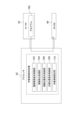
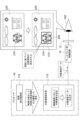
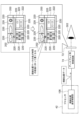
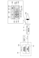
- FIG. 10 is an explanatory diagram showing an example of a method of detecting a line-of-sight position
- 3 is a block diagram showing an example of a functional configuration of a processor according to the first embodiment
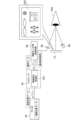
- FIG. 4 is an explanatory diagram showing an example of a first operation of the processor according to the first embodiment
- FIG. 7 is an explanatory diagram showing an example of a second operation of the processor according to the first embodiment
- FIG. 10 is an explanatory diagram showing an example of a third operation of the processor according to the first embodiment;
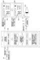
- FIG. 10 is an explanatory diagram showing an example of a method of detecting a line-of-sight position
- 3 is a block diagram showing an example of a functional configuration of a processor according to the first embodiment
- FIG. 4 is an explanatory diagram showing an example of a first operation of the processor according to the first embodiment
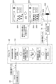
- FIG. 7 is an explanatory diagram showing an example of a second operation of the processor according to the first embodiment
- FIG. 10 is an explanatory
- FIG. 11 is an explanatory diagram showing an example of a fourth operation of the processor according to the first embodiment
- FIG. 14 is an explanatory diagram showing an example of a fifth operation of the processor according to the first embodiment
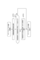
- 6 is a flowchart showing an example of the flow of target area setting processing according to the first embodiment
- FIG. 5 is an explanatory diagram showing a modification of the operation of the processor according to the first embodiment
- FIG. 11 is an explanatory diagram showing an example of the operation of the processor according to the second embodiment
- FIG. 11 is an explanatory diagram showing an example of a first operation of a processor according to the third embodiment
- FIG. 14 is an explanatory diagram showing an example of a second operation of the processor according to the third embodiment
- FIG. 20 is an explanatory diagram showing an example of the first operation of the processor according to the fourth embodiment;
- FIG. 20 is an explanatory diagram showing an example of a second operation of the processor according to the fourth embodiment;
- FIG. 16 is a flowchart showing an example of the flow of target area setting processing according to the fourth embodiment;
- FIG. 20 is an explanatory diagram showing a first modification of the operation of the processor according to the fourth embodiment;
- FIG. 20 is an explanatory diagram showing a second modified example of the operation of the processor according to the fourth embodiment;
- FIG. 22 is an explanatory diagram showing an example of the operation of the processor according to the fifth embodiment;
- FIG. 16 is a flowchart showing an example of the flow of target area setting processing according to the fifth embodiment;
- FIG. 20 is an explanatory diagram showing an example of the first operation of the processor according to the sixth embodiment
- FIG. 22 is an explanatory diagram showing an example of the second operation of the processor according to the sixth embodiment
- FIG. 22 is an explanatory diagram showing an example of a third operation of the processor according to the sixth embodiment
- FIG. 22 is an explanatory diagram showing an example of a fourth operation of the processor according to the sixth embodiment
- FIG. 16 is a flowchart showing an example of the flow of target area setting processing according to the sixth embodiment
- FIG. FIG. 22 is an explanatory diagram showing an example of the first operation of the processor according to the seventh embodiment
- FIG. 22 is an explanatory diagram showing an example of the second operation of the processor according to the seventh embodiment
- FIG. 22 is a flowchart showing an example of the flow of target area setting processing according to the seventh embodiment;
- FIG. 22 is an explanatory diagram showing an example of the operation of the processor according to the eighth embodiment;
- FIG. 16 is a flow chart showing an example of the flow of autofocus processing according to the eighth embodiment;
- FIG. 22 is a flowchart showing an example of the flow of target area setting processing according to the seventh embodiment;
- FIG. 22 is an explanatory diagram showing an example of the operation of the processor according to the eighth embodiment;
- FIG. 16 is a flow chart showing an example of the flow of autofocus processing according to the eighth embodiment;
- I/F is an abbreviation for "Interface”.
- CPU is an abbreviation for "Central Processing Unit”.
- NVM is an abbreviation for "Non-Volatile Memory”.
- RAM is an abbreviation for "Random Access Memory”.
- EEPROM is an abbreviation for "Electrically Erasable and Programmable Read Only Memory”.
- HDD is an abbreviation for "Hard Disk Drive”.
- CMOS is an abbreviation for "Complementary Metal Oxide Semiconductor”.
- CCD is an abbreviation for "Charge Coupled Device”.
- SSD is an abbreviation for "Solid State Drive”.
- EL is an abbreviation for "Electro Luminescence”.
- LED is an abbreviation for "light emitting diode”.
- OLED is an abbreviation for "Organic Light-Emitting Diode".
- GPU is an abbreviation for "Graphics Processing Unit”.
- TPU is an abbreviation for "Tensor processing unit”.
- USB is an abbreviation for "Universal Serial Bus”.
- ASIC is an abbreviation for "Application Specific Integrated Circuit”.
- FPGA is an abbreviation for "Field-Programmable Gate Array”.
- PLD is an abbreviation for "Programmable Logic Device”.
- SoC is an abbreviation for "System-on-a-chip.”
- IC is an abbreviation for "Integrated Circuit”.
- the imaging device 10 is a digital camera and includes a lens unit 12 and an imaging device main body 14 .
- the imaging device 10 is an example of an “information processing device” and an “imaging device” according to the technology of the present disclosure.
- the imaging device 10 has a pitch axis, a yaw axis, and a roll axis.
- the axis P indicates the pitch axis of the imaging device 10
- the axis Y indicates the yaw axis of the imaging device 10
- the axis R indicates the roll axis of the imaging device 10 .
- the lens unit 12 is attached to the imaging device body 14 .
- a touch panel display 34 and instruction keys 36 are provided on the rear surface of the imaging device body 14 .
- the touch panel display 34 is formed by a touch panel 34A and a display 34B. For example, the touch panel 34A is superimposed on the display 34B.
- An electronic viewfinder 28 is provided on the top of the imaging device body 14 .
- the electronic viewfinder 28 has a display 72 .
- a finder opening 16 is provided in the upper portion of the imaging device main body 14 , and the display 72 is provided inside the finder opening 16 .
- the display 72 is positioned so that the user can see the display 72 with his/her eyes 302 when looking through the viewfinder opening 16 .
- the display 72 is an example of a "display" according to the technology of the present disclosure.
- a light source 82 for line-of-sight detection and a line-of-sight sensor 86 are provided inside the viewfinder opening 16 .
- a user's eye 302 looking into the viewfinder opening 16 is a line-of-sight detection target.
- Light source 82 has a plurality of light emitters 82A. The plurality of light emitters 82A are arranged side by side in the pitch axis direction of the imaging device 10, for example.
- the light source 82 is arranged at a position where the user's eyes 302 can be illuminated with light when the user looks into the viewfinder opening 16 .
- the light source 82 emits near-infrared light, for example.
- the line-of-sight sensor 86 is arranged at a position where the user's eyes 302 can be imaged when the user looks into the viewfinder opening 16 .
- a half mirror (not shown) may be arranged inside the viewfinder opening 16 .
- the display 72 may be arranged on the passing optical axis of the half mirror, and the line-of-sight sensor 86 may be arranged on the reflecting optical axis of the half mirror.
- the imaging device body 14 includes a computer 20, an image sensor 24, an image sensor control circuit 26, an electronic viewfinder 28, a line-of-sight detection unit 30, an image memory 32, a UI device 92, and an input device.
- An output I/F 38 is provided.
- the image sensor 24 , the image sensor control circuit 26 , the image memory 32 and the UI device 92 are connected to the input/output I/F 38 .
- the computer 20 comprises a processor 42, NVM 44, and RAM 46.
- the processor 42 controls the imaging device 10 as a whole.
- the processor 42 is, for example, a processing device that includes a CPU and a GPU.
- the GPU operates under the control of the CPU and is responsible for executing image processing.
- a processing device including a CPU and a GPU is mentioned here as an example of the processor 42, this is only an example, and the processor 42 may be one or more CPUs with integrated GPU functions, It may be one or more CPUs that do not integrate GPU functionality.
- Processor 42 , NVM 44 , and RAM 46 are connected via bus 48 , and bus 48 is connected to input/output I/F 38 .
- the computer 20 is an example of a "computer” according to the technology of the present disclosure.
- the processor 42 is an example of a "processor” according to the technology of the present disclosure.
- the NVM 44 is a non-temporary storage medium and stores various parameters and various programs.
- NVM 44 is flash memory (eg, EEPROM).
- flash memory eg, EEPROM
- HDD high-density diode
- the RAM 46 temporarily stores various information and is used as a work memory.
- the processor 42 reads necessary programs from the NVM 44 and executes the read programs in the RAM 46 .
- the processor 42 controls the image sensor 24 , the image sensor control circuit 26 , the electronic viewfinder 28 , the line-of-sight detection unit 30 , the image memory 32 , and the UI device 92 according to programs executed in the RAM 46 .
- the image sensor 24 is, for example, a CMOS image sensor.
- a CMOS image sensor is exemplified as the image sensor 24, but the technology of the present disclosure is not limited to this.
- the image sensor 24 may be another type of image sensor such as a CCD image sensor. technology is established.
- An image sensor control circuit 26 is connected to the image sensor 24 .
- the image sensor control circuit 26 controls the image sensor 24 according to the imaging control signal from the processor 42 .
- Subject light enters the imaging lens 52 of the lens unit 12, which will be described later.
- Subject light is imaged on the light receiving surface of the image sensor 24 by the imaging lens 52 .
- a photoelectric conversion element (not shown) is provided on the light receiving surface of the image sensor 24 .
- the photoelectric conversion element photoelectrically converts subject light received by the light-receiving surface, and outputs an electrical signal corresponding to the amount of subject light as analog image data representing the subject light. do.
- the image sensor 24 has a signal processing circuit (not shown).
- the signal processing circuit digitizes analog image data to generate digital captured image data and outputs the captured image data.
- the captured image data generated by the image sensor 24 is temporarily stored in the image memory 32 .
- the processor 42 acquires captured image data from the image memory 32 and executes various processes using the acquired captured image data.
- the lens unit 12 has an imaging lens 52 .
- the imaging lens 52 has an objective lens 54, a focus lens 56, a zoom lens 58, and an aperture 60, for example.
- the lens unit 12 also includes a lens control circuit 62 , a first actuator 64 , a second actuator 66 and a third actuator 68 .
- a lens control circuit 62 is connected to the first actuator 64 , the second actuator 66 , and the third actuator 68 , and the lens control circuit 62 is connected to the input/output I/F 38 .
- the lens control circuit 62 controls the first actuator 64 , the second actuator 66 and the third actuator 68 according to the lens control signal from the processor 42 .
- the first actuator 64 moves the focus lens 56 along the optical axis OA.
- the focus position is adjusted by changing the position of the focus lens 56 .
- a second actuator 66 moves the zoom lens 58 along the optical axis OA.
- the focal length is adjusted by changing the position of the zoom lens 58 .
- a third actuator 68 changes the size of the aperture of the diaphragm 60 . By changing the size of the aperture of the diaphragm 60, the aperture amount of the diaphragm 60 is changed, thereby adjusting the exposure.
- the first actuator 64, the second actuator 66, and the third actuator 68 are, for example, piezoelectric elements or voice coil motors.
- the electronic viewfinder 28 has a display 72 , a display control circuit 74 and an eyepiece 76 .
- the display 72 is, for example, a liquid crystal display or an EL display.
- the display control circuit 74 is connected to the input/output I/F 38 .
- the processor 42 selectively outputs captured image data, line-of-sight position data, gaze position data, and target area data to the display control circuit 74, as will be described later.
- the display control circuit 74 displays an image on the display 72 according to the imaged image data, line-of-sight position data, gaze position data, and target area data.
- the eyepiece lens 76 is arranged to face the screen of the display 72 .
- the line-of-sight detection unit 30 has a light source 82 , a light source control circuit 84 , a line-of-sight sensor 86 , and a line-of-sight sensor control circuit 88 .
- the light source 82 is, for example, an LED that outputs near-infrared light.
- the light source control circuit 84 is connected to the input/output I/F 38 .
- the light source control circuit 84 controls the light source 82 according to the light source control signal from the processor 42 .
- the line-of-sight sensor 86 is, for example, a CMOS image sensor sensitive to near-infrared light.
- a CMOS image sensor is exemplified as the line-of-sight sensor 86, but the technology of the present disclosure is not limited to this. technology is established.
- a line-of-sight sensor control circuit 88 is connected to the line-of-sight sensor 86 .
- the line-of-sight sensor control circuit 88 controls the line-of-sight sensor 86 according to the imaging control signal from the processor 42 .
- the line-of-sight sensor 86 captures an image of a subject (eg, the user's eye 302) and outputs line-of-sight data obtained by capturing the image.
- the UI device 92 has a display 34B.
- the processor 42 outputs display image data to the display 34B, and causes the display 34B to display an image and various information based on the display image data.
- the UI-based device 92 also includes a reception device 94 that receives instructions from the user.
- the reception device 94 has a touch panel 34A and a hard key section 96 .
- the hard key portion 96 is a plurality of hard keys including the instruction key 36 (see FIG. 1).
- the reception device 94 outputs reception data corresponding to various instructions received by the touch panel 34A and/or the hard key portion 96 .
- FIG. 3 shows an example of a method for detecting the line-of-sight position based on the line-of-sight data.
- near-infrared light is emitted from a plurality of light emitters 82A to the eyeball 306, and the near-infrared light is reflected on the surface of the cornea 308, thereby forming a dotted pattern 234 on the surface of the cornea 308.
- a distance L1 between the patterns 234 is obtained from an image 238 obtained by capturing an image of the eyeball 306 with the line-of-sight sensor 86 .
- the distance between the line-of-sight sensor 86 and the eyeball 306 is calculated. is obtained.
- the positions of the center 310A of the pupil 310 and the outer shape 310B of the pupil 310 with respect to the center 238A of the image 238 are obtained from the image 238 obtained by capturing the image of the eyeball 306 with the line-of-sight sensor 86 .
- the eyeball Based on the positions of the center 310A of the pupil 310 and the outline 310B of the pupil 310 relative to the center 238A of the image 238, the distance L3 between the line-of-sight sensor 86 and the eyeball 306, and the preset radius of curvature for the eyeball 306, the eyeball
- the coordinates of the center 306A of the pupil 306 and the coordinates of the center 310A of the pupil 310 are determined. For example, a statistically determined numerical value is applied to the radius of curvature of the eyeball 306 .
- the direction in which the line 312 connecting the coordinates of the center 306A of the eyeball 306 and the coordinates of the center 310A of the pupil 310 extends corresponds to the direction of the line of sight of the eye 302.
- An extension line 314 obtained by extending the line 312 connecting the coordinates of the center 306A of the eyeball 306 and the coordinates of the center 310A of the pupil 310 indicates the line of sight of the eye 302, and the line of sight of the eye 302 and the screen of the display 72 intersect.
- a point P corresponding to the position of the line of sight of the eye 302 .
- the line-of-sight position of the eye 302 is detected based on the line-of-sight data obtained by imaging the eyeball 306 with the line-of-sight sensor 86 .
- the “line-of-sight position of the eye 302” is also referred to as the “line-of-sight position” or the “line-of-sight position with respect to the display 72”.
- the line-of-sight position is an example of the "line-of-sight position" according to the technology of the present disclosure.
- the method of detecting the line-of-sight position described above is merely an example, and the technology of the present disclosure is not limited to this.
- the line-of-sight to the display 72 can be detected based on the line-of-sight data obtained by imaging the eyeball 306 with the line-of-sight sensor 86 while the pattern 234 is formed on the surface of the cornea 308 .
- Various methods of position detection are applicable to the technology of the present disclosure.
- the line-of-sight position is detected based on the reflected light reflected by the surface of the cornea 308. , the line-of-sight position may be detected.
- the NVM 44 of the imaging device 10 stores a program 100 .
- the program 100 is an example of a "program" according to the technology of the present disclosure.
- Processor 42 reads program 100 from NVM 44 and executes read program 100 in RAM 46 .
- the processor 42 performs target area setting processing according to the program 100 executed by the RAM 46 .
- the processor 42 operates according to the program 100 as the captured image display control unit 102, the line-of-sight detection processing unit 104, the line-of-sight position display control unit 106, the gaze position display control unit 108, and the target region setting unit 110. is executed in
- the imaging device 10 has a plurality of operation modes and operates under designated operation modes.
- the target area setting process is executed, for example, when the target area setting mode is set as the operation mode of the imaging device 10 .
- the target area setting mode is set for the imaging device 10, for example, when an instruction to set the target area setting mode is received by the receiving device 94 (see FIG. 2).
- the target area setting mode setting instruction refers to, for example, an instruction to shift from an operation mode other than the target area setting mode to the target area setting mode.
- the captured image display control unit 102 causes the display 72 to display the captured image 200 .
- the captured image display control unit 102 performs the following processing. That is, the captured image display control unit 102 outputs an image capturing control signal to the image sensor control circuit 26 to capture an object (not shown) to the image sensor 24 via the image sensor control circuit 26 .
- the captured image display control unit 102 acquires captured image data obtained by capturing an image of the subject by the image sensor 24 and outputs the acquired captured image data to the display 72 .
- the display 72 displays the captured image 200 indicated by the captured image data. As a result, the captured image 200 including the subject as an image is displayed on the display 72 .
- Captured image data is an example of "first image data" according to the technology of the present disclosure.
- the captured image 200 is an example of a “first image” according to the technology of the present disclosure.
- the line-of-sight detection processing unit 104 detects the line-of-sight position of the user viewing the display 72 on which the captured image 200 is displayed. Specifically, the line-of-sight detection processing unit 104 performs the following processing. That is, the line-of-sight detection processing unit 104 outputs an imaging control signal to the line-of-sight sensor control circuit 88, thereby causing the line-of-sight sensor 86 to detect the subject (eg, the user's eyes) via the line-of-sight sensor control circuit 88. 302) is imaged.
- the line-of-sight detection processing unit 104 outputs an imaging control signal to the line-of-sight sensor control circuit 88, thereby causing the line-of-sight sensor 86 to detect the subject (eg, the user's eyes) via the line-of-sight sensor control circuit 88. 302) is imaged.
- the line-of-sight detection processing unit 104 acquires line-of-sight data obtained by imaging by the line-of-sight sensor 86, and detects the line-of-sight position with respect to the display 72 based on the acquired line-of-sight data.
- the method for detecting the line-of-sight position is as described with reference to FIG. Thereby, the line-of-sight position of the user viewing the display 72 on which the captured image 200 is displayed is detected.
- Line-of-sight data is an example of "line-of-sight data" according to the technology of the present disclosure.
- the line-of-sight detection processing unit 104 When the line-of-sight position is detected, the line-of-sight detection processing unit 104 generates line-of-sight position data indicating the line-of-sight position, and stores the line-of-sight position data in the RAM 46 .
- the light source 82 may continue to emit near-infrared light when the imaging device 10 is powered on. Further, the light source 82 emits near-infrared light when the line-of-sight position is detected by the line-of-sight detection processing unit 104, and emits near-infrared light when the line-of-sight position is not detected by the line-of-sight detection processing unit 104. may be stopped.
- the line-of-sight position display control unit 106 causes the display 72 to display a line-of-sight position mark 202 corresponding to the line-of-sight position. Specifically, the line-of-sight position display control unit 106 performs the following processing. That is, the line-of-sight position display control unit 106 acquires all the line-of-sight position data stored in the RAM 46 after the target area setting process was started. Based on the acquired line-of-sight position data, the line-of-sight position display control unit 106 then determines whether or not the change distance of the line-of-sight position is equal to or less than a predetermined distance.
- the change distance may be, for example, the total distance that the line-of-sight position has moved, but it is a distance that indicates the radius or diameter of the range in which the line-of-sight position has moved based on the first detected line-of-sight position.
- the change distance of the line-of-sight position is calculated by, for example, the average value or the maximum value of the change distance of the line-of-sight position indicated by all the line-of-sight position data stored in the RAM 46 .
- the default distance is set, for example, to a distance at which it is recognized that the line-of-sight position is being gazed at.
- the predetermined distance is an example of the "first distance" according to the technology of the present disclosure.
- the line-of-sight position display control unit 106 determines that the line-of-sight position variation distance is equal to or less than the predetermined distance, the line-of-sight position display control unit 106 outputs the line-of-sight position data including the line-of-sight position mark 202, which is a mark indicating the line-of-sight position, on the captured image 200 to the display 72. .
- the line-of-sight position indicated by the line-of-sight position mark 202 is set based on, for example, the average value of the line-of-sight positions indicated by all the line-of-sight position data stored in the RAM 46 .
- the display 72 superimposes and displays the line-of-sight position mark 202 indicated by the line-of-sight position data on the captured image 200 .
- the line-of-sight position mark 202 corresponding to the line-of-sight position is displayed on the display 72 .
- the line-of-sight position display control unit 106 determines whether or not the change distance of the line-of-sight position has continued for a predetermined time period or longer.
- the predetermined time is set, for example, to the time allowed for gazing at the line-of-sight position.
- the predetermined time is an example of the "first time” according to the technology of the present disclosure. If the line-of-sight position display control unit 106 determines that the line-of-sight position variation distance is equal to or less than the predetermined distance and has not continued for a predetermined period of time or longer, the process of acquiring the captured image data described above (see FIG. 5), the above-described line-of-sight The process of acquiring data (see FIG.
- line-of-sight position data is repeatedly output to the display 72 when the change distance of the line-of-sight position has not continued for a predetermined time or longer.
- line-of-sight position data indicating the line-of-sight position mark 202 specifying the line-of-sight position in the captured image 200 is output to the display 72 until the predetermined time is reached.
- the line-of-sight position data is an example of "data indicating a line-of-sight position mark" according to the technology of the present disclosure.
- the line-of-sight position mark 202 is an example of the “line-of-sight position mark” according to the technology of the present disclosure.
- the line-of-sight position display control unit 106 When repeatedly outputting the line-of-sight position data to the display 72, the line-of-sight position display control unit 106 changes the form of the line-of-sight position mark 202 over time. For example, the line-of-sight position display control unit 106 performs a process of darkening the color of the line-of-sight position mark 202 over time. Note that the line-of-sight position display control unit 106 may, for example, perform a process of darkening aspects other than color, such as the shape of the line-of-sight position mark 202, over time.
- gaze position display control unit 106 determines that the change distance of the gaze position has continued for a predetermined time or longer, the captured image 200 is displayed.
- the gaze position is detected as the gaze position when the change distance of the gaze position with respect to the object continues for a predetermined time or longer.
- gaze position display control section 108 outputs gaze position data including gaze position mark 204 , which is a mark indicating the gaze position, on captured image 200 to display 72 .
- gaze position data indicating the gaze position mark 204 specifying the gaze position in the captured image 200 is output to the display 72 .
- the display 72 superimposes the gaze position mark 204 indicated by the gaze position data on the captured image 200 instead of the gaze position mark 202 and displays it.
- the gaze position mark 204 is preferably different from the gaze position mark 202 in order to indicate that the gaze position has been detected from the gaze position.
- the gaze position mark 204 is displayed in a darker color than the line-of-sight position mark 202 .
- the gaze position is an example of the "gazing position" according to the technology of the present disclosure.
- the gaze position data is an example of "data indicating a gaze position mark” according to the technology of the present disclosure.
- the gaze position mark 204 is an example of the "gaze position mark” according to the technology of the present disclosure.
- the gaze position display control unit 108 After outputting the gaze position data to the display 72, the gaze position display control unit 108 deletes the gaze position data stored in the RAM 46. Further, when the gaze position is detected, the gaze position display control unit 108 generates gaze position data indicating the gaze position, and stores the gaze position data in the RAM 46 . A plurality of pieces of gaze position data are stored in the RAM by repeatedly executing the processing from acquiring the above-described captured image data to storing the gaze position data in the RAM 46 .
- the target region setting unit 110 sets a target region 206 for the captured image 200 based on a plurality of gaze positions. Specifically, the target area setting unit 110 performs the following processing. That is, the target area setting unit 110 acquires all gaze position data stored in the RAM 46 after the start of the target area setting process. Subsequently, the target region setting unit 110 determines whether or not the number of detected gaze positions has reached a predetermined number based on the acquired gaze position data. The number of gaze positions detected corresponds to the number of gaze position data stored in the RAM 46 . The predetermined number is set to a number that allows the target region 206 to be set for the captured image 200 based on the gaze position. In the first embodiment, the default number is set to 2 as an example.
- the target area setting unit 110 determines that the number of detected gaze positions has not reached the predetermined number
- the above-described processing from acquiring the captured image data to outputting the gaze position data is executed again.
- two gaze positions are detected by repeatedly executing the process from acquiring the above-described captured image data to outputting gaze position data, and two gaze position marks 204 are displayed on the display 72. Displayed states are shown.
- the target region setting unit 110 determines that the number of detected gaze positions has reached the predetermined number, the target region setting unit 110 sets the target region 206 in the captured image 200 based on the detected gaze positions.
- the target area setting unit 110 sets, for example, a rectangular area diagonal to the gaze positions indicated by the two gaze position marks 204 as the target area 206 for the captured image 200 . In this manner, the target area 206 is set for the captured image 200 based on a plurality of gaze positions.
- the target area setting unit 110 outputs target area data including the target area frame 208 indicating the target area 206 in the captured image 200 to the display 72 .
- the display 72 displays a target area frame 208 indicated by the target area data so as to be superimposed on the captured image 200 and the gaze position mark 204 .
- the target area 206 is an example of a "first area" according to the technology of the present disclosure.
- the target area 206 set in the manner described above is used, for example, for adjustment of exposure by automatic exposure and/or adjustment of image quality by automatic white balance.
- the target area setting process may be executed from the beginning when, for example, an instruction to erase the gaze position is received by the receiving device 94 (see FIG. 2) in the process of setting the above-described area. This makes it possible to redo the setting of the gaze position when the gaze position is set at an undesired position by the user.
- the default number is set to 2 as an example, but the default number may be set to 3 or more. That is, the number of gaze positions detected may be three or more.
- FIG. 10 shows an example of the flow of target area setting processing according to the first embodiment.
- step ST10 the captured image display control section 102 causes the image sensor 24 to capture an image of the subject. Then, the captured image display control unit 102 acquires captured image data obtained by capturing an image of the subject by the image sensor 24 . After the process of step ST10 is executed, the target area setting process proceeds to step ST11.
- step ST11 the captured image display control unit 102 outputs the captured image data acquired at step ST10 to the display 72. Thereby, the captured image 200 is displayed on the display 72 .
- step ST12 the target area setting process proceeds to step ST12.
- step ST12 the line-of-sight detection processing unit 104 acquires line-of-sight data captured by the line-of-sight sensor 86. After the process of step ST12 is executed, the target area setting process proceeds to step ST13.
- step ST13 the line-of-sight detection processing unit 104 detects the line-of-sight position with respect to the display 72 based on the line-of-sight data acquired at step ST12. After the process of step ST13 is executed, the target area setting process proceeds to step ST14.
- step ST14 the line-of-sight detection processing unit 104 generates line-of-sight position data indicating the line-of-sight position detected in step ST13, and stores the line-of-sight position data in the RAM46.
- step ST14 the target area setting process proceeds to step ST15.
- step ST15 the line-of-sight position display control unit 106 acquires all the line-of-sight position data stored in the RAM 46 after the target area setting process is started, and based on the acquired line-of-sight position data, the change distance of the line-of-sight position is calculated. Determine whether or not the distance is less than or equal to the predetermined distance. In step ST15, if the change distance of the line-of-sight position is not equal to or less than the predetermined distance, the determination is negative, and the target area setting process proceeds to step ST10. In step ST15, when the change distance of the line-of-sight position is equal to or less than the predetermined distance, the determination is affirmative, and the target area setting process proceeds to step ST16.
- step ST16 the line-of-sight position display control unit 106 outputs line-of-sight position data including the line-of-sight position mark 202 indicating the line-of-sight position to the display 72.
- the line-of-sight position mark 202 indicated by the line-of-sight position data is superimposed on the captured image 200 and displayed on the display 72 .
- step ST17 the line-of-sight position display control unit 106 determines whether or not the change distance of the line-of-sight position has continued for a predetermined time period or longer. In step ST17, if the line-of-sight position variation distance has not continued for a predetermined time or longer, the determination is negative, and the target area setting process proceeds to step ST10. In step ST17, if the change distance of the line-of-sight position has continued for a predetermined time or longer, the determination is affirmative, and the target area setting process proceeds to step ST18.
- step ST18 the gaze position display control unit 108 detects the gaze position as the gaze position, and outputs gaze position data including the gaze position mark 204 indicating the detected gaze position to the display 72.
- the gaze position mark 204 indicated by the gaze position data is superimposed on the captured image 200 and displayed on the display 72 .
- step ST19 the gaze position display control unit 108 erases the line-of-sight position data stored in the RAM46. After the process of step ST19 is executed, the target area setting process proceeds to step ST20.
- step ST20 the gaze position display control unit 108 generates gaze position data indicating the gaze position detected in step ST18, and stores the gaze position data in the RAM46. After the process of step ST20 is executed, the target area setting process proceeds to step ST21.
- step ST21 the target area setting unit 110 acquires all gaze position data stored in the RAM 46 after the target area setting process was started, and based on the acquired gaze position data, the number of detected gaze positions determines whether or not has reached a predetermined number. In step ST21, if the number of detected gaze positions has not reached the predetermined number, the determination is negative, and the target area setting process proceeds to step ST10. In step ST21, when the number of detected gaze positions reaches the predetermined number, the determination is affirmative, and the target area setting process proceeds to step ST22.
- step ST22 the target area setting unit 110 sets the target area 206 for the captured image 200 based on the multiple gaze positions indicated by the multiple gaze position data stored in the RAM in step ST20. After the process of step ST22 is executed, the target area setting process proceeds to step ST23.
- the target area setting section 110 outputs to the display 72 target area data including the target area frame 208 indicating the target area 206 set at step ST22.
- the target area frame 208 indicated by the target area data is displayed on the display 72 while being superimposed on the captured image 200 and the gaze position mark 204 .
- the target area setting process ends.
- the information processing method described as the action of the imaging device described above is an example of the “information processing method” according to the technology of the present disclosure.
- the processor 42 acquires captured image data and outputs the captured image data to the display 72 .
- the processor 42 acquires the line-of-sight data, and based on the line-of-sight data, gazes at the line-of-sight position when the change distance of the line-of-sight position with respect to the captured image 200 indicated by the captured image data is equal to or less than a predetermined distance for a predetermined time or longer. Detect as a position.
- Processor 42 then establishes region of interest 206 based on the two or more gaze positions. Therefore, the target area 206 can be set for the captured image 200 based on the line-of-sight position.
- the processor 42 sets a rectangular area having two gazing positions as diagonals as the target area 206 . Therefore, the target area 206, which is a rectangular area, can be set for the captured image 200 based on the two line-of-sight positions.
- the processor 42 outputs line-of-sight position data indicating the line-of-sight position mark 202 for specifying the line-of-sight position within the captured image 200 until the predetermined time is reached, and when the predetermined time is reached, the line-of-sight position within the captured image 200 is output. Gaze position data indicating the specified gaze position mark 204 is output. Therefore, by gazing at the captured image 200 until the predetermined time is reached, the gaze position mark 204 can be displayed at the gazed position.
- the line-of-sight position mark 202 changes in appearance over time. Therefore, for example, it is possible to make the user recognize that the captured image 200 is being watched, as compared with the case where the line-of-sight position mark 202 has a constant aspect.
- the target region setting unit 110 when setting a target region 206 based on a gaze position, sets a circular region whose diameter is a line connecting two gaze positions in the captured image 200. may be set as the region of interest 206 for
- the area set based on two or more gaze positions may have any shape.
- FIG. 12 shows the second embodiment.
- the following changes are made with respect to the first embodiment.
- the second embodiment will be described below based on an example in which four gaze positions are detected.
- the plurality of gaze position marks 204 are designated as gaze position mark 204A, gaze position mark 204B, and gaze position mark 204C. , and gaze position mark 204D.
- the gaze position corresponding to each gaze position mark 204 is detected in order of gaze position mark 204A, gaze position mark 204B, gaze position mark 204C, and gaze position mark 204D.
- the default number for setting target regions 206 based on gaze positions is set to four.
- the target region setting unit 110 acquires all gaze position data stored in the RAM 46 after the target region setting process is started, and based on the acquired gaze position data, sets the number of detected gaze positions to a predetermined number. Determine whether or not it has been reached.
- the target region setting unit 110 determines that the number of detected gaze positions has reached the predetermined number
- the target region setting unit 110 sets the target region 206 for the captured image 200 .
- the target region setting unit 110 sets, for example, a closed region determined by connecting the four gaze positions indicated by the four gaze position marks 204 in the detected order as the target region 206 for the captured image 200 .
- the target area setting unit 110 outputs target area data including the target area frame 208 , which is a mark indicating the target area 206 in the captured image 200 , to the display 72 .
- the display 72 displays a target area frame 208 indicated by the target area data so as to be superimposed on the captured image 200 and the gaze position mark 204 .
- the processor 42 sets, as the target area 206 for the captured image 200, a closed area determined by connecting the four gaze positions in the order in which they are detected. Therefore, the target area 206, which is a closed area, can be set for the captured image 200 based on the four line-of-sight positions.
- the target region 206 may be set based on three gaze positions, or may be set based on five or more gaze positions.
- FIG. 13 shows the third embodiment.
- the gaze position is called gaze position 210 .
- the third embodiment will be described below based on an example in which five gaze positions 210 are detected.
- the plurality of gaze positions 210 are referred to as gaze position 210A, gaze position 210B, gaze position 210C, gaze position 210D, and gaze position 210E.
- the gaze position 210 is detected in order of gaze position 210A, gaze position 210B, gaze position 210C, gaze position 210D, and gaze position 210E.
- the target region setting unit 110 acquires all the gaze position data stored in the RAM 46 after the target region setting process is started, and sets the target region 206 (Fig. 14) can be set. For example, when the target region setting unit 110 detects three or more gaze positions 210 as in the example shown in FIG. If the intersection position 214 is set at the position where the line 212B connecting 210E intersects, the target area 206 can be set based on the gaze position 210B, the gaze position 210C, the gaze position 210D, and the intersection position 214. It is determined that the target area 206 can be set based on the plurality of gaze positions 210 . Then, when the target region setting unit 110 determines that the target region 206 can be set based on the plurality of gaze positions 210, the position where the lines 212A and 212B connecting the two gaze positions 210 intersect is set as the intersection position. 214.
- the target region setting unit 110 sets the target region 206 based on the gaze position 210B, the gaze position 210C, the gaze position 210D, and the intersection position 214 that exist at positions where the target region 206 can be defined.
- a region 206 is set. That is, a closed area determined by connecting the gaze position 210B, the gaze position 210C, the gaze position 210D, and the intersection position 214 is set as the target area 206 for the captured image 200.
- FIG. thus, at least 4+1 fixation positions 210 are used when setting a region of interest 206 having four vertices.
- the target area setting unit 110 outputs target area data including the target area frame 208 which is a mark indicating the target area 206 in the captured image 200 to the display 72 .
- the target region setting unit 110 also provides gaze position data including a gaze position mark 204, which is a mark indicating a gaze position 210 defining a target region 206 in the captured image 200, and a mark indicating an intersecting position 214 in the captured image 200.
- Intersection data including intersection mark 216 is output to display 72 .
- the display 72 superimposes and displays a gaze position mark 204, an intersection position mark 216, and a target area frame 208 on the captured image 200 based on the gaze position data, the intersection position data, and the area data.
- the gaze position marks 204 displayed on the display 72 corresponding to the five gaze positions 210 instead of the plurality of gaze position marks 204 displayed on the display 72 corresponding to the five gaze positions 210, the gaze position marks 204 defining the target area 206, the intersection position mark 216, and the target area frame 208 are displayed. is displayed.
- the processor 42 sets the position where the lines 212A and 21B connecting the two gaze positions 210 intersect as the intersection position 214, and the target region 206 A target region 206 is set based on a gaze position 210 and an intersection position 214 that exist at positions that can define . Therefore, even if lines 212A and 212B connecting two gaze positions 210 are generated in the process of setting the target region 206, the target region 206, which is a closed region, can be set.
- the target area 206 is set based on the five gaze positions 210, but may be set based on the four gaze positions 210.
- FIG. In this case, a triangular region of interest 206 is set.
- at least 3+1 fixation positions 210 are used when setting a region of interest 206 having three vertices.
- the region of interest 206 may have a shape with n vertices. n is a natural number. At least 4+1 fixation positions 210 are used when setting a region of interest 206 having n vertices.
- the CPU operates as the trajectory display control section 112 .
- the trajectory display control unit 112 causes the display 72 to display a trajectory line 218 corresponding to the line-of-sight position.
- the trajectory display control unit 112 performs the following processing. That is, the trajectory display control unit 112 acquires all line-of-sight position data stored in the RAM 46 after the target area setting process was started. Subsequently, the line-of-sight position display control unit 106 detects a trajectory determined by connecting the plurality of line-of-sight positions in the order in which the line-of-sight positions are detected, based on the plurality of acquired line-of-sight position data.
- the line-of-sight position display control unit 106 outputs the trajectory data including the trajectory line 218 indicating the trajectory to the display 72 .
- the display 72 superimposes the trajectory line 218 indicated by the trajectory data on the captured image 200 and displays it.
- the trace line 218 corresponding to the line-of-sight position is displayed on the display 72 .
- a trajectory is an example of a 'trajectory' according to the technology of the present disclosure.
- the trajectory display control unit 112 determines whether or not the state in which the trajectory has been detected has continued for a predetermined time or longer.
- the predetermined time may be, for example, the time from when the receiving device 94 (see FIG. 2) starts receiving an instruction from the user until it ends. Further, the predetermined time may be the time from when the acceptance of the instruction from the user is started until the predetermined time (for example, the time when the trajectory for setting the area can be secured) elapses. It may be the time from when the user starts to look at 72 until when the user looks away from the display 72 .
- the predetermined time is an example of the "second time" according to the technology of the present disclosure.
- the trajectory display control unit 112 determines that the state in which the trajectory has been detected has not continued for a predetermined time or longer, the trajectory display control unit 112 performs the process of acquiring the captured image data (see FIG. 5) and the process of acquiring the line-of-sight data (see FIG. 5). 6), and the process of outputting the locus data described above are executed again.
- the locus data is repeatedly output to the display 72 when the state in which the locus has been detected does not continue for a predetermined time or longer.
- the trajectory along which the line-of-sight position has changed is detected until the predetermined time is reached, and trajectory data including a trajectory line 218 that is a line indicating the detected trajectory is output to the display 72 .
- captured image data is an example of "second image data" according to the technology of the present disclosure.
- a captured image 200 indicated by captured image data is an example of a “second image” according to the technology of the present disclosure.
- the target region setting unit 110 sets a target region 206 for the captured image 200 based on the detected trajectory. Specifically, the target area setting unit 110 performs the following processing. That is, when the trajectory display control unit 112 determines that the state in which the trajectory has been detected has continued for a predetermined time or longer, the target region setting unit 110 sets the closed region surrounding the trajectory indicated by the trajectory line 218 to the target region 206 of the captured image 200 . set as In this case, the target region setting unit 110 may set a closed region circumscribing the trajectory as the target region 206 for the captured image 200, or set a closed region away from the trajectory and surrounding the trajectory as the target region 206 for the captured image 200. May be set. In this manner, the target area 206 is set for the captured image 200 based on the trajectory.
- the target area 206 is an example of a "second area" according to the technology of the present disclosure.
- the target area setting unit 110 outputs target area data including the target area frame 208 which is a mark indicating the target area 206 in the captured image 200 to the display 72 .
- the display 72 displays the target area frame 208 indicated by the target area data so as to be superimposed on the captured image 200 and the trajectory line 218 .
- FIG. 17 shows an example of the flow of target area setting processing according to the fourth embodiment.
- step ST30 to step ST34 is the same as the process from step ST10 to step ST14 (see FIG. 10) in the target area setting process according to the first embodiment.
- the target area setting process shown in FIG. 17 proceeds to step ST35 after the process of step ST34 is executed.
- step ST35 the trajectory display control unit 112 acquires all the line-of-sight position data stored in the RAM 46 after the target area setting process is started, and calculates a plurality of line-of-sight positions based on the plurality of acquired line-of-sight position data. A trajectory determined by connecting multiple line-of-sight positions in the order of detection is detected. Then, the line-of-sight position display control unit 106 outputs to the display 72 trajectory data including a trajectory line 218 that is a mark indicating the trajectory. Thereby, the trajectory line 218 indicated by the trajectory data is superimposed on the captured image 200 and displayed on the display 72 .
- step ST36 the trajectory display control unit 112 determines whether or not the state in which the trajectory has been detected has continued for a predetermined time or longer. In step ST36, if the state in which the trajectory has been detected has not continued for the predetermined time or longer, the determination is negative, and the target area setting process proceeds to step ST30. In step ST36, if the state in which the trajectory has been detected continues for the predetermined time or longer, the determination is affirmative, and the target area setting process proceeds to step ST37.
- step ST37 the target area setting unit 110 sets a closed area surrounding the trajectory detected at step ST35 as the target area 206 for the captured image 200. After the process of step ST37 is executed, the target area setting process proceeds to step ST38.
- the target area setting section 110 outputs to the display 72 target area data including the target area frame 208 indicating the target area 206 set at step ST37.
- the target area frame 208 indicated by the target area data is superimposed on the captured image 200 and displayed on the display 72 .
- the target area setting process ends.
- the information processing method described as the action of the imaging device described above is an example of the “information processing method” according to the technology of the present disclosure.
- the processor 42 acquires captured image data and outputs the captured image data to the display 72 .
- the processor 42 acquires line-of-sight data, and based on the line-of-sight data, detects a trajectory along which the line-of-sight position has changed within a predetermined time with respect to the captured image 200 indicated by the captured image data.
- Processor 42 sets target region 206 based on the trajectory. Therefore, the target area 206 can be set for the captured image 200 based on the trajectory of the line-of-sight position change.
- the processor 42 sets a closed area surrounding the trajectory as the target area 206 for the captured image 200 . Therefore, it is possible to set the target area 206, which is a closed area surrounding the trajectory, based on the trajectory in which the line-of-sight position has changed.
- the target region setting unit 110 may set a closed region (for example, a rectangular region) inscribed in the trajectory indicated by the trajectory line 218 as the target region 206 for the captured image 200. .
- the target region setting unit 110 sets the closed region formed by the trajectory as the target region 206 for the captured image 200. May be set. That is, the area surrounded by the trajectory may be set as the target area 206 for the captured image 200 .
- FIG. 20 shows a fifth embodiment.
- the following changes are made with respect to the fourth embodiment.
- the trajectory display control unit 112 determines whether or not blinking has occurred, and outputs trajectory data generated based on the determination result to the display 72 . Specifically, the trajectory display control unit 112 performs the following processing. That is, the trajectory display control unit 112 determines whether or not blinking occurs during the time period during which the trajectory is being detected, based on the line-of-sight position data stored in the RAM 46 .
- the line-of-sight position data stored in the RAM 46 includes, in addition to the line-of-sight position data obtained when the eye is not blinking (that is, when the eye 302 is open), 302 is closed) is also included.
- the trajectory display control unit 112 detects eye gaze position data acquired while blinking (that is, when the eyes 302 are closed), it determines that a blink has occurred.
- the line-of-sight position data acquired when the user is blinking may include error information indicating that the line-of-sight position was not detected. If the line-of-sight position data obtained from the RAM includes line-of-sight position data including error information, the trajectory display control unit 112 determines that blinking has occurred.
- the trajectory display control unit 112 calculates the first line-of-sight position before the blink and the blink based on the line-of-sight position data acquired before and after the line-of-sight position data in the case of blinking.
- the trajectory is detected by performing linear interpolation connecting the second line-of-sight position after the occurrence of . That is, the trajectory display control unit 112 detects the trajectory based on the line connecting the first line-of-sight position before blinking and the second line-of-sight position after blinking. Then, the trajectory display control unit 112 outputs trajectory data indicating the trajectory to the display 72 .
- the locus data generated based on the result of determining whether or not blinking has occurred is output to the display 72 .
- the display 72 superimposes the trajectory line 218 indicated by the trajectory data on the captured image 200 and displays it.
- a first line-of-sight position mark 202A indicating the first line-of-sight position
- a second line-of-sight position mark 202B indicating the second line-of-sight position
- a line connecting the first line-of-sight position and the second line-of-sight position may be superimposed on the captured image 200 and displayed. If the first line-of-sight position and the second line-of-sight position are so far apart that linear interpolation cannot be performed, the trajectory display control unit 112 may cause the display 72 to display characters or the like indicating an error.
- FIG. 21 shows an example of the flow of target area setting processing according to the fifth embodiment.
- step ST40 to step ST41 is added to the target area setting process (see FIG. 17) according to the fourth embodiment.
- the processing from step ST30 to step ST34 is the same as the target area setting processing according to the fourth embodiment.
- the target area setting process shown in FIG. 17 proceeds to step ST40 after the process of step ST34 is executed.
- the trajectory display control unit 112 determines whether or not blinking occurs during the time period during which the trajectory is being detected, based on the line-of-sight position data acquired at step ST34. In step ST40, if blinking has not occurred during the time period during which the trajectory is being detected, the determination is negative, and the target area setting process proceeds to step ST35. In step ST40, if blinking occurs during the time period during which the trajectory is being detected, the determination is affirmative, and the target area setting process proceeds to step ST41.
- step ST41 when determining that a blink has occurred, the trajectory display control unit 112, based on the line-of-sight position data acquired before and after the line-of-sight position data in the case of blinking, determines the first line of sight before the blink.
- the trajectory is detected by performing linear interpolation connecting the line-of-sight position and the second line-of-sight position after the occurrence of the blink.
- the processing from step ST35 to step ST38 is the same as the target area setting processing according to the fourth embodiment.
- the processor 42 determines whether or not blinking occurs during the time period during which the trajectory is being detected, based on the line-of-sight position data obtained from the line-of-sight data. Then, when the processor 42 determines that the blink has occurred, the processor 42 detects the trajectory based on the line connecting the first line-of-sight position before the blink and the second line-of-sight position after the blink. Therefore, even when blinking occurs, the target area 206 can be set based on the trajectory.
- the captured image display control unit 102 causes the display 72 to display a division grid 222 that divides the captured image 200 into a plurality of areas 220 .
- the captured image display control unit 102 performs the following processing. That is, the captured image display control unit 102 outputs an image capturing control signal to the image sensor control circuit 26 to capture an object (not shown) to the image sensor 24 via the image sensor control circuit 26 .
- the captured image display control unit 102 acquires captured image data obtained by capturing an image of a subject by the image sensor 24 .
- the captured image display control unit 102 divides the captured image 200 into a plurality of areas 220.
- the captured image display control unit 102 may divide the captured image 200 into a plurality of areas 220 in accordance with instructions from the user received by the receiving device 94 (see FIG. 2).
- the captured image 200 may be divided into a plurality of regions 220 based on the result of performing image processing on the .
- the captured image display control unit 102 may divide the captured image 200 into a plurality of regions 220 based on information regarding the depth of field and the like obtained from the captured image data.
- the plurality of regions 220 is an example of the “plurality of regions” according to the technology of the present disclosure.
- the captured image display control unit 102 generates region division data indicating division grids 222 that divide the captured image 200 into a plurality of regions 220 and outputs the captured image data and the region division data to the display 72 .
- the display 72 displays the captured image 200 indicated by the captured image data.
- the captured image 200 in which the subject appears as an image is displayed on the display 72 .
- the display 72 displays the division grid 222 indicated by the area division data by superimposing it on the captured image 200 . In this manner, a division grid 222 that divides the captured image 200 into a plurality of areas 220 is displayed on the display 72 .
- the line-of-sight position display control unit 106 outputs the line-of-sight position data to the display 72 in the same manner as in the first embodiment, thereby displaying the line-of-sight position mark 202 corresponding to the line-of-sight position on the display 72. display.
- the line-of-sight position display control unit 106 changes the form of the line-of-sight position mark 202 over time. For example, the line-of-sight position display control unit 106 darkens the color of the line-of-sight position mark 202 over time.
- the gaze position display control unit 108 detects the gaze position as the gaze position in the same manner as in the first embodiment. Then, the gaze position display control unit 108 superimposes the gaze position mark 204 on the captured image 200 by outputting to the display 72 gaze position data including the gaze position mark 204 that indicates the gaze position on the captured image 200 . to display on the display 72. Then, a plurality of gaze positions are detected by repeatedly executing the process from acquiring the above-described captured image data to detecting the gaze position.
- two gaze positions are detected by repeatedly executing the process from acquiring the above-described captured image data to detecting the gaze position, and two gaze position marks 204 are displayed on the display 72. is shown.
- the target region setting unit 110 sets the target region 206 from the plurality of regions 220 based on the plurality of gaze positions.
- the target region setting unit 110 extracts, from the plurality of regions 220, a region that fits in a rectangular region having two gaze positions indicated by the two gaze position marks 204 as diagonal corners, and converts the extracted region into a captured image. 200 as the region of interest 206 .
- target area setting section 110 outputs target area data including target area frame 208 , which is a frame indicating target area 206 in captured image 200 , to display 72 .
- the display 72 superimposes and displays the target area frame 208 indicated by the target area data on the captured image 200 .
- a region is set from a plurality of regions 220 included in the captured image 200 based on two gaze positions.
- a region may be set from a plurality of regions 220 .
- FIG. 26 shows an example of the flow of target area setting processing according to the sixth embodiment.
- step ST50 is added to the target area setting process according to the first embodiment (see FIG. 10).
- the target area setting process shown in FIG. 27 proceeds to step ST50 after the process of step ST10 is executed.
- step ST50 the captured image display control unit 102 generates area division data indicating division grids 222 that divide the captured image 200 into a plurality of areas 220 .
- step ST50 the target area setting process proceeds to step ST11.
- step ST11 the captured image display control unit 102 outputs the captured image data acquired in step ST10 and the segmented data generated in step ST50 to the display 72.
- the display 72 displays the captured image 200 indicated by the captured image data.
- the display 72 displays a division grid 222 indicated by the area division data, superimposed on the captured image 200 .
- step ST12 the target area setting process proceeds to step ST12.
- the processing from step ST12 to step ST21 is the same as the target area setting processing according to the first embodiment.
- the target area setting unit 110 sets the target area 206 from the plurality of areas 220 based on the plurality of gaze positions indicated by the plurality of gaze position data stored in the RAM at step ST20.
- the target area setting process proceeds to step ST23.
- the process of step ST23 is the same as the target area setting process according to the first embodiment.
- the processor 42 sets the target area 206 from the plurality of areas 220 included in the captured image 200 based on two or more gaze positions. Therefore, the target area 206 can be set for the captured image 200 based on the line-of-sight position.
- the target area setting unit 110 may extract from a plurality of areas 220 an area that fits within a circular area whose diameter is the line connecting the two gaze positions, and set the extracted area 220 as the target area 206.
- the target region setting unit 110 extracts from the plurality of regions 220 a region that fits within a closed region determined by connecting the plurality of gaze positions in the order in which the plurality of gaze positions are detected, and sets the extracted region 220 as the target region 206. You may
- FIGS. A seventh embodiment is shown in FIGS. In the seventh embodiment, the following changes are made to the fourth embodiment.
- the captured image display control unit 102 causes the display 72 to display a division grid 222 that divides the captured image 200 into a plurality of areas 220, as in the sixth embodiment.
- the trajectory display control unit 112 outputs the trajectory data including the trajectory line 218, which is the line indicating the trajectory, to the display 72, thereby superimposing the trajectory line 218 indicated by the trajectory data on the captured image 200. display.
- the target area setting unit 110 sets the target area 206 from the plurality of areas 220 based on the trajectory indicated by the trajectory line 218 .
- the target region setting unit 110 extracts, for example, a region 220 that overlaps the trajectory from the plurality of regions 220 and sets the extracted region 220 as the target region 206 for the captured image 200 .
- target area setting section 110 outputs target area data including target area frame 208 , which is a frame indicating target area 206 in captured image 200 , to display 72 .
- the display 72 superimposes and displays the target area frame 208 indicated by the target area data on the captured image 200 .
- FIG. 29 shows an example of the flow of target area setting processing according to the seventh embodiment.
- step ST60 is added to the target area setting process (see FIG. 17) according to the fourth embodiment.
- the target area setting process shown in FIG. 29 proceeds to step ST60 after the process of step ST30 is executed.
- step ST60 the captured image display control unit 102 generates area division data indicating division grids 222 that divide the captured image 200 into a plurality of areas 220 .
- the target area setting process proceeds to step ST31.
- step ST31 the captured image display control unit 102 outputs the captured image data acquired in step ST30 and the segmented data generated in step ST60 to the display 72.
- the display 72 displays the captured image 200 indicated by the captured image data.
- the display 72 displays a division grid 222 indicated by the area division data, superimposed on the captured image 200 .
- step ST32 the target area setting process proceeds to step ST32.
- the processing from step ST32 to step ST36 is the same as the target area setting processing according to the fourth embodiment.
- step ST37 the target area setting section 110 sets the target area 206 from the plurality of areas 220 based on the trajectory detected at step ST35.
- step ST38 the target area setting process proceeds to step ST38.
- the process of step ST38 is the same as the target area setting process according to the fourth embodiment.
- the processor 42 sets the target area 206 from the plurality of areas 220 included in the captured image 200 based on the trajectory. Therefore, the target area 206 can be set for the captured image 200 based on the trajectory detected along with the change in line-of-sight position.
- the target area setting unit 110 may extract the area surrounding the trajectory from a plurality of areas 220 and set the extracted area 220 as the target area 206 for the captured image 200 .
- the target region setting unit 110 may also extract a region surrounded by the trajectory from a plurality of regions 220 and set the extracted region 220 as the target region 206 for the captured image 200 .
- FIG. 30 shows an eighth embodiment.
- the eighth embodiment the following changes are made with respect to the first embodiment.
- the processor 42 operates as an autofocus processing unit 114.
- the autofocus processing unit 114 performs control to keep the target subject 224 within the depth of field.
- the autofocus processing unit 114 performs the following processing. That is, the autofocus processing unit 114 first executes target area setting processing. For the target area setting process, for example, the target area setting process in any one of the first to seventh embodiments described above is applied. Thereby, the target area 206 is set for the captured image 200 , and the captured image 200 and the target area frame 208 are displayed on the display 72 .
- target area setting process for example, the target area setting process in any one of the first to seventh embodiments described above is applied.
- the target area 206 is set for the captured image 200 , and the captured image 200 and the target area frame 208 are displayed on the display 72 .
- the autofocus processing unit 114 determines whether or not the target subject 224 is included as an image within the target region 206 in the captured image 200 .
- the autofocus processing unit 114 uses an image processing technique such as pattern matching to image the target subject 224 in the target region 206 based on the captured image data acquired in the target region setting process. Determine whether it is included as
- the target subject 224 refers to a subject to be included within the depth of field as described later.
- the target subject 224 is an example of a "target subject" according to the technology of the present disclosure.
- the target subject 224 is a person's face.
- the target subject 224 may be an animal face, or a subject other than a face, in addition to a person's face.
- the display 72 may display a detection frame 226 indicating a frame surrounding the target subject 224 so as to be superimposed on the captured image 200. .
- the autofocus processing unit 114 determines that the target subject 224 is included as an image within the target region 206, it performs control to keep the target subject 224 within the depth of field. That is, the autofocus processing unit 114 outputs a lens control signal to the lens control circuit 62 to control the first actuator 64 via the lens control circuit 62, thereby adjusting the position of the focus lens 56. The position is adjusted so that the target subject 224 is within the depth of field. In this way, control is performed to keep the target subject 224 within the depth of field.
- FIG. 31 shows an example of the flow of autofocus processing according to the eighth embodiment.
- step ST70 the autofocus processing section 114 executes target area setting processing. Thereby, the target area 206 is set for the captured image 200 , and the captured image 200 and the target area frame 208 are displayed on the display 72 . After the process of step ST70 is executed, the autofocus process proceeds to step ST71.
- step ST71 the autofocus processing unit 114 determines whether or not the target subject 224 is included as an image within the target region 206, based on the target region data acquired in the target region setting process executed in step ST70. do. In step ST71, if the target subject 224 is not included as an image within the target area 206, the determination is negative, and the autofocus processing ends. In step ST71, if the target subject 224 is included as an image within the target area 206, the determination is affirmative, and the autofocus process proceeds to step ST72.
- step ST72 the autofocus processing unit 114 performs control to keep the target subject 224 within the depth of field. This allows the target subject 224 to fit within the depth of field. After the process of step ST72 is executed, the autofocus process ends.
- the processor 42 when the target subject 224 is included as an image within the target region 206, the processor 42 performs control to keep the target subject 224 within the depth of field. Therefore, for example, in autofocus processing, the target subject 224 can be kept within the depth of field based on the line-of-sight position.
- a digital camera is exemplified as the imaging device 10, but the technology of the present disclosure is not limited to this. or a wearable terminal, etc.) may be used.
- the digital camera as the imaging device 10 may be various digital cameras such as a compact digital camera, a mirrorless single-lens reflex camera, or a digital single-lens reflex camera.
- the digital camera may be an interchangeable-lens digital camera or a fixed-lens digital camera.
- the technology of the present disclosure may be applied to various information processing devices other than the imaging device 10 (for example, a cell observation device, an ophthalmologic observation device, a surgical microscope, or the like).
- the line-of-sight position of one eye is detected, but the line-of-sight position of both eyes may be detected.
- processor 42 is illustrated in each of the above embodiments, at least one other CPU, at least one GPU, and/or at least one TPU may be used in place of or together with the processor 42. can be
- the program 100 may be stored in a portable non-temporary computer-readable storage medium such as an SSD or USB memory (hereinafter simply referred to as "non-temporary storage medium").
- non-temporary storage medium such as an SSD or USB memory
- a program 100 stored in a non-temporary storage medium is installed in the computer 20 of the imaging device 10, and the processor 42 executes processing according to the program 100.
- FIG. 1 A program 100 stored in a non-temporary storage medium is installed in the computer 20 of the imaging device 10, and the processor 42 executes processing according to the program 100.
- the program 100 is stored in another computer or a storage device such as a server device connected to the imaging device 10 via a network, and the program 100 is downloaded in response to a request from the imaging device 10 and installed in the computer 20.
- a server device connected to the imaging device 10 via a network
- the program 100 is downloaded in response to a request from the imaging device 10 and installed in the computer 20.
- a storage device such as a server device, or the NVM 44, and part of the program 100 may be stored.
- the computer 20 is built into the imaging device 10, the technology of the present disclosure is not limited to this, and the computer 20 may be provided outside the imaging device 10, for example.
- the computer 20 including the processor 42, the NVM 44, and the RAM 46 is illustrated, but the technology of the present disclosure is not limited to this, and instead of the computer 20, an ASIC, FPGA, and/or A device containing a PLD may be applied. Also, instead of the computer 20, a combination of hardware configuration and software configuration may be used.
- processors can be used as hardware resources for executing the various processes described in each of the above embodiments.
- processors include CPUs, which are general-purpose processors that function as hardware resources that execute various processes by executing software, that is, programs.
- processors include, for example, FPGAs, PLDs, ASICs, and other dedicated electric circuits that are processors having circuit configurations specially designed to execute specific processing.
- a memory is built in or connected to each processor, and each processor uses the memory to perform various processes.
- Hardware resources that perform various processes may be configured with one of these various processors, or a combination of two or more processors of the same or different types (for example, a combination of multiple FPGAs or CPUs). and FPGA). Also, the hardware resource for executing various processes may be one processor.
- one processor is configured by combining one or more CPUs and software, and this processor functions as a hardware resource that executes various processes.
- this processor functions as a hardware resource that executes various processes.
- SoC SoC, etc.
- a and/or B is synonymous with “at least one of A and B.” That is, “A and/or B” means that only A, only B, or a combination of A and B may be used. Also, in this specification, when three or more matters are expressed by connecting with “and/or”, the same idea as “A and/or B" is applied.
Landscapes
- Engineering & Computer Science (AREA)
- Theoretical Computer Science (AREA)
- Physics & Mathematics (AREA)
- General Engineering & Computer Science (AREA)
- General Physics & Mathematics (AREA)
- Human Computer Interaction (AREA)
- Health & Medical Sciences (AREA)
- Multimedia (AREA)
- Ophthalmology & Optometry (AREA)
- General Health & Medical Sciences (AREA)
- Optics & Photonics (AREA)
- Studio Devices (AREA)
- Position Input By Displaying (AREA)
- Indication In Cameras, And Counting Of Exposures (AREA)
- Automatic Focus Adjustment (AREA)
- User Interface Of Digital Computer (AREA)
- Viewfinders (AREA)
Priority Applications (3)
| Application Number | Priority Date | Filing Date | Title |
|---|---|---|---|
| JP2023551057A JP7499976B2 (ja) | 2021-09-30 | 2022-05-06 | 情報処理装置、情報処理方法、及びプログラム |
| CN202280062805.1A CN117940819A (zh) | 2021-09-30 | 2022-05-06 | 信息处理装置、信息处理方法及程序 |
| US18/610,231 US12411546B2 (en) | 2021-09-30 | 2024-03-19 | Information processing apparatus, information processing method, and program |
Applications Claiming Priority (2)
| Application Number | Priority Date | Filing Date | Title |
|---|---|---|---|
| JP2021161793 | 2021-09-30 | ||
| JP2021-161793 | 2021-09-30 |
Related Child Applications (1)
| Application Number | Title | Priority Date | Filing Date |
|---|---|---|---|
| US18/610,231 Continuation US12411546B2 (en) | 2021-09-30 | 2024-03-19 | Information processing apparatus, information processing method, and program |
Publications (1)
| Publication Number | Publication Date |
|---|---|
| WO2023053557A1 true WO2023053557A1 (ja) | 2023-04-06 |
Family
ID=85782222
Family Applications (1)
| Application Number | Title | Priority Date | Filing Date |
|---|---|---|---|
| PCT/JP2022/019585 Ceased WO2023053557A1 (ja) | 2021-09-30 | 2022-05-06 | 情報処理装置、情報処理方法、及びプログラム |
Country Status (4)
| Country | Link |
|---|---|
| US (1) | US12411546B2 (https=) |
| JP (1) | JP7499976B2 (https=) |
| CN (1) | CN117940819A (https=) |
| WO (1) | WO2023053557A1 (https=) |
Families Citing this family (2)
| Publication number | Priority date | Publication date | Assignee | Title |
|---|---|---|---|---|
| WO2023053557A1 (ja) * | 2021-09-30 | 2023-04-06 | 富士フイルム株式会社 | 情報処理装置、情報処理方法、及びプログラム |
| US12556628B2 (en) * | 2022-10-17 | 2026-02-17 | Motorola Mobility Llc | Electronic device that extends a display in response to gaze direction and unviewed visual content |
Citations (11)
| Publication number | Priority date | Publication date | Assignee | Title |
|---|---|---|---|---|
| US20150364140A1 (en) * | 2014-06-13 | 2015-12-17 | Sony Corporation | Portable Electronic Equipment and Method of Operating a User Interface |
| JP2017169167A (ja) * | 2016-03-18 | 2017-09-21 | 株式会社Subaru | 捜索支援装置、捜索支援方法及び捜索支援プログラム |
| JP2018084875A (ja) * | 2016-11-21 | 2018-05-31 | 株式会社コナミデジタルエンタテインメント | 端末装置、及びプログラム |
| US20190057694A1 (en) * | 2017-08-17 | 2019-02-21 | Dolby International Ab | Speech/Dialog Enhancement Controlled by Pupillometry |
| US20190384385A1 (en) * | 2018-06-19 | 2019-12-19 | Igt | Interacting with game elements using eye movement tracking |
| JP2021012229A (ja) * | 2019-07-03 | 2021-02-04 | キヤノン株式会社 | 制御装置、撮像装置、制御方法、プログラム |
| JP2021018315A (ja) * | 2019-07-19 | 2021-02-15 | キヤノン株式会社 | 制御装置、撮像装置、制御方法、プログラム |
| JP2021034756A (ja) * | 2019-08-14 | 2021-03-01 | キヤノン株式会社 | 撮像装置およびその制御方法 |
| JP2021105694A (ja) * | 2019-12-27 | 2021-07-26 | キヤノン株式会社 | 撮像装置およびその制御方法 |
| JP2021517689A (ja) * | 2018-03-16 | 2021-07-26 | マジック リープ, インコーポレイテッドMagic Leap,Inc. | 眼追跡カメラからの顔の表情 |
| JP2021145191A (ja) * | 2020-03-10 | 2021-09-24 | キヤノン株式会社 | 撮像装置およびその制御方法、プログラム、並びに記憶媒体 |
Family Cites Families (7)
| Publication number | Priority date | Publication date | Assignee | Title |
|---|---|---|---|---|
| JPH07199046A (ja) | 1993-12-28 | 1995-08-04 | Canon Inc | 視線検出機能付装置 |
| JP2000075198A (ja) | 1998-08-31 | 2000-03-14 | Canon Inc | 視線検出機能付き装置 |
| US11513590B2 (en) * | 2018-04-20 | 2022-11-29 | Pcms Holdings, Inc. | Method and system for gaze-based control of mixed reality content |
| US11908055B2 (en) * | 2019-03-13 | 2024-02-20 | Sony Group Corporation | Information processing device, information processing method, and recording medium |
| CN116324740A (zh) * | 2020-10-09 | 2023-06-23 | 麦克赛尔株式会社 | 便携终端和头戴式显示器及其协作显示系统 |
| WO2023053557A1 (ja) * | 2021-09-30 | 2023-04-06 | 富士フイルム株式会社 | 情報処理装置、情報処理方法、及びプログラム |
| JP7760391B2 (ja) * | 2022-01-25 | 2025-10-27 | キヤノン株式会社 | 光学装置、撮像装置、光学装置の制御方法、およびプログラム |
-
2022
- 2022-05-06 WO PCT/JP2022/019585 patent/WO2023053557A1/ja not_active Ceased
- 2022-05-06 JP JP2023551057A patent/JP7499976B2/ja active Active
- 2022-05-06 CN CN202280062805.1A patent/CN117940819A/zh active Pending
-
2024
- 2024-03-19 US US18/610,231 patent/US12411546B2/en active Active
Patent Citations (11)
| Publication number | Priority date | Publication date | Assignee | Title |
|---|---|---|---|---|
| US20150364140A1 (en) * | 2014-06-13 | 2015-12-17 | Sony Corporation | Portable Electronic Equipment and Method of Operating a User Interface |
| JP2017169167A (ja) * | 2016-03-18 | 2017-09-21 | 株式会社Subaru | 捜索支援装置、捜索支援方法及び捜索支援プログラム |
| JP2018084875A (ja) * | 2016-11-21 | 2018-05-31 | 株式会社コナミデジタルエンタテインメント | 端末装置、及びプログラム |
| US20190057694A1 (en) * | 2017-08-17 | 2019-02-21 | Dolby International Ab | Speech/Dialog Enhancement Controlled by Pupillometry |
| JP2021517689A (ja) * | 2018-03-16 | 2021-07-26 | マジック リープ, インコーポレイテッドMagic Leap,Inc. | 眼追跡カメラからの顔の表情 |
| US20190384385A1 (en) * | 2018-06-19 | 2019-12-19 | Igt | Interacting with game elements using eye movement tracking |
| JP2021012229A (ja) * | 2019-07-03 | 2021-02-04 | キヤノン株式会社 | 制御装置、撮像装置、制御方法、プログラム |
| JP2021018315A (ja) * | 2019-07-19 | 2021-02-15 | キヤノン株式会社 | 制御装置、撮像装置、制御方法、プログラム |
| JP2021034756A (ja) * | 2019-08-14 | 2021-03-01 | キヤノン株式会社 | 撮像装置およびその制御方法 |
| JP2021105694A (ja) * | 2019-12-27 | 2021-07-26 | キヤノン株式会社 | 撮像装置およびその制御方法 |
| JP2021145191A (ja) * | 2020-03-10 | 2021-09-24 | キヤノン株式会社 | 撮像装置およびその制御方法、プログラム、並びに記憶媒体 |
Also Published As
| Publication number | Publication date |
|---|---|
| CN117940819A (zh) | 2024-04-26 |
| US20240220013A1 (en) | 2024-07-04 |
| JPWO2023053557A1 (https=) | 2023-04-06 |
| JP7499976B2 (ja) | 2024-06-14 |
| US12411546B2 (en) | 2025-09-09 |
Similar Documents
| Publication | Publication Date | Title |
|---|---|---|
| JP6750194B2 (ja) | 医療用画像処理装置、医療用画像処理方法、及び、医療用観察システム | |
| JP2016114668A (ja) | 撮像装置および制御方法とプログラム | |
| US12411546B2 (en) | Information processing apparatus, information processing method, and program | |
| JP5171468B2 (ja) | 撮像装置及び撮像装置の制御方法 | |
| JP7567012B2 (ja) | 電子機器、電子機器の制御方法、プログラムおよび記憶媒体 | |
| CN115103094A (zh) | 一种基于注视点的摄像头模组远视角调节方法及系统 | |
| US12487670B2 (en) | Information processing device, information processing method, and program | |
| US11050931B2 (en) | Control device and control method | |
| JP2023157200A (ja) | 電子機器、制御方法およびプログラム | |
| JP2019033971A (ja) | 内視鏡装置 | |
| JP6834988B2 (ja) | 制御装置 | |
| JP7802507B2 (ja) | 電子機器 | |
| JP2023045131A (ja) | 検出装置、制御方法およびプログラム | |
| JP2022171177A (ja) | 画像処理装置、撮像装置及びその制御方法とプログラム | |
| CN113658243A (zh) | 眼底三维模型建立方法、眼底照相机、装置和存储介质 | |
| JP2006166077A (ja) | 撮像装置 | |
| JP7615262B1 (ja) | 情報処理装置 | |
| JP7590435B2 (ja) | 撮像支援装置、撮像装置、撮像支援方法、及びプログラム | |
| US12548282B2 (en) | Imaging support apparatus, imaging apparatus, imaging support method, and program | |
| JP7828401B2 (ja) | 撮像装置、及びプログラム | |
| JP2952072B2 (ja) | 視線検出装置および視線検出手段を備えた光学機器 | |
| JP2023128820A (ja) | 画像処理装置およびその制御方法、撮像装置、プログラム | |
| JP2026026725A (ja) | 電子機器および電子機器の制御方法 | |
| CN118340496A (zh) | 目诊仪自动定位采集装置、方法、电子设备及存储介质 | |
| CN120686471A (zh) | 头戴式设备和头戴式设备控制方法 |
Legal Events
| Date | Code | Title | Description |
|---|---|---|---|
| 121 | Ep: the epo has been informed by wipo that ep was designated in this application |
Ref document number: 22875438 Country of ref document: EP Kind code of ref document: A1 |
|
| WWE | Wipo information: entry into national phase |
Ref document number: 202280062805.1 Country of ref document: CN |
|
| WWE | Wipo information: entry into national phase |
Ref document number: 2023551057 Country of ref document: JP |
|
| NENP | Non-entry into the national phase |
Ref country code: DE |
|
| 122 | Ep: pct application non-entry in european phase |
Ref document number: 22875438 Country of ref document: EP Kind code of ref document: A1 |