WO2023053557A1 - Information processing device, information processing method, and program - Google Patents
Information processing device, information processing method, and program Download PDFInfo
- Publication number
- WO2023053557A1 WO2023053557A1 PCT/JP2022/019585 JP2022019585W WO2023053557A1 WO 2023053557 A1 WO2023053557 A1 WO 2023053557A1 JP 2022019585 W JP2022019585 W JP 2022019585W WO 2023053557 A1 WO2023053557 A1 WO 2023053557A1
- Authority
- WO
- WIPO (PCT)
- Prior art keywords
- line
- sight
- data
- gaze
- information processing
- Prior art date
Links
- 230000010365 information processing Effects 0.000 title claims abstract description 63
- 238000003672 processing method Methods 0.000 title claims description 12
- 238000000034 method Methods 0.000 claims description 126
- 230000008569 process Effects 0.000 claims description 118
- 238000003384 imaging method Methods 0.000 claims description 54
- 230000008859 change Effects 0.000 claims description 22
- 230000004397 blinking Effects 0.000 claims description 19
- 238000005516 engineering process Methods 0.000 description 64
- 238000001514 detection method Methods 0.000 description 36
- 238000010586 diagram Methods 0.000 description 24
- 210000001508 eye Anatomy 0.000 description 19
- 210000005252 bulbus oculi Anatomy 0.000 description 12
- 230000009471 action Effects 0.000 description 11
- 230000006870 function Effects 0.000 description 9
- 210000001747 pupil Anatomy 0.000 description 8
- 102100036848 C-C motif chemokine 20 Human genes 0.000 description 6
- 239000000284 extract Substances 0.000 description 6
- 102100029860 Suppressor of tumorigenicity 20 protein Human genes 0.000 description 5
- 210000004087 cornea Anatomy 0.000 description 4
- 230000004048 modification Effects 0.000 description 4
- 238000012986 modification Methods 0.000 description 4
- 230000003287 optical effect Effects 0.000 description 4
- 102100035353 Cyclin-dependent kinase 2-associated protein 1 Human genes 0.000 description 3
- 238000004549 pulsed laser deposition Methods 0.000 description 3
- 238000006243 chemical reaction Methods 0.000 description 2
- 230000000694 effects Effects 0.000 description 2
- 230000011514 reflex Effects 0.000 description 2
- 239000004065 semiconductor Substances 0.000 description 2
- 230000000295 complement effect Effects 0.000 description 1
- 238000005401 electroluminescence Methods 0.000 description 1
- 239000004973 liquid crystal related substance Substances 0.000 description 1
- 229910044991 metal oxide Inorganic materials 0.000 description 1
- 150000004706 metal oxides Chemical class 0.000 description 1
- 230000004044 response Effects 0.000 description 1
- 230000004043 responsiveness Effects 0.000 description 1
- 239000007787 solid Substances 0.000 description 1
Images


Classifications
-
- G—PHYSICS
- G02—OPTICS
- G02B—OPTICAL ELEMENTS, SYSTEMS OR APPARATUS
- G02B7/00—Mountings, adjusting means, or light-tight connections, for optical elements
- G02B7/28—Systems for automatic generation of focusing signals
-
- G—PHYSICS
- G03—PHOTOGRAPHY; CINEMATOGRAPHY; ANALOGOUS TECHNIQUES USING WAVES OTHER THAN OPTICAL WAVES; ELECTROGRAPHY; HOLOGRAPHY
- G03B—APPARATUS OR ARRANGEMENTS FOR TAKING PHOTOGRAPHS OR FOR PROJECTING OR VIEWING THEM; APPARATUS OR ARRANGEMENTS EMPLOYING ANALOGOUS TECHNIQUES USING WAVES OTHER THAN OPTICAL WAVES; ACCESSORIES THEREFOR
- G03B13/00—Viewfinders; Focusing aids for cameras; Means for focusing for cameras; Autofocus systems for cameras
- G03B13/02—Viewfinders
-
- G—PHYSICS
- G03—PHOTOGRAPHY; CINEMATOGRAPHY; ANALOGOUS TECHNIQUES USING WAVES OTHER THAN OPTICAL WAVES; ELECTROGRAPHY; HOLOGRAPHY
- G03B—APPARATUS OR ARRANGEMENTS FOR TAKING PHOTOGRAPHS OR FOR PROJECTING OR VIEWING THEM; APPARATUS OR ARRANGEMENTS EMPLOYING ANALOGOUS TECHNIQUES USING WAVES OTHER THAN OPTICAL WAVES; ACCESSORIES THEREFOR
- G03B17/00—Details of cameras or camera bodies; Accessories therefor
- G03B17/18—Signals indicating condition of a camera member or suitability of light
- G03B17/20—Signals indicating condition of a camera member or suitability of light visible in viewfinder
-
- G—PHYSICS
- G06—COMPUTING; CALCULATING OR COUNTING
- G06F—ELECTRIC DIGITAL DATA PROCESSING
- G06F3/00—Input arrangements for transferring data to be processed into a form capable of being handled by the computer; Output arrangements for transferring data from processing unit to output unit, e.g. interface arrangements
- G06F3/01—Input arrangements or combined input and output arrangements for interaction between user and computer
- G06F3/03—Arrangements for converting the position or the displacement of a member into a coded form
- G06F3/033—Pointing devices displaced or positioned by the user, e.g. mice, trackballs, pens or joysticks; Accessories therefor
- G06F3/0346—Pointing devices displaced or positioned by the user, e.g. mice, trackballs, pens or joysticks; Accessories therefor with detection of the device orientation or free movement in a 3D space, e.g. 3D mice, 6-DOF [six degrees of freedom] pointers using gyroscopes, accelerometers or tilt-sensors
-
- G—PHYSICS
- G06—COMPUTING; CALCULATING OR COUNTING
- G06F—ELECTRIC DIGITAL DATA PROCESSING
- G06F3/00—Input arrangements for transferring data to be processed into a form capable of being handled by the computer; Output arrangements for transferring data from processing unit to output unit, e.g. interface arrangements
- G06F3/01—Input arrangements or combined input and output arrangements for interaction between user and computer
- G06F3/03—Arrangements for converting the position or the displacement of a member into a coded form
- G06F3/033—Pointing devices displaced or positioned by the user, e.g. mice, trackballs, pens or joysticks; Accessories therefor
- G06F3/038—Control and interface arrangements therefor, e.g. drivers or device-embedded control circuitry
Definitions
- the technology of the present disclosure relates to an information processing device, an information processing method, and a program.
- Japanese Patent Application Laid-Open No. 7-199046 discloses a line-of-sight detecting means for detecting a user's line of sight, and a gaze point of the user is detected from the output of the line-of-sight detecting means, and various parts of the apparatus are detected from within a plurality of areas within an observation screen. and control means for determining a region from which information for controlling motion is to be obtained, wherein the control means stores movement responsiveness of the region in determining the region based on the user's line-of-sight position.
- a device with a line-of-sight detection function is disclosed which is provided with a variable means for changing the position of the line of sight.
- Japanese Unexamined Patent Application Publication No. 2021-105694 discloses a first detection means for detecting the position of a gaze point in an image based on a user's line of sight, and a subject that detects a subject based on the position of the gaze point and shooting conditions. a first setting means for setting a range; a second detection means for detecting a characteristic region from an image; An imaging device is disclosed having a setting means.
- Japanese Patent Application Laid-Open No. 2000-75198 discloses that a screen has a plurality of information detection areas and a plurality of line-of-sight detection areas including each of these information detection areas, and a line-of-sight detection means selects one of the plurality of line-of-sight detection areas.
- a device with a line-of-sight detection function that performs a predetermined action based on a signal obtained in an information detection area included in the line-of-sight detection area each time the line-of-sight detection means performs line-of-sight detection, the gaze position of the operator within the screen is validated.
- a line-of-sight detection function having area calculation means for determining an area, calculating a gaze overlapping area in which all of the plurality of gaze position effective areas overlap, and selecting an area included in the gaze detection area including the gaze overlapping area as an information detection area.
- An embodiment according to the technology of the present disclosure provides an information processing device, an information processing method, and a program that can set an area for an image based on, for example, the line-of-sight position.
- a first aspect of the technology of the present disclosure is an information processing apparatus including a processor, the processor acquires first image data, outputs the first image data to a display, acquires line-of-sight data, Based on the data, the line-of-sight position is detected as the gaze position when the change distance of the line-of-sight position with respect to the first image indicated by the first image data continues for a first time or longer, and two or more gazes are detected.
- An information processing device that sets a first region based on a position.
- a second aspect of the technology of the present disclosure is the information processing apparatus according to the first aspect, wherein the processor defines a rectangular area having two gaze positions as diagonals and a diameter as a line connecting the two gaze positions.
- the information processing apparatus sets a circular area or a closed area determined by connecting a plurality of gaze positions in the order in which they are detected as a first area.
- a third aspect of the technology of the present disclosure is the information processing device according to the first aspect or the second aspect, wherein when three or more gaze positions are detected, the processor detects a line connecting the two gaze positions.
- the information processing apparatus sets a position where the two intersect each other as an intersection position, and sets a first region based on the gaze position and the intersection position.
- a fourth aspect of the technology of the present disclosure is the information processing device according to the third aspect, wherein when setting the first region having n vertices, the information processing device uses at least n+1 gaze positions. is.
- a fifth aspect of the technology of the present disclosure is the information processing device according to any one of the first to fourth aspects, wherein the processor, until the first time is reached, changes the line of sight in the first image.
- the information processing apparatus outputs data indicating a gaze position mark for specifying a position, and outputs data indicating a gaze position mark for specifying a gaze position within a first image when a first time has elapsed.
- a sixth aspect of the technology of the present disclosure is the information processing device according to the fifth aspect, in which the line-of-sight position mark changes in appearance with the passage of time.
- a seventh aspect of the technology of the present disclosure is the information processing device according to any one of the first to sixth aspects, wherein the processor, based on two or more gaze positions, generates a first image is an information processing apparatus that sets a first area from a plurality of areas included in .
- An eighth aspect of the technology of the present disclosure is the information processing device according to any one of the first to seventh aspects, wherein the information processing device is an imaging device, and the processor is the first region.
- This is an information processing apparatus that performs control to keep the target subject within the depth of field when the target subject is included in the depth of field.
- a ninth aspect of the technology of the present disclosure is an information processing apparatus including a processor, the processor acquires second image data, outputs the second image data to a display, acquires line-of-sight data, The information processing apparatus detects, based on data, a trajectory along which the line-of-sight position has changed within a second time with respect to a second image represented by second image data, and sets a second region based on the trajectory.
- a tenth aspect of the technology of the present disclosure is the information processing device according to the ninth aspect, in which the second area is an area surrounded by a trajectory.
- An eleventh aspect of the technology of the present disclosure is the information processing device according to the ninth aspect, wherein the second area is an area surrounding the trajectory.
- a twelfth aspect of the technology of the present disclosure is the information processing device according to any one of the ninth to eleventh aspects, wherein the processor, based on the gaze data, Information for detecting a trajectory based on a line connecting the first line-of-sight position before the blinking and the second line-of-sight position after the blinking when it is determined whether or not the blink has occurred. processing equipment.
- a thirteenth aspect of the technology of the present disclosure is the information processing device according to any one of the ninth to twelfth aspects, wherein the processor, based on the trajectory, calculates the plurality of images included in the second image. It is an information processing device that sets a second area from an area.
- a fourteenth aspect of the technology of the present disclosure is the information processing device according to any one of the ninth to thirteenth aspects, wherein the information processing device is an imaging device, and the processor is the second region.
- This is an information processing apparatus that performs control to keep the target subject within the depth of field when the target subject is included in the depth of field.
- a fifteenth aspect of the technology of the present disclosure is acquiring first image data, outputting the first image data to a display, acquiring line-of-sight data, and generating the first image data based on the line-of-sight data. Detecting the line-of-sight position as the gaze position when the change distance of the line-of-sight position with respect to the first image continues to be the first distance or less for the first time or longer, and the first region is based on the two or more gaze positions.
- An information processing method comprising setting
- a sixteenth aspect of the technology of the present disclosure is acquiring second image data, outputting the second image data to a display, acquiring line-of-sight data, and generating the second image data based on the line-of-sight data.
- the information processing method includes detecting a trajectory along which the line-of-sight position has changed within a second time with respect to a second image shown, and setting a second region based on the trajectory.
- a seventeenth aspect of the technology of the present disclosure is acquiring first image data, outputting the first image data to a display, acquiring line-of-sight data, and generating the first image data based on the line-of-sight data. Detecting the line-of-sight position as the gaze position when the change distance of the line-of-sight position with respect to the first image continues to be the first distance or less for the first time or longer, and the first region is based on the two or more gaze positions. is a program for causing a computer to execute processing including setting
- An eighteenth aspect of the technology of the present disclosure is acquiring second image data, outputting the second image data to a display, acquiring line-of-sight data, and obtaining second image data based on the line-of-sight data.
- a program for causing a computer to execute processing including detecting a trajectory in which a line-of-sight position has changed within a second time and setting a second region based on the trajectory with respect to a second image shown.
- FIG. 10 is an explanatory diagram showing an example of a method of detecting a line-of-sight position
- 3 is a block diagram showing an example of a functional configuration of a processor according to the first embodiment
- FIG. 4 is an explanatory diagram showing an example of a first operation of the processor according to the first embodiment
- FIG. 7 is an explanatory diagram showing an example of a second operation of the processor according to the first embodiment
- FIG. 10 is an explanatory diagram showing an example of a third operation of the processor according to the first embodiment;
- FIG. 10 is an explanatory diagram showing an example of a method of detecting a line-of-sight position
- 3 is a block diagram showing an example of a functional configuration of a processor according to the first embodiment
- FIG. 4 is an explanatory diagram showing an example of a first operation of the processor according to the first embodiment
- FIG. 7 is an explanatory diagram showing an example of a second operation of the processor according to the first embodiment
- FIG. 10 is an explanatory
- FIG. 11 is an explanatory diagram showing an example of a fourth operation of the processor according to the first embodiment
- FIG. 14 is an explanatory diagram showing an example of a fifth operation of the processor according to the first embodiment
- 6 is a flowchart showing an example of the flow of target area setting processing according to the first embodiment
- FIG. 5 is an explanatory diagram showing a modification of the operation of the processor according to the first embodiment
- FIG. 11 is an explanatory diagram showing an example of the operation of the processor according to the second embodiment
- FIG. 11 is an explanatory diagram showing an example of a first operation of a processor according to the third embodiment
- FIG. 14 is an explanatory diagram showing an example of a second operation of the processor according to the third embodiment
- FIG. 20 is an explanatory diagram showing an example of the first operation of the processor according to the fourth embodiment;
- FIG. 20 is an explanatory diagram showing an example of a second operation of the processor according to the fourth embodiment;
- FIG. 16 is a flowchart showing an example of the flow of target area setting processing according to the fourth embodiment;
- FIG. 20 is an explanatory diagram showing a first modification of the operation of the processor according to the fourth embodiment;
- FIG. 20 is an explanatory diagram showing a second modified example of the operation of the processor according to the fourth embodiment;
- FIG. 22 is an explanatory diagram showing an example of the operation of the processor according to the fifth embodiment;
- FIG. 16 is a flowchart showing an example of the flow of target area setting processing according to the fifth embodiment;
- FIG. 20 is an explanatory diagram showing an example of the first operation of the processor according to the sixth embodiment
- FIG. 22 is an explanatory diagram showing an example of the second operation of the processor according to the sixth embodiment
- FIG. 22 is an explanatory diagram showing an example of a third operation of the processor according to the sixth embodiment
- FIG. 22 is an explanatory diagram showing an example of a fourth operation of the processor according to the sixth embodiment
- FIG. 16 is a flowchart showing an example of the flow of target area setting processing according to the sixth embodiment
- FIG. FIG. 22 is an explanatory diagram showing an example of the first operation of the processor according to the seventh embodiment
- FIG. 22 is an explanatory diagram showing an example of the second operation of the processor according to the seventh embodiment
- FIG. 22 is a flowchart showing an example of the flow of target area setting processing according to the seventh embodiment;
- FIG. 22 is an explanatory diagram showing an example of the operation of the processor according to the eighth embodiment;
- FIG. 16 is a flow chart showing an example of the flow of autofocus processing according to the eighth embodiment;
- I/F is an abbreviation for "Interface”.
- CPU is an abbreviation for "Central Processing Unit”.
- NVM is an abbreviation for "Non-Volatile Memory”.
- RAM is an abbreviation for "Random Access Memory”.
- EEPROM is an abbreviation for "Electrically Erasable and Programmable Read Only Memory”.
- HDD is an abbreviation for "Hard Disk Drive”.
- CMOS is an abbreviation for "Complementary Metal Oxide Semiconductor”.
- CCD is an abbreviation for "Charge Coupled Device”.
- SSD is an abbreviation for "Solid State Drive”.
- EL is an abbreviation for "Electro Luminescence”.
- LED is an abbreviation for "light emitting diode”.
- OLED is an abbreviation for "Organic Light-Emitting Diode".
- GPU is an abbreviation for "Graphics Processing Unit”.
- TPU is an abbreviation for "Tensor processing unit”.
- USB is an abbreviation for "Universal Serial Bus”.
- ASIC is an abbreviation for "Application Specific Integrated Circuit”.
- FPGA is an abbreviation for "Field-Programmable Gate Array”.
- PLD is an abbreviation for "Programmable Logic Device”.
- SoC is an abbreviation for "System-on-a-chip.”
- IC is an abbreviation for "Integrated Circuit”.
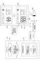
- the imaging device 10 is a digital camera and includes a lens unit 12 and an imaging device main body 14 .
- the imaging device 10 is an example of an “information processing device” and an “imaging device” according to the technology of the present disclosure.
- the imaging device 10 has a pitch axis, a yaw axis, and a roll axis.
- the axis P indicates the pitch axis of the imaging device 10
- the axis Y indicates the yaw axis of the imaging device 10
- the axis R indicates the roll axis of the imaging device 10 .
- the lens unit 12 is attached to the imaging device body 14 .
- a touch panel display 34 and instruction keys 36 are provided on the rear surface of the imaging device body 14 .
- the touch panel display 34 is formed by a touch panel 34A and a display 34B. For example, the touch panel 34A is superimposed on the display 34B.
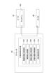
- An electronic viewfinder 28 is provided on the top of the imaging device body 14 .
- the electronic viewfinder 28 has a display 72 .
- a finder opening 16 is provided in the upper portion of the imaging device main body 14 , and the display 72 is provided inside the finder opening 16 .
- the display 72 is positioned so that the user can see the display 72 with his/her eyes 302 when looking through the viewfinder opening 16 .
- the display 72 is an example of a "display" according to the technology of the present disclosure.
- a light source 82 for line-of-sight detection and a line-of-sight sensor 86 are provided inside the viewfinder opening 16 .
- a user's eye 302 looking into the viewfinder opening 16 is a line-of-sight detection target.
- Light source 82 has a plurality of light emitters 82A. The plurality of light emitters 82A are arranged side by side in the pitch axis direction of the imaging device 10, for example.
- the light source 82 is arranged at a position where the user's eyes 302 can be illuminated with light when the user looks into the viewfinder opening 16 .
- the light source 82 emits near-infrared light, for example.
- the line-of-sight sensor 86 is arranged at a position where the user's eyes 302 can be imaged when the user looks into the viewfinder opening 16 .
- a half mirror (not shown) may be arranged inside the viewfinder opening 16 .
- the display 72 may be arranged on the passing optical axis of the half mirror, and the line-of-sight sensor 86 may be arranged on the reflecting optical axis of the half mirror.
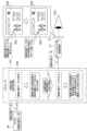
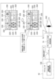
- the imaging device body 14 includes a computer 20, an image sensor 24, an image sensor control circuit 26, an electronic viewfinder 28, a line-of-sight detection unit 30, an image memory 32, a UI device 92, and an input device.
- An output I/F 38 is provided.
- the image sensor 24 , the image sensor control circuit 26 , the image memory 32 and the UI device 92 are connected to the input/output I/F 38 .
- the computer 20 comprises a processor 42, NVM 44, and RAM 46.
- the processor 42 controls the imaging device 10 as a whole.
- the processor 42 is, for example, a processing device that includes a CPU and a GPU.
- the GPU operates under the control of the CPU and is responsible for executing image processing.
- a processing device including a CPU and a GPU is mentioned here as an example of the processor 42, this is only an example, and the processor 42 may be one or more CPUs with integrated GPU functions, It may be one or more CPUs that do not integrate GPU functionality.
- Processor 42 , NVM 44 , and RAM 46 are connected via bus 48 , and bus 48 is connected to input/output I/F 38 .
- the computer 20 is an example of a "computer” according to the technology of the present disclosure.
- the processor 42 is an example of a "processor” according to the technology of the present disclosure.
- the NVM 44 is a non-temporary storage medium and stores various parameters and various programs.
- NVM 44 is flash memory (eg, EEPROM).
- flash memory eg, EEPROM
- HDD high-density diode
- the RAM 46 temporarily stores various information and is used as a work memory.
- the processor 42 reads necessary programs from the NVM 44 and executes the read programs in the RAM 46 .
- the processor 42 controls the image sensor 24 , the image sensor control circuit 26 , the electronic viewfinder 28 , the line-of-sight detection unit 30 , the image memory 32 , and the UI device 92 according to programs executed in the RAM 46 .
- the image sensor 24 is, for example, a CMOS image sensor.
- a CMOS image sensor is exemplified as the image sensor 24, but the technology of the present disclosure is not limited to this.
- the image sensor 24 may be another type of image sensor such as a CCD image sensor. technology is established.
- An image sensor control circuit 26 is connected to the image sensor 24 .
- the image sensor control circuit 26 controls the image sensor 24 according to the imaging control signal from the processor 42 .
- Subject light enters the imaging lens 52 of the lens unit 12, which will be described later.
- Subject light is imaged on the light receiving surface of the image sensor 24 by the imaging lens 52 .
- a photoelectric conversion element (not shown) is provided on the light receiving surface of the image sensor 24 .
- the photoelectric conversion element photoelectrically converts subject light received by the light-receiving surface, and outputs an electrical signal corresponding to the amount of subject light as analog image data representing the subject light. do.
- the image sensor 24 has a signal processing circuit (not shown).
- the signal processing circuit digitizes analog image data to generate digital captured image data and outputs the captured image data.
- the captured image data generated by the image sensor 24 is temporarily stored in the image memory 32 .
- the processor 42 acquires captured image data from the image memory 32 and executes various processes using the acquired captured image data.
- the lens unit 12 has an imaging lens 52 .
- the imaging lens 52 has an objective lens 54, a focus lens 56, a zoom lens 58, and an aperture 60, for example.
- the lens unit 12 also includes a lens control circuit 62 , a first actuator 64 , a second actuator 66 and a third actuator 68 .
- a lens control circuit 62 is connected to the first actuator 64 , the second actuator 66 , and the third actuator 68 , and the lens control circuit 62 is connected to the input/output I/F 38 .
- the lens control circuit 62 controls the first actuator 64 , the second actuator 66 and the third actuator 68 according to the lens control signal from the processor 42 .
- the first actuator 64 moves the focus lens 56 along the optical axis OA.
- the focus position is adjusted by changing the position of the focus lens 56 .
- a second actuator 66 moves the zoom lens 58 along the optical axis OA.
- the focal length is adjusted by changing the position of the zoom lens 58 .
- a third actuator 68 changes the size of the aperture of the diaphragm 60 . By changing the size of the aperture of the diaphragm 60, the aperture amount of the diaphragm 60 is changed, thereby adjusting the exposure.
- the first actuator 64, the second actuator 66, and the third actuator 68 are, for example, piezoelectric elements or voice coil motors.
- the electronic viewfinder 28 has a display 72 , a display control circuit 74 and an eyepiece 76 .
- the display 72 is, for example, a liquid crystal display or an EL display.
- the display control circuit 74 is connected to the input/output I/F 38 .
- the processor 42 selectively outputs captured image data, line-of-sight position data, gaze position data, and target area data to the display control circuit 74, as will be described later.
- the display control circuit 74 displays an image on the display 72 according to the imaged image data, line-of-sight position data, gaze position data, and target area data.
- the eyepiece lens 76 is arranged to face the screen of the display 72 .
- the line-of-sight detection unit 30 has a light source 82 , a light source control circuit 84 , a line-of-sight sensor 86 , and a line-of-sight sensor control circuit 88 .
- the light source 82 is, for example, an LED that outputs near-infrared light.
- the light source control circuit 84 is connected to the input/output I/F 38 .
- the light source control circuit 84 controls the light source 82 according to the light source control signal from the processor 42 .
- the line-of-sight sensor 86 is, for example, a CMOS image sensor sensitive to near-infrared light.
- a CMOS image sensor is exemplified as the line-of-sight sensor 86, but the technology of the present disclosure is not limited to this. technology is established.
- a line-of-sight sensor control circuit 88 is connected to the line-of-sight sensor 86 .
- the line-of-sight sensor control circuit 88 controls the line-of-sight sensor 86 according to the imaging control signal from the processor 42 .
- the line-of-sight sensor 86 captures an image of a subject (eg, the user's eye 302) and outputs line-of-sight data obtained by capturing the image.
- the UI device 92 has a display 34B.
- the processor 42 outputs display image data to the display 34B, and causes the display 34B to display an image and various information based on the display image data.
- the UI-based device 92 also includes a reception device 94 that receives instructions from the user.
- the reception device 94 has a touch panel 34A and a hard key section 96 .
- the hard key portion 96 is a plurality of hard keys including the instruction key 36 (see FIG. 1).
- the reception device 94 outputs reception data corresponding to various instructions received by the touch panel 34A and/or the hard key portion 96 .
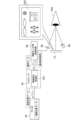
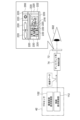
- FIG. 3 shows an example of a method for detecting the line-of-sight position based on the line-of-sight data.
- near-infrared light is emitted from a plurality of light emitters 82A to the eyeball 306, and the near-infrared light is reflected on the surface of the cornea 308, thereby forming a dotted pattern 234 on the surface of the cornea 308.
- a distance L1 between the patterns 234 is obtained from an image 238 obtained by capturing an image of the eyeball 306 with the line-of-sight sensor 86 .
- the distance between the line-of-sight sensor 86 and the eyeball 306 is calculated. is obtained.
- the positions of the center 310A of the pupil 310 and the outer shape 310B of the pupil 310 with respect to the center 238A of the image 238 are obtained from the image 238 obtained by capturing the image of the eyeball 306 with the line-of-sight sensor 86 .
- the eyeball Based on the positions of the center 310A of the pupil 310 and the outline 310B of the pupil 310 relative to the center 238A of the image 238, the distance L3 between the line-of-sight sensor 86 and the eyeball 306, and the preset radius of curvature for the eyeball 306, the eyeball
- the coordinates of the center 306A of the pupil 306 and the coordinates of the center 310A of the pupil 310 are determined. For example, a statistically determined numerical value is applied to the radius of curvature of the eyeball 306 .
- the direction in which the line 312 connecting the coordinates of the center 306A of the eyeball 306 and the coordinates of the center 310A of the pupil 310 extends corresponds to the direction of the line of sight of the eye 302.
- An extension line 314 obtained by extending the line 312 connecting the coordinates of the center 306A of the eyeball 306 and the coordinates of the center 310A of the pupil 310 indicates the line of sight of the eye 302, and the line of sight of the eye 302 and the screen of the display 72 intersect.
- a point P corresponding to the position of the line of sight of the eye 302 .
- the line-of-sight position of the eye 302 is detected based on the line-of-sight data obtained by imaging the eyeball 306 with the line-of-sight sensor 86 .
- the “line-of-sight position of the eye 302” is also referred to as the “line-of-sight position” or the “line-of-sight position with respect to the display 72”.
- the line-of-sight position is an example of the "line-of-sight position" according to the technology of the present disclosure.
- the method of detecting the line-of-sight position described above is merely an example, and the technology of the present disclosure is not limited to this.
- the line-of-sight to the display 72 can be detected based on the line-of-sight data obtained by imaging the eyeball 306 with the line-of-sight sensor 86 while the pattern 234 is formed on the surface of the cornea 308 .
- Various methods of position detection are applicable to the technology of the present disclosure.
- the line-of-sight position is detected based on the reflected light reflected by the surface of the cornea 308. , the line-of-sight position may be detected.
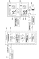
- the NVM 44 of the imaging device 10 stores a program 100 .
- the program 100 is an example of a "program" according to the technology of the present disclosure.
- Processor 42 reads program 100 from NVM 44 and executes read program 100 in RAM 46 .
- the processor 42 performs target area setting processing according to the program 100 executed by the RAM 46 .
- the processor 42 operates according to the program 100 as the captured image display control unit 102, the line-of-sight detection processing unit 104, the line-of-sight position display control unit 106, the gaze position display control unit 108, and the target region setting unit 110. is executed in
- the imaging device 10 has a plurality of operation modes and operates under designated operation modes.
- the target area setting process is executed, for example, when the target area setting mode is set as the operation mode of the imaging device 10 .
- the target area setting mode is set for the imaging device 10, for example, when an instruction to set the target area setting mode is received by the receiving device 94 (see FIG. 2).
- the target area setting mode setting instruction refers to, for example, an instruction to shift from an operation mode other than the target area setting mode to the target area setting mode.
- the captured image display control unit 102 causes the display 72 to display the captured image 200 .
- the captured image display control unit 102 performs the following processing. That is, the captured image display control unit 102 outputs an image capturing control signal to the image sensor control circuit 26 to capture an object (not shown) to the image sensor 24 via the image sensor control circuit 26 .
- the captured image display control unit 102 acquires captured image data obtained by capturing an image of the subject by the image sensor 24 and outputs the acquired captured image data to the display 72 .
- the display 72 displays the captured image 200 indicated by the captured image data. As a result, the captured image 200 including the subject as an image is displayed on the display 72 .
- Captured image data is an example of "first image data" according to the technology of the present disclosure.
- the captured image 200 is an example of a “first image” according to the technology of the present disclosure.
- the line-of-sight detection processing unit 104 detects the line-of-sight position of the user viewing the display 72 on which the captured image 200 is displayed. Specifically, the line-of-sight detection processing unit 104 performs the following processing. That is, the line-of-sight detection processing unit 104 outputs an imaging control signal to the line-of-sight sensor control circuit 88, thereby causing the line-of-sight sensor 86 to detect the subject (eg, the user's eyes) via the line-of-sight sensor control circuit 88. 302) is imaged.
- the line-of-sight detection processing unit 104 outputs an imaging control signal to the line-of-sight sensor control circuit 88, thereby causing the line-of-sight sensor 86 to detect the subject (eg, the user's eyes) via the line-of-sight sensor control circuit 88. 302) is imaged.
- the line-of-sight detection processing unit 104 acquires line-of-sight data obtained by imaging by the line-of-sight sensor 86, and detects the line-of-sight position with respect to the display 72 based on the acquired line-of-sight data.
- the method for detecting the line-of-sight position is as described with reference to FIG. Thereby, the line-of-sight position of the user viewing the display 72 on which the captured image 200 is displayed is detected.
- Line-of-sight data is an example of "line-of-sight data" according to the technology of the present disclosure.
- the line-of-sight detection processing unit 104 When the line-of-sight position is detected, the line-of-sight detection processing unit 104 generates line-of-sight position data indicating the line-of-sight position, and stores the line-of-sight position data in the RAM 46 .
- the light source 82 may continue to emit near-infrared light when the imaging device 10 is powered on. Further, the light source 82 emits near-infrared light when the line-of-sight position is detected by the line-of-sight detection processing unit 104, and emits near-infrared light when the line-of-sight position is not detected by the line-of-sight detection processing unit 104. may be stopped.
- the line-of-sight position display control unit 106 causes the display 72 to display a line-of-sight position mark 202 corresponding to the line-of-sight position. Specifically, the line-of-sight position display control unit 106 performs the following processing. That is, the line-of-sight position display control unit 106 acquires all the line-of-sight position data stored in the RAM 46 after the target area setting process was started. Based on the acquired line-of-sight position data, the line-of-sight position display control unit 106 then determines whether or not the change distance of the line-of-sight position is equal to or less than a predetermined distance.
- the change distance may be, for example, the total distance that the line-of-sight position has moved, but it is a distance that indicates the radius or diameter of the range in which the line-of-sight position has moved based on the first detected line-of-sight position.
- the change distance of the line-of-sight position is calculated by, for example, the average value or the maximum value of the change distance of the line-of-sight position indicated by all the line-of-sight position data stored in the RAM 46 .
- the default distance is set, for example, to a distance at which it is recognized that the line-of-sight position is being gazed at.
- the predetermined distance is an example of the "first distance" according to the technology of the present disclosure.
- the line-of-sight position display control unit 106 determines that the line-of-sight position variation distance is equal to or less than the predetermined distance, the line-of-sight position display control unit 106 outputs the line-of-sight position data including the line-of-sight position mark 202, which is a mark indicating the line-of-sight position, on the captured image 200 to the display 72. .
- the line-of-sight position indicated by the line-of-sight position mark 202 is set based on, for example, the average value of the line-of-sight positions indicated by all the line-of-sight position data stored in the RAM 46 .
- the display 72 superimposes and displays the line-of-sight position mark 202 indicated by the line-of-sight position data on the captured image 200 .
- the line-of-sight position mark 202 corresponding to the line-of-sight position is displayed on the display 72 .
- the line-of-sight position display control unit 106 determines whether or not the change distance of the line-of-sight position has continued for a predetermined time period or longer.
- the predetermined time is set, for example, to the time allowed for gazing at the line-of-sight position.
- the predetermined time is an example of the "first time” according to the technology of the present disclosure. If the line-of-sight position display control unit 106 determines that the line-of-sight position variation distance is equal to or less than the predetermined distance and has not continued for a predetermined period of time or longer, the process of acquiring the captured image data described above (see FIG. 5), the above-described line-of-sight The process of acquiring data (see FIG.
- line-of-sight position data is repeatedly output to the display 72 when the change distance of the line-of-sight position has not continued for a predetermined time or longer.
- line-of-sight position data indicating the line-of-sight position mark 202 specifying the line-of-sight position in the captured image 200 is output to the display 72 until the predetermined time is reached.
- the line-of-sight position data is an example of "data indicating a line-of-sight position mark" according to the technology of the present disclosure.
- the line-of-sight position mark 202 is an example of the “line-of-sight position mark” according to the technology of the present disclosure.
- the line-of-sight position display control unit 106 When repeatedly outputting the line-of-sight position data to the display 72, the line-of-sight position display control unit 106 changes the form of the line-of-sight position mark 202 over time. For example, the line-of-sight position display control unit 106 performs a process of darkening the color of the line-of-sight position mark 202 over time. Note that the line-of-sight position display control unit 106 may, for example, perform a process of darkening aspects other than color, such as the shape of the line-of-sight position mark 202, over time.
- gaze position display control unit 106 determines that the change distance of the gaze position has continued for a predetermined time or longer, the captured image 200 is displayed.
- the gaze position is detected as the gaze position when the change distance of the gaze position with respect to the object continues for a predetermined time or longer.
- gaze position display control section 108 outputs gaze position data including gaze position mark 204 , which is a mark indicating the gaze position, on captured image 200 to display 72 .
- gaze position data indicating the gaze position mark 204 specifying the gaze position in the captured image 200 is output to the display 72 .
- the display 72 superimposes the gaze position mark 204 indicated by the gaze position data on the captured image 200 instead of the gaze position mark 202 and displays it.
- the gaze position mark 204 is preferably different from the gaze position mark 202 in order to indicate that the gaze position has been detected from the gaze position.
- the gaze position mark 204 is displayed in a darker color than the line-of-sight position mark 202 .
- the gaze position is an example of the "gazing position" according to the technology of the present disclosure.
- the gaze position data is an example of "data indicating a gaze position mark” according to the technology of the present disclosure.
- the gaze position mark 204 is an example of the "gaze position mark” according to the technology of the present disclosure.
- the gaze position display control unit 108 After outputting the gaze position data to the display 72, the gaze position display control unit 108 deletes the gaze position data stored in the RAM 46. Further, when the gaze position is detected, the gaze position display control unit 108 generates gaze position data indicating the gaze position, and stores the gaze position data in the RAM 46 . A plurality of pieces of gaze position data are stored in the RAM by repeatedly executing the processing from acquiring the above-described captured image data to storing the gaze position data in the RAM 46 .
- the target region setting unit 110 sets a target region 206 for the captured image 200 based on a plurality of gaze positions. Specifically, the target area setting unit 110 performs the following processing. That is, the target area setting unit 110 acquires all gaze position data stored in the RAM 46 after the start of the target area setting process. Subsequently, the target region setting unit 110 determines whether or not the number of detected gaze positions has reached a predetermined number based on the acquired gaze position data. The number of gaze positions detected corresponds to the number of gaze position data stored in the RAM 46 . The predetermined number is set to a number that allows the target region 206 to be set for the captured image 200 based on the gaze position. In the first embodiment, the default number is set to 2 as an example.
- the target area setting unit 110 determines that the number of detected gaze positions has not reached the predetermined number
- the above-described processing from acquiring the captured image data to outputting the gaze position data is executed again.
- two gaze positions are detected by repeatedly executing the process from acquiring the above-described captured image data to outputting gaze position data, and two gaze position marks 204 are displayed on the display 72. Displayed states are shown.
- the target region setting unit 110 determines that the number of detected gaze positions has reached the predetermined number, the target region setting unit 110 sets the target region 206 in the captured image 200 based on the detected gaze positions.
- the target area setting unit 110 sets, for example, a rectangular area diagonal to the gaze positions indicated by the two gaze position marks 204 as the target area 206 for the captured image 200 . In this manner, the target area 206 is set for the captured image 200 based on a plurality of gaze positions.
- the target area setting unit 110 outputs target area data including the target area frame 208 indicating the target area 206 in the captured image 200 to the display 72 .
- the display 72 displays a target area frame 208 indicated by the target area data so as to be superimposed on the captured image 200 and the gaze position mark 204 .
- the target area 206 is an example of a "first area" according to the technology of the present disclosure.
- the target area 206 set in the manner described above is used, for example, for adjustment of exposure by automatic exposure and/or adjustment of image quality by automatic white balance.
- the target area setting process may be executed from the beginning when, for example, an instruction to erase the gaze position is received by the receiving device 94 (see FIG. 2) in the process of setting the above-described area. This makes it possible to redo the setting of the gaze position when the gaze position is set at an undesired position by the user.
- the default number is set to 2 as an example, but the default number may be set to 3 or more. That is, the number of gaze positions detected may be three or more.
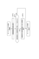
- FIG. 10 shows an example of the flow of target area setting processing according to the first embodiment.
- step ST10 the captured image display control section 102 causes the image sensor 24 to capture an image of the subject. Then, the captured image display control unit 102 acquires captured image data obtained by capturing an image of the subject by the image sensor 24 . After the process of step ST10 is executed, the target area setting process proceeds to step ST11.
- step ST11 the captured image display control unit 102 outputs the captured image data acquired at step ST10 to the display 72. Thereby, the captured image 200 is displayed on the display 72 .
- step ST12 the target area setting process proceeds to step ST12.
- step ST12 the line-of-sight detection processing unit 104 acquires line-of-sight data captured by the line-of-sight sensor 86. After the process of step ST12 is executed, the target area setting process proceeds to step ST13.
- step ST13 the line-of-sight detection processing unit 104 detects the line-of-sight position with respect to the display 72 based on the line-of-sight data acquired at step ST12. After the process of step ST13 is executed, the target area setting process proceeds to step ST14.
- step ST14 the line-of-sight detection processing unit 104 generates line-of-sight position data indicating the line-of-sight position detected in step ST13, and stores the line-of-sight position data in the RAM46.
- step ST14 the target area setting process proceeds to step ST15.
- step ST15 the line-of-sight position display control unit 106 acquires all the line-of-sight position data stored in the RAM 46 after the target area setting process is started, and based on the acquired line-of-sight position data, the change distance of the line-of-sight position is calculated. Determine whether or not the distance is less than or equal to the predetermined distance. In step ST15, if the change distance of the line-of-sight position is not equal to or less than the predetermined distance, the determination is negative, and the target area setting process proceeds to step ST10. In step ST15, when the change distance of the line-of-sight position is equal to or less than the predetermined distance, the determination is affirmative, and the target area setting process proceeds to step ST16.
- step ST16 the line-of-sight position display control unit 106 outputs line-of-sight position data including the line-of-sight position mark 202 indicating the line-of-sight position to the display 72.
- the line-of-sight position mark 202 indicated by the line-of-sight position data is superimposed on the captured image 200 and displayed on the display 72 .
- step ST17 the line-of-sight position display control unit 106 determines whether or not the change distance of the line-of-sight position has continued for a predetermined time period or longer. In step ST17, if the line-of-sight position variation distance has not continued for a predetermined time or longer, the determination is negative, and the target area setting process proceeds to step ST10. In step ST17, if the change distance of the line-of-sight position has continued for a predetermined time or longer, the determination is affirmative, and the target area setting process proceeds to step ST18.
- step ST18 the gaze position display control unit 108 detects the gaze position as the gaze position, and outputs gaze position data including the gaze position mark 204 indicating the detected gaze position to the display 72.
- the gaze position mark 204 indicated by the gaze position data is superimposed on the captured image 200 and displayed on the display 72 .
- step ST19 the gaze position display control unit 108 erases the line-of-sight position data stored in the RAM46. After the process of step ST19 is executed, the target area setting process proceeds to step ST20.
- step ST20 the gaze position display control unit 108 generates gaze position data indicating the gaze position detected in step ST18, and stores the gaze position data in the RAM46. After the process of step ST20 is executed, the target area setting process proceeds to step ST21.
- step ST21 the target area setting unit 110 acquires all gaze position data stored in the RAM 46 after the target area setting process was started, and based on the acquired gaze position data, the number of detected gaze positions determines whether or not has reached a predetermined number. In step ST21, if the number of detected gaze positions has not reached the predetermined number, the determination is negative, and the target area setting process proceeds to step ST10. In step ST21, when the number of detected gaze positions reaches the predetermined number, the determination is affirmative, and the target area setting process proceeds to step ST22.
- step ST22 the target area setting unit 110 sets the target area 206 for the captured image 200 based on the multiple gaze positions indicated by the multiple gaze position data stored in the RAM in step ST20. After the process of step ST22 is executed, the target area setting process proceeds to step ST23.
- the target area setting section 110 outputs to the display 72 target area data including the target area frame 208 indicating the target area 206 set at step ST22.
- the target area frame 208 indicated by the target area data is displayed on the display 72 while being superimposed on the captured image 200 and the gaze position mark 204 .
- the target area setting process ends.
- the information processing method described as the action of the imaging device described above is an example of the “information processing method” according to the technology of the present disclosure.
- the processor 42 acquires captured image data and outputs the captured image data to the display 72 .
- the processor 42 acquires the line-of-sight data, and based on the line-of-sight data, gazes at the line-of-sight position when the change distance of the line-of-sight position with respect to the captured image 200 indicated by the captured image data is equal to or less than a predetermined distance for a predetermined time or longer. Detect as a position.
- Processor 42 then establishes region of interest 206 based on the two or more gaze positions. Therefore, the target area 206 can be set for the captured image 200 based on the line-of-sight position.
- the processor 42 sets a rectangular area having two gazing positions as diagonals as the target area 206 . Therefore, the target area 206, which is a rectangular area, can be set for the captured image 200 based on the two line-of-sight positions.
- the processor 42 outputs line-of-sight position data indicating the line-of-sight position mark 202 for specifying the line-of-sight position within the captured image 200 until the predetermined time is reached, and when the predetermined time is reached, the line-of-sight position within the captured image 200 is output. Gaze position data indicating the specified gaze position mark 204 is output. Therefore, by gazing at the captured image 200 until the predetermined time is reached, the gaze position mark 204 can be displayed at the gazed position.
- the line-of-sight position mark 202 changes in appearance over time. Therefore, for example, it is possible to make the user recognize that the captured image 200 is being watched, as compared with the case where the line-of-sight position mark 202 has a constant aspect.
- the target region setting unit 110 when setting a target region 206 based on a gaze position, sets a circular region whose diameter is a line connecting two gaze positions in the captured image 200. may be set as the region of interest 206 for
- the area set based on two or more gaze positions may have any shape.
- FIG. 12 shows the second embodiment.
- the following changes are made with respect to the first embodiment.
- the second embodiment will be described below based on an example in which four gaze positions are detected.
- the plurality of gaze position marks 204 are designated as gaze position mark 204A, gaze position mark 204B, and gaze position mark 204C. , and gaze position mark 204D.
- the gaze position corresponding to each gaze position mark 204 is detected in order of gaze position mark 204A, gaze position mark 204B, gaze position mark 204C, and gaze position mark 204D.
- the default number for setting target regions 206 based on gaze positions is set to four.
- the target region setting unit 110 acquires all gaze position data stored in the RAM 46 after the target region setting process is started, and based on the acquired gaze position data, sets the number of detected gaze positions to a predetermined number. Determine whether or not it has been reached.
- the target region setting unit 110 determines that the number of detected gaze positions has reached the predetermined number
- the target region setting unit 110 sets the target region 206 for the captured image 200 .
- the target region setting unit 110 sets, for example, a closed region determined by connecting the four gaze positions indicated by the four gaze position marks 204 in the detected order as the target region 206 for the captured image 200 .
- the target area setting unit 110 outputs target area data including the target area frame 208 , which is a mark indicating the target area 206 in the captured image 200 , to the display 72 .
- the display 72 displays a target area frame 208 indicated by the target area data so as to be superimposed on the captured image 200 and the gaze position mark 204 .
- the processor 42 sets, as the target area 206 for the captured image 200, a closed area determined by connecting the four gaze positions in the order in which they are detected. Therefore, the target area 206, which is a closed area, can be set for the captured image 200 based on the four line-of-sight positions.
- the target region 206 may be set based on three gaze positions, or may be set based on five or more gaze positions.
- FIG. 13 shows the third embodiment.
- the gaze position is called gaze position 210 .
- the third embodiment will be described below based on an example in which five gaze positions 210 are detected.
- the plurality of gaze positions 210 are referred to as gaze position 210A, gaze position 210B, gaze position 210C, gaze position 210D, and gaze position 210E.
- the gaze position 210 is detected in order of gaze position 210A, gaze position 210B, gaze position 210C, gaze position 210D, and gaze position 210E.
- the target region setting unit 110 acquires all the gaze position data stored in the RAM 46 after the target region setting process is started, and sets the target region 206 (Fig. 14) can be set. For example, when the target region setting unit 110 detects three or more gaze positions 210 as in the example shown in FIG. If the intersection position 214 is set at the position where the line 212B connecting 210E intersects, the target area 206 can be set based on the gaze position 210B, the gaze position 210C, the gaze position 210D, and the intersection position 214. It is determined that the target area 206 can be set based on the plurality of gaze positions 210 . Then, when the target region setting unit 110 determines that the target region 206 can be set based on the plurality of gaze positions 210, the position where the lines 212A and 212B connecting the two gaze positions 210 intersect is set as the intersection position. 214.
- the target region setting unit 110 sets the target region 206 based on the gaze position 210B, the gaze position 210C, the gaze position 210D, and the intersection position 214 that exist at positions where the target region 206 can be defined.
- a region 206 is set. That is, a closed area determined by connecting the gaze position 210B, the gaze position 210C, the gaze position 210D, and the intersection position 214 is set as the target area 206 for the captured image 200.
- FIG. thus, at least 4+1 fixation positions 210 are used when setting a region of interest 206 having four vertices.
- the target area setting unit 110 outputs target area data including the target area frame 208 which is a mark indicating the target area 206 in the captured image 200 to the display 72 .
- the target region setting unit 110 also provides gaze position data including a gaze position mark 204, which is a mark indicating a gaze position 210 defining a target region 206 in the captured image 200, and a mark indicating an intersecting position 214 in the captured image 200.
- Intersection data including intersection mark 216 is output to display 72 .
- the display 72 superimposes and displays a gaze position mark 204, an intersection position mark 216, and a target area frame 208 on the captured image 200 based on the gaze position data, the intersection position data, and the area data.
- the gaze position marks 204 displayed on the display 72 corresponding to the five gaze positions 210 instead of the plurality of gaze position marks 204 displayed on the display 72 corresponding to the five gaze positions 210, the gaze position marks 204 defining the target area 206, the intersection position mark 216, and the target area frame 208 are displayed. is displayed.
- the processor 42 sets the position where the lines 212A and 21B connecting the two gaze positions 210 intersect as the intersection position 214, and the target region 206 A target region 206 is set based on a gaze position 210 and an intersection position 214 that exist at positions that can define . Therefore, even if lines 212A and 212B connecting two gaze positions 210 are generated in the process of setting the target region 206, the target region 206, which is a closed region, can be set.
- the target area 206 is set based on the five gaze positions 210, but may be set based on the four gaze positions 210.
- FIG. In this case, a triangular region of interest 206 is set.
- at least 3+1 fixation positions 210 are used when setting a region of interest 206 having three vertices.
- the region of interest 206 may have a shape with n vertices. n is a natural number. At least 4+1 fixation positions 210 are used when setting a region of interest 206 having n vertices.
- the CPU operates as the trajectory display control section 112 .
- the trajectory display control unit 112 causes the display 72 to display a trajectory line 218 corresponding to the line-of-sight position.
- the trajectory display control unit 112 performs the following processing. That is, the trajectory display control unit 112 acquires all line-of-sight position data stored in the RAM 46 after the target area setting process was started. Subsequently, the line-of-sight position display control unit 106 detects a trajectory determined by connecting the plurality of line-of-sight positions in the order in which the line-of-sight positions are detected, based on the plurality of acquired line-of-sight position data.
- the line-of-sight position display control unit 106 outputs the trajectory data including the trajectory line 218 indicating the trajectory to the display 72 .
- the display 72 superimposes the trajectory line 218 indicated by the trajectory data on the captured image 200 and displays it.
- the trace line 218 corresponding to the line-of-sight position is displayed on the display 72 .
- a trajectory is an example of a 'trajectory' according to the technology of the present disclosure.
- the trajectory display control unit 112 determines whether or not the state in which the trajectory has been detected has continued for a predetermined time or longer.
- the predetermined time may be, for example, the time from when the receiving device 94 (see FIG. 2) starts receiving an instruction from the user until it ends. Further, the predetermined time may be the time from when the acceptance of the instruction from the user is started until the predetermined time (for example, the time when the trajectory for setting the area can be secured) elapses. It may be the time from when the user starts to look at 72 until when the user looks away from the display 72 .
- the predetermined time is an example of the "second time" according to the technology of the present disclosure.
- the trajectory display control unit 112 determines that the state in which the trajectory has been detected has not continued for a predetermined time or longer, the trajectory display control unit 112 performs the process of acquiring the captured image data (see FIG. 5) and the process of acquiring the line-of-sight data (see FIG. 5). 6), and the process of outputting the locus data described above are executed again.
- the locus data is repeatedly output to the display 72 when the state in which the locus has been detected does not continue for a predetermined time or longer.
- the trajectory along which the line-of-sight position has changed is detected until the predetermined time is reached, and trajectory data including a trajectory line 218 that is a line indicating the detected trajectory is output to the display 72 .
- captured image data is an example of "second image data" according to the technology of the present disclosure.
- a captured image 200 indicated by captured image data is an example of a “second image” according to the technology of the present disclosure.
- the target region setting unit 110 sets a target region 206 for the captured image 200 based on the detected trajectory. Specifically, the target area setting unit 110 performs the following processing. That is, when the trajectory display control unit 112 determines that the state in which the trajectory has been detected has continued for a predetermined time or longer, the target region setting unit 110 sets the closed region surrounding the trajectory indicated by the trajectory line 218 to the target region 206 of the captured image 200 . set as In this case, the target region setting unit 110 may set a closed region circumscribing the trajectory as the target region 206 for the captured image 200, or set a closed region away from the trajectory and surrounding the trajectory as the target region 206 for the captured image 200. May be set. In this manner, the target area 206 is set for the captured image 200 based on the trajectory.
- the target area 206 is an example of a "second area" according to the technology of the present disclosure.
- the target area setting unit 110 outputs target area data including the target area frame 208 which is a mark indicating the target area 206 in the captured image 200 to the display 72 .
- the display 72 displays the target area frame 208 indicated by the target area data so as to be superimposed on the captured image 200 and the trajectory line 218 .
- FIG. 17 shows an example of the flow of target area setting processing according to the fourth embodiment.
- step ST30 to step ST34 is the same as the process from step ST10 to step ST14 (see FIG. 10) in the target area setting process according to the first embodiment.
- the target area setting process shown in FIG. 17 proceeds to step ST35 after the process of step ST34 is executed.
- step ST35 the trajectory display control unit 112 acquires all the line-of-sight position data stored in the RAM 46 after the target area setting process is started, and calculates a plurality of line-of-sight positions based on the plurality of acquired line-of-sight position data. A trajectory determined by connecting multiple line-of-sight positions in the order of detection is detected. Then, the line-of-sight position display control unit 106 outputs to the display 72 trajectory data including a trajectory line 218 that is a mark indicating the trajectory. Thereby, the trajectory line 218 indicated by the trajectory data is superimposed on the captured image 200 and displayed on the display 72 .
- step ST36 the trajectory display control unit 112 determines whether or not the state in which the trajectory has been detected has continued for a predetermined time or longer. In step ST36, if the state in which the trajectory has been detected has not continued for the predetermined time or longer, the determination is negative, and the target area setting process proceeds to step ST30. In step ST36, if the state in which the trajectory has been detected continues for the predetermined time or longer, the determination is affirmative, and the target area setting process proceeds to step ST37.
- step ST37 the target area setting unit 110 sets a closed area surrounding the trajectory detected at step ST35 as the target area 206 for the captured image 200. After the process of step ST37 is executed, the target area setting process proceeds to step ST38.
- the target area setting section 110 outputs to the display 72 target area data including the target area frame 208 indicating the target area 206 set at step ST37.
- the target area frame 208 indicated by the target area data is superimposed on the captured image 200 and displayed on the display 72 .
- the target area setting process ends.
- the information processing method described as the action of the imaging device described above is an example of the “information processing method” according to the technology of the present disclosure.
- the processor 42 acquires captured image data and outputs the captured image data to the display 72 .
- the processor 42 acquires line-of-sight data, and based on the line-of-sight data, detects a trajectory along which the line-of-sight position has changed within a predetermined time with respect to the captured image 200 indicated by the captured image data.
- Processor 42 sets target region 206 based on the trajectory. Therefore, the target area 206 can be set for the captured image 200 based on the trajectory of the line-of-sight position change.
- the processor 42 sets a closed area surrounding the trajectory as the target area 206 for the captured image 200 . Therefore, it is possible to set the target area 206, which is a closed area surrounding the trajectory, based on the trajectory in which the line-of-sight position has changed.
- the target region setting unit 110 may set a closed region (for example, a rectangular region) inscribed in the trajectory indicated by the trajectory line 218 as the target region 206 for the captured image 200. .
- the target region setting unit 110 sets the closed region formed by the trajectory as the target region 206 for the captured image 200. May be set. That is, the area surrounded by the trajectory may be set as the target area 206 for the captured image 200 .
- FIG. 20 shows a fifth embodiment.
- the following changes are made with respect to the fourth embodiment.
- the trajectory display control unit 112 determines whether or not blinking has occurred, and outputs trajectory data generated based on the determination result to the display 72 . Specifically, the trajectory display control unit 112 performs the following processing. That is, the trajectory display control unit 112 determines whether or not blinking occurs during the time period during which the trajectory is being detected, based on the line-of-sight position data stored in the RAM 46 .
- the line-of-sight position data stored in the RAM 46 includes, in addition to the line-of-sight position data obtained when the eye is not blinking (that is, when the eye 302 is open), 302 is closed) is also included.
- the trajectory display control unit 112 detects eye gaze position data acquired while blinking (that is, when the eyes 302 are closed), it determines that a blink has occurred.
- the line-of-sight position data acquired when the user is blinking may include error information indicating that the line-of-sight position was not detected. If the line-of-sight position data obtained from the RAM includes line-of-sight position data including error information, the trajectory display control unit 112 determines that blinking has occurred.
- the trajectory display control unit 112 calculates the first line-of-sight position before the blink and the blink based on the line-of-sight position data acquired before and after the line-of-sight position data in the case of blinking.
- the trajectory is detected by performing linear interpolation connecting the second line-of-sight position after the occurrence of . That is, the trajectory display control unit 112 detects the trajectory based on the line connecting the first line-of-sight position before blinking and the second line-of-sight position after blinking. Then, the trajectory display control unit 112 outputs trajectory data indicating the trajectory to the display 72 .
- the locus data generated based on the result of determining whether or not blinking has occurred is output to the display 72 .
- the display 72 superimposes the trajectory line 218 indicated by the trajectory data on the captured image 200 and displays it.
- a first line-of-sight position mark 202A indicating the first line-of-sight position
- a second line-of-sight position mark 202B indicating the second line-of-sight position
- a line connecting the first line-of-sight position and the second line-of-sight position may be superimposed on the captured image 200 and displayed. If the first line-of-sight position and the second line-of-sight position are so far apart that linear interpolation cannot be performed, the trajectory display control unit 112 may cause the display 72 to display characters or the like indicating an error.
- FIG. 21 shows an example of the flow of target area setting processing according to the fifth embodiment.
- step ST40 to step ST41 is added to the target area setting process (see FIG. 17) according to the fourth embodiment.
- the processing from step ST30 to step ST34 is the same as the target area setting processing according to the fourth embodiment.
- the target area setting process shown in FIG. 17 proceeds to step ST40 after the process of step ST34 is executed.
- the trajectory display control unit 112 determines whether or not blinking occurs during the time period during which the trajectory is being detected, based on the line-of-sight position data acquired at step ST34. In step ST40, if blinking has not occurred during the time period during which the trajectory is being detected, the determination is negative, and the target area setting process proceeds to step ST35. In step ST40, if blinking occurs during the time period during which the trajectory is being detected, the determination is affirmative, and the target area setting process proceeds to step ST41.
- step ST41 when determining that a blink has occurred, the trajectory display control unit 112, based on the line-of-sight position data acquired before and after the line-of-sight position data in the case of blinking, determines the first line of sight before the blink.
- the trajectory is detected by performing linear interpolation connecting the line-of-sight position and the second line-of-sight position after the occurrence of the blink.
- the processing from step ST35 to step ST38 is the same as the target area setting processing according to the fourth embodiment.
- the processor 42 determines whether or not blinking occurs during the time period during which the trajectory is being detected, based on the line-of-sight position data obtained from the line-of-sight data. Then, when the processor 42 determines that the blink has occurred, the processor 42 detects the trajectory based on the line connecting the first line-of-sight position before the blink and the second line-of-sight position after the blink. Therefore, even when blinking occurs, the target area 206 can be set based on the trajectory.
- the captured image display control unit 102 causes the display 72 to display a division grid 222 that divides the captured image 200 into a plurality of areas 220 .
- the captured image display control unit 102 performs the following processing. That is, the captured image display control unit 102 outputs an image capturing control signal to the image sensor control circuit 26 to capture an object (not shown) to the image sensor 24 via the image sensor control circuit 26 .
- the captured image display control unit 102 acquires captured image data obtained by capturing an image of a subject by the image sensor 24 .
- the captured image display control unit 102 divides the captured image 200 into a plurality of areas 220.
- the captured image display control unit 102 may divide the captured image 200 into a plurality of areas 220 in accordance with instructions from the user received by the receiving device 94 (see FIG. 2).
- the captured image 200 may be divided into a plurality of regions 220 based on the result of performing image processing on the .
- the captured image display control unit 102 may divide the captured image 200 into a plurality of regions 220 based on information regarding the depth of field and the like obtained from the captured image data.
- the plurality of regions 220 is an example of the “plurality of regions” according to the technology of the present disclosure.
- the captured image display control unit 102 generates region division data indicating division grids 222 that divide the captured image 200 into a plurality of regions 220 and outputs the captured image data and the region division data to the display 72 .
- the display 72 displays the captured image 200 indicated by the captured image data.
- the captured image 200 in which the subject appears as an image is displayed on the display 72 .
- the display 72 displays the division grid 222 indicated by the area division data by superimposing it on the captured image 200 . In this manner, a division grid 222 that divides the captured image 200 into a plurality of areas 220 is displayed on the display 72 .
- the line-of-sight position display control unit 106 outputs the line-of-sight position data to the display 72 in the same manner as in the first embodiment, thereby displaying the line-of-sight position mark 202 corresponding to the line-of-sight position on the display 72. display.
- the line-of-sight position display control unit 106 changes the form of the line-of-sight position mark 202 over time. For example, the line-of-sight position display control unit 106 darkens the color of the line-of-sight position mark 202 over time.
- the gaze position display control unit 108 detects the gaze position as the gaze position in the same manner as in the first embodiment. Then, the gaze position display control unit 108 superimposes the gaze position mark 204 on the captured image 200 by outputting to the display 72 gaze position data including the gaze position mark 204 that indicates the gaze position on the captured image 200 . to display on the display 72. Then, a plurality of gaze positions are detected by repeatedly executing the process from acquiring the above-described captured image data to detecting the gaze position.
- two gaze positions are detected by repeatedly executing the process from acquiring the above-described captured image data to detecting the gaze position, and two gaze position marks 204 are displayed on the display 72. is shown.
- the target region setting unit 110 sets the target region 206 from the plurality of regions 220 based on the plurality of gaze positions.
- the target region setting unit 110 extracts, from the plurality of regions 220, a region that fits in a rectangular region having two gaze positions indicated by the two gaze position marks 204 as diagonal corners, and converts the extracted region into a captured image. 200 as the region of interest 206 .
- target area setting section 110 outputs target area data including target area frame 208 , which is a frame indicating target area 206 in captured image 200 , to display 72 .
- the display 72 superimposes and displays the target area frame 208 indicated by the target area data on the captured image 200 .
- a region is set from a plurality of regions 220 included in the captured image 200 based on two gaze positions.
- a region may be set from a plurality of regions 220 .
- FIG. 26 shows an example of the flow of target area setting processing according to the sixth embodiment.
- step ST50 is added to the target area setting process according to the first embodiment (see FIG. 10).
- the target area setting process shown in FIG. 27 proceeds to step ST50 after the process of step ST10 is executed.
- step ST50 the captured image display control unit 102 generates area division data indicating division grids 222 that divide the captured image 200 into a plurality of areas 220 .
- step ST50 the target area setting process proceeds to step ST11.
- step ST11 the captured image display control unit 102 outputs the captured image data acquired in step ST10 and the segmented data generated in step ST50 to the display 72.
- the display 72 displays the captured image 200 indicated by the captured image data.
- the display 72 displays a division grid 222 indicated by the area division data, superimposed on the captured image 200 .
- step ST12 the target area setting process proceeds to step ST12.
- the processing from step ST12 to step ST21 is the same as the target area setting processing according to the first embodiment.
- the target area setting unit 110 sets the target area 206 from the plurality of areas 220 based on the plurality of gaze positions indicated by the plurality of gaze position data stored in the RAM at step ST20.
- the target area setting process proceeds to step ST23.
- the process of step ST23 is the same as the target area setting process according to the first embodiment.
- the processor 42 sets the target area 206 from the plurality of areas 220 included in the captured image 200 based on two or more gaze positions. Therefore, the target area 206 can be set for the captured image 200 based on the line-of-sight position.
- the target area setting unit 110 may extract from a plurality of areas 220 an area that fits within a circular area whose diameter is the line connecting the two gaze positions, and set the extracted area 220 as the target area 206.
- the target region setting unit 110 extracts from the plurality of regions 220 a region that fits within a closed region determined by connecting the plurality of gaze positions in the order in which the plurality of gaze positions are detected, and sets the extracted region 220 as the target region 206. You may
- FIGS. A seventh embodiment is shown in FIGS. In the seventh embodiment, the following changes are made to the fourth embodiment.
- the captured image display control unit 102 causes the display 72 to display a division grid 222 that divides the captured image 200 into a plurality of areas 220, as in the sixth embodiment.
- the trajectory display control unit 112 outputs the trajectory data including the trajectory line 218, which is the line indicating the trajectory, to the display 72, thereby superimposing the trajectory line 218 indicated by the trajectory data on the captured image 200. display.
- the target area setting unit 110 sets the target area 206 from the plurality of areas 220 based on the trajectory indicated by the trajectory line 218 .
- the target region setting unit 110 extracts, for example, a region 220 that overlaps the trajectory from the plurality of regions 220 and sets the extracted region 220 as the target region 206 for the captured image 200 .
- target area setting section 110 outputs target area data including target area frame 208 , which is a frame indicating target area 206 in captured image 200 , to display 72 .
- the display 72 superimposes and displays the target area frame 208 indicated by the target area data on the captured image 200 .
- FIG. 29 shows an example of the flow of target area setting processing according to the seventh embodiment.
- step ST60 is added to the target area setting process (see FIG. 17) according to the fourth embodiment.
- the target area setting process shown in FIG. 29 proceeds to step ST60 after the process of step ST30 is executed.
- step ST60 the captured image display control unit 102 generates area division data indicating division grids 222 that divide the captured image 200 into a plurality of areas 220 .
- the target area setting process proceeds to step ST31.
- step ST31 the captured image display control unit 102 outputs the captured image data acquired in step ST30 and the segmented data generated in step ST60 to the display 72.
- the display 72 displays the captured image 200 indicated by the captured image data.
- the display 72 displays a division grid 222 indicated by the area division data, superimposed on the captured image 200 .
- step ST32 the target area setting process proceeds to step ST32.
- the processing from step ST32 to step ST36 is the same as the target area setting processing according to the fourth embodiment.
- step ST37 the target area setting section 110 sets the target area 206 from the plurality of areas 220 based on the trajectory detected at step ST35.
- step ST38 the target area setting process proceeds to step ST38.
- the process of step ST38 is the same as the target area setting process according to the fourth embodiment.
- the processor 42 sets the target area 206 from the plurality of areas 220 included in the captured image 200 based on the trajectory. Therefore, the target area 206 can be set for the captured image 200 based on the trajectory detected along with the change in line-of-sight position.
- the target area setting unit 110 may extract the area surrounding the trajectory from a plurality of areas 220 and set the extracted area 220 as the target area 206 for the captured image 200 .
- the target region setting unit 110 may also extract a region surrounded by the trajectory from a plurality of regions 220 and set the extracted region 220 as the target region 206 for the captured image 200 .
- FIG. 30 shows an eighth embodiment.
- the eighth embodiment the following changes are made with respect to the first embodiment.
- the processor 42 operates as an autofocus processing unit 114.
- the autofocus processing unit 114 performs control to keep the target subject 224 within the depth of field.
- the autofocus processing unit 114 performs the following processing. That is, the autofocus processing unit 114 first executes target area setting processing. For the target area setting process, for example, the target area setting process in any one of the first to seventh embodiments described above is applied. Thereby, the target area 206 is set for the captured image 200 , and the captured image 200 and the target area frame 208 are displayed on the display 72 .
- target area setting process for example, the target area setting process in any one of the first to seventh embodiments described above is applied.
- the target area 206 is set for the captured image 200 , and the captured image 200 and the target area frame 208 are displayed on the display 72 .
- the autofocus processing unit 114 determines whether or not the target subject 224 is included as an image within the target region 206 in the captured image 200 .
- the autofocus processing unit 114 uses an image processing technique such as pattern matching to image the target subject 224 in the target region 206 based on the captured image data acquired in the target region setting process. Determine whether it is included as
- the target subject 224 refers to a subject to be included within the depth of field as described later.
- the target subject 224 is an example of a "target subject" according to the technology of the present disclosure.
- the target subject 224 is a person's face.
- the target subject 224 may be an animal face, or a subject other than a face, in addition to a person's face.
- the display 72 may display a detection frame 226 indicating a frame surrounding the target subject 224 so as to be superimposed on the captured image 200. .
- the autofocus processing unit 114 determines that the target subject 224 is included as an image within the target region 206, it performs control to keep the target subject 224 within the depth of field. That is, the autofocus processing unit 114 outputs a lens control signal to the lens control circuit 62 to control the first actuator 64 via the lens control circuit 62, thereby adjusting the position of the focus lens 56. The position is adjusted so that the target subject 224 is within the depth of field. In this way, control is performed to keep the target subject 224 within the depth of field.
- FIG. 31 shows an example of the flow of autofocus processing according to the eighth embodiment.
- step ST70 the autofocus processing section 114 executes target area setting processing. Thereby, the target area 206 is set for the captured image 200 , and the captured image 200 and the target area frame 208 are displayed on the display 72 . After the process of step ST70 is executed, the autofocus process proceeds to step ST71.
- step ST71 the autofocus processing unit 114 determines whether or not the target subject 224 is included as an image within the target region 206, based on the target region data acquired in the target region setting process executed in step ST70. do. In step ST71, if the target subject 224 is not included as an image within the target area 206, the determination is negative, and the autofocus processing ends. In step ST71, if the target subject 224 is included as an image within the target area 206, the determination is affirmative, and the autofocus process proceeds to step ST72.
- step ST72 the autofocus processing unit 114 performs control to keep the target subject 224 within the depth of field. This allows the target subject 224 to fit within the depth of field. After the process of step ST72 is executed, the autofocus process ends.
- the processor 42 when the target subject 224 is included as an image within the target region 206, the processor 42 performs control to keep the target subject 224 within the depth of field. Therefore, for example, in autofocus processing, the target subject 224 can be kept within the depth of field based on the line-of-sight position.
- a digital camera is exemplified as the imaging device 10, but the technology of the present disclosure is not limited to this. or a wearable terminal, etc.) may be used.
- the digital camera as the imaging device 10 may be various digital cameras such as a compact digital camera, a mirrorless single-lens reflex camera, or a digital single-lens reflex camera.
- the digital camera may be an interchangeable-lens digital camera or a fixed-lens digital camera.
- the technology of the present disclosure may be applied to various information processing devices other than the imaging device 10 (for example, a cell observation device, an ophthalmologic observation device, a surgical microscope, or the like).
- the line-of-sight position of one eye is detected, but the line-of-sight position of both eyes may be detected.
- processor 42 is illustrated in each of the above embodiments, at least one other CPU, at least one GPU, and/or at least one TPU may be used in place of or together with the processor 42. can be
- the program 100 may be stored in a portable non-temporary computer-readable storage medium such as an SSD or USB memory (hereinafter simply referred to as "non-temporary storage medium").
- non-temporary storage medium such as an SSD or USB memory
- a program 100 stored in a non-temporary storage medium is installed in the computer 20 of the imaging device 10, and the processor 42 executes processing according to the program 100.
- FIG. 1 A program 100 stored in a non-temporary storage medium is installed in the computer 20 of the imaging device 10, and the processor 42 executes processing according to the program 100.
- the program 100 is stored in another computer or a storage device such as a server device connected to the imaging device 10 via a network, and the program 100 is downloaded in response to a request from the imaging device 10 and installed in the computer 20.
- a server device connected to the imaging device 10 via a network
- the program 100 is downloaded in response to a request from the imaging device 10 and installed in the computer 20.
- a storage device such as a server device, or the NVM 44, and part of the program 100 may be stored.
- the computer 20 is built into the imaging device 10, the technology of the present disclosure is not limited to this, and the computer 20 may be provided outside the imaging device 10, for example.
- the computer 20 including the processor 42, the NVM 44, and the RAM 46 is illustrated, but the technology of the present disclosure is not limited to this, and instead of the computer 20, an ASIC, FPGA, and/or A device containing a PLD may be applied. Also, instead of the computer 20, a combination of hardware configuration and software configuration may be used.
- processors can be used as hardware resources for executing the various processes described in each of the above embodiments.
- processors include CPUs, which are general-purpose processors that function as hardware resources that execute various processes by executing software, that is, programs.
- processors include, for example, FPGAs, PLDs, ASICs, and other dedicated electric circuits that are processors having circuit configurations specially designed to execute specific processing.
- a memory is built in or connected to each processor, and each processor uses the memory to perform various processes.
- Hardware resources that perform various processes may be configured with one of these various processors, or a combination of two or more processors of the same or different types (for example, a combination of multiple FPGAs or CPUs). and FPGA). Also, the hardware resource for executing various processes may be one processor.
- one processor is configured by combining one or more CPUs and software, and this processor functions as a hardware resource that executes various processes.
- this processor functions as a hardware resource that executes various processes.
- SoC SoC, etc.
- a and/or B is synonymous with “at least one of A and B.” That is, “A and/or B” means that only A, only B, or a combination of A and B may be used. Also, in this specification, when three or more matters are expressed by connecting with “and/or”, the same idea as “A and/or B" is applied.
Abstract
This information processing device is provided with a processor. The processor acquires first image data, outputs the first image data to a display, acquires line-of-sight data, on the basis of the line-of-sight data, detects, as a fixation position, a light-of-sight position when a state in which the variation distance of the line-of-sight position with respect to a first image shown by the first image data is less than or equal to a first distance continues for a first time or more, and sets a first region on the basis of two or more fixation positions.
Description
本開示の技術は、情報処理装置、情報処理方法、及びプログラムに関する。
The technology of the present disclosure relates to an information processing device, an information processing method, and a program.
特開平7-199046号公報には、使用者の視線を検出する視線検出手段と、視線検出手段の出力より使用者の注視点を検知し、観察画面内の複数の領域内より、装置の諸動作の制御を行う情報を得るべき領域を決定する制御手段とを備えた視線検出機能付装置において、制御手段内に、領域の決定の際に、その領域の移動応答性を使用者の視線位置の存在する位置により異ならせる可変手段を設けた視線検出機能付装置が開示されている。
Japanese Patent Application Laid-Open No. 7-199046 discloses a line-of-sight detecting means for detecting a user's line of sight, and a gaze point of the user is detected from the output of the line-of-sight detecting means, and various parts of the apparatus are detected from within a plurality of areas within an observation screen. and control means for determining a region from which information for controlling motion is to be obtained, wherein the control means stores movement responsiveness of the region in determining the region based on the user's line-of-sight position. A device with a line-of-sight detection function is disclosed which is provided with a variable means for changing the position of the line of sight.
特開2021-105694号公報には、ユーザの視線に基づいて、画像中の注視点の位置を検出する第1の検出手段と、注視点の位置、および、撮影条件に基づき、被写体を検出する範囲を設定する第1の設定手段と、画像から特徴領域を検出する第2の検出手段と、被写体を検出する範囲に含まれる特徴領域の位置に応じて、焦点検出領域を設定する第2の設定手段と、を有する撮像装置が開示されている。
Japanese Unexamined Patent Application Publication No. 2021-105694 discloses a first detection means for detecting the position of a gaze point in an image based on a user's line of sight, and a subject that detects a subject based on the position of the gaze point and shooting conditions. a first setting means for setting a range; a second detection means for detecting a characteristic region from an image; An imaging device is disclosed having a setting means.
特開2000-75198号公報には、画面内に複数の情報検出領域とこれら各情報検出領域を含む複数の視線検出領域とを有し、複数の視線検出領域のうち視線検出手段によって選択された視線検出領域に含まれる情報検出領域にて得られる信号を基に所定の動作を行う視線検出機能付き装置において、視線検出手段により視線検出が行われる毎に、画面内における操作者の注視位置有効領域を求め、この複数の注視位置有効領域のすべてが重なり合う注視重複領域を算出し、この注視重複領域を含む視線検出領域に含まれる領域を情報検出領域として選択する領域算出手段を有する視線検出機能付き装置が開示されている。
Japanese Patent Application Laid-Open No. 2000-75198 discloses that a screen has a plurality of information detection areas and a plurality of line-of-sight detection areas including each of these information detection areas, and a line-of-sight detection means selects one of the plurality of line-of-sight detection areas. In a device with a line-of-sight detection function that performs a predetermined action based on a signal obtained in an information detection area included in the line-of-sight detection area, each time the line-of-sight detection means performs line-of-sight detection, the gaze position of the operator within the screen is validated. A line-of-sight detection function having area calculation means for determining an area, calculating a gaze overlapping area in which all of the plurality of gaze position effective areas overlap, and selecting an area included in the gaze detection area including the gaze overlapping area as an information detection area. A device is disclosed.
本開示の技術に係る一つの実施形態は、例えば、視線位置に基づいて画像に対して領域を設定することができる情報処理装置、情報処理方法、及びプログラムを提供する。
An embodiment according to the technology of the present disclosure provides an information processing device, an information processing method, and a program that can set an area for an image based on, for example, the line-of-sight position.
本開示の技術に係る第1の態様は、プロセッサを備える情報処理装置であって、プロセッサは、第1画像データを取得し、第1画像データをディスプレイに出力し、視線データを取得し、視線データに基づいて、第1画像データが示す第1画像に対する視線位置の変動距離が第1距離以下の状態が第1時間以上継続した場合の視線位置を注視位置として検出し、2つ以上の注視位置に基づいて第1領域を設定する情報処理装置である。
A first aspect of the technology of the present disclosure is an information processing apparatus including a processor, the processor acquires first image data, outputs the first image data to a display, acquires line-of-sight data, Based on the data, the line-of-sight position is detected as the gaze position when the change distance of the line-of-sight position with respect to the first image indicated by the first image data continues for a first time or longer, and two or more gazes are detected. An information processing device that sets a first region based on a position.
本開示の技術に係る第2の態様は、第1の態様に係る情報処理装置において、プロセッサは、2つの注視位置を対角とする矩形領域、2つの注視位置を結んだ線を直径とする円領域、又は複数の注視位置を検出した順に複数の注視位置を繋げることで定まる閉領域を第1領域として設定する情報処理装置である。
A second aspect of the technology of the present disclosure is the information processing apparatus according to the first aspect, wherein the processor defines a rectangular area having two gaze positions as diagonals and a diameter as a line connecting the two gaze positions. The information processing apparatus sets a circular area or a closed area determined by connecting a plurality of gaze positions in the order in which they are detected as a first area.
本開示の技術に係る第3の態様は、第1の態様又は第2の態様に係る情報処理装置にお
いて、プロセッサは、3つ以上の注視位置を検出した場合、2つの注視位置を結んだ線同士が交差する位置を交差位置に設定し、注視位置と交差位置とに基づいて第1領域を設定する情報処理装置である。 A third aspect of the technology of the present disclosure is the information processing device according to the first aspect or the second aspect, wherein when three or more gaze positions are detected, the processor detects a line connecting the two gaze positions. The information processing apparatus sets a position where the two intersect each other as an intersection position, and sets a first region based on the gaze position and the intersection position.
いて、プロセッサは、3つ以上の注視位置を検出した場合、2つの注視位置を結んだ線同士が交差する位置を交差位置に設定し、注視位置と交差位置とに基づいて第1領域を設定する情報処理装置である。 A third aspect of the technology of the present disclosure is the information processing device according to the first aspect or the second aspect, wherein when three or more gaze positions are detected, the processor detects a line connecting the two gaze positions. The information processing apparatus sets a position where the two intersect each other as an intersection position, and sets a first region based on the gaze position and the intersection position.
本開示の技術に係る第4の態様は、第3の態様に係る情報処理装置において、n個の頂点を有する第1領域を設定する場合には、少なくともn+1個の注視位置を用いる情報処理装置である。
A fourth aspect of the technology of the present disclosure is the information processing device according to the third aspect, wherein when setting the first region having n vertices, the information processing device uses at least n+1 gaze positions. is.
本開示の技術に係る第5の態様は、第1の態様から第4の態様の何れか一つの態様に係る情報処理装置において、プロセッサは、第1時間に達するまで、第1画像内で視線位置を特定する視線位置マークを示すデータを出力し、第1時間に達した場合、第1画像内で注視位置を特定する注視位置マークを示すデータを出力する情報処理装置である。
A fifth aspect of the technology of the present disclosure is the information processing device according to any one of the first to fourth aspects, wherein the processor, until the first time is reached, changes the line of sight in the first image. The information processing apparatus outputs data indicating a gaze position mark for specifying a position, and outputs data indicating a gaze position mark for specifying a gaze position within a first image when a first time has elapsed.
本開示の技術に係る第6の態様は、第5の態様に係る情報処理装置において、視線位置マークは、時間の経過に伴って態様が変化する情報処理装置である。
A sixth aspect of the technology of the present disclosure is the information processing device according to the fifth aspect, in which the line-of-sight position mark changes in appearance with the passage of time.
本開示の技術に係る第7の態様は、第1の態様から第6の態様の何れか一つの態様に係る情報処理装置において、プロセッサは、2つ以上の注視位置に基づいて、第1画像に含まれる複数の領域から第1領域を設定する情報処理装置である。
A seventh aspect of the technology of the present disclosure is the information processing device according to any one of the first to sixth aspects, wherein the processor, based on two or more gaze positions, generates a first image is an information processing apparatus that sets a first area from a plurality of areas included in .
本開示の技術に係る第8の態様は、第1の態様から第7の態様の何れか一つの態様に係る情報処理装置において、情報処理装置は、撮像装置であり、プロセッサは、第1領域に対象被写体が含まれる場合、対象被写体を被写界深度内に収める制御を行う情報処理装置である。
An eighth aspect of the technology of the present disclosure is the information processing device according to any one of the first to seventh aspects, wherein the information processing device is an imaging device, and the processor is the first region. This is an information processing apparatus that performs control to keep the target subject within the depth of field when the target subject is included in the depth of field.
本開示の技術に係る第9の態様は、プロセッサを備える情報処理装置であって、プロセッサは、第2画像データを取得し、第2画像データをディスプレイに出力し、視線データを取得し、視線データに基づいて、第2画像データが示す第2画像に対して第2時間内に視線位置が変動した軌跡を検出し、軌跡に基づいて第2領域を設定する情報処理装置である。
A ninth aspect of the technology of the present disclosure is an information processing apparatus including a processor, the processor acquires second image data, outputs the second image data to a display, acquires line-of-sight data, The information processing apparatus detects, based on data, a trajectory along which the line-of-sight position has changed within a second time with respect to a second image represented by second image data, and sets a second region based on the trajectory.
本開示の技術に係る第10の態様は、第9の態様に係る情報処理装置において、第2領域は、軌跡に囲まれる領域である情報処理装置である。
A tenth aspect of the technology of the present disclosure is the information processing device according to the ninth aspect, in which the second area is an area surrounded by a trajectory.
本開示の技術に係る第11の態様は、第9の態様に係る情報処理装置において、第2領域は、軌跡を囲む領域である情報処理装置である。
An eleventh aspect of the technology of the present disclosure is the information processing device according to the ninth aspect, wherein the second area is an area surrounding the trajectory.
本開示の技術に係る第12の態様は、第9の態様から第11の態様の何れか一つの態様に係る情報処理装置において、プロセッサは、視線データに基づいて、第2時間内に瞬きが発生したか否かを判定し、瞬きが発生したと判定した場合、瞬きの発生前の第1視線位置と瞬きの発生後の第2視線位置とを結んだ線に基づいて軌跡を検出する情報処理装置である。
A twelfth aspect of the technology of the present disclosure is the information processing device according to any one of the ninth to eleventh aspects, wherein the processor, based on the gaze data, Information for detecting a trajectory based on a line connecting the first line-of-sight position before the blinking and the second line-of-sight position after the blinking when it is determined whether or not the blink has occurred. processing equipment.
本開示の技術に係る第13の態様は、第9の態様から第12の態様の何れか一つの態様に係る情報処理装置において、プロセッサは、軌跡に基づいて、第2画像に含まれる複数の領域から第2領域を設定する情報処理装置である。
A thirteenth aspect of the technology of the present disclosure is the information processing device according to any one of the ninth to twelfth aspects, wherein the processor, based on the trajectory, calculates the plurality of images included in the second image. It is an information processing device that sets a second area from an area.
本開示の技術に係る第14の態様は、第9の態様から第13の態様の何れか一つの態様に係る情報処理装置において、情報処理装置は、撮像装置であり、プロセッサは、第2領域に対象被写体が含まれる場合、対象被写体を被写界深度内に収める制御を行う情報処理
装置である。 A fourteenth aspect of the technology of the present disclosure is the information processing device according to any one of the ninth to thirteenth aspects, wherein the information processing device is an imaging device, and the processor is the second region. This is an information processing apparatus that performs control to keep the target subject within the depth of field when the target subject is included in the depth of field.
装置である。 A fourteenth aspect of the technology of the present disclosure is the information processing device according to any one of the ninth to thirteenth aspects, wherein the information processing device is an imaging device, and the processor is the second region. This is an information processing apparatus that performs control to keep the target subject within the depth of field when the target subject is included in the depth of field.
本開示の技術に係る第15の態様は、第1画像データを取得すること、第1画像データをディスプレイに出力すること、視線データを取得すること、視線データに基づいて、第1画像データが示す第1画像に対する視線位置の変動距離が第1距離以下の状態が第1時間以上継続した場合の視線位置を注視位置として検出すること、及び、2つ以上の注視位置に基づいて第1領域を設定することを備える情報処理方法である。
A fifteenth aspect of the technology of the present disclosure is acquiring first image data, outputting the first image data to a display, acquiring line-of-sight data, and generating the first image data based on the line-of-sight data. Detecting the line-of-sight position as the gaze position when the change distance of the line-of-sight position with respect to the first image continues to be the first distance or less for the first time or longer, and the first region is based on the two or more gaze positions. An information processing method comprising setting
本開示の技術に係る第16の態様は、第2画像データを取得すること、第2画像データをディスプレイに出力すること、視線データを取得すること、視線データに基づいて、第2画像データが示す第2画像に対して第2時間内に視線位置が変動した軌跡を検出すること、及び、軌跡に基づいて第2領域を設定することを備える情報処理方法である。
A sixteenth aspect of the technology of the present disclosure is acquiring second image data, outputting the second image data to a display, acquiring line-of-sight data, and generating the second image data based on the line-of-sight data. The information processing method includes detecting a trajectory along which the line-of-sight position has changed within a second time with respect to a second image shown, and setting a second region based on the trajectory.
本開示の技術に係る第17の態様は、第1画像データを取得すること、第1画像データをディスプレイに出力すること、視線データを取得すること、視線データに基づいて、第1画像データが示す第1画像に対する視線位置の変動距離が第1距離以下の状態が第1時間以上継続した場合の視線位置を注視位置として検出すること、及び、2つ以上の注視位置に基づいて第1領域を設定することを含む処理をコンピュータに実行させるためのプログラムである。
A seventeenth aspect of the technology of the present disclosure is acquiring first image data, outputting the first image data to a display, acquiring line-of-sight data, and generating the first image data based on the line-of-sight data. Detecting the line-of-sight position as the gaze position when the change distance of the line-of-sight position with respect to the first image continues to be the first distance or less for the first time or longer, and the first region is based on the two or more gaze positions. is a program for causing a computer to execute processing including setting
本開示の技術に係る第18の態様は、第2画像データを取得すること、第2画像データをディスプレイに出力すること、視線データを取得すること、視線データに基づいて、第2画像データが示す第2画像に対して第2時間内に視線位置が変動した軌跡を検出すること、及び、軌跡に基づいて第2領域を設定することを含む処理をコンピュータに実行させるためのプログラムである。
An eighteenth aspect of the technology of the present disclosure is acquiring second image data, outputting the second image data to a display, acquiring line-of-sight data, and obtaining second image data based on the line-of-sight data. A program for causing a computer to execute processing including detecting a trajectory in which a line-of-sight position has changed within a second time and setting a second region based on the trajectory with respect to a second image shown.
以下、添付図面に従って本開示の技術に係る情報処理装置、情報処理方法、及びプログラムの実施形態の一例について説明する。
An example of an embodiment of an information processing device, an information processing method, and a program according to the technology of the present disclosure will be described below with reference to the accompanying drawings.
先ず、以下の説明で使用される文言について説明する。
First, the wording used in the following explanation will be explained.
I/Fとは、“Interface”の略称を指す。CPUとは、“Central Processing Unit”の略称を指す。NVMとは、“Non-Volatile Memory”の略称を指す。RAMとは、“Random Access Memory”の略称を指す。EEPROMとは、“Electrically Erasable and Programmable Read Only Memory”の略称を指す。HDDとは、“Hard Disk Drive”の略称を指す。CMOSとは、“Complementary Metal Oxide Semiconductor”の略称を指す。CCDとは、“Charge Coupled Device”の略称を指す。SSDとは、“Solid State Drive”の略称を指す。ELとは、“Electro Luminescence”の略称を指す。LEDとは、“light emitting diode”の略称を指す。OLEDとは、“Organic Light-Emitting Diode”の略称を指す。GPUとは、“Graphics Processing Unit”の略称を指す。TPUとは、“Tensor processing unit”の略称を指す。USBとは、“Universal Serial Bus”の略称を指す。ASICとは、“Application Specific Integrated Circuit”の略称を指す。FPGAとは、“Field-Programmable Gate Array”の略称を指す。PLDとは、“Programmable Logic Device”の略称を指す。SoCとは、“System-on-a-chip”の略称を指す。ICとは、“Integrated Circuit”の略称を指す。
I/F is an abbreviation for "Interface". CPU is an abbreviation for "Central Processing Unit". NVM is an abbreviation for "Non-Volatile Memory". RAM is an abbreviation for "Random Access Memory". EEPROM is an abbreviation for "Electrically Erasable and Programmable Read Only Memory". HDD is an abbreviation for "Hard Disk Drive". CMOS is an abbreviation for "Complementary Metal Oxide Semiconductor". CCD is an abbreviation for "Charge Coupled Device". SSD is an abbreviation for "Solid State Drive". EL is an abbreviation for "Electro Luminescence". LED is an abbreviation for "light emitting diode". OLED is an abbreviation for "Organic Light-Emitting Diode". GPU is an abbreviation for "Graphics Processing Unit". TPU is an abbreviation for "Tensor processing unit". USB is an abbreviation for "Universal Serial Bus". ASIC is an abbreviation for "Application Specific Integrated Circuit". FPGA is an abbreviation for "Field-Programmable Gate Array". PLD is an abbreviation for "Programmable Logic Device". SoC is an abbreviation for "System-on-a-chip." IC is an abbreviation for "Integrated Circuit".
[第1実施形態]
はじめに、第1実施形態について説明する。 [First embodiment]
First, the first embodiment will be described.
はじめに、第1実施形態について説明する。 [First embodiment]
First, the first embodiment will be described.
一例として図1に示すように、撮像装置10は、デジタルカメラであり、レンズユニット12及び撮像装置本体14を備える。撮像装置10は、本開示の技術に係る「情報処理装置」及び「撮像装置」の一例である。撮像装置10には、ピッチ軸、ヨー軸、及びロール軸が定められている。図1に示す例において、軸Pは、撮像装置10のピッチ軸を示し、軸Yは、撮像装置10のヨー軸を示し、軸Rは、撮像装置10のロール軸を示している。
As shown in FIG. 1 as an example, the imaging device 10 is a digital camera and includes a lens unit 12 and an imaging device main body 14 . The imaging device 10 is an example of an “information processing device” and an “imaging device” according to the technology of the present disclosure. The imaging device 10 has a pitch axis, a yaw axis, and a roll axis. In the example shown in FIG. 1 , the axis P indicates the pitch axis of the imaging device 10 , the axis Y indicates the yaw axis of the imaging device 10 , and the axis R indicates the roll axis of the imaging device 10 .
レンズユニット12は、撮像装置本体14に取り付けられている。撮像装置本体14の背面には、タッチパネル・ディスプレイ34及び指示キー36が設けられている。タッチパネル・ディスプレイ34は、タッチパネル34A及びディスプレイ34Bによって形成されており、例えば、ディスプレイ34Bにタッチパネル34Aが重ねられている。
The lens unit 12 is attached to the imaging device body 14 . A touch panel display 34 and instruction keys 36 are provided on the rear surface of the imaging device body 14 . The touch panel display 34 is formed by a touch panel 34A and a display 34B. For example, the touch panel 34A is superimposed on the display 34B.
撮像装置本体14の上部には、電子ビューファインダ28が設けられている。電子ビューファインダ28は、ディスプレイ72を有する。撮像装置本体14の上部には、ファインダ開口部16が設けられており、ディスプレイ72は、ファインダ開口部16の内側に設けられている。ディスプレイ72は、ユーザがファインダ開口部16を覗いた場合、目302でディスプレイ72を確認することができる位置に配置されている。ディスプレイ72は、本開示の技術に係る「ディスプレイ」の一例である。
An electronic viewfinder 28 is provided on the top of the imaging device body 14 . The electronic viewfinder 28 has a display 72 . A finder opening 16 is provided in the upper portion of the imaging device main body 14 , and the display 72 is provided inside the finder opening 16 . The display 72 is positioned so that the user can see the display 72 with his/her eyes 302 when looking through the viewfinder opening 16 . The display 72 is an example of a "display" according to the technology of the present disclosure.
ファインダ開口部16の内側には、視線検出用の光源82及び視線センサ86が設けられている。ファインダ開口部16を覗くユーザの目302は、視線検出対象である。光源82は、複数の発光器82Aを有する。複数の発光器82Aは、例えば、撮像装置10のピッチ軸方向に並んで配置されている。
A light source 82 for line-of-sight detection and a line-of-sight sensor 86 are provided inside the viewfinder opening 16 . A user's eye 302 looking into the viewfinder opening 16 is a line-of-sight detection target. Light source 82 has a plurality of light emitters 82A. The plurality of light emitters 82A are arranged side by side in the pitch axis direction of the imaging device 10, for example.
光源82は、ユーザがファインダ開口部16を覗いた場合、ユーザの目302に対して光を照射できる位置に配置されている。光源82は、一例として、近赤外光を照射する。視線センサ86は、ユーザがファインダ開口部16を覗いた場合、ユーザの目302を撮像することができる位置に配置されている。
The light source 82 is arranged at a position where the user's eyes 302 can be illuminated with light when the user looks into the viewfinder opening 16 . The light source 82 emits near-infrared light, for example. The line-of-sight sensor 86 is arranged at a position where the user's eyes 302 can be imaged when the user looks into the viewfinder opening 16 .
なお、ファインダ開口部16の内側には、ハーフミラー(図示省略)が配置されてもよい。そして、ハーフミラーの通過光軸上にディスプレイ72が配置され、ハーフミラーの反射光軸上に視線センサ86が配置されてもよい。
A half mirror (not shown) may be arranged inside the viewfinder opening 16 . The display 72 may be arranged on the passing optical axis of the half mirror, and the line-of-sight sensor 86 may be arranged on the reflecting optical axis of the half mirror.
一例として図2に示すように、撮像装置本体14は、コンピュータ20、イメージセンサ24、イメージセンサ用制御回路26、電子ビューファインダ28、視線検出ユニット30、画像メモリ32、UI系デバイス92、及び入出力I/F38を備えている。イメージセンサ24、イメージセンサ用制御回路26、画像メモリ32、及びUI系デバイス92は、入出力I/F38に接続されている。
As an example shown in FIG. 2, the imaging device body 14 includes a computer 20, an image sensor 24, an image sensor control circuit 26, an electronic viewfinder 28, a line-of-sight detection unit 30, an image memory 32, a UI device 92, and an input device. An output I/F 38 is provided. The image sensor 24 , the image sensor control circuit 26 , the image memory 32 and the UI device 92 are connected to the input/output I/F 38 .
コンピュータ20は、プロセッサ42、NVM44、及びRAM46を備えている。プロセッサ42は、撮像装置10の全体を制御する。プロセッサ42は、例えば、CPU及びGPUを含む処理装置であり、GPUは、CPUの制御下で動作し、画像に関する処理の実行を担う。ここでは、プロセッサ42の一例としてCPU及びGPUを含む処理装置を挙げているが、これはあくまでも一例に過ぎず、プロセッサ42は、GPU機能を統合した1つ以上のCPUであってもよいし、GPU機能を統合していない1つ以上のCPUであってもよい。プロセッサ42、NVM44、及びRAM46は、バス48を介して接続されており、バス48は、入出力I/F38に接続されている。コンピュータ20は、本開示の技術に係る「コンピュータ」の一例である。プロセッサ42は、本開示の技術に係る「プロセッサ」の一例である。
The computer 20 comprises a processor 42, NVM 44, and RAM 46. The processor 42 controls the imaging device 10 as a whole. The processor 42 is, for example, a processing device that includes a CPU and a GPU. The GPU operates under the control of the CPU and is responsible for executing image processing. Although a processing device including a CPU and a GPU is mentioned here as an example of the processor 42, this is only an example, and the processor 42 may be one or more CPUs with integrated GPU functions, It may be one or more CPUs that do not integrate GPU functionality. Processor 42 , NVM 44 , and RAM 46 are connected via bus 48 , and bus 48 is connected to input/output I/F 38 . The computer 20 is an example of a "computer" according to the technology of the present disclosure. The processor 42 is an example of a "processor" according to the technology of the present disclosure.
NVM44は、非一時的記憶媒体であり、各種パラメータ及び各種プログラムを記憶している。例えば、NVM44は、フラッシュメモリ(例えば、EEPROM)である。但し、これは、あくまでも一例に過ぎず、フラッシュメモリと共に、HDD等をNVM44として適用してもよい。RAM46は、各種情報を一時的に記憶し、ワークメモリとして用いられる。
The NVM 44 is a non-temporary storage medium and stores various parameters and various programs. For example, NVM 44 is flash memory (eg, EEPROM). However, this is merely an example, and an HDD or the like may be applied as the NVM 44 together with the flash memory. The RAM 46 temporarily stores various information and is used as a work memory.
プロセッサ42は、NVM44から必要なプログラムを読み出し、読み出したプログラムをRAM46で実行する。プロセッサ42は、RAM46で実行するプログラムに従って、イメージセンサ24、イメージセンサ用制御回路26、電子ビューファインダ28、視線検出ユニット30、画像メモリ32、及びUI系デバイス92を制御する。
The processor 42 reads necessary programs from the NVM 44 and executes the read programs in the RAM 46 . The processor 42 controls the image sensor 24 , the image sensor control circuit 26 , the electronic viewfinder 28 , the line-of-sight detection unit 30 , the image memory 32 , and the UI device 92 according to programs executed in the RAM 46 .
イメージセンサ24は、一例として、CMOSイメージセンサである。ここでは、イメージセンサ24としてCMOSイメージセンサを例示しているが、本開示の技術はこれに限定されず、例えば、イメージセンサ24がCCDイメージセンサ等の他種類のイメージセンサであっても本開示の技術は成立する。イメージセンサ24には、イメージセンサ用制御回路26が接続されている。イメージセンサ用制御回路26は、プロセッサ42からの撮像制御信号に従ってイメージセンサ24を制御する。
The image sensor 24 is, for example, a CMOS image sensor. Here, a CMOS image sensor is exemplified as the image sensor 24, but the technology of the present disclosure is not limited to this. For example, the image sensor 24 may be another type of image sensor such as a CCD image sensor. technology is established. An image sensor control circuit 26 is connected to the image sensor 24 . The image sensor control circuit 26 controls the image sensor 24 according to the imaging control signal from the processor 42 .
後述するレンズユニット12の撮像レンズ52には、被写体光が入射する。被写体光は、撮像レンズ52によってイメージセンサ24の受光面に結像される。イメージセンサ24の受光面には、光電変換素子(図示省略)が設けられている。光電変換素子は、イメージセンサ用制御回路26の制御下で、受光面によって受光された被写体光を光電変換し、被写体光の光量に応じた電気信号を、被写体光を示すアナログの画像データとして出力する。イメージセンサ24は、信号処理回路(図示省略)を有する。信号処理回路は、アナログの画像データをデジタル化することにより、デジタルの撮像画像データを生成し、撮像画像データを出力する。
Subject light enters the imaging lens 52 of the lens unit 12, which will be described later. Subject light is imaged on the light receiving surface of the image sensor 24 by the imaging lens 52 . A photoelectric conversion element (not shown) is provided on the light receiving surface of the image sensor 24 . Under the control of the image sensor control circuit 26, the photoelectric conversion element photoelectrically converts subject light received by the light-receiving surface, and outputs an electrical signal corresponding to the amount of subject light as analog image data representing the subject light. do. The image sensor 24 has a signal processing circuit (not shown). The signal processing circuit digitizes analog image data to generate digital captured image data and outputs the captured image data.
画像メモリ32には、イメージセンサ24によって生成された撮像画像データが一時的に記憶される。プロセッサ42は、画像メモリ32から撮像画像データを取得し、取得した撮像画像データを用いて各種処理を実行する。
The captured image data generated by the image sensor 24 is temporarily stored in the image memory 32 . The processor 42 acquires captured image data from the image memory 32 and executes various processes using the acquired captured image data.
レンズユニット12は、撮像レンズ52を備えている。撮像レンズ52は、一例として、対物レンズ54、フォーカスレンズ56、ズームレンズ58、及び絞り60を有する。また、レンズユニット12は、レンズ用制御回路62、第1アクチュエータ64、第2アクチュエータ66、及び第3アクチュエータ68を備えている。第1アクチュエータ64、第2アクチュエータ66、及び第3アクチュエータ68には、レンズ用制御回路62が接続されており、レンズ用制御回路62は、入出力I/F38に接続されている。レンズ用制御回路62は、プロセッサ42からのレンズ制御信号に従って第1アクチュエータ64、第2アクチュエータ66、及び第3アクチュエータ68を制御する。
The lens unit 12 has an imaging lens 52 . The imaging lens 52 has an objective lens 54, a focus lens 56, a zoom lens 58, and an aperture 60, for example. The lens unit 12 also includes a lens control circuit 62 , a first actuator 64 , a second actuator 66 and a third actuator 68 . A lens control circuit 62 is connected to the first actuator 64 , the second actuator 66 , and the third actuator 68 , and the lens control circuit 62 is connected to the input/output I/F 38 . The lens control circuit 62 controls the first actuator 64 , the second actuator 66 and the third actuator 68 according to the lens control signal from the processor 42 .
第1アクチュエータ64は、フォーカスレンズ56を光軸OAに沿って移動させる。フォーカスレンズ56の位置が変化することで、焦点の位置が調節される。第2アクチュエータ66は、ズームレンズ58を光軸OAに沿って移動させる。ズームレンズ58の位置が変化することで、焦点距離が調節される。第3アクチュエータ68は、絞り60の開口の大きさを変化させる。絞り60の開口の大きさが変化することで、絞り60による絞り量が変化し、これによって露出が調節される。第1アクチュエータ64、第2アクチュエータ66、及び第3アクチュエータ68は、例えば、圧電素子又はボイスコイルモータ等である。
The first actuator 64 moves the focus lens 56 along the optical axis OA. The focus position is adjusted by changing the position of the focus lens 56 . A second actuator 66 moves the zoom lens 58 along the optical axis OA. The focal length is adjusted by changing the position of the zoom lens 58 . A third actuator 68 changes the size of the aperture of the diaphragm 60 . By changing the size of the aperture of the diaphragm 60, the aperture amount of the diaphragm 60 is changed, thereby adjusting the exposure. The first actuator 64, the second actuator 66, and the third actuator 68 are, for example, piezoelectric elements or voice coil motors.
電子ビューファインダ28は、ディスプレイ72、ディスプレイ用制御回路74、及び接眼レンズ76を有する。ディスプレイ72は、例えば、液晶ディスプレイ又はELディスプレイ等である。ディスプレイ用制御回路74は、入出力I/F38に接続されている。プロセッサ42は、後述するように撮像画像データ、視線位置データ、注視位置データ、及び対象領域データをディスプレイ用制御回路74に対して選択的に出力する。ディスプレイ用制御回路74は、撮像画像データ、視線位置データ、注視位置データ、及び対象領域データに従ってディスプレイ72に画像を表示する。接眼レンズ76は、ディスプレイ72の画面と対向して配置されている。
The electronic viewfinder 28 has a display 72 , a display control circuit 74 and an eyepiece 76 . The display 72 is, for example, a liquid crystal display or an EL display. The display control circuit 74 is connected to the input/output I/F 38 . The processor 42 selectively outputs captured image data, line-of-sight position data, gaze position data, and target area data to the display control circuit 74, as will be described later. The display control circuit 74 displays an image on the display 72 according to the imaged image data, line-of-sight position data, gaze position data, and target area data. The eyepiece lens 76 is arranged to face the screen of the display 72 .
視線検出ユニット30は、光源82、光源用制御回路84、視線センサ86、及び視線センサ用制御回路88を有する。光源82は、例えば、近赤外光を出力するLEDである。光源用制御回路84は、入出力I/F38に接続されている。光源用制御回路84は、プロセッサ42からの光源制御信号に従って光源82を制御する。
The line-of-sight detection unit 30 has a light source 82 , a light source control circuit 84 , a line-of-sight sensor 86 , and a line-of-sight sensor control circuit 88 . The light source 82 is, for example, an LED that outputs near-infrared light. The light source control circuit 84 is connected to the input/output I/F 38 . The light source control circuit 84 controls the light source 82 according to the light source control signal from the processor 42 .
視線センサ86は、例えば、近赤外光に感度を有するCMOSイメージセンサである。ここでは、視線センサ86としてCMOSイメージセンサを例示しているが、本開示の技術はこれに限定されず、例えば、視線センサ86がCCDイメージセンサ等の他種類のイメージセンサであっても本開示の技術は成立する。視線センサ86には、視線センサ用制御回路88が接続されている。視線センサ用制御回路88は、プロセッサ42からの撮像制御信号に従って視線センサ86を制御する。視線センサ86は、被写体(一例として、ユーザの目302)を撮像し、撮像することで得られた視線データを出力する。
The line-of-sight sensor 86 is, for example, a CMOS image sensor sensitive to near-infrared light. Here, a CMOS image sensor is exemplified as the line-of-sight sensor 86, but the technology of the present disclosure is not limited to this. technology is established. A line-of-sight sensor control circuit 88 is connected to the line-of-sight sensor 86 . The line-of-sight sensor control circuit 88 controls the line-of-sight sensor 86 according to the imaging control signal from the processor 42 . The line-of-sight sensor 86 captures an image of a subject (eg, the user's eye 302) and outputs line-of-sight data obtained by capturing the image.
UI系デバイス92は、ディスプレイ34Bを備えている。プロセッサ42は、ディスプレイ34Bに表示画像データを出力し、表示画像データに基づいて画像及び各種情報をディスプレイ34Bに表示させる。また、UI系デバイス92は、ユーザからの指示を受け付ける受付装置94を備えている。受付装置94は、タッチパネル34A及びハードキー部96を備えている。ハードキー部96は、指示キー36(図1参照)を含む複数のハードキーである。受付装置94は、タッチパネル34A及び/又はハードキー部96によって受け付けられた各種指示に対応する受付データを出力する。
The UI device 92 has a display 34B. The processor 42 outputs display image data to the display 34B, and causes the display 34B to display an image and various information based on the display image data. The UI-based device 92 also includes a reception device 94 that receives instructions from the user. The reception device 94 has a touch panel 34A and a hard key section 96 . The hard key portion 96 is a plurality of hard keys including the instruction key 36 (see FIG. 1). The reception device 94 outputs reception data corresponding to various instructions received by the touch panel 34A and/or the hard key portion 96 .
図3には、視線データに基づいて視線位置を検出する方法の一例が示されている。図3に示す例では、複数の発光器82Aから眼球306に近赤外光が照射され、角膜308の表面で近赤外光が反射することによって角膜308の表面に点状のパターン234が形成される。視線センサ86によって眼球306が撮像されることで得られた画像238より、パターン234間の距離L1が得られる。
FIG. 3 shows an example of a method for detecting the line-of-sight position based on the line-of-sight data. In the example shown in FIG. 3, near-infrared light is emitted from a plurality of light emitters 82A to the eyeball 306, and the near-infrared light is reflected on the surface of the cornea 308, thereby forming a dotted pattern 234 on the surface of the cornea 308. be done. A distance L1 between the patterns 234 is obtained from an image 238 obtained by capturing an image of the eyeball 306 with the line-of-sight sensor 86 .
複数の発光器82A間の既知の距離L2、複数の発光器82Aの既知の取付角度α、視線センサ86の既知の取付角度β、及びパターン234間の距離L1から、視線センサ86及び眼球306間の距離L3が求まる。また、視線センサ86によって眼球306が撮像されることで得られた画像238から、画像238の中心238Aに対する瞳孔310の中心310A及び瞳孔310の外形310Bの位置が求まる。画像238の中心238Aに対する瞳孔310の中心310A及び瞳孔310の外形310Bの位置と、視線センサ86及び眼球306間の距離L3と、眼球306に対して予め設定された曲率半径とに基づいて、眼球306の中心306Aの座標と瞳孔310の中心310Aの座標とが求まる。眼球306の曲率半径には、例えば統計的に求められた数値が適用される。
From the known distance L2 between the plurality of light emitters 82A, the known mounting angle α of the plurality of light emitters 82A, the known mounting angle β of the line-of-sight sensor 86, and the distance L1 between the pattern 234, the distance between the line-of-sight sensor 86 and the eyeball 306 is calculated. is obtained. In addition, the positions of the center 310A of the pupil 310 and the outer shape 310B of the pupil 310 with respect to the center 238A of the image 238 are obtained from the image 238 obtained by capturing the image of the eyeball 306 with the line-of-sight sensor 86 . Based on the positions of the center 310A of the pupil 310 and the outline 310B of the pupil 310 relative to the center 238A of the image 238, the distance L3 between the line-of-sight sensor 86 and the eyeball 306, and the preset radius of curvature for the eyeball 306, the eyeball The coordinates of the center 306A of the pupil 306 and the coordinates of the center 310A of the pupil 310 are determined. For example, a statistically determined numerical value is applied to the radius of curvature of the eyeball 306 .
眼球306の中心306Aの座標と瞳孔310の中心310Aの座標を結ぶ線312が延びる方向は、目302の視線の方向に相当する。また、眼球306の中心306Aの座標と瞳孔310の中心310Aの座標を結ぶ線312を延長した延長線314は、目302の視線を示しており、目302の視線とディスプレイ72の画面とが交差する点Pは、目302の視線の位置に相当する。以上の要領で、視線センサ86によって眼球306が撮像されることで得られた視線データに基づいて、目302の視線の位置が検出される。なお、以下では、「目302の視線の位置」を、「視線位置」又は「ディスプレイ72に対する視線位置」とも称する。視線位置は、本開示の技術に係る「視線位置」の一例である。
The direction in which the line 312 connecting the coordinates of the center 306A of the eyeball 306 and the coordinates of the center 310A of the pupil 310 extends corresponds to the direction of the line of sight of the eye 302. An extension line 314 obtained by extending the line 312 connecting the coordinates of the center 306A of the eyeball 306 and the coordinates of the center 310A of the pupil 310 indicates the line of sight of the eye 302, and the line of sight of the eye 302 and the screen of the display 72 intersect. A point P corresponding to the position of the line of sight of the eye 302 . In the manner described above, the line-of-sight position of the eye 302 is detected based on the line-of-sight data obtained by imaging the eyeball 306 with the line-of-sight sensor 86 . Note that, hereinafter, the “line-of-sight position of the eye 302” is also referred to as the “line-of-sight position” or the “line-of-sight position with respect to the display 72”. The line-of-sight position is an example of the "line-of-sight position" according to the technology of the present disclosure.
なお、上述の視線位置を検出する方法は、あくまでも一例であり、本開示の技術はこれに限定されない。上述の視線位置を検出する方法以外にも、角膜308の表面にパターン234を形成した状態で、視線センサ86によって眼球306が撮像されることで得られた視線データに基づいて、ディスプレイ72に対する視線位置を検出する種々の方法が本開示の技術に適用可能である。また、上述の視線位置を検出する方法では、角膜308の表面で反射した反射光に基づいて視線位置が検出されるが、角膜308以外の箇所(例えば、網膜等)で反射した反射光に基づいて視線位置が検出されてもよい。
It should be noted that the method of detecting the line-of-sight position described above is merely an example, and the technology of the present disclosure is not limited to this. In addition to the method of detecting the line-of-sight position described above, the line-of-sight to the display 72 can be detected based on the line-of-sight data obtained by imaging the eyeball 306 with the line-of-sight sensor 86 while the pattern 234 is formed on the surface of the cornea 308 . Various methods of position detection are applicable to the technology of the present disclosure. In the method for detecting the line-of-sight position described above, the line-of-sight position is detected based on the reflected light reflected by the surface of the cornea 308. , the line-of-sight position may be detected.
一例として図4に示すように、撮像装置10のNVM44には、プログラム100が記憶されている。プログラム100は、本開示の技術に係る「プログラム」の一例である。プロセッサ42は、NVM44からプログラム100を読み出し、読み出したプログラム100をRAM46で実行する。プロセッサ42は、RAM46で実行するプログラム100に従って対象領域設定処理を行う。対象領域設定処理は、プロセッサ42がプログラム100に従って、撮像画像表示制御部102、視線検出処理部104、視線位置表示制御部106、注視位置表示制御部108、及び対象領域設定部110として動作することで実行される。
As shown in FIG. 4 as an example, the NVM 44 of the imaging device 10 stores a program 100 . The program 100 is an example of a "program" according to the technology of the present disclosure. Processor 42 reads program 100 from NVM 44 and executes read program 100 in RAM 46 . The processor 42 performs target area setting processing according to the program 100 executed by the RAM 46 . In the target area setting process, the processor 42 operates according to the program 100 as the captured image display control unit 102, the line-of-sight detection processing unit 104, the line-of-sight position display control unit 106, the gaze position display control unit 108, and the target region setting unit 110. is executed in
撮像装置10は、複数の動作モードを有しており、指定された動作モード下で動作する。対象領域設定処理は、例えば、撮像装置10の動作モードとして、対象領域設定モードが設定された場合に実行される。対象領域設定モードは、例えば、受付装置94(図2参照)によって対象領域設定モード設定指示が受け付けられた場合に撮像装置10に対して設定される。対象領域設定モード設定指示とは、例えば、対象領域設定モード以外の動作モードから対象領域設定モードへ移行することの指示を指す。
The imaging device 10 has a plurality of operation modes and operates under designated operation modes. The target area setting process is executed, for example, when the target area setting mode is set as the operation mode of the imaging device 10 . The target area setting mode is set for the imaging device 10, for example, when an instruction to set the target area setting mode is received by the receiving device 94 (see FIG. 2). The target area setting mode setting instruction refers to, for example, an instruction to shift from an operation mode other than the target area setting mode to the target area setting mode.
一例として図5に示すように、撮像画像表示制御部102は、撮像画像200をディスプレイ72に表示させる。具体的には、撮像画像表示制御部102は、次の処理を行う。すなわち、撮像画像表示制御部102は、イメージセンサ用制御回路26に対して撮像制御信号を出力することにより、イメージセンサ用制御回路26を介してイメージセンサ24に対して被写体(図示省略)を撮像させる。続いて、撮像画像表示制御部102は、イメージセンサ24によって被写体が撮像されることで得られた撮像画像データを取得し、取得した撮像画像データをディスプレイ72に出力する。ディスプレイ72は、撮像画像データが示す撮像画像200を表示する。これにより、被写体が像として含まれる撮像画像200がディスプレイ72に表示される。撮像画像データは、本開示の技術に係る「第1画像データ」の一例である。撮像画像200は、本開示の技術に係る「第1画像」の一例である。
As shown in FIG. 5 as an example, the captured image display control unit 102 causes the display 72 to display the captured image 200 . Specifically, the captured image display control unit 102 performs the following processing. That is, the captured image display control unit 102 outputs an image capturing control signal to the image sensor control circuit 26 to capture an object (not shown) to the image sensor 24 via the image sensor control circuit 26 . Let Subsequently, the captured image display control unit 102 acquires captured image data obtained by capturing an image of the subject by the image sensor 24 and outputs the acquired captured image data to the display 72 . The display 72 displays the captured image 200 indicated by the captured image data. As a result, the captured image 200 including the subject as an image is displayed on the display 72 . Captured image data is an example of "first image data" according to the technology of the present disclosure. The captured image 200 is an example of a “first image” according to the technology of the present disclosure.
一例として図6に示すように、視線検出処理部104は、撮像画像200が表示されているディスプレイ72を見るユーザの視線位置を検出する。具体的には、視線検出処理部104は、次の処理を行う。すなわち、視線検出処理部104は、視線センサ用制御回路88に対して撮像制御信号を出力することにより、視線センサ用制御回路88を介して視線センサ86に対して被写体(一例として、ユーザの目302)を撮像させる。そして、視線検出処理部104は、視線センサ86によって撮像されることで得られた視線データを取得し、取得した視線データに基づいて、ディスプレイ72に対する視線位置を検出する。視線位置を検出する方法は、図3で説明した通りである。これにより、撮像画像200が表示されているディスプレイ72を見るユーザの視線位置が検出される。視線データは、本開示の技術に係る「視線データ」の一例である。視線検出処理部104は、視線位置を検出した場合、視線位置を示す視線位置データを生成し、視線位置データをRAM46に記憶させる。
As shown in FIG. 6 as an example, the line-of-sight detection processing unit 104 detects the line-of-sight position of the user viewing the display 72 on which the captured image 200 is displayed. Specifically, the line-of-sight detection processing unit 104 performs the following processing. That is, the line-of-sight detection processing unit 104 outputs an imaging control signal to the line-of-sight sensor control circuit 88, thereby causing the line-of-sight sensor 86 to detect the subject (eg, the user's eyes) via the line-of-sight sensor control circuit 88. 302) is imaged. Then, the line-of-sight detection processing unit 104 acquires line-of-sight data obtained by imaging by the line-of-sight sensor 86, and detects the line-of-sight position with respect to the display 72 based on the acquired line-of-sight data. The method for detecting the line-of-sight position is as described with reference to FIG. Thereby, the line-of-sight position of the user viewing the display 72 on which the captured image 200 is displayed is detected. Line-of-sight data is an example of "line-of-sight data" according to the technology of the present disclosure. When the line-of-sight position is detected, the line-of-sight detection processing unit 104 generates line-of-sight position data indicating the line-of-sight position, and stores the line-of-sight position data in the RAM 46 .
なお、光源82は、撮像装置10の電源が入っている場合に、近赤外光を照射し続けてもよい。また、光源82は、視線検出処理部104によって視線位置が検出される場合に、近赤外光を照射し、視線検出処理部104によって視線位置が検出されない場合には、近赤外光の照射を停止してもよい。
Note that the light source 82 may continue to emit near-infrared light when the imaging device 10 is powered on. Further, the light source 82 emits near-infrared light when the line-of-sight position is detected by the line-of-sight detection processing unit 104, and emits near-infrared light when the line-of-sight position is not detected by the line-of-sight detection processing unit 104. may be stopped.
一例として図7に示すように、視線位置表示制御部106は、視線位置に応じた視線位置マーク202をディスプレイ72に表示させる。具体的には、視線位置表示制御部106は、次の処理を行う。すなわち、視線位置表示制御部106は、対象領域設定処理が開始されてからRAM46に記憶された全ての視線位置データを取得する。そして、視線位置表示制御部106は、取得した視線位置データに基づいて、視線位置の変動距離が既定距離以下であるか否かを判定する。
As shown in FIG. 7 as an example, the line-of-sight position display control unit 106 causes the display 72 to display a line-of-sight position mark 202 corresponding to the line-of-sight position. Specifically, the line-of-sight position display control unit 106 performs the following processing. That is, the line-of-sight position display control unit 106 acquires all the line-of-sight position data stored in the RAM 46 after the target area setting process was started. Based on the acquired line-of-sight position data, the line-of-sight position display control unit 106 then determines whether or not the change distance of the line-of-sight position is equal to or less than a predetermined distance.
変動距離は、例えば、視線位置が移動した延べ距離でもよいが、最初に検出された視線位置を基準に視線位置が移動した範囲の半径又は直径を示す距離である。視線位置の変動距離は、例えば、RAM46に記憶されている全ての視線位置データが示す視線位置の変動距離の平均値又は最大値等によって算出される。既定距離は、例えば、視線位置を注視していると認められる距離に設定される。既定距離は、本開示の技術に係る「第1距離」の一例である。
The change distance may be, for example, the total distance that the line-of-sight position has moved, but it is a distance that indicates the radius or diameter of the range in which the line-of-sight position has moved based on the first detected line-of-sight position. The change distance of the line-of-sight position is calculated by, for example, the average value or the maximum value of the change distance of the line-of-sight position indicated by all the line-of-sight position data stored in the RAM 46 . The default distance is set, for example, to a distance at which it is recognized that the line-of-sight position is being gazed at. The predetermined distance is an example of the "first distance" according to the technology of the present disclosure.
視線位置表示制御部106は、視線位置の変動距離が既定距離以下であると判定した場合、撮像画像200に視線位置を示すマークである視線位置マーク202を含む視線位置データをディスプレイ72に出力する。視線位置マーク202が示す視線位置は、例えば、RAM46に記憶されている全ての視線位置データが示す視線位置の平均値等に基づいて設定される。ディスプレイ72は、視線位置データが示す視線位置マーク202を撮像画像200に重畳させて表示する。このようして、視線位置に応じた視線位置マーク202がディスプレイ72に表示される。
When the line-of-sight position display control unit 106 determines that the line-of-sight position variation distance is equal to or less than the predetermined distance, the line-of-sight position display control unit 106 outputs the line-of-sight position data including the line-of-sight position mark 202, which is a mark indicating the line-of-sight position, on the captured image 200 to the display 72. . The line-of-sight position indicated by the line-of-sight position mark 202 is set based on, for example, the average value of the line-of-sight positions indicated by all the line-of-sight position data stored in the RAM 46 . The display 72 superimposes and displays the line-of-sight position mark 202 indicated by the line-of-sight position data on the captured image 200 . Thus, the line-of-sight position mark 202 corresponding to the line-of-sight position is displayed on the display 72 .
続いて、視線位置表示制御部106は、視線位置の変動距離が既定距離以下の状態が既定時間以上継続したか否かを判定する。既定時間は、例えば、視線位置を注視している認められる時間に設定される。既定時間は、本開示の技術に係る「第1時間」の一例である。視線位置の変動距離が既定距離以下の状態が既定時間以上継続していないと視線位置表示制御部106によって判定された場合、上述の撮像画像データを取得する処理(図5参照)、上述の視線データを取得する処理(図6参照)、及び上述の視線位置データを出力する処理が再度実行される。これにより、視線位置の変動距離が既定距離以下の状態が既定時間以上継続していない場合、視線位置データがディスプレイ72に繰り返し出力される。このように、既定時間に達するまで、撮像画像200内で視線位置を特定する視線位置マーク202を示す視線位置データがディスプレイ72に出力される。視線位置データは、本開示の技術に係る「視線位置マークを示すデータ」の一例である。視線位置マーク202は、本開示の技術に係る「視線位置マーク」の一例である。
Next, the line-of-sight position display control unit 106 determines whether or not the change distance of the line-of-sight position has continued for a predetermined time period or longer. The predetermined time is set, for example, to the time allowed for gazing at the line-of-sight position. The predetermined time is an example of the "first time" according to the technology of the present disclosure. If the line-of-sight position display control unit 106 determines that the line-of-sight position variation distance is equal to or less than the predetermined distance and has not continued for a predetermined period of time or longer, the process of acquiring the captured image data described above (see FIG. 5), the above-described line-of-sight The process of acquiring data (see FIG. 6) and the process of outputting the line-of-sight position data described above are executed again. As a result, the line-of-sight position data is repeatedly output to the display 72 when the change distance of the line-of-sight position has not continued for a predetermined time or longer. Thus, line-of-sight position data indicating the line-of-sight position mark 202 specifying the line-of-sight position in the captured image 200 is output to the display 72 until the predetermined time is reached. The line-of-sight position data is an example of "data indicating a line-of-sight position mark" according to the technology of the present disclosure. The line-of-sight position mark 202 is an example of the “line-of-sight position mark” according to the technology of the present disclosure.
視線位置表示制御部106は、視線位置データをディスプレイ72に繰り返し出力する場合、視線位置マーク202の態様を時間の経過に伴って変化させる。例えば、視線位置表示制御部106は、視線位置マーク202の色を時間の経過に伴って濃くする処理を行う。なお、視線位置表示制御部106は、例えば、視線位置マーク202の形など色以外の態様を時間の経過に伴って濃くする処理を行ってもよい。
When repeatedly outputting the line-of-sight position data to the display 72, the line-of-sight position display control unit 106 changes the form of the line-of-sight position mark 202 over time. For example, the line-of-sight position display control unit 106 performs a process of darkening the color of the line-of-sight position mark 202 over time. Note that the line-of-sight position display control unit 106 may, for example, perform a process of darkening aspects other than color, such as the shape of the line-of-sight position mark 202, over time.
一例として図8に示すように、注視位置表示制御部108は、視線位置の変動距離が既定距離以下の状態が既定時間以上継続したと視線位置表示制御部106によって判定された場合、撮像画像200に対する視線位置の変動距離が既定距離以下の状態が既定時間以上継続した場合の視線位置を注視位置として検出する。そして、注視位置表示制御部108は、撮像画像200に注視位置を示すマークである注視位置マーク204を含む注視位置データをディスプレイ72に出力する。このように、既定時間に達した場合、撮像画像200内で注視位置を特定する注視位置マーク204を示す注視位置データがディスプレイ72に出力される。ディスプレイ72は、注視位置データが示す注視位置マーク204を視線位置マーク202に代えて撮像画像200に重畳させて表示する。
As an example, as shown in FIG. 8, if the gaze position display control unit 106 determines that the change distance of the gaze position has continued for a predetermined time or longer, the captured image 200 is displayed. The gaze position is detected as the gaze position when the change distance of the gaze position with respect to the object continues for a predetermined time or longer. Then, gaze position display control section 108 outputs gaze position data including gaze position mark 204 , which is a mark indicating the gaze position, on captured image 200 to display 72 . In this way, when the predetermined time is reached, gaze position data indicating the gaze position mark 204 specifying the gaze position in the captured image 200 is output to the display 72 . The display 72 superimposes the gaze position mark 204 indicated by the gaze position data on the captured image 200 instead of the gaze position mark 202 and displays it.
注視位置マーク204は、視線位置から注視位置が検出されたことを示すために、視線位置マーク202と異なる態様であることが望ましい。図8に示す例では、注視位置マーク204は、視線位置マーク202よりも濃い色で表示される。注視位置は、本開示の技術に係る「注視位置」の一例である。注視位置データは、本開示の技術に係る「注視位置マークを示すデータ」の一例である。注視位置マーク204は、本開示の技術に係る「注視位置マーク」の一例である。
The gaze position mark 204 is preferably different from the gaze position mark 202 in order to indicate that the gaze position has been detected from the gaze position. In the example shown in FIG. 8 , the gaze position mark 204 is displayed in a darker color than the line-of-sight position mark 202 . The gaze position is an example of the "gazing position" according to the technology of the present disclosure. The gaze position data is an example of "data indicating a gaze position mark" according to the technology of the present disclosure. The gaze position mark 204 is an example of the "gaze position mark" according to the technology of the present disclosure.
注視位置表示制御部108は、注視位置データをディスプレイ72に出力した後、RAM46に記憶されている視線位置データを消去する。また、注視位置表示制御部108は、注視位置を検出した場合、注視位置を示す注視位置データを生成し、注視位置データをRAM46に記憶させる。そして、上述の撮像画像データを取得してから注視位置データをRAM46に記憶させるまでの処理が繰り返し実行されることにより、RAMに複数の注視位置データが記憶される。
After outputting the gaze position data to the display 72, the gaze position display control unit 108 deletes the gaze position data stored in the RAM 46. Further, when the gaze position is detected, the gaze position display control unit 108 generates gaze position data indicating the gaze position, and stores the gaze position data in the RAM 46 . A plurality of pieces of gaze position data are stored in the RAM by repeatedly executing the processing from acquiring the above-described captured image data to storing the gaze position data in the RAM 46 .
一例として図9に示すように、対象領域設定部110は、複数の注視位置に基づいて撮像画像200に対して対象領域206を設定する。具体的には、対象領域設定部110は、次の処理を行う。すなわち、対象領域設定部110は、対象領域設定処理が開始されてからRAM46に記憶された全ての注視位置データを取得する。続いて、対象領域設定部110は、取得した注視位置データに基づいて、検出された注視位置の数が既定数に達したか否かを判定する。検出された注視位置の数は、RAM46に記憶されている注視位置データの数に相当する。既定数は、注視位置に基づいて撮像画像200に対して対象領域206を設定し得る数に設定される。第1実施形態では、一例として、既定数は2に設定されている。
As shown in FIG. 9 as an example, the target region setting unit 110 sets a target region 206 for the captured image 200 based on a plurality of gaze positions. Specifically, the target area setting unit 110 performs the following processing. That is, the target area setting unit 110 acquires all gaze position data stored in the RAM 46 after the start of the target area setting process. Subsequently, the target region setting unit 110 determines whether or not the number of detected gaze positions has reached a predetermined number based on the acquired gaze position data. The number of gaze positions detected corresponds to the number of gaze position data stored in the RAM 46 . The predetermined number is set to a number that allows the target region 206 to be set for the captured image 200 based on the gaze position. In the first embodiment, the default number is set to 2 as an example.
検出された注視位置の数が既定数に達していないと対象領域設定部110によって判定された場合、上述の撮像画像データを取得してから注視位置データを出力するまでの処理が再度実行される。図9には、上述の撮像画像データを取得してから注視位置データを出力するまでの処理が繰り返し実行されることにより、2つの注視位置が検出され、2つの注視位置マーク204がディスプレイ72に表示された状態が示されている。
When the target area setting unit 110 determines that the number of detected gaze positions has not reached the predetermined number, the above-described processing from acquiring the captured image data to outputting the gaze position data is executed again. . In FIG. 9, two gaze positions are detected by repeatedly executing the process from acquiring the above-described captured image data to outputting gaze position data, and two gaze position marks 204 are displayed on the display 72. Displayed states are shown.
対象領域設定部110は、検出された注視位置の数が既定数に達したと判定した場合、検出された注視位置に基づいて、撮像画像200に対して対象領域206を設定する。対象領域設定部110は、例えば、2つの注視位置マーク204が示す注視位置を対角とする矩形領域を撮像画像200に対する対象領域206として設定する。このようにして、複数の注視位置に基づいて撮像画像200に対して対象領域206が設定される。そして、対象領域設定部110は、撮像画像200に対象領域206を示す対象領域枠208を含む対象領域データをディスプレイ72に出力する。ディスプレイ72は、対象領域データが示す対象領域枠208を撮像画像200及び注視位置マーク204に重畳させて表示する。対象領域206は、本開示の技術に係る「第1領域」の一例である。
When the target region setting unit 110 determines that the number of detected gaze positions has reached the predetermined number, the target region setting unit 110 sets the target region 206 in the captured image 200 based on the detected gaze positions. The target area setting unit 110 sets, for example, a rectangular area diagonal to the gaze positions indicated by the two gaze position marks 204 as the target area 206 for the captured image 200 . In this manner, the target area 206 is set for the captured image 200 based on a plurality of gaze positions. Then, the target area setting unit 110 outputs target area data including the target area frame 208 indicating the target area 206 in the captured image 200 to the display 72 . The display 72 displays a target area frame 208 indicated by the target area data so as to be superimposed on the captured image 200 and the gaze position mark 204 . The target area 206 is an example of a "first area" according to the technology of the present disclosure.
以上の要領で設定された対象領域206は、例えば、自動露出による露出の調整及び/又はオートホワイトバランスによる画質の調整等に活用される。なお、上述の領域を設定する過程で、例えば、受付装置94(図2参照)によって、注視位置を消去する指示が受け付けられた場合には、対象領域設定処理が初めから実行されてもよい。これにより、ユーザが望まない位置に注視位置を設定してしまった場合に注視位置の設定をやり直すことが可能になる。
The target area 206 set in the manner described above is used, for example, for adjustment of exposure by automatic exposure and/or adjustment of image quality by automatic white balance. Note that the target area setting process may be executed from the beginning when, for example, an instruction to erase the gaze position is received by the receiving device 94 (see FIG. 2) in the process of setting the above-described area. This makes it possible to redo the setting of the gaze position when the gaze position is set at an undesired position by the user.
なお、第1実施形態では、一例として、既定数は2に設定されているが、既定数は3以上に設定されてもよい。つまり、検出される注視位置の数は、3以上でもよい。
Note that in the first embodiment, the default number is set to 2 as an example, but the default number may be set to 3 or more. That is, the number of gaze positions detected may be three or more.
次に、第1実施形態に係る撮像装置の作用について図10を参照しながら説明する。図10には、第1実施形態に係る対象領域設定処理の流れの一例が示されている。
Next, the action of the imaging device according to the first embodiment will be described with reference to FIG. FIG. 10 shows an example of the flow of target area setting processing according to the first embodiment.
図10に示す対象領域設定処理では、先ず、ステップST10で、撮像画像表示制御部102は、イメージセンサ24に対して被写体を撮像させる。そして、撮像画像表示制御部102は、イメージセンサ24によって被写体が撮像されることで得られた撮像画像データを取得する。ステップST10の処理が実行された後、対象領域設定処理は、ステップST11へ移行する。
In the target area setting process shown in FIG. 10, first, in step ST10, the captured image display control section 102 causes the image sensor 24 to capture an image of the subject. Then, the captured image display control unit 102 acquires captured image data obtained by capturing an image of the subject by the image sensor 24 . After the process of step ST10 is executed, the target area setting process proceeds to step ST11.
ステップST11で、撮像画像表示制御部102は、ステップST10で取得した撮像画像データをディスプレイ72に出力する。これにより、ディスプレイ72には、撮像画像200が表示される。ステップST11の処理が実行された後、対象領域設定処理は、ステップST12へ移行する。
At step ST11, the captured image display control unit 102 outputs the captured image data acquired at step ST10 to the display 72. Thereby, the captured image 200 is displayed on the display 72 . After the process of step ST11 is executed, the target area setting process proceeds to step ST12.
ステップST12で、視線検出処理部104は、視線センサ86によって撮像されることで得られた視線データを取得する。ステップST12の処理が実行された後、対象領域設定処理は、ステップST13へ移行する。
In step ST12, the line-of-sight detection processing unit 104 acquires line-of-sight data captured by the line-of-sight sensor 86. After the process of step ST12 is executed, the target area setting process proceeds to step ST13.
ステップST13で、視線検出処理部104は、ステップST12で取得した視線データに基づいて、ディスプレイ72に対する視線位置を検出する。ステップST13の処理が実行された後、対象領域設定処理は、ステップST14へ移行する。
At step ST13, the line-of-sight detection processing unit 104 detects the line-of-sight position with respect to the display 72 based on the line-of-sight data acquired at step ST12. After the process of step ST13 is executed, the target area setting process proceeds to step ST14.
ステップST14で、視線検出処理部104は、ステップST13で検出した視線位置を示す視線位置データを生成し、視線位置データをRAM46に記憶させる。ステップST14の処理が実行された後、対象領域設定処理は、ステップST15へ移行する。
In step ST14, the line-of-sight detection processing unit 104 generates line-of-sight position data indicating the line-of-sight position detected in step ST13, and stores the line-of-sight position data in the RAM46. After the process of step ST14 is executed, the target area setting process proceeds to step ST15.
ステップST15で、視線位置表示制御部106は、対象領域設定処理が開始されてからRAM46に記憶された全ての視線位置データを取得し、取得した視線位置データに基づいて、視線位置の変動距離が既定距離以下であるか否かを判定する。ステップST15において、視線位置の変動距離が既定距離以下でない場合には、判定が否定されて、対象領域設定処理は、ステップST10へ移行する。ステップST15において、視線位置の変動距離が既定距離以下である場合には、判定が肯定されて、対象領域設定処理は、ステップST16へ移行する。
In step ST15, the line-of-sight position display control unit 106 acquires all the line-of-sight position data stored in the RAM 46 after the target area setting process is started, and based on the acquired line-of-sight position data, the change distance of the line-of-sight position is calculated. Determine whether or not the distance is less than or equal to the predetermined distance. In step ST15, if the change distance of the line-of-sight position is not equal to or less than the predetermined distance, the determination is negative, and the target area setting process proceeds to step ST10. In step ST15, when the change distance of the line-of-sight position is equal to or less than the predetermined distance, the determination is affirmative, and the target area setting process proceeds to step ST16.
ステップST16で、視線位置表示制御部106は、視線位置を示す視線位置マーク202を含む視線位置データをディスプレイ72に出力する。これにより、ディスプレイ72には、視線位置データが示す視線位置マーク202が撮像画像200に重畳されて表示される。ステップST16の処理が実行された後、対象領域設定処理は、ステップST17へ移行する。
In step ST16, the line-of-sight position display control unit 106 outputs line-of-sight position data including the line-of-sight position mark 202 indicating the line-of-sight position to the display 72. As a result, the line-of-sight position mark 202 indicated by the line-of-sight position data is superimposed on the captured image 200 and displayed on the display 72 . After the process of step ST16 is executed, the target area setting process proceeds to step ST17.
ステップST17で、視線位置表示制御部106は、視線位置の変動距離が既定距離以下の状態が既定時間以上継続したか否かを判定する。ステップST17において、視線位置の変動距離が既定距離以下の状態が既定時間以上継続していない場合には、判定が否定されて、対象領域設定処理は、ステップST10へ移行する。ステップST17において、視線位置の変動距離が既定距離以下の状態が既定時間以上継続した場合には、判定が肯定されて、対象領域設定処理は、ステップST18へ移行する。
In step ST17, the line-of-sight position display control unit 106 determines whether or not the change distance of the line-of-sight position has continued for a predetermined time period or longer. In step ST17, if the line-of-sight position variation distance has not continued for a predetermined time or longer, the determination is negative, and the target area setting process proceeds to step ST10. In step ST17, if the change distance of the line-of-sight position has continued for a predetermined time or longer, the determination is affirmative, and the target area setting process proceeds to step ST18.
ステップST18で、注視位置表示制御部108は、視線位置を注視位置として検出し、検出した注視位置を示す注視位置マーク204を含む注視位置データをディスプレイ72に出力する。これにより、ディスプレイ72には、注視位置データが示す注視位置マーク204が撮像画像200に重畳されて表示される。ステップST18の処理が実行された後、対象領域設定処理は、ステップST19へ移行する。
In step ST18, the gaze position display control unit 108 detects the gaze position as the gaze position, and outputs gaze position data including the gaze position mark 204 indicating the detected gaze position to the display 72. As a result, the gaze position mark 204 indicated by the gaze position data is superimposed on the captured image 200 and displayed on the display 72 . After the process of step ST18 is executed, the target area setting process proceeds to step ST19.
ステップST19で、注視位置表示制御部108は、RAM46に記憶されている視線位置データを消去する。ステップST19の処理が実行された後、対象領域設定処理は、ステップST20へ移行する。
At step ST19, the gaze position display control unit 108 erases the line-of-sight position data stored in the RAM46. After the process of step ST19 is executed, the target area setting process proceeds to step ST20.
ステップST20で、注視位置表示制御部108は、ステップST18で検出した注視位置を示す注視位置データを生成し、注視位置データをRAM46に記憶させる。ステップST20の処理が実行された後、対象領域設定処理は、ステップST21へ移行する。
In step ST20, the gaze position display control unit 108 generates gaze position data indicating the gaze position detected in step ST18, and stores the gaze position data in the RAM46. After the process of step ST20 is executed, the target area setting process proceeds to step ST21.
ステップST21で、対象領域設定部110は、対象領域設定処理が開始されてからRAM46に記憶された全ての注視位置データを取得し、取得した注視位置データに基づいて、検出された注視位置の数が既定数に達したか否かを判定する。ステップST21において、検出された注視位置の数が既定数に達していない場合には、判定が否定されて、対象領域設定処理は、ステップST10へ移行する。ステップST21において、検出された注視位置の数が既定数に達した場合には、判定が肯定されて、対象領域設定処理は、ステップST22へ移行する。
In step ST21, the target area setting unit 110 acquires all gaze position data stored in the RAM 46 after the target area setting process was started, and based on the acquired gaze position data, the number of detected gaze positions determines whether or not has reached a predetermined number. In step ST21, if the number of detected gaze positions has not reached the predetermined number, the determination is negative, and the target area setting process proceeds to step ST10. In step ST21, when the number of detected gaze positions reaches the predetermined number, the determination is affirmative, and the target area setting process proceeds to step ST22.
ステップST22で、対象領域設定部110は、ステップST20でRAMに記憶された複数の注視位置データが示す複数の注視位置に基づいて、撮像画像200に対して対象領域206を設定する。ステップST22の処理が実行された後、対象領域設定処理は、ステップST23へ移行する。
In step ST22, the target area setting unit 110 sets the target area 206 for the captured image 200 based on the multiple gaze positions indicated by the multiple gaze position data stored in the RAM in step ST20. After the process of step ST22 is executed, the target area setting process proceeds to step ST23.
ステップST23で、対象領域設定部110は、ステップST22で設定した対象領域206を示す対象領域枠208を含む対象領域データをディスプレイ72に出力する。これにより、ディスプレイ72には、対象領域データが示す対象領域枠208が撮像画像200及び注視位置マーク204に重畳されて表示される。ステップST23の処理が実行された後、対象領域設定処理は終了する。なお、上述の撮像装置の作用として説明した情報処理方法は、本開示の技術に係る「情報処理方法」の一例である。
At step ST23, the target area setting section 110 outputs to the display 72 target area data including the target area frame 208 indicating the target area 206 set at step ST22. As a result, the target area frame 208 indicated by the target area data is displayed on the display 72 while being superimposed on the captured image 200 and the gaze position mark 204 . After the process of step ST23 is executed, the target area setting process ends. Note that the information processing method described as the action of the imaging device described above is an example of the “information processing method” according to the technology of the present disclosure.
以上説明したように、第1実施形態では、プロセッサ42は、撮像画像データを取得し、撮像画像データをディスプレイ72に出力する。また、プロセッサ42は、視線データを取得し、視線データに基づいて、撮像画像データが示す撮像画像200に対する視線位置の変動距離が既定距離以下の状態が既定時間以上継続した場合の視線位置を注視位置として検出する。そして、プロセッサ42は、2つ以上の注視位置に基づいて対象領域206を設定する。したがって、視線位置に基づいて撮像画像200に対して対象領域206を設定することができる。
As described above, in the first embodiment, the processor 42 acquires captured image data and outputs the captured image data to the display 72 . In addition, the processor 42 acquires the line-of-sight data, and based on the line-of-sight data, gazes at the line-of-sight position when the change distance of the line-of-sight position with respect to the captured image 200 indicated by the captured image data is equal to or less than a predetermined distance for a predetermined time or longer. Detect as a position. Processor 42 then establishes region of interest 206 based on the two or more gaze positions. Therefore, the target area 206 can be set for the captured image 200 based on the line-of-sight position.
また、プロセッサ42は、2つの注視位置を対角とする矩形領域を対象領域206として設定する。したがって、2つの視線位置に基づいて撮像画像200に対して矩形領域である対象領域206を設定することができる。
In addition, the processor 42 sets a rectangular area having two gazing positions as diagonals as the target area 206 . Therefore, the target area 206, which is a rectangular area, can be set for the captured image 200 based on the two line-of-sight positions.
また、プロセッサ42は、既定時間に達するまで、撮像画像200内で視線位置を特定する視線位置マーク202を示す視線位置データを出力し、既定時間に達した場合、撮像画像200内で注視位置を特定する注視位置マーク204を示す注視位置データを出力する。したがって、既定時間に達するまで撮像画像200を注視することにより、注視した位置に注視位置マーク204を表示させることができる。
Further, the processor 42 outputs line-of-sight position data indicating the line-of-sight position mark 202 for specifying the line-of-sight position within the captured image 200 until the predetermined time is reached, and when the predetermined time is reached, the line-of-sight position within the captured image 200 is output. Gaze position data indicating the specified gaze position mark 204 is output. Therefore, by gazing at the captured image 200 until the predetermined time is reached, the gaze position mark 204 can be displayed at the gazed position.
また、視線位置マーク202は、時間の経過に伴って態様が変化する。したがって、例えば、視線位置マーク202の態様が一定である場合と比べて、撮像画像200が注視されていることをユーザに認識させることができる。
Also, the line-of-sight position mark 202 changes in appearance over time. Therefore, for example, it is possible to make the user recognize that the captured image 200 is being watched, as compared with the case where the line-of-sight position mark 202 has a constant aspect.
なお、一例として図11に示すように、対象領域設定部110は、注視位置に基づいて対象領域206を設定する場合に、2つの注視位置を結んだ線を直径とする円領域を撮像画像200に対する対象領域206として設定してもよい。
As an example, as shown in FIG. 11, when setting a target region 206 based on a gaze position, the target region setting unit 110 sets a circular region whose diameter is a line connecting two gaze positions in the captured image 200. may be set as the region of interest 206 for
また、2つ以上の注視位置に基づいて設定される領域は、どのような形状でもよい。
Also, the area set based on two or more gaze positions may have any shape.
[第2実施形態]
次に、第2実施形態について説明する。 [Second embodiment]
Next, a second embodiment will be described.
次に、第2実施形態について説明する。 [Second embodiment]
Next, a second embodiment will be described.
図12には、第2実施形態が示されている。第2実施形態では、第1実施形態に対し、次のように変更されている。以下、4つの注視位置が検出された例に基づいて第2実施形態を説明する。
FIG. 12 shows the second embodiment. In the second embodiment, the following changes are made with respect to the first embodiment. The second embodiment will be described below based on an example in which four gaze positions are detected.
第2実施形態において、複数の注視位置に対応する複数の注視位置マーク204を区別して説明する必要がある場合、複数の注視位置マーク204を注視位置マーク204A、注視位置マーク204B、注視位置マーク204C、及び注視位置マーク204Dと称する。図12に示す例では、注視位置マーク204A、注視位置マーク204B、注視位置マーク204C、及び注視位置マーク204Dの順に各注視位置マーク204に対応する注視位置が検出されている。
In the second embodiment, when the plurality of gaze position marks 204 corresponding to the plurality of gaze positions need to be distinguished and explained, the plurality of gaze position marks 204 are designated as gaze position mark 204A, gaze position mark 204B, and gaze position mark 204C. , and gaze position mark 204D. In the example shown in FIG. 12, the gaze position corresponding to each gaze position mark 204 is detected in order of gaze position mark 204A, gaze position mark 204B, gaze position mark 204C, and gaze position mark 204D.
第2実施形態では、一例として、注視位置に基づいて対象領域206を設定するための既定数は4に設定されている。対象領域設定部110は、対象領域設定処理が開始されてからRAM46に記憶された全ての注視位置データを取得し、取得した注視位置データに基づいて、検出された注視位置の数が既定数に達したか否かを判定する。
In the second embodiment, as an example, the default number for setting target regions 206 based on gaze positions is set to four. The target region setting unit 110 acquires all gaze position data stored in the RAM 46 after the target region setting process is started, and based on the acquired gaze position data, sets the number of detected gaze positions to a predetermined number. Determine whether or not it has been reached.
対象領域設定部110は、検出された注視位置の数が既定数に達したと判定した場合、撮像画像200に対して対象領域206を設定する。対象領域設定部110は、例えば、4つの注視位置マーク204が示す4つの注視位置を検出した順に4つの注視位置を繋げることで定まる閉領域を撮像画像200に対する対象領域206として設定する。そして、対象領域設定部110は、撮像画像200に対象領域206を示すマークである対象領域枠208を含む対象領域データをディスプレイ72に出力する。ディスプレイ72は、対象領域データが示す対象領域枠208を撮像画像200及び注視位置マーク204に重畳させて表示する。
When the target region setting unit 110 determines that the number of detected gaze positions has reached the predetermined number, the target region setting unit 110 sets the target region 206 for the captured image 200 . The target region setting unit 110 sets, for example, a closed region determined by connecting the four gaze positions indicated by the four gaze position marks 204 in the detected order as the target region 206 for the captured image 200 . Then, the target area setting unit 110 outputs target area data including the target area frame 208 , which is a mark indicating the target area 206 in the captured image 200 , to the display 72 . The display 72 displays a target area frame 208 indicated by the target area data so as to be superimposed on the captured image 200 and the gaze position mark 204 .
第2実施形態では、プロセッサ42は、4つの注視位置を検出した順に4つの注視位置を繋げることで定まる閉領域を撮像画像200に対する対象領域206として設定する。したがって、4つの視線位置に基づいて撮像画像200に対して閉領域である対象領域206を設定することができる。
In the second embodiment, the processor 42 sets, as the target area 206 for the captured image 200, a closed area determined by connecting the four gaze positions in the order in which they are detected. Therefore, the target area 206, which is a closed area, can be set for the captured image 200 based on the four line-of-sight positions.
なお、第2実施形態では、対象領域206は、3つ注視位置に基づいて設定されてもよく、また、5つ以上の注視位置に基づいて設定されてもよい。
Note that in the second embodiment, the target region 206 may be set based on three gaze positions, or may be set based on five or more gaze positions.
[第3実施形態]
次に、第3実施形態について説明する。 [Third Embodiment]
Next, a third embodiment will be described.
次に、第3実施形態について説明する。 [Third Embodiment]
Next, a third embodiment will be described.
図13には、第3実施形態が示されている。第3実施形態では、第1実施形態に対し、次のように変更されている。第3実施形態では、注視位置を注視位置210と称する。以下、5つの注視位置210が検出された例に基づいて第3実施形態を説明する。
FIG. 13 shows the third embodiment. In the third embodiment, the following changes are made with respect to the first embodiment. In the third embodiment, the gaze position is called gaze position 210 . The third embodiment will be described below based on an example in which five gaze positions 210 are detected.
第3実施形態において、複数の注視位置210を区別して説明する必要がある場合、複数の注視位置210を注視位置210A、注視位置210B、注視位置210C、注視位置210D、及び注視位置210Eと称する。図13に示す例では、注視位置210A、注視位置210B、注視位置210C、注視位置210D、及び注視位置210Eの順に注視位置210が検出されている。
In the third embodiment, when the plurality of gaze positions 210 need to be distinguished and explained, the plurality of gaze positions 210 are referred to as gaze position 210A, gaze position 210B, gaze position 210C, gaze position 210D, and gaze position 210E. In the example shown in FIG. 13, the gaze position 210 is detected in order of gaze position 210A, gaze position 210B, gaze position 210C, gaze position 210D, and gaze position 210E.
対象領域設定部110は、対象領域設定処理が開始されてからRAM46に記憶された全ての注視位置データを取得し、取得した注視位置データが示す複数の注視位置210に基づいて対象領域206(図14参照)を設定可能であるか否かを判定する。例えば、対象領域設定部110は、図13に示す例のように、3つ以上の注視位置210を検出した場合、2つの注視位置210A及び210Bを結んだ線212Aと、2つの注視位置210D及び210Eを結んだ線212Bとが交差する位置を交差位置214に設定すれば、注視位置210B、注視位置210C、注視位置210D、及び交差位置214とに基づいて対象領域206を設定可能である場合、複数の注視位置210に基づいて対象領域206を設定可能であると判定する。そして、対象領域設定部110は、複数の注視位置210に基づいて対象領域206を設定可能であると判定した場合、2つの注視位置210を結んだ線212A及び212B同士が交差する位置を交差位置214に設定する。
The target region setting unit 110 acquires all the gaze position data stored in the RAM 46 after the target region setting process is started, and sets the target region 206 (Fig. 14) can be set. For example, when the target region setting unit 110 detects three or more gaze positions 210 as in the example shown in FIG. If the intersection position 214 is set at the position where the line 212B connecting 210E intersects, the target area 206 can be set based on the gaze position 210B, the gaze position 210C, the gaze position 210D, and the intersection position 214. It is determined that the target area 206 can be set based on the plurality of gaze positions 210 . Then, when the target region setting unit 110 determines that the target region 206 can be set based on the plurality of gaze positions 210, the position where the lines 212A and 212B connecting the two gaze positions 210 intersect is set as the intersection position. 214.
続いて、一例として図14に示すように、対象領域設定部110は、対象領域206を規定可能な位置に存在する注視位置210B、注視位置210C、注視位置210D、及び交差位置214に基づいて対象領域206を設定する。すなわち、注視位置210B、注視位置210C、注視位置210D、及び交差位置214を繋げることで定まる閉領域を撮像画像200に対する対象領域206として設定する。このように、4個の頂点を有する対象領域206を設定する場合には、少なくとも4+1個の注視位置210が用いられる。
Subsequently, as shown in FIG. 14 as an example, the target region setting unit 110 sets the target region 206 based on the gaze position 210B, the gaze position 210C, the gaze position 210D, and the intersection position 214 that exist at positions where the target region 206 can be defined. A region 206 is set. That is, a closed area determined by connecting the gaze position 210B, the gaze position 210C, the gaze position 210D, and the intersection position 214 is set as the target area 206 for the captured image 200. FIG. Thus, at least 4+1 fixation positions 210 are used when setting a region of interest 206 having four vertices.
そして、対象領域設定部110は、撮像画像200に対象領域206を示すマークである対象領域枠208を含む対象領域データをディスプレイ72に出力する。また、対象領域設定部110は、撮像画像200に対象領域206を規定する注視位置210を示すマークである注視位置マーク204を含む注視位置データと、撮像画像200に交差位置214を示すマークである交差位置マーク216を含む交差位置データとをディスプレイ72に出力する。ディスプレイ72は、注視位置データ、交差位置データ、及び領域データに基づいて、撮像画像200に注視位置マーク204、交差位置マーク216、及び対象領域枠208を重畳させて表示する。これにより、5つの注視位置210に対応してディスプレイ72に表示されていた複数の注視位置マーク204の代わりに、対象領域206を規定する注視位置マーク204、交差位置マーク216、及び対象領域枠208が表示される。
Then, the target area setting unit 110 outputs target area data including the target area frame 208 which is a mark indicating the target area 206 in the captured image 200 to the display 72 . The target region setting unit 110 also provides gaze position data including a gaze position mark 204, which is a mark indicating a gaze position 210 defining a target region 206 in the captured image 200, and a mark indicating an intersecting position 214 in the captured image 200. Intersection data including intersection mark 216 is output to display 72 . The display 72 superimposes and displays a gaze position mark 204, an intersection position mark 216, and a target area frame 208 on the captured image 200 based on the gaze position data, the intersection position data, and the area data. As a result, instead of the plurality of gaze position marks 204 displayed on the display 72 corresponding to the five gaze positions 210, the gaze position marks 204 defining the target area 206, the intersection position mark 216, and the target area frame 208 are displayed. is displayed.
第3実施形態では、プロセッサ42は、3つ以上の注視位置210を検出した場合、2つの注視位置210を結んだ線212A及び21B同士が交差する位置を交差位置214に設定し、対象領域206を規定可能な位置に存在する注視位置210と交差位置214とに基づいて対象領域206を設定する。したがって、対象領域206を設定する過程で、2つの注視位置210を結んだ線212A及び212Bが生じた場合でも、閉領域である対象領域206を設定することができる。
In the third embodiment, when three or more gaze positions 210 are detected, the processor 42 sets the position where the lines 212A and 21B connecting the two gaze positions 210 intersect as the intersection position 214, and the target region 206 A target region 206 is set based on a gaze position 210 and an intersection position 214 that exist at positions that can define . Therefore, even if lines 212A and 212B connecting two gaze positions 210 are generated in the process of setting the target region 206, the target region 206, which is a closed region, can be set.
なお、第3実施形態では、対象領域206は、5つ注視位置210に基づいて設定されるが、4つの注視位置210に基づいて設定されてもよい。この場合には、三角形の対象領域206が設定される。このように、3個の頂点を有する対象領域206を設定する場合には、少なくとも3+1個の注視位置210が用いられる。また、対象領域206は、n個の頂点を有する形状でもよい。nは自然数である。n個の頂点を有する対象領域206を設定する場合には、少なくとも4+1個の注視位置210が用いられる。
Note that in the third embodiment, the target area 206 is set based on the five gaze positions 210, but may be set based on the four gaze positions 210. FIG. In this case, a triangular region of interest 206 is set. Thus, at least 3+1 fixation positions 210 are used when setting a region of interest 206 having three vertices. Also, the region of interest 206 may have a shape with n vertices. n is a natural number. At least 4+1 fixation positions 210 are used when setting a region of interest 206 having n vertices.
[第4実施形態]
次に、第4実施形態について説明する。 [Fourth Embodiment]
Next, a fourth embodiment will be described.
次に、第4実施形態について説明する。 [Fourth Embodiment]
Next, a fourth embodiment will be described.
図15及び図16には、第4実施形態が示されている。第4実施形態では、第1実施形態に対し、次のように変更されている。
15 and 16 show a fourth embodiment. In the fourth embodiment, the following changes are made with respect to the first embodiment.
一例として図15に示すように、第4実施形態では、CPUが軌跡表示制御部112として動作する。軌跡表示制御部112は、視線位置に応じた軌跡線218をディスプレイ72に表示させる。具体的には、軌跡表示制御部112は、次の処理を行う。すなわち、軌跡表示制御部112は、対象領域設定処理が開始されてからRAM46に記憶された全ての視線位置データを取得する。続いて、視線位置表示制御部106は、取得した複数の視線位置データに基づいて、複数の視線位置を検出した順に複数の視線位置を繋げることで定まる軌跡を検出する。そして、視線位置表示制御部106は、軌跡を示す軌跡線218を含む軌跡データをディスプレイ72に出力する。ディスプレイ72は、軌跡データが示す軌跡線218を撮像画像200に重畳させて表示する。このようにして、視線位置に応じた軌跡線218がディスプレイ72に表示される。軌跡は、本開示の技術に係る「軌跡」の一例である。
As shown in FIG. 15 as an example, in the fourth embodiment, the CPU operates as the trajectory display control section 112 . The trajectory display control unit 112 causes the display 72 to display a trajectory line 218 corresponding to the line-of-sight position. Specifically, the trajectory display control unit 112 performs the following processing. That is, the trajectory display control unit 112 acquires all line-of-sight position data stored in the RAM 46 after the target area setting process was started. Subsequently, the line-of-sight position display control unit 106 detects a trajectory determined by connecting the plurality of line-of-sight positions in the order in which the line-of-sight positions are detected, based on the plurality of acquired line-of-sight position data. Then, the line-of-sight position display control unit 106 outputs the trajectory data including the trajectory line 218 indicating the trajectory to the display 72 . The display 72 superimposes the trajectory line 218 indicated by the trajectory data on the captured image 200 and displays it. Thus, the trace line 218 corresponding to the line-of-sight position is displayed on the display 72 . A trajectory is an example of a 'trajectory' according to the technology of the present disclosure.
また、軌跡表示制御部112は、軌跡を検出した状態が既定時間以上継続したか否かを判定する。既定時間は、例えば、受付装置94(図2参照)によって、ユーザからの指示に対する受け付けを開始してから終了するまでの時間でもよい。また、既定時間は、ユーザからの指示に対する受け付けを開始してから予め定められた時間(例えば、領域を設定するための軌跡を確保し得る時間)が経過するまでの時間でもよく、ユーザがディスプレイ72に視線を送り始めてからユーザがディスプレイ72から視線を外すまでの時間でもよい。既定時間は、本開示の技術に係る「第2時間」の一例である。
In addition, the trajectory display control unit 112 determines whether or not the state in which the trajectory has been detected has continued for a predetermined time or longer. The predetermined time may be, for example, the time from when the receiving device 94 (see FIG. 2) starts receiving an instruction from the user until it ends. Further, the predetermined time may be the time from when the acceptance of the instruction from the user is started until the predetermined time (for example, the time when the trajectory for setting the area can be secured) elapses. It may be the time from when the user starts to look at 72 until when the user looks away from the display 72 . The predetermined time is an example of the "second time" according to the technology of the present disclosure.
軌跡表示制御部112は、軌跡を検出した状態が既定時間以上継続していないと判定した場合、上述の撮像画像データを取得する処理(図5参照)、上述の視線データを取得する処理(図6参照)、及び上述の軌跡データを出力する処理を再度実行する。これにより、軌跡を検出した状態が既定時間以上継続していない場合、軌跡データがディスプレイ72に繰り返し出力される。このように、既定時間に達するまで、視線位置が変動した軌跡が検出され、検出された軌跡を示す線である軌跡線218を含む軌跡データがディスプレイ72に出力される。第4実施形態において、撮像画像データは、本開示の技術に係る「第2画像データ」の一例である。撮像画像データが示す撮像画像200は、本開示の技術に係る「第2画像」の一例である。
When the trajectory display control unit 112 determines that the state in which the trajectory has been detected has not continued for a predetermined time or longer, the trajectory display control unit 112 performs the process of acquiring the captured image data (see FIG. 5) and the process of acquiring the line-of-sight data (see FIG. 5). 6), and the process of outputting the locus data described above are executed again. As a result, the locus data is repeatedly output to the display 72 when the state in which the locus has been detected does not continue for a predetermined time or longer. In this way, the trajectory along which the line-of-sight position has changed is detected until the predetermined time is reached, and trajectory data including a trajectory line 218 that is a line indicating the detected trajectory is output to the display 72 . In the fourth embodiment, captured image data is an example of "second image data" according to the technology of the present disclosure. A captured image 200 indicated by captured image data is an example of a “second image” according to the technology of the present disclosure.
一例として図16に示すように、対象領域設定部110は、検出された軌跡に基づいて撮像画像200に対して対象領域206を設定する。具体的には、対象領域設定部110は、次の処理を行う。すなわち、対象領域設定部110は、軌跡を検出した状態が既定時間以上継続したと軌跡表示制御部112によって判定された場合、軌跡線218が示す軌跡を囲む閉領域を撮像画像200に対する対象領域206として設定する。この場合に、対象領域設定部110は、軌跡に外接する閉領域を撮像画像200に対する対象領域206として設定してもよく、軌跡から離れて軌跡を囲む閉領域を撮像画像200に対する対象領域206として設定してもよい。このようにして、軌跡に基づいて撮像画像200に対して対象領域206が設定される。対象領域206は、本開示の技術に係る「第2領域」の一例である。
As shown in FIG. 16 as an example, the target region setting unit 110 sets a target region 206 for the captured image 200 based on the detected trajectory. Specifically, the target area setting unit 110 performs the following processing. That is, when the trajectory display control unit 112 determines that the state in which the trajectory has been detected has continued for a predetermined time or longer, the target region setting unit 110 sets the closed region surrounding the trajectory indicated by the trajectory line 218 to the target region 206 of the captured image 200 . set as In this case, the target region setting unit 110 may set a closed region circumscribing the trajectory as the target region 206 for the captured image 200, or set a closed region away from the trajectory and surrounding the trajectory as the target region 206 for the captured image 200. May be set. In this manner, the target area 206 is set for the captured image 200 based on the trajectory. The target area 206 is an example of a "second area" according to the technology of the present disclosure.
そして、対象領域設定部110は、撮像画像200に対象領域206を示すマークである対象領域枠208を含む対象領域データをディスプレイ72に出力する。ディスプレイ72は、対象領域データが示す対象領域枠208を撮像画像200及び軌跡線218に重畳させて表示する。
Then, the target area setting unit 110 outputs target area data including the target area frame 208 which is a mark indicating the target area 206 in the captured image 200 to the display 72 . The display 72 displays the target area frame 208 indicated by the target area data so as to be superimposed on the captured image 200 and the trajectory line 218 .
次に、第4実施形態に係る撮像装置の作用について図17を参照しながら説明する。図17には、第4実施形態に係る対象領域設定処理の流れの一例が示されている。
Next, the action of the imaging device according to the fourth embodiment will be described with reference to FIG. FIG. 17 shows an example of the flow of target area setting processing according to the fourth embodiment.
図17に示す対象領域設定処理では、ステップST30からステップST34までの処理は、第1実施形態に係る対象領域設定処理におけるステップST10からステップST14までの処理(図10参照)と同じである。図17に示す対象領域設定処理は、ステップST34の処理が実行された後、ステップST35へ移行する。
In the target area setting process shown in FIG. 17, the process from step ST30 to step ST34 is the same as the process from step ST10 to step ST14 (see FIG. 10) in the target area setting process according to the first embodiment. The target area setting process shown in FIG. 17 proceeds to step ST35 after the process of step ST34 is executed.
ステップST35で、軌跡表示制御部112は、対象領域設定処理が開始されてからRAM46に記憶された全ての視線位置データを取得し、取得した複数の視線位置データに基づいて、複数の視線位置を検出した順に複数の視線位置を繋げることで定まる軌跡を検出する。そして、視線位置表示制御部106は、軌跡を示すマークである軌跡線218を含む軌跡データをディスプレイ72に出力する。これにより、ディスプレイ72には、軌跡データが示す軌跡線218が撮像画像200に重畳されて表示される。
In step ST35, the trajectory display control unit 112 acquires all the line-of-sight position data stored in the RAM 46 after the target area setting process is started, and calculates a plurality of line-of-sight positions based on the plurality of acquired line-of-sight position data. A trajectory determined by connecting multiple line-of-sight positions in the order of detection is detected. Then, the line-of-sight position display control unit 106 outputs to the display 72 trajectory data including a trajectory line 218 that is a mark indicating the trajectory. Thereby, the trajectory line 218 indicated by the trajectory data is superimposed on the captured image 200 and displayed on the display 72 .
ステップST36で、軌跡表示制御部112は、軌跡を検出した状態が既定時間以上継続したか否かを判定する。ステップST36において、軌跡を検出した状態が既定時間以上継続していない場合には、判定が否定されて、対象領域設定処理は、ステップST30へ移行する。ステップST36において、軌跡を検出した状態が既定時間以上継続した場合には、判定が肯定されて、対象領域設定処理は、ステップST37へ移行する。
At step ST36, the trajectory display control unit 112 determines whether or not the state in which the trajectory has been detected has continued for a predetermined time or longer. In step ST36, if the state in which the trajectory has been detected has not continued for the predetermined time or longer, the determination is negative, and the target area setting process proceeds to step ST30. In step ST36, if the state in which the trajectory has been detected continues for the predetermined time or longer, the determination is affirmative, and the target area setting process proceeds to step ST37.
ステップST37で、対象領域設定部110は、ステップST35で検出された軌跡を囲む閉領域を撮像画像200に対する対象領域206として設定する。ステップST37の処理が実行された後、対象領域設定処理は、ステップST38へ移行する。
At step ST37, the target area setting unit 110 sets a closed area surrounding the trajectory detected at step ST35 as the target area 206 for the captured image 200. After the process of step ST37 is executed, the target area setting process proceeds to step ST38.
ステップST38で、対象領域設定部110は、ステップST37で設定した対象領域206を示す対象領域枠208を含む対象領域データをディスプレイ72に出力する。これにより、ディスプレイ72には、対象領域データが示す対象領域枠208が撮像画像200に重畳されて表示される。ステップST38の処理が実行された後、対象領域設定処理は終了する。なお、上述の撮像装置の作用として説明した情報処理方法は、本開示の技術に係る「情報処理方法」の一例である。
At step ST38, the target area setting section 110 outputs to the display 72 target area data including the target area frame 208 indicating the target area 206 set at step ST37. As a result, the target area frame 208 indicated by the target area data is superimposed on the captured image 200 and displayed on the display 72 . After the process of step ST38 is executed, the target area setting process ends. Note that the information processing method described as the action of the imaging device described above is an example of the “information processing method” according to the technology of the present disclosure.
以上説明したように、第4実施形態では、プロセッサ42は、撮像画像データを取得し、撮像画像データをディスプレイ72に出力する。また、プロセッサ42は、視線データを取得し、視線データに基づいて、撮像画像データが示す撮像画像200に対して既定時間内に視線位置が変動した軌跡を検出する。そして、プロセッサ42は、軌跡に基づいて対象領域206を設定する。したがって、視線位置が変動した軌跡に基づいて撮像画像200に対して対象領域206を設定することができる。
As described above, in the fourth embodiment, the processor 42 acquires captured image data and outputs the captured image data to the display 72 . In addition, the processor 42 acquires line-of-sight data, and based on the line-of-sight data, detects a trajectory along which the line-of-sight position has changed within a predetermined time with respect to the captured image 200 indicated by the captured image data. Processor 42 then sets target region 206 based on the trajectory. Therefore, the target area 206 can be set for the captured image 200 based on the trajectory of the line-of-sight position change.
また、プロセッサ42は、軌跡を囲む閉領域を撮像画像200に対する対象領域206として設定する。したがって、視線位置が変動した軌跡に基づいて、軌跡を囲む閉領域である対象領域206を設定することができる。
Also, the processor 42 sets a closed area surrounding the trajectory as the target area 206 for the captured image 200 . Therefore, it is possible to set the target area 206, which is a closed area surrounding the trajectory, based on the trajectory in which the line-of-sight position has changed.
なお、一例として図18に示すように、対象領域設定部110は、軌跡線218が示す軌跡に内接する閉領域(例えば、矩形領域等)を撮像画像200に対する対象領域206として設定してもよい。
As an example, as shown in FIG. 18, the target region setting unit 110 may set a closed region (for example, a rectangular region) inscribed in the trajectory indicated by the trajectory line 218 as the target region 206 for the captured image 200. .
また、一例として図19に示すように、対象領域設定部110は、軌跡線218が示す軌跡が閉領域を形成する場合には、軌跡によって形成される閉領域を撮像画像200に対する対象領域206として設定してもよい。つまり、軌跡に囲まれる領域が撮像画像200に対する対象領域206として設定されてもよい。
As an example, as shown in FIG. 19, when the trajectory indicated by the trajectory line 218 forms a closed region, the target region setting unit 110 sets the closed region formed by the trajectory as the target region 206 for the captured image 200. May be set. That is, the area surrounded by the trajectory may be set as the target area 206 for the captured image 200 .
[第5実施形態]
次に、第5実施形態について説明する。 [Fifth embodiment]
Next, a fifth embodiment will be described.
次に、第5実施形態について説明する。 [Fifth embodiment]
Next, a fifth embodiment will be described.
図20には、第5実施形態が示されている。第5実施形態では、第4実施形態に対し、次のように変更されている。
FIG. 20 shows a fifth embodiment. In the fifth embodiment, the following changes are made with respect to the fourth embodiment.
軌跡表示制御部112は、瞬きが発生したか否かを判定し、判定した結果に基づいて生成した軌跡データをディスプレイ72に出力する。具体的には、軌跡表示制御部112は、次の処理を行う。すなわち、軌跡表示制御部112は、RAM46に記憶されている視線位置データに基づいて、軌跡を検出している時間内に瞬きが発生したか否かを判定する。RAM46に記憶されている視線位置データには、瞬きをしていない場合(すなわち、目302を開いている場合)に取得された視線位置データに加えて、瞬きをしている場合(すなわち、目302を閉じている場合)に取得された視線位置データも含まれる。
The trajectory display control unit 112 determines whether or not blinking has occurred, and outputs trajectory data generated based on the determination result to the display 72 . Specifically, the trajectory display control unit 112 performs the following processing. That is, the trajectory display control unit 112 determines whether or not blinking occurs during the time period during which the trajectory is being detected, based on the line-of-sight position data stored in the RAM 46 . The line-of-sight position data stored in the RAM 46 includes, in addition to the line-of-sight position data obtained when the eye is not blinking (that is, when the eye 302 is open), 302 is closed) is also included.
軌跡表示制御部112は、瞬きをしている場合(すなわち、目302を閉じている場合)に取得された視線位置データを検出した場合、瞬きが発生したと判定する。例えば、瞬きをしている場合(すなわち、目302を閉じている場合)に取得された視線位置データには、視線位置が検出されなかったことを示すエラー情報が含まれてもよい。軌跡表示制御部112は、RAMから取得した視線位置データに、エラー情報を含む視線位置データが含まれていた場合には、瞬きが発生したと判定する。
When the trajectory display control unit 112 detects eye gaze position data acquired while blinking (that is, when the eyes 302 are closed), it determines that a blink has occurred. For example, the line-of-sight position data acquired when the user is blinking (that is, when the eyes 302 are closed) may include error information indicating that the line-of-sight position was not detected. If the line-of-sight position data obtained from the RAM includes line-of-sight position data including error information, the trajectory display control unit 112 determines that blinking has occurred.
軌跡表示制御部112は、瞬きが発生したと判定した場合、瞬きをしている場合の視線位置データの前後に取得された視線位置データに基づいて、瞬きの発生前の第1視線位置と瞬きの発生後の第2視線位置とを繋ぐ線形補間を実行することにより、軌跡を検出する。すなわち、軌跡表示制御部112は、瞬きの発生前の第1視線位置と瞬きの発生後の第2視線位置とを結んだ線に基づいて軌跡を検出する。そして、軌跡表示制御部112は、軌跡を示す軌跡データをディスプレイ72に出力する。このようにして、瞬きが発生したか否かを判定した結果に基づいて生成された軌跡データがディスプレイ72に出力される。ディスプレイ72は、軌跡データが示す軌跡線218を撮像画像200に重畳させて表示する。
When determining that a blink has occurred, the trajectory display control unit 112 calculates the first line-of-sight position before the blink and the blink based on the line-of-sight position data acquired before and after the line-of-sight position data in the case of blinking. The trajectory is detected by performing linear interpolation connecting the second line-of-sight position after the occurrence of . That is, the trajectory display control unit 112 detects the trajectory based on the line connecting the first line-of-sight position before blinking and the second line-of-sight position after blinking. Then, the trajectory display control unit 112 outputs trajectory data indicating the trajectory to the display 72 . Thus, the locus data generated based on the result of determining whether or not blinking has occurred is output to the display 72 . The display 72 superimposes the trajectory line 218 indicated by the trajectory data on the captured image 200 and displays it.
なお、一例として図20に示すように、第1視線位置を示す第1視線位置マーク202A、第2視線位置を示す第2視線位置マーク202B、及び第1視線位置と第2視線位置とを結んだ線を示す補間線218Aが撮像画像200に重畳されて表示されてもよい。また、軌跡表示制御部112は、線形補間を行うことができないほど第1視線位置と第2視線位置とが離れていた場合には、ディスプレイ72にエラーを示す文字等を表示させてもよい。
As an example, as shown in FIG. 20, a first line-of-sight position mark 202A indicating the first line-of-sight position, a second line-of-sight position mark 202B indicating the second line-of-sight position, and a line connecting the first line-of-sight position and the second line-of-sight position. An interpolation line 218A indicating an oval may be superimposed on the captured image 200 and displayed. If the first line-of-sight position and the second line-of-sight position are so far apart that linear interpolation cannot be performed, the trajectory display control unit 112 may cause the display 72 to display characters or the like indicating an error.
次に、第5実施形態に係る撮像装置の作用について図21を参照しながら説明する。図21には、第5実施形態に係る対象領域設定処理の流れの一例が示されている。
Next, the action of the imaging device according to the fifth embodiment will be described with reference to FIG. FIG. 21 shows an example of the flow of target area setting processing according to the fifth embodiment.
図21に示す対象領域設定処理では、第4実施形態に係る対象領域設定処理(図17参照)に対し、ステップST40からステップST41の処理が追加されている。ステップST30からステップST34までの処理は、第4実施形態に係る対象領域設定処理と同じである。図17に示す対象領域設定処理は、ステップST34の処理が実行された後、ステップST40へ移行する。
In the target area setting process shown in FIG. 21, the process from step ST40 to step ST41 is added to the target area setting process (see FIG. 17) according to the fourth embodiment. The processing from step ST30 to step ST34 is the same as the target area setting processing according to the fourth embodiment. The target area setting process shown in FIG. 17 proceeds to step ST40 after the process of step ST34 is executed.
ステップST40で、軌跡表示制御部112は、ステップST34で取得した視線位置データに基づいて、軌跡を検出している時間内に瞬きが発生したか否かを判定する。ステップST40において、軌跡を検出している時間内に瞬きが発生していない場合には、判定が否定されて、対象領域設定処理は、ステップST35へ移行する。ステップST40において、軌跡を検出している時間内に瞬きが発生した場合には、判定が肯定されて、対象領域設定処理は、ステップST41へ移行する。
At step ST40, the trajectory display control unit 112 determines whether or not blinking occurs during the time period during which the trajectory is being detected, based on the line-of-sight position data acquired at step ST34. In step ST40, if blinking has not occurred during the time period during which the trajectory is being detected, the determination is negative, and the target area setting process proceeds to step ST35. In step ST40, if blinking occurs during the time period during which the trajectory is being detected, the determination is affirmative, and the target area setting process proceeds to step ST41.
ステップST41で、軌跡表示制御部112は、瞬きが発生したと判定した場合、瞬きをしている場合の視線位置データの前後に取得された視線位置データに基づいて、瞬きの発生前の第1視線位置と瞬きの発生後の第2視線位置とを繋ぐ線形補間を実行することにより、軌跡を検出する。ステップST35からステップST38までの処理は、第4実施形態に係る対象領域設定処理と同じである。
In step ST41, when determining that a blink has occurred, the trajectory display control unit 112, based on the line-of-sight position data acquired before and after the line-of-sight position data in the case of blinking, determines the first line of sight before the blink. The trajectory is detected by performing linear interpolation connecting the line-of-sight position and the second line-of-sight position after the occurrence of the blink. The processing from step ST35 to step ST38 is the same as the target area setting processing according to the fourth embodiment.
以上説明したように、第5実施形態では、プロセッサ42は、視線データから得られた視線位置データに基づいて、軌跡を検出している時間内に瞬きが発生したか否かを判定する。そして、プロセッサ42は、瞬きが発生したと判定した場合、瞬きの発生前の第1視線位置と瞬きの発生後の第2視線位置とを結んだ線に基づいて軌跡を検出する。したがって、瞬きが発生した場合でも、軌跡に基づいて対象領域206を設定することができる。
As described above, in the fifth embodiment, the processor 42 determines whether or not blinking occurs during the time period during which the trajectory is being detected, based on the line-of-sight position data obtained from the line-of-sight data. Then, when the processor 42 determines that the blink has occurred, the processor 42 detects the trajectory based on the line connecting the first line-of-sight position before the blink and the second line-of-sight position after the blink. Therefore, even when blinking occurs, the target area 206 can be set based on the trajectory.
[第6実施形態]
次に、第6実施形態について説明する。 [Sixth Embodiment]
Next, a sixth embodiment will be described.
次に、第6実施形態について説明する。 [Sixth Embodiment]
Next, a sixth embodiment will be described.
図22から図25には、第6実施形態が示されている。第6実施形態では、第1実施形態に対し、次のように変更されている。
22 to 25 show the sixth embodiment. In the sixth embodiment, the following changes are made with respect to the first embodiment.
一例として図22に示すように、撮像画像表示制御部102は、撮像画像200を複数の領域220に分割する分割グリッド222をディスプレイ72に表示させる。具体的には、撮像画像表示制御部102は、次の処理を行う。すなわち、撮像画像表示制御部102は、イメージセンサ用制御回路26に対して撮像制御信号を出力することにより、イメージセンサ用制御回路26を介してイメージセンサ24に対して被写体(図示省略)を撮像させる。撮像画像表示制御部102は、イメージセンサ24によって被写体が撮像されることで得られた撮像画像データを取得する。
As an example, as shown in FIG. 22 , the captured image display control unit 102 causes the display 72 to display a division grid 222 that divides the captured image 200 into a plurality of areas 220 . Specifically, the captured image display control unit 102 performs the following processing. That is, the captured image display control unit 102 outputs an image capturing control signal to the image sensor control circuit 26 to capture an object (not shown) to the image sensor 24 via the image sensor control circuit 26 . Let The captured image display control unit 102 acquires captured image data obtained by capturing an image of a subject by the image sensor 24 .
続いて、撮像画像表示制御部102は、撮像画像200を複数の領域220に分割する。この場合に、撮像画像表示制御部102は、受付装置94(図2参照)によって受け付けられたユーザからの指示に従って、撮像画像200を複数の領域220に分割してもよく、また、撮像画像データに対して画像処理を施した結果に基づいて、撮像画像200を複数の領域220に分割してもよい。また、撮像画像表示制御部102は、撮像画像データから得られる被写界深度等に関する情報に基づいて、撮像画像200を複数の領域220に分割してもよい。複数の領域220は、本開示の技術に係る「複数の領域」の一例である。
Subsequently, the captured image display control unit 102 divides the captured image 200 into a plurality of areas 220. In this case, the captured image display control unit 102 may divide the captured image 200 into a plurality of areas 220 in accordance with instructions from the user received by the receiving device 94 (see FIG. 2). The captured image 200 may be divided into a plurality of regions 220 based on the result of performing image processing on the . Also, the captured image display control unit 102 may divide the captured image 200 into a plurality of regions 220 based on information regarding the depth of field and the like obtained from the captured image data. The plurality of regions 220 is an example of the “plurality of regions” according to the technology of the present disclosure.
そして、撮像画像表示制御部102は、撮像画像200を複数の領域220に分割する分割グリッド222を示す領域分割データを生成し、撮像画像データ及び領域分割データをディスプレイ72に出力する。ディスプレイ72は、撮像画像データが示す撮像画像200を表示する。これにより、被写体が像として表れる撮像画像200がディスプレイ72に表示される。また、ディスプレイ72は、領域分割データが示す分割グリッド222を撮像画像200に重畳させて表示する。このようにして、撮像画像200を複数の領域220に分割する分割グリッド222がディスプレイ72に表示される。
Then, the captured image display control unit 102 generates region division data indicating division grids 222 that divide the captured image 200 into a plurality of regions 220 and outputs the captured image data and the region division data to the display 72 . The display 72 displays the captured image 200 indicated by the captured image data. As a result, the captured image 200 in which the subject appears as an image is displayed on the display 72 . Further, the display 72 displays the division grid 222 indicated by the area division data by superimposing it on the captured image 200 . In this manner, a division grid 222 that divides the captured image 200 into a plurality of areas 220 is displayed on the display 72 .
一例として図23に示すように、視線位置表示制御部106は、第1実施形態と同様に、ディスプレイ72に視線位置データを出力することにより、視線位置に応じた視線位置マーク202をディスプレイ72に表示させる。視線位置表示制御部106は、視線位置データをディスプレイ72に繰り返し出力する場合、視線位置マーク202の態様を時間の経過に伴って変化させる。例えば、視線位置表示制御部106は、視線位置マーク202の色を時間の経過に伴って濃くする。
As an example, as shown in FIG. 23, the line-of-sight position display control unit 106 outputs the line-of-sight position data to the display 72 in the same manner as in the first embodiment, thereby displaying the line-of-sight position mark 202 corresponding to the line-of-sight position on the display 72. display. When the line-of-sight position data is repeatedly output to the display 72, the line-of-sight position display control unit 106 changes the form of the line-of-sight position mark 202 over time. For example, the line-of-sight position display control unit 106 darkens the color of the line-of-sight position mark 202 over time.
一例として図24に示すように、注視位置表示制御部108は、第1実施形態と同様に視線位置を注視位置として検出する。そして、注視位置表示制御部108は、撮像画像200に注視位置を示すマークである注視位置マーク204を含む注視位置データをディスプレイ72に出力することにより、注視位置マーク204を撮像画像200に重畳させてディスプレイ72に表示させる。そして、上述の撮像画像データを取得してから注視位置を検出するまでの処理が繰り返し実行されることにより、複数の注視位置が検出される。
As an example, as shown in FIG. 24, the gaze position display control unit 108 detects the gaze position as the gaze position in the same manner as in the first embodiment. Then, the gaze position display control unit 108 superimposes the gaze position mark 204 on the captured image 200 by outputting to the display 72 gaze position data including the gaze position mark 204 that indicates the gaze position on the captured image 200 . to display on the display 72. Then, a plurality of gaze positions are detected by repeatedly executing the process from acquiring the above-described captured image data to detecting the gaze position.
図25には、上述の撮像画像データを取得してから注視位置を検出するまでの処理が繰り返し実行されることにより、2つの注視位置が検出され、2つの注視位置マーク204がディスプレイ72に表示された状態が示されている。
In FIG. 25, two gaze positions are detected by repeatedly executing the process from acquiring the above-described captured image data to detecting the gaze position, and two gaze position marks 204 are displayed on the display 72. is shown.
対象領域設定部110は、複数の注視位置に基づいて、複数の領域220から対象領域206を設定する。この場合に、対象領域設定部110は、例えば、2つの注視位置マーク204が示す2つの注視位置を対角とする矩形領域に収まる領域を複数の領域220から抽出し、抽出した領域を撮像画像200に対する対象領域206として設定する。そして、対象領域設定部110は、撮像画像200に対象領域206を示す枠である対象領域枠208を含む対象領域データをディスプレイ72に出力する。ディスプレイ72は、対象領域データが示す対象領域枠208を撮像画像200に重畳させて表示する。
The target region setting unit 110 sets the target region 206 from the plurality of regions 220 based on the plurality of gaze positions. In this case, the target region setting unit 110 extracts, from the plurality of regions 220, a region that fits in a rectangular region having two gaze positions indicated by the two gaze position marks 204 as diagonal corners, and converts the extracted region into a captured image. 200 as the region of interest 206 . Then, target area setting section 110 outputs target area data including target area frame 208 , which is a frame indicating target area 206 in captured image 200 , to display 72 . The display 72 superimposes and displays the target area frame 208 indicated by the target area data on the captured image 200 .
なお、第6実施形態では、2つの注視位置に基づいて、撮像画像200に含まれる複数の領域220から領域が設定されるが、3つ以上の注視位置に基づいて、撮像画像200に含まれる複数の領域220から領域が設定されてもよい。
Note that in the sixth embodiment, a region is set from a plurality of regions 220 included in the captured image 200 based on two gaze positions. A region may be set from a plurality of regions 220 .
次に、第6実施形態に係る撮像装置の作用について図26を参照しながら説明する。図26には、第6実施形態に係る対象領域設定処理の流れの一例が示されている。
Next, the action of the imaging device according to the sixth embodiment will be described with reference to FIG. FIG. 26 shows an example of the flow of target area setting processing according to the sixth embodiment.
図26に示す対象領域設定処理では、第1実施形態に係る対象領域設定処理(図10参照)に対し、ステップST50の処理が追加されている。図27に示す対象領域設定処理は、ステップST10の処理が実行された後、ステップST50へ移行する。
In the target area setting process shown in FIG. 26, the process of step ST50 is added to the target area setting process according to the first embodiment (see FIG. 10). The target area setting process shown in FIG. 27 proceeds to step ST50 after the process of step ST10 is executed.
ステップST50で、撮像画像表示制御部102は、撮像画像200を複数の領域220に分割する分割グリッド222を示す領域分割データを生成する。ステップST50の処理が実行された後、対象領域設定処理は、ステップST11へ移行する。
At step ST50 , the captured image display control unit 102 generates area division data indicating division grids 222 that divide the captured image 200 into a plurality of areas 220 . After the process of step ST50 is executed, the target area setting process proceeds to step ST11.
ステップST11で、撮像画像表示制御部102は、ステップST10で取得した撮像画像データと、ステップST50で生成した領域分割データとをディスプレイ72に出力する。これにより、ディスプレイ72には、撮像画像データが示す撮像画像200が表示される。また、ディスプレイ72には、領域分割データが示す分割グリッド222が撮像画像200に重畳されて表示される。ステップST11の処理が実行された後、対象領域設定処理は、ステップST12へ移行する。ステップST12からステップST21までの処理は、第1実施形態に係る対象領域設定処理と同じである。
In step ST11, the captured image display control unit 102 outputs the captured image data acquired in step ST10 and the segmented data generated in step ST50 to the display 72. Thereby, the display 72 displays the captured image 200 indicated by the captured image data. Also, the display 72 displays a division grid 222 indicated by the area division data, superimposed on the captured image 200 . After the process of step ST11 is executed, the target area setting process proceeds to step ST12. The processing from step ST12 to step ST21 is the same as the target area setting processing according to the first embodiment.
ステップST22で、対象領域設定部110は、ステップST20でRAMに記憶された複数の注視位置データが示す複数の注視位置に基づいて、複数の領域220から対象領域206を設定する。ステップST22の処理が実行された後、対象領域設定処理は、ステップST23へ移行する。ステップST23の処理は、第1実施形態に係る対象領域設定処理と同じである。
At step ST22, the target area setting unit 110 sets the target area 206 from the plurality of areas 220 based on the plurality of gaze positions indicated by the plurality of gaze position data stored in the RAM at step ST20. After the process of step ST22 is executed, the target area setting process proceeds to step ST23. The process of step ST23 is the same as the target area setting process according to the first embodiment.
以上説明したように、第5実施形態では、プロセッサ42は、2つ以上の注視位置に基づいて、撮像画像200に含まれる複数の領域220から対象領域206を設定する。したがって、視線位置に基づいて撮像画像200に対して対象領域206を設定することができる。
As described above, in the fifth embodiment, the processor 42 sets the target area 206 from the plurality of areas 220 included in the captured image 200 based on two or more gaze positions. Therefore, the target area 206 can be set for the captured image 200 based on the line-of-sight position.
なお、対象領域設定部110は、2つの注視位置を結んだ線を直径とする円領域に収まる領域を複数の領域220から抽出し、抽出した領域220を対象領域206に設定してもよい。また、対象領域設定部110は、複数の注視位置を検出した順に複数の注視位置を繋げることで定まる閉領域に収まる領域を複数の領域220から抽出し、抽出した領域220を対象領域206に設定してもよい。
It should be noted that the target area setting unit 110 may extract from a plurality of areas 220 an area that fits within a circular area whose diameter is the line connecting the two gaze positions, and set the extracted area 220 as the target area 206. In addition, the target region setting unit 110 extracts from the plurality of regions 220 a region that fits within a closed region determined by connecting the plurality of gaze positions in the order in which the plurality of gaze positions are detected, and sets the extracted region 220 as the target region 206. You may
[第7実施形態]
次に、第7実施形態について説明する。 [Seventh Embodiment]
Next, a seventh embodiment will be described.
次に、第7実施形態について説明する。 [Seventh Embodiment]
Next, a seventh embodiment will be described.
図27及び図28には、第7実施形態が示されている。第7実施形態では、第4実施形態に対し、次のように変更されている。
A seventh embodiment is shown in FIGS. In the seventh embodiment, the following changes are made to the fourth embodiment.
一例として図27に示すように、撮像画像表示制御部102は、第6実施形態と同様に、撮像画像200を複数の領域220に分割する分割グリッド222をディスプレイ72に表示させる。軌跡表示制御部112は、第4実施形態と同様に、軌跡を示す線である軌跡線218を含む軌跡データをディスプレイ72に出力することにより、軌跡データが示す軌跡線218を撮像画像200に重畳させて表示させる。
As an example, as shown in FIG. 27, the captured image display control unit 102 causes the display 72 to display a division grid 222 that divides the captured image 200 into a plurality of areas 220, as in the sixth embodiment. As in the fourth embodiment, the trajectory display control unit 112 outputs the trajectory data including the trajectory line 218, which is the line indicating the trajectory, to the display 72, thereby superimposing the trajectory line 218 indicated by the trajectory data on the captured image 200. display.
一例として図28に示すように、対象領域設定部110は、軌跡線218が示す軌跡に基づいて、複数の領域220から対象領域206を設定する。この場合に、対象領域設定部110は、例えば、軌跡と重複する領域220を複数の領域220から抽出し、抽出した領域220を撮像画像200に対する対象領域206として設定する。
As shown in FIG. 28 as an example, the target area setting unit 110 sets the target area 206 from the plurality of areas 220 based on the trajectory indicated by the trajectory line 218 . In this case, the target region setting unit 110 extracts, for example, a region 220 that overlaps the trajectory from the plurality of regions 220 and sets the extracted region 220 as the target region 206 for the captured image 200 .
そして、対象領域設定部110は、撮像画像200に対象領域206を示す枠である対象領域枠208を含む対象領域データをディスプレイ72に出力する。ディスプレイ72は、対象領域データが示す対象領域枠208を撮像画像200に重畳させて表示する。
Then, targetarea setting section 110 outputs target area data including target area frame 208 , which is a frame indicating target area 206 in captured image 200 , to display 72 . The display 72 superimposes and displays the target area frame 208 indicated by the target area data on the captured image 200 .
Then, target
次に、第7実施形態に係る撮像装置の作用について図29を参照しながら説明する。図29には、第7実施形態に係る対象領域設定処理の流れの一例が示されている。
Next, the action of the imaging device according to the seventh embodiment will be described with reference to FIG. FIG. 29 shows an example of the flow of target area setting processing according to the seventh embodiment.
図29に示す対象領域設定処理では、第4実施形態に係る対象領域設定処理(図17参照)に対し、ステップST60の処理が追加されている。図29に示す対象領域設定処理は、ステップST30の処理が実行された後、ステップST60へ移行する。
In the target area setting process shown in FIG. 29, the process of step ST60 is added to the target area setting process (see FIG. 17) according to the fourth embodiment. The target area setting process shown in FIG. 29 proceeds to step ST60 after the process of step ST30 is executed.
ステップST60で、撮像画像表示制御部102は、撮像画像200を複数の領域220に分割する分割グリッド222を示す領域分割データを生成する。ステップST60の処理が実行された後、対象領域設定処理は、ステップST31へ移行する。
In step ST60 , the captured image display control unit 102 generates area division data indicating division grids 222 that divide the captured image 200 into a plurality of areas 220 . After the process of step ST60 is executed, the target area setting process proceeds to step ST31.
ステップST31で、撮像画像表示制御部102は、ステップST30で取得した撮像画像データと、ステップST60で生成した領域分割データとをディスプレイ72に出力する。これにより、ディスプレイ72には、撮像画像データが示す撮像画像200が表示される。また、ディスプレイ72には、領域分割データが示す分割グリッド222が撮像画像200に重畳されて表示される。ステップST31の処理が実行された後、対象領域設定処理は、ステップST32へ移行する。ステップST32からステップST36までの処理は、第4実施形態に係る対象領域設定処理と同じである。
In step ST31, the captured image display control unit 102 outputs the captured image data acquired in step ST30 and the segmented data generated in step ST60 to the display 72. Thereby, the display 72 displays the captured image 200 indicated by the captured image data. Also, the display 72 displays a division grid 222 indicated by the area division data, superimposed on the captured image 200 . After the process of step ST31 is executed, the target area setting process proceeds to step ST32. The processing from step ST32 to step ST36 is the same as the target area setting processing according to the fourth embodiment.
ステップST37で、対象領域設定部110は、ステップST35で検出された軌跡に基づいて、複数の領域220から対象領域206を設定する。ステップST37の処理が実行された後、対象領域設定処理は、ステップST38へ移行する。ステップST38の処理は、第4実施形態に係る対象領域設定処理と同じである。
At step ST37, the target area setting section 110 sets the target area 206 from the plurality of areas 220 based on the trajectory detected at step ST35. After the process of step ST37 is executed, the target area setting process proceeds to step ST38. The process of step ST38 is the same as the target area setting process according to the fourth embodiment.
以上説明したように、第7実施形態では、プロセッサ42は、軌跡に基づいて、撮像画像200に含まれる複数の領域220から対象領域206を設定する。したがって、視線位置の変動に伴って検出された軌跡に基づいて撮像画像200に対して対象領域206を設定することができる。
As described above, in the seventh embodiment, the processor 42 sets the target area 206 from the plurality of areas 220 included in the captured image 200 based on the trajectory. Therefore, the target area 206 can be set for the captured image 200 based on the trajectory detected along with the change in line-of-sight position.
なお、対象領域設定部110は、軌跡を囲む領域を複数の領域220から抽出し、抽出した領域220を撮像画像200に対する対象領域206として設定してもよい。また、対象領域設定部110は、軌跡によって囲まれる領域を複数の領域220から抽出し、抽出した領域220を撮像画像200に対する対象領域206として設定してもよい。
Note that the target area setting unit 110 may extract the area surrounding the trajectory from a plurality of areas 220 and set the extracted area 220 as the target area 206 for the captured image 200 . The target region setting unit 110 may also extract a region surrounded by the trajectory from a plurality of regions 220 and set the extracted region 220 as the target region 206 for the captured image 200 .
[第8実施形態]
次に、第8実施形態について説明する。 [Eighth embodiment]
Next, an eighth embodiment will be described.
次に、第8実施形態について説明する。 [Eighth embodiment]
Next, an eighth embodiment will be described.
図30には、第8実施形態が示されている。第8実施形態では、第1実施形態に対し、次のように変更されている。
FIG. 30 shows an eighth embodiment. In the eighth embodiment, the following changes are made with respect to the first embodiment.
一例として図30に示すように、プロセッサ42は、オートフォーカス処理部114として動作する。オートフォーカス処理部114は、撮像画像200において、対象領域206に対象被写体224が像として含まれる場合、対象被写体224を被写界深度内に収める制御を行う。
As shown in FIG. 30 as an example, the processor 42 operates as an autofocus processing unit 114. When the target subject 224 is included as an image in the target region 206 in the captured image 200, the autofocus processing unit 114 performs control to keep the target subject 224 within the depth of field.
具体的には、オートフォーカス処理部114は、次の処理を行う。すなわち、オートフォーカス処理部114は、先ず、対象領域設定処理を実行する。対象領域設定処理には、例えば、上述の第1実施形態から第7実施形態のうちのいずれかの実施形態における対象領域設定処理が適用される。これにより、撮像画像200に対して対象領域206が設定され、かつ、ディスプレイ72には、撮像画像200及び対象領域枠208が表示される。
Specifically, the autofocus processing unit 114 performs the following processing. That is, the autofocus processing unit 114 first executes target area setting processing. For the target area setting process, for example, the target area setting process in any one of the first to seventh embodiments described above is applied. Thereby, the target area 206 is set for the captured image 200 , and the captured image 200 and the target area frame 208 are displayed on the display 72 .
続いて、オートフォーカス処理部114は、撮像画像200において、対象領域206内に対象被写体224が像として含まれるか否かを判定する。この場合に、オートフォーカス処理部114は、例えば、パターンマッチング等の画像処理技術を用いることにより、対象領域設定処理で取得された撮像画像データに基づいて、対象領域206内に対象被写体224が像として含まれるか否かを判定する。対象被写体224とは、後述のように被写界深度内に収める対象となる被写体のことを指す。対象被写体224は、本開示の技術に係る「対象被写体」の一例である。
Subsequently, the autofocus processing unit 114 determines whether or not the target subject 224 is included as an image within the target region 206 in the captured image 200 . In this case, the autofocus processing unit 114 uses an image processing technique such as pattern matching to image the target subject 224 in the target region 206 based on the captured image data acquired in the target region setting process. Determine whether it is included as The target subject 224 refers to a subject to be included within the depth of field as described later. The target subject 224 is an example of a "target subject" according to the technology of the present disclosure.
図30に示す例では、対象被写体224は、人物の顔である。対象被写体224は、人物の顔以外に、動物の顔でもよく、顔以外の被写体でもよい。また、対象領域206内に対象被写体224が像として含まれると判定された場合、ディスプレイ72には、対象被写体224を囲う枠を示す検出枠226が撮像画像200に重畳されて表示されてもよい。
In the example shown in FIG. 30, the target subject 224 is a person's face. The target subject 224 may be an animal face, or a subject other than a face, in addition to a person's face. Further, when it is determined that the target subject 224 is included as an image in the target region 206, the display 72 may display a detection frame 226 indicating a frame surrounding the target subject 224 so as to be superimposed on the captured image 200. .
そして、オートフォーカス処理部114は、対象領域206内に対象被写体224が像として含まれると判定した場合、対象被写体224を被写界深度内に収める制御を行う。すなわち、オートフォーカス処理部114は、レンズ用制御回路62に対してレンズ制御信号を出力することにより、レンズ用制御回路62を介して第1アクチュエータ64を制御することで、フォーカスレンズ56の位置を対象被写体224が被写界深度内に収まる位置に調節する。このようにして、対象被写体224を被写界深度内に収める制御が行われる。
Then, when the autofocus processing unit 114 determines that the target subject 224 is included as an image within the target region 206, it performs control to keep the target subject 224 within the depth of field. That is, the autofocus processing unit 114 outputs a lens control signal to the lens control circuit 62 to control the first actuator 64 via the lens control circuit 62, thereby adjusting the position of the focus lens 56. The position is adjusted so that the target subject 224 is within the depth of field. In this way, control is performed to keep the target subject 224 within the depth of field.
次に、第8実施形態に係る撮像装置の作用について図31を参照しながら説明する。図31には、第8実施形態に係るオートフォーカス処理の流れの一例が示されている。
Next, the action of the imaging device according to the eighth embodiment will be described with reference to FIG. FIG. 31 shows an example of the flow of autofocus processing according to the eighth embodiment.
図31に示すオートフォーカス処理では、先ず、ステップST70で、オートフォーカス処理部114は、対象領域設定処理を実行する。これにより、撮像画像200に対して対象領域206が設定され、かつ、ディスプレイ72には、撮像画像200及び対象領域枠208が表示される。ステップST70の処理が実行された後、オートフォーカス処理は、ステップST71へ移行する。
In the autofocus processing shown in FIG. 31, first, in step ST70, the autofocus processing section 114 executes target area setting processing. Thereby, the target area 206 is set for the captured image 200 , and the captured image 200 and the target area frame 208 are displayed on the display 72 . After the process of step ST70 is executed, the autofocus process proceeds to step ST71.
ステップST71で、オートフォーカス処理部114は、ステップST70で実行された対象領域設定処理で取得された対象領域データに基づいて、対象領域206内に対象被写体224が像として含まれるか否かを判定する。ステップST71において、対象領域206内に対象被写体224が像として含まれない場合には、判定が否定されて、オートフォーカス処理は終了する。ステップST71において、対象領域206内に対象被写体224が像として含まれる場合には、判定が肯定されて、オートフォーカス処理は、ステップST72へ移行する。
In step ST71, the autofocus processing unit 114 determines whether or not the target subject 224 is included as an image within the target region 206, based on the target region data acquired in the target region setting process executed in step ST70. do. In step ST71, if the target subject 224 is not included as an image within the target area 206, the determination is negative, and the autofocus processing ends. In step ST71, if the target subject 224 is included as an image within the target area 206, the determination is affirmative, and the autofocus process proceeds to step ST72.
ステップST72で、オートフォーカス処理部114は、対象被写体224を被写界深度内に収める制御を行う。これにより、対象被写体224が被写界深度に収められる。ステップST72の処理が実行された後、オートフォーカス処理は終了する。
At step ST72, the autofocus processing unit 114 performs control to keep the target subject 224 within the depth of field. This allows the target subject 224 to fit within the depth of field. After the process of step ST72 is executed, the autofocus process ends.
以上説明したように、第8実施形態では、プロセッサ42は、対象領域206内に対象被写体224が像として含まれる場合、対象被写体224を被写界深度内に収める制御を行う。したがって、例えば、オートフォーカス処理において、視線位置に基づいて対象被写体224を被写界深度内に収めることができる。
As described above, in the eighth embodiment, when the target subject 224 is included as an image within the target region 206, the processor 42 performs control to keep the target subject 224 within the depth of field. Therefore, for example, in autofocus processing, the target subject 224 can be kept within the depth of field based on the line-of-sight position.
以上、第1実施形態から第8実施形態について説明したが、上記実施形態及び変形例は、矛盾が生じない限り互いに組み合わせることが可能である。また、上記実施形態及び変形例が組み合わされた場合に、重複する複数のステップがある場合、各種条件等に応じて複数のステップに優先順位が付与されてもよい。
Although the first to eighth embodiments have been described above, the above embodiments and modifications can be combined with each other as long as there is no contradiction. Further, when the above-described embodiment and modifications are combined, if there are multiple overlapping steps, priority may be given to the multiple steps according to various conditions.
また、上記実施形態では、撮像装置10としてデジタルカメラが例示されているが、本開示の技術はこれに限定されず、例えば、撮像装置10として機能する端末装置(例えば、タブレット端末、スマートデバイス、又はウェアラブル端末等)が用いられてもよい。また、撮像装置10としてのデジタルカメラは、コンパクトデジタルカメラ、ミラーレス一眼レフカメラ、又はデジタル一眼レフカメラ等の各種デジタルカメラでもよい。デジタルカメラは、レンズ交換式のデジタルカメラでもよく、レンズ固定式のデジタルカメラでもよい。また、本開示の技術は、撮像装置10以外の各種情報処理装置(例えば、細胞観察装置、眼科観察装置、又は外科顕微鏡等)に適用されてもよい。
Further, in the above embodiment, a digital camera is exemplified as the imaging device 10, but the technology of the present disclosure is not limited to this. or a wearable terminal, etc.) may be used. Also, the digital camera as the imaging device 10 may be various digital cameras such as a compact digital camera, a mirrorless single-lens reflex camera, or a digital single-lens reflex camera. The digital camera may be an interchangeable-lens digital camera or a fixed-lens digital camera. Also, the technology of the present disclosure may be applied to various information processing devices other than the imaging device 10 (for example, a cell observation device, an ophthalmologic observation device, a surgical microscope, or the like).
また、上記実施形態では、片目の視線位置が検出されるが、両目の視線位置が検出されてもよい。
Also, in the above embodiment, the line-of-sight position of one eye is detected, but the line-of-sight position of both eyes may be detected.
また、上記各実施形態では、プロセッサ42を例示したが、プロセッサ42に代えて、又は、プロセッサ42と共に、他の少なくとも1つのCPU、少なくとも1つのGPU、及び/又は、少なくとも1つのTPUを用いるようにしてもよい。
Further, although the processor 42 is illustrated in each of the above embodiments, at least one other CPU, at least one GPU, and/or at least one TPU may be used in place of or together with the processor 42. can be
また、上記各実施形態では、NVM44にプログラム100が記憶されている形態例を挙げて説明したが、本開示の技術はこれに限定されない。例えば、プログラム100がSSD又はUSBメモリなどの可搬型の非一時的なコンピュータ読取可能な記憶媒体(以下、単に「非一時的記憶媒体」と称する)に記憶されていてもよい。非一時的記憶媒体に記憶されているプログラム100は、撮像装置10のコンピュータ20にインストールされ、プロセッサ42は、プログラム100に従って処理を実行する。
Also, in each of the above-described embodiments, an example in which the program 100 is stored in the NVM 44 has been described, but the technology of the present disclosure is not limited to this. For example, the program 100 may be stored in a portable non-temporary computer-readable storage medium such as an SSD or USB memory (hereinafter simply referred to as "non-temporary storage medium"). A program 100 stored in a non-temporary storage medium is installed in the computer 20 of the imaging device 10, and the processor 42 executes processing according to the program 100. FIG.
また、ネットワークを介して撮像装置10に接続される他のコンピュータ又はサーバ装置等の記憶装置にプログラム100を記憶させておき、撮像装置10の要求に応じてプログラム100がダウンロードされ、コンピュータ20にインストールされてもよい。
Also, the program 100 is stored in another computer or a storage device such as a server device connected to the imaging device 10 via a network, and the program 100 is downloaded in response to a request from the imaging device 10 and installed in the computer 20. may be
また、撮像装置10に接続される他のコンピュータ又はサーバ装置等の記憶装置、又はNVM44にプログラム100の全てを記憶させておく必要はなく、プログラム100の一部を記憶させておいてもよい。
In addition, it is not necessary to store all of the program 100 in another computer connected to the imaging device 10, a storage device such as a server device, or the NVM 44, and part of the program 100 may be stored.
また、撮像装置10には、コンピュータ20が内蔵されているが、本開示の技術はこれに限定されず、例えば、コンピュータ20が撮像装置10の外部に設けられるようにしてもよい。
In addition, although the computer 20 is built into the imaging device 10, the technology of the present disclosure is not limited to this, and the computer 20 may be provided outside the imaging device 10, for example.
また、上記各実施形態では、プロセッサ42、NVM44、及びRAM46を含むコンピュータ20が例示されているが、本開示の技術はこれに限定されず、コンピュータ20に代えて、ASIC、FPGA、及び/又はPLDを含むデバイスを適用してもよい。また、コンピュータ20に代えて、ハードウェア構成及びソフトウェア構成の組み合わせを用いてもよい。
Further, in each of the above-described embodiments, the computer 20 including the processor 42, the NVM 44, and the RAM 46 is illustrated, but the technology of the present disclosure is not limited to this, and instead of the computer 20, an ASIC, FPGA, and/or A device containing a PLD may be applied. Also, instead of the computer 20, a combination of hardware configuration and software configuration may be used.
また、上記各実施形態で説明した各種処理を実行するハードウェア資源としては、次に示す各種のプロセッサを用いることができる。プロセッサとしては、例えば、ソフトウェア、すなわち、プログラムを実行することで、各種処理を実行するハードウェア資源として機能する汎用的なプロセッサであるCPUが挙げられる。また、プロセッサとしては、例えば、FPGA、PLD、又はASICなどの特定の処理を実行させるために専用に設計された回路構成を有するプロセッサである専用電気回路が挙げられる。何れのプロセッサにもメモリが内蔵又は接続されており、何れのプロセッサもメモリを使用することで各種処理を実行する。
Also, the following various processors can be used as hardware resources for executing the various processes described in each of the above embodiments. Examples of processors include CPUs, which are general-purpose processors that function as hardware resources that execute various processes by executing software, that is, programs. Also, processors include, for example, FPGAs, PLDs, ASICs, and other dedicated electric circuits that are processors having circuit configurations specially designed to execute specific processing. A memory is built in or connected to each processor, and each processor uses the memory to perform various processes.
各種処理を実行するハードウェア資源は、これらの各種のプロセッサのうちの1つで構成されてもよいし、同種または異種の2つ以上のプロセッサの組み合わせ(例えば、複数のFPGAの組み合わせ、又はCPUとFPGAとの組み合わせ)で構成されてもよい。また、各種処理を実行するハードウェア資源は1つのプロセッサであってもよい。
Hardware resources that perform various processes may be configured with one of these various processors, or a combination of two or more processors of the same or different types (for example, a combination of multiple FPGAs or CPUs). and FPGA). Also, the hardware resource for executing various processes may be one processor.
1つのプロセッサで構成する例としては、第1に、1つ以上のCPUとソフトウェアの組み合わせで1つのプロセッサを構成し、このプロセッサが、各種処理を実行するハードウェア資源として機能する形態がある。第2に、SoCなどに代表されるように、各種処理を実行する複数のハードウェア資源を含むシステム全体の機能を1つのICチップで実現するプロセッサを使用する形態がある。このように、各種処理は、ハードウェア資源として、上記各種のプロセッサの1つ以上を用いて実現される。
As an example of configuration with one processor, first, there is a form in which one processor is configured by combining one or more CPUs and software, and this processor functions as a hardware resource that executes various processes. Secondly, as typified by SoC, etc., there is a mode of using a processor that implements the function of the entire system including a plurality of hardware resources for executing various processes with a single IC chip. In this way, various processes are realized using one or more of the above various processors as hardware resources.
更に、これらの各種のプロセッサのハードウェア的な構造としては、より具体的には、半導体素子などの回路素子を組み合わせた電気回路を用いることができる。また、上記の視線検出処理はあくまでも一例である。したがって、主旨を逸脱しない範囲内において不要なステップを削除したり、新たなステップを追加したり、処理順序を入れ替えたりしてもよいことは言うまでもない。
Furthermore, as the hardware structure of these various processors, more specifically, an electric circuit in which circuit elements such as semiconductor elements are combined can be used. Also, the line-of-sight detection process described above is merely an example. Therefore, it goes without saying that unnecessary steps may be deleted, new steps added, and the order of processing may be changed without departing from the scope of the invention.
以上に示した記載内容及び図示内容は、本開示の技術に係る部分についての詳細な説明であり、本開示の技術の一例に過ぎない。例えば、上記の構成、機能、作用、及び効果に関する説明は、本開示の技術に係る部分の構成、機能、作用、及び効果の一例に関する説明である。よって、本開示の技術の主旨を逸脱しない範囲内において、以上に示した記載内容及び図示内容に対して、不要な部分を削除したり、新たな要素を追加したり、置き換えたりしてもよいことは言うまでもない。また、錯綜を回避し、本開示の技術に係る部分の理解を容易にするために、以上に示した記載内容及び図示内容では、本開示の技術の実施を可能にする上で特に説明を要しない技術常識等に関する説明は省略されている。
The descriptions and illustrations shown above are detailed descriptions of the parts related to the technology of the present disclosure, and are merely examples of the technology of the present disclosure. For example, the above descriptions of configurations, functions, actions, and effects are descriptions of examples of configurations, functions, actions, and effects of portions related to the technology of the present disclosure. Therefore, unnecessary parts may be deleted, new elements added, or replaced with respect to the above-described description and illustration without departing from the gist of the technology of the present disclosure. Needless to say. In addition, in order to avoid complication and facilitate understanding of the portion related to the technology of the present disclosure, the descriptions and illustrations shown above require particular explanation in order to enable implementation of the technology of the present disclosure. Descriptions of common technical knowledge, etc., that are not used are omitted.
本明細書において、「A及び/又はB」は、「A及びBのうちの少なくとも1つ」と同義である。つまり、「A及び/又はB」は、Aだけであってもよいし、Bだけであってもよいし、A及びBの組み合わせであってもよい、という意味である。また、本明細書において、3つ以上の事柄を「及び/又は」で結び付けて表現する場合も、「A及び/又はB」と同様の考え方が適用される。
In this specification, "A and/or B" is synonymous with "at least one of A and B." That is, "A and/or B" means that only A, only B, or a combination of A and B may be used. Also, in this specification, when three or more matters are expressed by connecting with "and/or", the same idea as "A and/or B" is applied.
本明細書に記載された全ての文献、特許出願及び技術規格は、個々の文献、特許出願及び技術規格が参照により取り込まれることが具体的かつ個々に記された場合と同程度に、本明細書中に参照により取り込まれる。
All publications, patent applications and technical standards mentioned herein are expressly incorporated herein by reference to the same extent as if each individual publication, patent application and technical standard were specifically and individually noted to be incorporated by reference. incorporated by reference into the book.
Claims (18)
- プロセッサを備える情報処理装置であって、
前記プロセッサは、
第1画像データを取得し、
前記第1画像データをディスプレイに出力し、
視線データを取得し、
前記視線データに基づいて、前記第1画像データが示す第1画像に対する視線位置の変動距離が第1距離以下の状態が第1時間以上継続した場合の前記視線位置を注視位置として検出し、
2つ以上の前記注視位置に基づいて第1領域を設定する
情報処理装置。 An information processing device comprising a processor,
The processor
obtaining the first image data;
outputting the first image data to a display;
Get gaze data,
detecting, based on the line-of-sight data, the line-of-sight position when a change distance of the line-of-sight position with respect to the first image indicated by the first image data continues for a first time or longer, as a gaze position;
An information processing device that sets a first region based on two or more gaze positions. - 前記プロセッサは、2つの前記注視位置を対角とする矩形領域、2つの前記注視位置を結んだ線を直径とする円領域、又は複数の前記注視位置を検出した順に複数の前記注視位置を繋げることで定まる閉領域を前記第1領域として設定する
請求項1に記載の情報処理装置。 The processor connects a plurality of the gaze positions in the order in which the plurality of the gaze positions are detected, a rectangular area having a diagonal of the two gaze positions, a circular area having a diameter equal to a line connecting the two gaze positions. The information processing apparatus according to claim 1, wherein a closed region determined by is set as the first region. - 前記プロセッサは、
3つ以上の前記注視位置を検出した場合、2つの前記注視位置を結んだ線同士が交差する位置を交差位置に設定し、
前記注視位置と前記交差位置とに基づいて前記第1領域を設定する
請求項1又は請求項2に記載の情報処理装置。 The processor
when three or more of the gaze positions are detected, setting a position where lines connecting the two gaze positions intersect as an intersection position;
3. The information processing apparatus according to claim 1, wherein the first area is set based on the gaze position and the intersection position. - n個の頂点を有する前記第1領域を設定する場合には、少なくともn+1個の前記注視位置を用いる
請求項3に記載の情報処理装置。 The information processing apparatus according to claim 3, wherein at least n+1 gaze positions are used when setting the first region having n vertices. - 前記プロセッサは、
前記第1時間に達するまで、前記第1画像内で前記視線位置を特定する視線位置マークを示すデータを出力し、
前記第1時間に達した場合、前記第1画像内で前記注視位置を特定する注視位置マークを示すデータを出力する
請求項1から請求項4の何れか一項に記載の情報処理装置。 The processor
until the first time is reached, outputting data indicating a line-of-sight position mark identifying the line-of-sight position in the first image;
5. The information processing apparatus according to any one of claims 1 to 4, wherein when the first time has elapsed, data indicating a gaze position mark specifying the gaze position in the first image is output. - 前記視線位置マークは、時間の経過に伴って態様が変化する
請求項5に記載の情報処理装置。 The information processing apparatus according to claim 5, wherein the line-of-sight position mark changes in appearance with the passage of time. - 前記プロセッサは、2つ以上の前記注視位置に基づいて、前記第1画像に含まれる複数の領域から前記第1領域を設定する
請求項1から請求項6の何れか一項に記載の情報処理装置。 The information processing according to any one of claims 1 to 6, wherein the processor sets the first area from a plurality of areas included in the first image based on two or more of the gaze positions. Device. - 前記情報処理装置は、撮像装置であり、
前記プロセッサは、前記第1領域に対象被写体が含まれる場合、前記対象被写体を被写界深度内に収める制御を行う
請求項1から請求項7の何れか一項に記載の情報処理装置。 The information processing device is an imaging device,
The information processing apparatus according to any one of claims 1 to 7, wherein when the target subject is included in the first area, the processor performs control to keep the target subject within a depth of field. - プロセッサを備える情報処理装置であって、
前記プロセッサは、
第2画像データを取得し、
前記第2画像データをディスプレイに出力し、
視線データを取得し、
前記視線データに基づいて、前記第2画像データが示す第2画像に対して第2時間内に視線位置が変動した軌跡を検出し、
前記軌跡に基づいて第2領域を設定する
情報処理装置。 An information processing device comprising a processor,
The processor
obtaining second image data;
outputting the second image data to a display;
Get gaze data,
based on the line-of-sight data, detecting a trajectory along which the line-of-sight position has changed within a second time with respect to the second image indicated by the second image data;
An information processing device that sets a second region based on the trajectory. - 前記第2領域は、前記軌跡に囲まれる領域である
請求項9に記載の情報処理装置。 The information processing apparatus according to claim 9, wherein the second area is an area surrounded by the trajectory. - 前記第2領域は、前記軌跡を囲む領域である
請求項9に記載の情報処理装置。 The information processing apparatus according to claim 9, wherein the second area is an area surrounding the trajectory. - 前記プロセッサは、
前記視線データに基づいて、前記第2時間内に瞬きが発生したか否かを判定し、
前記瞬きが発生したと判定した場合、前記瞬きの発生前の第1視線位置と前記瞬きの発生後の第2視線位置とを結んだ線に基づいて前記軌跡を検出する
請求項9から請求項11の何れか一項に記載の情報処理装置。 The processor
determining whether or not blinking occurred within the second time based on the line-of-sight data;
When it is determined that the blink has occurred, the trajectory is detected based on a line connecting the first line-of-sight position before the blink and the second line-of-sight position after the blink. 12. The information processing device according to any one of 11. - 前記プロセッサは、前記軌跡に基づいて、前記第2画像に含まれる複数の領域から前記第2領域を設定する
請求項9から請求項12の何れか一項に記載の情報処理装置。 The information processing apparatus according to any one of claims 9 to 12, wherein the processor sets the second area from a plurality of areas included in the second image based on the trajectory. - 前記情報処理装置は、撮像装置であり、
前記プロセッサは、前記第2領域に対象被写体が含まれる場合、前記対象被写体を被写界深度内に収める制御を行う
請求項9から請求項13の何れか一項に記載の情報処理装置。 The information processing device is an imaging device,
14. The information processing apparatus according to any one of claims 9 to 13, wherein when the target subject is included in the second area, the processor performs control to keep the target subject within a depth of field. - 第1画像データを取得すること、
前記第1画像データをディスプレイに出力すること、
視線データを取得すること、
前記視線データに基づいて、前記第1画像データが示す第1画像に対する視線位置の変動距離が第1距離以下の状態が第1時間以上継続した場合の前記視線位置を注視位置として検出すること、及び、
2つ以上の前記注視位置に基づいて第1領域を設定すること
を備える情報処理方法。 obtaining first image data;
outputting the first image data to a display;
obtaining line-of-sight data;
Detecting, based on the line-of-sight data, the line-of-sight position as a gaze position when a state in which a change distance of the line-of-sight position with respect to the first image indicated by the first image data is equal to or less than a first distance continues for a first time or longer; as well as,
An information processing method comprising: setting a first region based on two or more gaze positions. - 第2画像データを取得すること、
前記第2画像データをディスプレイに出力すること、
視線データを取得すること、
前記視線データに基づいて、前記第2画像データが示す第2画像に対して第2時間内に視線位置が変動した軌跡を検出すること、及び、
前記軌跡に基づいて第2領域を設定すること
を備える情報処理方法。 obtaining second image data;
outputting the second image data to a display;
obtaining line-of-sight data;
detecting, based on the line-of-sight data, a trajectory along which the line-of-sight position has changed within a second time with respect to the second image indicated by the second image data;
An information processing method comprising: setting a second area based on the trajectory. - 第1画像データを取得すること、
前記第1画像データをディスプレイに出力すること、
視線データを取得すること、
前記視線データに基づいて、前記第1画像データが示す第1画像に対する視線位置の変動距離が第1距離以下の状態が第1時間以上継続した場合の前記視線位置を注視位置として検出すること、及び、
2つ以上の前記注視位置に基づいて第1領域を設定すること
を含む処理をコンピュータに実行させるためのプログラム。 obtaining first image data;
outputting the first image data to a display;
obtaining line-of-sight data;
Detecting, based on the line-of-sight data, the line-of-sight position as a gaze position when a state in which a change distance of the line-of-sight position with respect to the first image indicated by the first image data is equal to or less than a first distance continues for a first time or longer; as well as,
A program for causing a computer to execute processing including: setting a first region based on two or more gaze positions. - 第2画像データを取得すること、
前記第2画像データをディスプレイに出力すること、
視線データを取得すること、
前記視線データに基づいて、前記第2画像データが示す第2画像に対して第2時間内に視線位置が変動した軌跡を検出すること、及び、
前記軌跡に基づいて第2領域を設定すること
を含む処理をコンピュータに実行させるためのプログラム。 obtaining second image data;
outputting the second image data to a display;
obtaining line-of-sight data;
detecting, based on the line-of-sight data, a trajectory along which the line-of-sight position has changed within a second time with respect to the second image indicated by the second image data;
A program for causing a computer to execute a process including setting a second area based on the trajectory.
Priority Applications (2)
| Application Number | Priority Date | Filing Date | Title |
|---|---|---|---|
| CN202280062805.1A CN117940819A (en) | 2021-09-30 | 2022-05-06 | Information processing device, information processing method, and program |
| JP2023551057A JPWO2023053557A1 (en) | 2021-09-30 | 2022-05-06 |
Applications Claiming Priority (2)
| Application Number | Priority Date | Filing Date | Title |
|---|---|---|---|
| JP2021161793 | 2021-09-30 | ||
| JP2021-161793 | 2021-09-30 |
Publications (1)
| Publication Number | Publication Date |
|---|---|
| WO2023053557A1 true WO2023053557A1 (en) | 2023-04-06 |
Family
ID=85782222
Family Applications (1)
| Application Number | Title | Priority Date | Filing Date |
|---|---|---|---|
| PCT/JP2022/019585 WO2023053557A1 (en) | 2021-09-30 | 2022-05-06 | Information processing device, information processing method, and program |
Country Status (3)
| Country | Link |
|---|---|
| JP (1) | JPWO2023053557A1 (en) |
| CN (1) | CN117940819A (en) |
| WO (1) | WO2023053557A1 (en) |
Citations (11)
| Publication number | Priority date | Publication date | Assignee | Title |
|---|---|---|---|---|
| US20150364140A1 (en) * | 2014-06-13 | 2015-12-17 | Sony Corporation | Portable Electronic Equipment and Method of Operating a User Interface |
| JP2017169167A (en) * | 2016-03-18 | 2017-09-21 | 株式会社Subaru | Search support device, search support method and search support program |
| JP2018084875A (en) * | 2016-11-21 | 2018-05-31 | 株式会社コナミデジタルエンタテインメント | Terminal device and program |
| US20190057694A1 (en) * | 2017-08-17 | 2019-02-21 | Dolby International Ab | Speech/Dialog Enhancement Controlled by Pupillometry |
| US20190384385A1 (en) * | 2018-06-19 | 2019-12-19 | Igt | Interacting with game elements using eye movement tracking |
| JP2021012229A (en) * | 2019-07-03 | 2021-02-04 | キヤノン株式会社 | Control device, imaging apparatus, control method, and program |
| JP2021018315A (en) * | 2019-07-19 | 2021-02-15 | キヤノン株式会社 | Control device, imaging apparatus, control method, and program |
| JP2021034756A (en) * | 2019-08-14 | 2021-03-01 | キヤノン株式会社 | Imaging apparatus and control method of the same |
| JP2021105694A (en) * | 2019-12-27 | 2021-07-26 | キヤノン株式会社 | Imaging apparatus and method for controlling the same |
| JP2021517689A (en) * | 2018-03-16 | 2021-07-26 | マジック リープ, インコーポレイテッドMagic Leap,Inc. | Facial expressions from eye tracking camera |
| JP2021145191A (en) * | 2020-03-10 | 2021-09-24 | キヤノン株式会社 | Imaging device and control method thereof, program and storage medium |
-
2022
- 2022-05-06 WO PCT/JP2022/019585 patent/WO2023053557A1/en active Application Filing
- 2022-05-06 JP JP2023551057A patent/JPWO2023053557A1/ja active Pending
- 2022-05-06 CN CN202280062805.1A patent/CN117940819A/en active Pending
Patent Citations (11)
| Publication number | Priority date | Publication date | Assignee | Title |
|---|---|---|---|---|
| US20150364140A1 (en) * | 2014-06-13 | 2015-12-17 | Sony Corporation | Portable Electronic Equipment and Method of Operating a User Interface |
| JP2017169167A (en) * | 2016-03-18 | 2017-09-21 | 株式会社Subaru | Search support device, search support method and search support program |
| JP2018084875A (en) * | 2016-11-21 | 2018-05-31 | 株式会社コナミデジタルエンタテインメント | Terminal device and program |
| US20190057694A1 (en) * | 2017-08-17 | 2019-02-21 | Dolby International Ab | Speech/Dialog Enhancement Controlled by Pupillometry |
| JP2021517689A (en) * | 2018-03-16 | 2021-07-26 | マジック リープ, インコーポレイテッドMagic Leap,Inc. | Facial expressions from eye tracking camera |
| US20190384385A1 (en) * | 2018-06-19 | 2019-12-19 | Igt | Interacting with game elements using eye movement tracking |
| JP2021012229A (en) * | 2019-07-03 | 2021-02-04 | キヤノン株式会社 | Control device, imaging apparatus, control method, and program |
| JP2021018315A (en) * | 2019-07-19 | 2021-02-15 | キヤノン株式会社 | Control device, imaging apparatus, control method, and program |
| JP2021034756A (en) * | 2019-08-14 | 2021-03-01 | キヤノン株式会社 | Imaging apparatus and control method of the same |
| JP2021105694A (en) * | 2019-12-27 | 2021-07-26 | キヤノン株式会社 | Imaging apparatus and method for controlling the same |
| JP2021145191A (en) * | 2020-03-10 | 2021-09-24 | キヤノン株式会社 | Imaging device and control method thereof, program and storage medium |
Also Published As
| Publication number | Publication date |
|---|---|
| CN117940819A (en) | 2024-04-26 |
| JPWO2023053557A1 (en) | 2023-04-06 |
Similar Documents
| Publication | Publication Date | Title |
|---|---|---|
| JP6512810B2 (en) | Image pickup apparatus, control method and program | |
| JP6750194B2 (en) | Medical image processing apparatus, medical image processing method, and medical observation system | |
| US7764880B2 (en) | Pickup apparatus | |
| JP5171468B2 (en) | IMAGING DEVICE AND IMAGING DEVICE CONTROL METHOD | |
| KR20160080458A (en) | Biometric image output-control method and biometric authentification apparatus | |
| JP2008061157A (en) | Camera | |
| JP5070728B2 (en) | camera | |
| US20160323513A1 (en) | Observation apparatus | |
| US9736357B2 (en) | Display device that detects movement of an operator's visual line, display method and computer readable storage medium storing display program of display device | |
| JP2017012663A (en) | Ophthalmic photographing apparatus, control method thereof and program | |
| CN113419350A (en) | Virtual reality display device, picture presentation method, picture presentation device and storage medium | |
| JP2024003037A (en) | Electronic apparatus, method for controlling electronic apparatus, program, and storage medium | |
| WO2023053557A1 (en) | Information processing device, information processing method, and program | |
| JP2016051317A (en) | Visual line detection device | |
| US11050931B2 (en) | Control device and control method | |
| JP6834988B2 (en) | Control device | |
| WO2023053556A1 (en) | Information processing device, information processing method, and program | |
| CN115103094A (en) | Camera module far-view angle adjusting method and system based on fixation point | |
| JP2019033971A (en) | Endoscope apparatus | |
| CN111698401B (en) | Apparatus, image processing apparatus, control method, and storage medium | |
| CN113658243A (en) | Fundus three-dimensional model establishing method, fundus camera apparatus, and storage medium | |
| JP2001111882A (en) | Object detector, image processor, image processing system, object detection method, image processing method and storage medium | |
| US11971552B2 (en) | Electronic device, method of controlling the same, and storage medium | |
| US20230148300A1 (en) | Electronic device, method of controlling the same, and storage medium | |
| US20230326170A1 (en) | Imaging support apparatus, imaging apparatus, imaging support method, and program |
Legal Events
| Date | Code | Title | Description |
|---|---|---|---|
| 121 | Ep: the epo has been informed by wipo that ep was designated in this application |
Ref document number: 22875438 Country of ref document: EP Kind code of ref document: A1 |
|
| WWE | Wipo information: entry into national phase |
Ref document number: 2023551057 Country of ref document: JP |