WO2023053215A1 - 換気装置及び換気システム - Google Patents
換気装置及び換気システム Download PDFInfo
- Publication number
- WO2023053215A1 WO2023053215A1 PCT/JP2021/035677 JP2021035677W WO2023053215A1 WO 2023053215 A1 WO2023053215 A1 WO 2023053215A1 JP 2021035677 W JP2021035677 W JP 2021035677W WO 2023053215 A1 WO2023053215 A1 WO 2023053215A1
- Authority
- WO
- WIPO (PCT)
- Prior art keywords
- air
- unit
- air supply
- exhaust
- amount
- Prior art date
- Legal status (The legal status is an assumption and is not a legal conclusion. Google has not performed a legal analysis and makes no representation as to the accuracy of the status listed.)
- Ceased
Links
Images


Classifications
-
- F—MECHANICAL ENGINEERING; LIGHTING; HEATING; WEAPONS; BLASTING
- F24—HEATING; RANGES; VENTILATING
- F24F—AIR-CONDITIONING; AIR-HUMIDIFICATION; VENTILATION; USE OF AIR CURRENTS FOR SCREENING
- F24F11/00—Control or safety arrangements
- F24F11/70—Control systems characterised by their outputs; Constructional details thereof
- F24F11/72—Control systems characterised by their outputs; Constructional details thereof for controlling the supply of treated air, e.g. its pressure
- F24F11/74—Control systems characterised by their outputs; Constructional details thereof for controlling the supply of treated air, e.g. its pressure for controlling air flow rate or air velocity
- F24F11/77—Control systems characterised by their outputs; Constructional details thereof for controlling the supply of treated air, e.g. its pressure for controlling air flow rate or air velocity by controlling the speed of ventilators
-
- F—MECHANICAL ENGINEERING; LIGHTING; HEATING; WEAPONS; BLASTING
- F24—HEATING; RANGES; VENTILATING
- F24F—AIR-CONDITIONING; AIR-HUMIDIFICATION; VENTILATION; USE OF AIR CURRENTS FOR SCREENING
- F24F11/00—Control or safety arrangements
- F24F11/0001—Control or safety arrangements for ventilation
-
- F—MECHANICAL ENGINEERING; LIGHTING; HEATING; WEAPONS; BLASTING
- F24—HEATING; RANGES; VENTILATING
- F24F—AIR-CONDITIONING; AIR-HUMIDIFICATION; VENTILATION; USE OF AIR CURRENTS FOR SCREENING
- F24F11/00—Control or safety arrangements
- F24F11/30—Control or safety arrangements for purposes related to the operation of the system, e.g. for safety or monitoring
-
- F—MECHANICAL ENGINEERING; LIGHTING; HEATING; WEAPONS; BLASTING
- F24—HEATING; RANGES; VENTILATING
- F24F—AIR-CONDITIONING; AIR-HUMIDIFICATION; VENTILATION; USE OF AIR CURRENTS FOR SCREENING
- F24F12/00—Use of energy recovery systems in air conditioning, ventilation or screening
- F24F12/001—Use of energy recovery systems in air conditioning, ventilation or screening with heat-exchange between supplied and exhausted air
- F24F12/006—Use of energy recovery systems in air conditioning, ventilation or screening with heat-exchange between supplied and exhausted air using an air-to-air heat exchanger
-
- F—MECHANICAL ENGINEERING; LIGHTING; HEATING; WEAPONS; BLASTING
- F24—HEATING; RANGES; VENTILATING
- F24F—AIR-CONDITIONING; AIR-HUMIDIFICATION; VENTILATION; USE OF AIR CURRENTS FOR SCREENING
- F24F11/00—Control or safety arrangements
- F24F11/0001—Control or safety arrangements for ventilation
- F24F2011/0002—Control or safety arrangements for ventilation for admittance of outside air
- F24F2011/0004—Control or safety arrangements for ventilation for admittance of outside air to create overpressure in a room
-
- F—MECHANICAL ENGINEERING; LIGHTING; HEATING; WEAPONS; BLASTING
- F24—HEATING; RANGES; VENTILATING
- F24F—AIR-CONDITIONING; AIR-HUMIDIFICATION; VENTILATION; USE OF AIR CURRENTS FOR SCREENING
- F24F11/00—Control or safety arrangements
- F24F11/0001—Control or safety arrangements for ventilation
- F24F2011/0006—Control or safety arrangements for ventilation using low temperature external supply air to assist cooling
-
- F—MECHANICAL ENGINEERING; LIGHTING; HEATING; WEAPONS; BLASTING
- F24—HEATING; RANGES; VENTILATING
- F24F—AIR-CONDITIONING; AIR-HUMIDIFICATION; VENTILATION; USE OF AIR CURRENTS FOR SCREENING
- F24F12/00—Use of energy recovery systems in air conditioning, ventilation or screening
- F24F12/001—Use of energy recovery systems in air conditioning, ventilation or screening with heat-exchange between supplied and exhausted air
- F24F2012/007—Use of energy recovery systems in air conditioning, ventilation or screening with heat-exchange between supplied and exhausted air using a by-pass for bypassing the heat-exchanger
-
- F—MECHANICAL ENGINEERING; LIGHTING; HEATING; WEAPONS; BLASTING
- F24—HEATING; RANGES; VENTILATING
- F24F—AIR-CONDITIONING; AIR-HUMIDIFICATION; VENTILATION; USE OF AIR CURRENTS FOR SCREENING
- F24F2110/00—Control inputs relating to air properties
- F24F2110/10—Temperature
-
- F—MECHANICAL ENGINEERING; LIGHTING; HEATING; WEAPONS; BLASTING
- F24—HEATING; RANGES; VENTILATING
- F24F—AIR-CONDITIONING; AIR-HUMIDIFICATION; VENTILATION; USE OF AIR CURRENTS FOR SCREENING
- F24F2110/00—Control inputs relating to air properties
- F24F2110/10—Temperature
- F24F2110/12—Temperature of the outside air
-
- F—MECHANICAL ENGINEERING; LIGHTING; HEATING; WEAPONS; BLASTING
- F24—HEATING; RANGES; VENTILATING
- F24F—AIR-CONDITIONING; AIR-HUMIDIFICATION; VENTILATION; USE OF AIR CURRENTS FOR SCREENING
- F24F2110/00—Control inputs relating to air properties
- F24F2110/20—Humidity
- F24F2110/22—Humidity of the outside air
-
- F—MECHANICAL ENGINEERING; LIGHTING; HEATING; WEAPONS; BLASTING
- F24—HEATING; RANGES; VENTILATING
- F24F—AIR-CONDITIONING; AIR-HUMIDIFICATION; VENTILATION; USE OF AIR CURRENTS FOR SCREENING
- F24F2110/00—Control inputs relating to air properties
- F24F2110/40—Pressure, e.g. wind pressure
-
- F—MECHANICAL ENGINEERING; LIGHTING; HEATING; WEAPONS; BLASTING
- F24—HEATING; RANGES; VENTILATING
- F24F—AIR-CONDITIONING; AIR-HUMIDIFICATION; VENTILATION; USE OF AIR CURRENTS FOR SCREENING
- F24F2110/00—Control inputs relating to air properties
- F24F2110/50—Air quality properties
-
- F—MECHANICAL ENGINEERING; LIGHTING; HEATING; WEAPONS; BLASTING
- F24—HEATING; RANGES; VENTILATING
- F24F—AIR-CONDITIONING; AIR-HUMIDIFICATION; VENTILATION; USE OF AIR CURRENTS FOR SCREENING
- F24F2110/00—Control inputs relating to air properties
- F24F2110/50—Air quality properties
- F24F2110/52—Air quality properties of the outside air
-
- F—MECHANICAL ENGINEERING; LIGHTING; HEATING; WEAPONS; BLASTING
- F24—HEATING; RANGES; VENTILATING
- F24F—AIR-CONDITIONING; AIR-HUMIDIFICATION; VENTILATION; USE OF AIR CURRENTS FOR SCREENING
- F24F2110/00—Control inputs relating to air properties
- F24F2110/50—Air quality properties
- F24F2110/65—Concentration of specific substances or contaminants
- F24F2110/70—Carbon dioxide
-
- F—MECHANICAL ENGINEERING; LIGHTING; HEATING; WEAPONS; BLASTING
- F24—HEATING; RANGES; VENTILATING
- F24F—AIR-CONDITIONING; AIR-HUMIDIFICATION; VENTILATION; USE OF AIR CURRENTS FOR SCREENING
- F24F7/00—Ventilation
- F24F7/007—Ventilation with forced flow
-
- F—MECHANICAL ENGINEERING; LIGHTING; HEATING; WEAPONS; BLASTING
- F24—HEATING; RANGES; VENTILATING
- F24F—AIR-CONDITIONING; AIR-HUMIDIFICATION; VENTILATION; USE OF AIR CURRENTS FOR SCREENING
- F24F7/00—Ventilation
- F24F7/04—Ventilation with ducting systems, e.g. by double walls; with natural circulation
- F24F7/06—Ventilation with ducting systems, e.g. by double walls; with natural circulation with forced air circulation, e.g. by fan positioning of a ventilator in or against a conduit
- F24F7/08—Ventilation with ducting systems, e.g. by double walls; with natural circulation with forced air circulation, e.g. by fan positioning of a ventilator in or against a conduit with separate ducts for supplied and exhausted air with provisions for reversal of the input and output systems
-
- Y—GENERAL TAGGING OF NEW TECHNOLOGICAL DEVELOPMENTS; GENERAL TAGGING OF CROSS-SECTIONAL TECHNOLOGIES SPANNING OVER SEVERAL SECTIONS OF THE IPC; TECHNICAL SUBJECTS COVERED BY FORMER USPC CROSS-REFERENCE ART COLLECTIONS [XRACs] AND DIGESTS
- Y02—TECHNOLOGIES OR APPLICATIONS FOR MITIGATION OR ADAPTATION AGAINST CLIMATE CHANGE
- Y02B—CLIMATE CHANGE MITIGATION TECHNOLOGIES RELATED TO BUILDINGS, e.g. HOUSING, HOUSE APPLIANCES OR RELATED END-USER APPLICATIONS
- Y02B30/00—Energy efficient heating, ventilation or air conditioning [HVAC]
- Y02B30/70—Efficient control or regulation technologies, e.g. for control of refrigerant flow, motor or heating
Definitions
- the present disclosure relates to ventilation devices and ventilation systems.
- the ventilation system includes air quality conversion means capable of converting outside air quality into environment-friendly air, air blowing means, and the environment-friendly air converted by the air quality conversion means is sent into the building by the air blowing means.
- a known system includes a duct means, in which an exhaust unit for exhausting the air inside the building to the outside is provided, and the exhaust air volume of the exhaust unit can be changed to adjust the differential pressure between the inside and outside of the building. (See Patent Document 1, for example).
- Patent Document 1 In the technology as shown in Patent Document 1, it is difficult to grasp the degree of pollution of the air outside the building, and the amount of air supply and exhaust is adjusted according to the degree of pollution of the outdoor air. It is difficult to efficiently suppress the inflow into the room.
- the purpose is to provide a ventilation device and a ventilation system that can effectively suppress the inflow of outdoor pollution into the room by adjusting the amount of air supply and exhaust according to the degree of pollution of the outdoor air. be.
- the ventilation device includes an air supply unit that introduces outside air from the outside and supplies it into the room, an exhaust unit that exhausts the indoor air to the outside, and changes the amount of air supplied by the air supply unit.
- an air supply amount changing unit an exhaust amount changing unit that changes the exhaust amount of the exhaust unit, an air cleaning unit that cleans the air supplied to the room by the air supply unit, and at least information on the degree of contamination of the outside air.
- a data acquisition unit that acquires outside air environment data, including and when the degree of contamination of the outside air increases from a preset reference, the first control is switched to the second control, and in the first control, the air supply amount is set to the first air supply amount, and setting the exhaust amount to the first exhaust amount; in the second control, setting the air supply amount to the second air supply amount; and setting the exhaust amount to the second exhaust amount;
- the amount of increase in the second air supply amount is greater than the amount of increase in the second exhaust amount with respect to the first exhaust amount.
- the ventilation device includes an air supply unit that introduces outside air from the outside and supplies it into the room, an exhaust unit that exhausts the air in the room to the outside, and an air supply amount of the air supply unit.
- an air supply amount changing unit to be changed an exhaust amount changing unit for changing the exhaust amount of the exhaust unit, an air cleaning unit for cleaning the air supplied to the room by the air supply unit, and at least the degree of pollution of the outside air
- a data acquisition unit that acquires outside air environment data including information from the outside, and a control unit that controls the air supply amount changing unit and the exhaust amount changing unit, wherein the control unit controls the outside air environment data based on the outside air environment data.
- the first control is switched to the second control, and in the first control, the air supply amount is set to the first air supply amount;
- the exhaust amount is set to the first exhaust amount, and in the second control, the air supply amount is set to the second air supply amount, the exhaust amount is set to the second exhaust amount, and the second air supply amount is set to the first air supply amount.
- the amount of decrease in the air supply amount is smaller than the amount of decrease in the second exhaust amount with respect to the first exhaust amount.
- the ventilation system includes the ventilation device configured as described above, and an air conditioner capable of performing air conditioning in the room, wherein the air conditioner is configured such that the ventilation device performs the second control is performed, the interlocked air conditioning operation is performed.
- the ventilation device and the ventilation system according to the present disclosure it is possible to efficiently suppress the inflow of outdoor pollution into the room by adjusting the amount of air supply and the amount of exhaust air according to the degree of pollution of the outdoor air. Effective.
- FIG. 1 is a cross-sectional view schematically showing the configuration of a building in which a ventilation device according to Embodiment 1 is installed;
- FIG. 2 is a block diagram showing the configuration of the control system of the ventilator according to Embodiment 1;
- FIG. 4 is a flow diagram showing an example of the operation of the ventilator according to Embodiment 1;
- FIG. 8 is a flowchart showing another example of the operation of the ventilator according to Embodiment 1;
- FIG. 3 is a cross-sectional view schematically showing the configuration of a building in which a ventilation device and a ventilation system according to Embodiment 2 are installed;
- FIG. 10 is a perspective view of a heat exchange element included in a ventilation device according to Embodiment 2;
- FIG. 7 is a block diagram showing the configuration of a control system for a ventilation device and a ventilation system according to Embodiment 2;
- FIG. 10 is a flow diagram showing an example of the operation of the ventilation system according to Embodiment 2;
- FIG. 9 is a flow diagram showing an example of the operation of the air conditioner according to Embodiment 2;
- FIG. 1 is a cross-sectional view schematically showing the configuration of a building in which a ventilation system is installed.
- FIG. 2 is a block diagram showing the configuration of the control system of the ventilator.
- FIG. 3 is a flow diagram showing an example of the operation of the ventilator.
- FIG. 4 is a flow chart showing another example of the operation of the ventilator.
- FIG. 1 schematically shows an example of a building 1 in which a ventilation system according to this embodiment is installed.
- a building 1 has one or more rooms to be ventilated.
- a building 1 is provided with three rooms, a first room 1a, a second room 1b and a third room 1c.
- a ventilation device main body 10 is installed in building 1.
- the ventilation device main body 10 is installed in the ceiling space of the building.
- the ventilation device main body 10 is for ventilating each room in the building 1, that is, for introducing outside air into each room in the building 1 and exhausting the air in each room to the outside.
- the ventilator main body 10 has a housing.
- a supply air passage 10a and an exhaust air passage 10b are formed in the housing of the ventilation device main body 10. As shown in FIG.
- the building 1 is provided with an indoor air supply duct 20 and an indoor air exhaust duct 21 .
- the indoor air supply duct 20 and the indoor air exhaust duct 21 are installed in the ceiling space of the building 1 .
- An indoor air supply port 22 is provided in the ceiling of each room in the building 1.
- - ⁇ FIG. 1 shows the indoor air supply ports 22 provided in each of the second room 1b and the third room 1c.
- One end side of the indoor-side air supply duct 20 is connected to the air supply air passage 10 a of the ventilation device main body 10 .
- the other end side of the indoor air supply duct 20 is connected to each indoor air supply port 22 .
- FIG. 1 shows the indoor exhaust port 23 provided on the ceiling of each room in building 1.
- FIG. 1 shows the indoor exhaust port 23 provided in the first room 1a.
- One end side of the indoor-side exhaust duct 21 is connected to the exhaust air passage 10 b of the ventilator main body 10 .
- the other end side of the indoor-side exhaust duct 21 is connected to each indoor exhaust port 23 .
- each room of the building 1 communicates through, for example, an undercut of the door of each room, a louver provided on the door, a corridor, or the like. Therefore, it is sufficient that at least one of the rooms is provided with the indoor air supply port 22 . Similarly, it is sufficient that at least one of the rooms is provided with the indoor exhaust port 23 .
- the building 1 is provided with an outside air supply duct 24 and an outside air exhaust duct 25 .
- the outside air supply duct 24 and the outside air exhaust duct 25 are installed in the ceiling space of the building 1 .
- One end side of the outside-air-side supply air duct 24 is connected to the supply air passage 10 a of the ventilator main body 10 .
- the other end side of the outside air supply air duct 24 communicates with the outside air.
- one end side of the outside-air-side exhaust duct 25 is connected to the exhaust air passage 10 b of the ventilator main body 10 .
- the other end side of the outside air side exhaust duct 25 communicates with the outside air.
- the ventilation device main body 10 includes an air supply fan 11 and an exhaust fan 12 .
- the air supply fan 11 is arranged in the air supply air passage 10 a of the housing of the ventilation device main body 10 .
- the exhaust fan 12 is arranged in the exhaust air passage 10 b of the housing of the ventilation device main body 10 .
- outside air outside the building 1 is taken into the supply air passage 10a of the ventilation device main body 10 via the outside air side air supply duct 24.
- the outside air taken into the air supply air passage 10 a is sent to the indoor air supply duct 20 by the air supply fan 11 .
- the air sent to the indoor air supply duct 20 is supplied from the indoor air supply port 22 into each room.
- the outdoor air supply duct 24, the air supply air passage 10a, the indoor air supply duct 20, and the indoor air supply port 22, which are configured as described above, serve as an air supply unit that introduces outdoor air from the outside and supplies it indoors. An example.
- the indoor air in each room is sucked into the exhaust air passage 10b of the ventilator main body 10 from the indoor exhaust port 23 through the room-side exhaust duct 21.
- the outside air sucked into the exhaust air passage 10 b is sent to the outside air side exhaust duct 25 by the exhaust fan 12 .
- the air sent to the outside air side exhaust duct 25 is discharged to the outside of the building 1 from the outside air side exhaust duct 25 .
- the indoor exhaust port 23, the indoor-side exhaust duct 21, the exhaust air passage 10b, and the outdoor-air-side exhaust duct 25 configured as described above are an example of an exhaust unit that exhausts indoor air to the outside.
- the ventilation system configured as described above performs first-class ventilation in which both air supply and exhaust are mechanically performed.
- the rotation speed of each of the air supply fan 11 and the exhaust fan 12 is variable. By changing the rotational speed of the air supply fan 11, the amount of air supplied to the air supply unit can be changed.
- the air supply fan 11 is an example of an air supply amount changing unit that changes the air supply amount of the air supply unit described above.
- the exhaust fan 12 is an example of an exhaust amount changing unit that changes the exhaust amount of the exhaust unit described above.
- the air supply fan 11 and the exhaust fan 12 preferably have DC (Direct-Current) motors (direct current motors) as motors for rotating the fans.
- DC motors direct current motors
- AC motors Alternating Current motors
- DC motors have the characteristic of being able to accurately adjust the number of revolutions.
- the air supply amount changing unit changes the air supply amount of the air supply unit by a damper provided in any one of the air supply air passage 10a, the indoor air supply duct 20, and the outdoor air supply duct 24, for example. It may be possible to allow Similarly, the exhaust amount changing unit can change the exhaust amount of the exhaust unit by a damper provided in any one of the exhaust air passage 10b, the indoor exhaust duct 21, and the outdoor air exhaust duct 25, for example. can be
- the ventilation device main body 10 is equipped with an air cleaning device 18 .
- the air purifier 18 is arranged, for example, in the supply air passage 10a of the housing of the ventilation device main body 10. As shown in FIG.
- the air cleaning device 18 includes one or more of a dust filter, an electric dust collector, a gas removal filter, a discharge device for inactivating microorganisms and viruses, an ultraviolet irradiation device, an ion generator, and an ozone generator. and purify the air passing through the air purifier 18 by these means.
- the air passing through the air supply passage 10a provided with the air cleaning device 18 is the air supplied into the room by the air supply unit described above. That is, the air purifier 18 is an example of an air purifier that purifies the air supplied to the room by the air supply unit described above. Therefore, the cleaned air is supplied from the indoor air supply port 22 to the interior of each room in the building 1 .
- a ventilation opening 40 is formed in the wall of the building 1.
- a ventilation port 40 is provided in each of the first room 1a and the third room 1c. Via the ventilation port 40, the room in the building 1 communicates with the outside.
- the ventilation port 40 is an example of an opening through which the inside of the room of the building 1 communicates with the outside.
- Other examples of openings that communicate between the interior and the exterior include a gap formed in the wall of the building 1, an open window, and the like.
- the ventilator main body 10 includes a ventilator communication unit 13 , a ventilator information acquisition unit 14 , a ventilator input unit 15 , a ventilator control unit 16 and a ventilator output unit 17 .
- the ventilator input unit 15 is provided as an operation panel of the ventilator body 10, for example.
- the ventilator input unit 15 is for inputting parameters and the like relating to the operation of the ventilator by user's operation.
- the operation panel may be provided with a display section for displaying various kinds of information related to the ventilator.
- the display section of the operation panel is, for example, a liquid crystal display.
- a touch panel that serves as both the ventilation device input unit 15 and the display unit may be provided.
- the ventilation device input unit 15 may be provided as a remote controller in each room.
- the ventilator main body 10 includes, as hardware, for example, a computer having a processor and memory.
- a processor is also called a CPU (Central Processing Unit), a central processing unit, a processing unit, an arithmetic unit, a microprocessor, a microcomputer, or a DSP.
- the memory includes, for example, non-volatile or volatile semiconductor memory such as RAM, ROM, flash memory, EPROM and EEPROM, magnetic disk, flexible disk, optical disk, compact disk, mini-disk and DVD.
- a program as software is stored in the memory of the ventilator body 10 . Then, the ventilator main body 10 executes a preset process by executing a program stored in the memory by the processor, and as a result of cooperation between the hardware and the software, the ventilator communication unit described below is performed. 13. Implements the functions of the ventilator information acquisition unit 14, the ventilator control unit 16, and the ventilator output unit 17.
- circuit of the ventilation device main body 10 may be formed as dedicated hardware, for example.
- a part of the circuit of the ventilator main body 10 may be formed as dedicated hardware, and the circuit may be provided with a processor and a memory.
- Circuits partly formed as dedicated hardware include, for example, single circuits, multiple circuits, programmed processors, parallel programmed processors, ASICs, FPGAs, or combinations thereof.
- the ventilator communication unit 13 transmits and receives various types of information via a communication network or the like.
- the ventilator body 10 can transmit and receive various information to and from the outside of the ventilator body 10 via the ventilator communication unit 13 .
- the communication at this time may be performed by wire or wirelessly, and any communication protocol may be used as long as mutual communication can be performed.
- the ventilator communication unit 13 is provided to communicate with the cloud server 104 via the network router 100 .
- the cloud server 104 is a virtual server made up of one or more physical servers.
- the cloud server 104 aggregates information from the weather information server 101, the device operation application 102, the environment sensor 103, and the like, and provides a service of transmitting the aggregated information.
- the weather information server 101 transmits weather forecast information for the area where the building 1 is located.
- the weather forecast information transmitted from the weather information server 101 includes forecast values related to the pollution degree of outside air such as PM2.5, pollen, and photochemical smog.
- the device operation application 102 is, for example, an application executed by a smartphone, a tablet terminal, a PC, or the like.
- the device operation application 102 provides functions equivalent to those of the operation panel of the ventilator input unit 15 described above.
- An operation signal is transmitted from the device operation application 102 by operating the device operation application 102 .
- the environment sensor 103 detects physical quantities related to the outdoor environment of the building 1 and transmits the detection results.
- the data transmitted from the environment sensor 103 includes actual values related to the pollution degree of outside air such as PM2.5, pollen, and photochemical smog.
- the forecast value related to the degree of pollution of the outside air transmitted from the weather information server 101 and the actual value related to the degree of pollution of the outside air transmitted from the environment sensor 103 are aggregated in the cloud server 104.
- the ventilator communication unit 13 receives these data aggregated in the cloud server 104 via the network router 100, that is, the forecast value and actual value data related to the pollution degree of the outside air.
- the ventilator communication unit 13 also receives operation signals transmitted from the device operation application 102 via the cloud server 104 and the network router 100 .
- the ventilation device information acquisition unit 14 acquires necessary information from an information source.
- the ventilator information acquisition unit 14 acquires the data received by the ventilator communication unit 13, that is, the data of the forecast value and actual value related to the degree of contamination of the outside air, as external environment data. Therefore, the external environment data acquired by the ventilator communication unit 13 includes at least information regarding the degree of contamination of the outside air.
- the external environment data may include at least one of a forecast value and an actual value related to the degree of contamination of the outside air. Therefore, the cloud server 104 may aggregate data from at least one of the weather information server 101 and the environment sensor 103 .
- the ventilator information acquisition unit 14 also acquires the information input to the ventilator input unit 15 and the operation signal received by the ventilator communication unit 13 .
- the ventilator control unit 16 determines the details of operation control of the ventilator main body 10 based on the information acquired by the ventilator information acquisition unit 14 . Specifically, the ventilation device control unit 16 determines the number of rotations of the air supply fan 11 and the exhaust fan 12, and the like.
- the ventilator output unit 17 generates a control signal of the control content determined by the ventilator control unit 16 and outputs it to the air supply fan 11 and the exhaust fan 12 .
- the air supply fan 11 and the exhaust fan 12 operate according to the control signal output from the ventilator output unit 17 . In this manner, the ventilator control unit 16 controls the air supply fan 11, which is the air supply amount changing unit described above, and the exhaust fan 12, which is the exhaust amount changing unit described above.
- the ventilator control unit 16 can execute the first control and the second control.
- the first control is normal ventilation control.
- the second control is outside air pollution suppression control.
- the ventilator control unit 16 controls the air supply fan 11, which is the air supply amount changing unit, so that the amount of air supplied by the air supply unit described above becomes the first air supply amount.
- the ventilator control unit 16 controls the exhaust fan 12, which is the exhaust amount changing unit, so that the exhaust amount by the exhaust unit described above becomes the first exhaust amount.
- the ventilator control unit 16 controls the air supply fan 11, which is the air supply amount changing unit, so that the amount of air supplied by the air supply unit described above becomes the second air supply amount.
- the ventilator control section 16 controls the exhaust fan 12, which is the exhaust amount changing section, so that the exhaust amount by the exhaust section described above becomes the second exhaust amount.
- the ventilator control unit 16 switches and executes first control and second control based on the outside air environment data acquired by the ventilator information acquisition unit 14 .
- the ventilator control unit 16 determines whether or not the contamination level of the outside air is higher than a preset standard based on the outside air environment data.
- an increase in the degree of pollution of the outside air includes both the case where the predicted value of the degree of pollution of the outside air increases and the case where the actual value of the degree of pollution of the outside air increases. That is, the ventilator control unit 16 determines that the pollution level of the outside air exceeds the standard when at least one of the predicted value and the actual value of the pollution level of the outside air exceeds the standard. Then, the ventilation device control unit 16 determines that the outside air pollution level does not increase above the standard when neither the predicted value nor the actual value of the outside air pollution level exceeds the standard.
- the ventilator control unit 16 executes the first control, that is, normal ventilation control.
- the ventilator control unit 16 executes the second control, that is, the outside air pollution suppression control. In other words, based on the outside air environment data, the ventilator control unit 16 switches from the first control to the second control and executes it when the degree of contamination of the outside air exceeds a preset reference.
- the first air supply amount and first exhaust amount in the first control and the second air supply amount and second exhaust amount in the second control are determined so as to satisfy the following relationship (A) or (B). be.
- (A) The amount of increase in the second air supply amount with respect to the first air supply amount is greater than the amount of increase in the second exhaust amount with respect to the first exhaust amount.
- (B) The amount of decrease in the second air supply amount with respect to the first air supply amount is smaller than the amount of decrease in the second exhaust amount with respect to the first exhaust amount.
- Cases (A) and (B) above may also include cases where only one of the air supply amount and the exhaust amount increases or decreases and the other does not change. Moreover, the amount of increase and the amount of decrease referred to here may take both positive and negative values. In this case, cases where the second air supply amount increases with respect to the first air supply amount and the second exhaust amount decreases with respect to the first exhaust amount are also included in the above cases (A) and (B). be Therefore, when the amount of increase and the amount of decrease can take both positive and negative values, the above (A) and (B) are substantially the same.
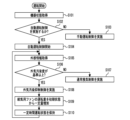
- FIG. 3 shows an example of the operation of the ventilator according to this embodiment.
- the ventilator information acquisition unit 14 acquires the device status.
- the equipment status here includes the operating parameters of the ventilator input to the ventilator input unit 15, the operation signal transmitted from the equipment operation application 102, and the like.
- step S102 the ventilation device control unit 16 determines whether or not to perform automatic operation control based on the device state acquired in step S101. That is, when the operation parameter and the operation signal indicate that automatic operation is set, the ventilator control unit 16 determines to perform automatic operation control. Further, when automatic operation is not set, the ventilator control unit 16 determines not to perform automatic operation control. When not performing automatic operation control, the ventilator control unit 16 next performs the process of step S103.
- step S103 the ventilator control unit 16 performs manual operation control of the ventilator. That is, the ventilator control unit 16 controls the air supply fan 11 and the exhaust fan 12 based on the set value of the ventilation volume input to the ventilator input unit 15 or the device operation application 102 .
- step S104 the ventilator control unit 16 starts automatic operation control.
- the ventilator control unit 16 performs, for example, the above-described first control, that is, normal ventilation control.
- the ventilator control unit 16 controls the air supply fan 11 so that the air supply amount becomes the first air supply amount, and controls the exhaust fan 12 so that the exhaust amount becomes the first exhaust amount. .
- step S105 the ventilator information acquisition unit 14 acquires external information.
- the external information here is the aforementioned external environment data.
- the external environment data includes information (at least one of forecast value and actual value) on the degree of contamination of the outside air.
- the ventilator control unit 16 next performs the process of step S106.
- step S106 the ventilator control unit 16 determines whether or not the degree of contamination of the outside air is equal to or higher than the standard based on the external information acquired in step S105, that is, the external environment data. If the contamination degree of the outside air is not equal to or higher than the standard, the ventilator control unit 16 next performs the process of step S107. In step S107, the ventilator control unit 16 performs the normal ventilation control, that is, the first control described above.
- step S106 if the contamination degree of the outside air is equal to or higher than the standard, the ventilator control unit 16 then performs the process of step S108.
- step S108 the ventilator control unit 16 performs outside air pollution suppression control, that is, the above-described second control. Therefore, in subsequent step S109, the ventilator control unit 16 increases the operation amount of the air supply fan 11 from the initial state by a certain amount.
- the initial state referred to here is the state in which the automatic operation control is started in step S104. As described above, when performing the first control at the start of the automatic operation control, the initial air supply amount is the first air supply amount.
- step S109 the ventilator control unit 16 increases the operating amount of the air supply fan 11 so that the air supply amount increases from the first air supply amount to the second air supply amount. In this example, the operating amount of the exhaust fan 12 is not changed.
- step S109 the ventilator control unit 16 next performs the process of step S110.
- step S110 the ventilator control unit 16 maintains the operating state of step S109 for a predetermined period of time. Then, after a certain period of time has passed, the ventilator returns to step S105 and continues to operate.
- FIG. 4 shows another example of the operation of the ventilator according to this embodiment. Steps S201 to S208 and S210 of FIG. 4 are the same as steps S101 to S108 and S110 of FIG. Therefore, the description of steps S201 to S208 and S210 in FIG. 4 is omitted here to avoid duplication.
- step S209 the ventilator control unit 16 reduces the operation amount of the exhaust fan 12 from the initial state by a certain amount.
- the initial state here is the state in which the automatic operation control is started in step S204.
- the displacement in the initial state is the first displacement. That is, in step S209, the ventilator control unit 16 reduces the operating amount of the exhaust fan 12 so that the exhaust amount decreases from the first exhaust amount to the second exhaust amount. In this example, the operating amount of the air supply fan 11 is not changed.
- step S210 the ventilator control unit 16 then performs the process of step S210.
- the ventilator control unit 16 performs the first control, which is the normal ventilation control, when the degree of contamination of the outside air exceeds a preset standard based on the outside air environment data. to the second control, which is outside air pollution suppression control.
- outside air pollution suppression control the amount of air supply relative to the exhaust amount is increased compared to normal ventilation control. This increases the relative indoor pressure with respect to the outdoor pressure. Therefore, compared to normal ventilation control, outside air pollution suppression control makes it difficult for outside air pollution to flow into the room through gaps such as the ventilation openings 40 of the building 1 . That is, it is possible to efficiently suppress the inflow of outdoor pollution into the room by adjusting the amount of air supply and the amount of exhaust air according to the degree of contamination of the outdoor air. In addition, for this reason, it is possible to ensure the comfort of the people in the room.
- an outdoor air quality sensor that detects outdoor air quality may be further provided.
- the outdoor air quality sensor detects one or more of outdoor air quality such as VOC, odor gas, gas concentration such as carbon dioxide, dust concentration such as dust, and microorganism amount such as virus, mold, and bacteria in the outside air.
- the external environment data acquired by the ventilator information acquisition unit 14 also includes detection data of the outdoor air quality sensor of the environment sensor 103 .
- the ventilator control unit 16 determines whether or not the contamination degree of the outside air is higher than a preset standard, based on the external environment data including the detection data of the outdoor air quality sensor. Therefore, in this case, the ventilator control unit 16 controls the air supply fan 11 and the exhaust fan 12 also according to the detection result of the outdoor air quality sensor.
- an indoor air quality sensor that detects indoor air quality may be further provided.
- the indoor air quality sensor detects the air quality in each room of the building 1 from any of gas concentrations such as VOCs, odorous gases, and carbon dioxide, dust concentrations such as dust, and the amount of microorganisms such as viruses, molds, and bacteria. Detect one or more.
- the ventilator information acquisition unit 14 also acquires the detection data of the indoor air quality sensor of the environment sensor 103 via the ventilator communication unit 13 , the network router 100 and the cloud server 104 . Then, the ventilation device control unit 16 controls the air supply fan 11 and the exhaust fan 12 according to the detection result of the indoor air quality sensor.
- the ventilator control unit 16 determines whether the pollution level of the indoor air is equal to or higher than a preset standard based on the detection result of the indoor air quality sensor. Then, if the degree of contamination of the indoor air is equal to or higher than the standard, the ventilator control unit 16 performs the third control.
- the third control is indoor pollution discharge control.
- the ventilation device control unit 16 causes the air supply amount changing unit to make the exhaust amount of the exhaust unit greater than the air supply amount of the air supply unit. It controls a certain air supply fan 11 and an exhaust fan 12 which is a displacement amount changer. By doing so, indoor contamination can be rapidly discharged to the outdoors.
- the ventilator control unit 16 performs third control, which is indoor pollution discharge control, when the pollution level of the indoor air is equal to or higher than the pollution level of the outdoor air based on the external environment data and the detection result of the indoor air quality sensor. may be performed.
- the ventilator controller 16 of the ventilator main body 10 determines which of the first control and the second control the ventilator performs. However, the determination of whether to perform the first control or the second control may not be made by the ventilator main body 10 .
- the cloud server 104 may have a determination unit that determines which of the first control and the second control should be performed.
- the ventilation device control unit 16 controls the air supply fan 11 and the exhaust fan 12 according to the control details determined by the determination unit of the cloud server 104 . Therefore, in this case, it can be said that the ventilation device control unit 16 and the determining unit of the determining unit of the cloud server 104 constitute a control unit that controls the air supply fan 11 and the exhaust fan 12 .
- FIG. 5 is a cross-sectional view schematically showing the configuration of a building in which a ventilation device and a ventilation system are installed.
- FIG. 6 is a perspective view of a heat exchange element included in the ventilator.
- FIG. 7 is a block diagram showing the configuration of the control system of the ventilator and the ventilation system.
- FIG. 8 is a flow diagram showing an example of the operation of the ventilation system.
- FIG. 9 is a flow chart showing an example of the operation of the air conditioner.
- the ventilator has a heat exchange element in the configuration of Embodiment 1 described above.
- a ventilation system is composed of a ventilation device having a heat exchange element and an air conditioner.
- the ventilation system according to the second embodiment will be described below, focusing on the differences from the first embodiment.
- the configuration whose description is omitted is basically the same as that of the first embodiment.
- the same reference numerals as those used in the description of the first embodiment are attached to the same or corresponding configurations as those of the first embodiment.
- the ventilation system includes a ventilation device body 10 and an air conditioner 30, as shown in FIG.
- the air conditioner 30 can air-condition the interior of the building 1 .
- the air conditioners 30 are installed in the second room 1b and the third room 1c.
- the air conditioner 30, for example, cools or heats air to cool or heat the second room 1b and the second room 1b, which are a plurality of rooms.
- the air conditioner 30 includes an air conditioner indoor unit 31 and an air conditioner outdoor unit 32 . 5, illustration of the air conditioner outdoor unit 32 is omitted.
- the ventilation device main body 10 includes a heat exchange element 19 .
- the heat exchange element 19 is provided inside the housing of the ventilation device main body 10 . Inside the housing of the ventilation device main body 10, the supply air passage 10a and the exhaust air passage 10b are formed so as to cross each other. The heat exchange element 19 is installed at the intersection of the supply air passage 10a and the exhaust air passage 10b.
- the heat exchange element 19 is an element that exchanges heat between the air passing through the supply air passage 10a and the air passing through the exhaust air passage 10b.
- the heat exchange element 19 is configured by alternately laminating flat plate-shaped heat exchange paper 19a and support paper 19b having a corrugated structure.
- the heat exchange paper 19a partitions between the supply air flow path and the exhaust air flow path. Heat is exchanged between the supplied air and the exhausted air through the heat exchange paper 19a.
- the support paper 19b supports the heat exchange paper 19a.
- the plurality of support papers 19b are arranged such that the longitudinal directions of the groove-shaped recesses in the corrugated structure are orthogonal to each other between two adjacent support papers 19b with the heat exchange paper 19a interposed therebetween.
- a plurality of air supply flow paths are formed in parallel between the support paper 19b on one surface side of the heat exchange paper 19a and the one surface of the heat exchange paper 19a.
- a plurality of exhaust flow paths are formed in parallel between the support paper 19b on the side of the other surface of the heat exchange paper 19a and the other surface of the heat exchange paper 19a.
- the air supply channel and the exhaust air channel are perpendicular to each other.
- the supply air contacting one surface of the heat exchange paper 19a and the exhaust air contacting the other surface of the heat exchange paper 19a are not mixed with each other. to exchange heat through That is, the heat of whichever of the supplied air and the exhausted air has the higher temperature moves through the heat exchange paper 19a to the air on the opposite side of the heat exchange paper 19a. In this manner, heat is exchanged between the supply and exhaust air passing through the heat exchange element 19 .
- the air in the room is sucked into the room-side exhaust duct 21 from the indoor exhaust port 23 by the exhaust fan 12 and guided to the exhaust air passage 10b of the ventilator main body 10 .
- the indoor air passes through the heat exchange element 19 .
- fresh outdoor air is guided by the air supply fan 11 through the outside air supply duct 24 to the supply air passage 10 a of the ventilation device main body 10 .
- the outdoor fresh air then passes through the heat exchange element 19 .
- indoor air and outdoor fresh air circulate through the heat exchange element 19 so as to cross each other, and only heat is exchanged through the heat exchange element 19 .
- the air in the room is discharged to the outside through the outside-air-side exhaust duct 25 .
- Outdoor fresh air passes through the indoor air supply duct 20 and is supplied indoors from the indoor air supply port 22 .
- the heat exchange element 19 causes heat exchange between the air passing through the air supply section described above and the air passing through the exhaust section described above.
- the ventilator main body 10 having the heat exchange element 19 heat can be exchanged between cool air during cooling or warm air during heating in the room and fresh air outdoors. can. As a result, the cooling or heating load can be reduced.
- the ventilator main body 10 may include a bypass ventilation section 50 capable of performing air supply by the air supply section and exhaustion by the exhaust section without passing through the heat exchange element 19 .
- a bypass ventilation section 50 capable of performing air supply by the air supply section and exhaustion by the exhaust section without passing through the heat exchange element 19 .
- illustration of the bypass ventilation part 50 is abbreviate
- the bypass ventilation unit 50 has a bypass supply air passage, a bypass exhaust air passage, a bypass switching damper, and the like.
- the bypass air supply air passage is an air passage that communicates from the outside air supply air duct to the indoor air supply duct 20 without passing through the heat exchange element 19 in the housing of the ventilator main body 10 .
- the bypass exhaust air passage is an air passage that communicates from the indoor side exhaust duct to the outside air side exhaust duct 25 without passing through the heat exchange element 19 in the housing of the ventilator main body 10 .
- the bypass switching damper determines whether the air passing through the housing of the ventilation device main body 10 passes through the supply air passage 10a, the exhaust air passage 10b, and the heat exchange element 19, or the bypass air supply passage and the bypass exhaust air passage. It is a damper that switches between
- an outdoor air temperature sensor that detects the outdoor air temperature is further provided as the environment sensor 103 .
- the ventilator controller 16 of the ventilator body 10 controls not only the supply fan 11 and the exhaust fan 12 but also the bypass ventilator 50 .
- Control of the bypass ventilation section 50 is mainly control of the bypass switching damper of the bypass ventilation section 50 .
- the ventilation device control unit 16 switches the bypass switching damper of the bypass ventilation unit 50 according to the outside air temperature detected by the outdoor air temperature sensor of the environment sensor 103 . Specifically, the bypass switching damper of the bypass ventilation unit 50 is switched depending on whether or not the outdoor air temperature is within a preset reference range. If the outdoor temperature is equal to or higher than the upper limit of the reference range, or if the outdoor temperature is equal to or lower than the lower limit of the reference range, the ventilation device control unit 16 determines that the outdoor temperature is not within the preset reference range. do. On the other hand, if the outdoor air temperature is less than the above-described upper limit and exceeds the lower limit, the ventilator control unit 16 determines that the outdoor air temperature is within a preset reference range.
- the ventilator control unit 16 switches the bypass switching damper of the bypass ventilation unit 50 so that the heat exchange element 19 performs heat exchange.
- the ventilator control unit 16 switches the bypass switching damper of the bypass ventilation unit 50 so that heat exchange by the heat exchange element 19 is not performed.
- the ventilator control unit 16 switches the bypass switching damper of the bypass ventilation unit 50 according to the current season. That is, when the current season is summer or winter, the ventilation device control unit 16 switches the bypass switching damper of the bypass ventilation unit 50 so that heat exchange is performed by the heat exchange element 19 . Also, when the current season is spring or autumn, that is, the middle season, the ventilation system control unit 16 switches the bypass switching damper of the bypass ventilation unit 50 so that heat exchange by the heat exchange element 19 is not performed.
- the current season may be determined, for example, by the user operating the air conditioner input unit 35 or the like to input a schedule, or by acquiring information on the current date from the cloud server 104 or the like. may
- the air conditioner 30 includes an air conditioner communication unit 33, an air conditioner information acquisition unit 34, an air conditioner input unit 35, an air conditioner control unit 36, and an air conditioner output unit 37.
- the air conditioner input unit 35 is provided as an operation panel of the air conditioner 30, for example.
- the air conditioner input unit 35 is for inputting parameters and the like relating to the operation of the air conditioner 30 by user's operation.
- the operation panel may be provided with a display section for displaying various information related to the air conditioner 30 .
- the display section of the operation panel is, for example, a liquid crystal display.
- a touch panel that serves as the air conditioner input section 35 and the display section may be provided.
- the air conditioner input unit 35 may be provided as a remote controller in each room.
- the air conditioner 30 has, as hardware, for example, a computer with a processor and memory.
- a processor is also called a CPU (Central Processing Unit), a central processing unit, a processing unit, an arithmetic unit, a microprocessor, a microcomputer, or a DSP.
- the memory includes, for example, non-volatile or volatile semiconductor memory such as RAM, ROM, flash memory, EPROM and EEPROM, magnetic disk, flexible disk, optical disk, compact disk, mini-disk and DVD.
- a program as software is stored in the memory of the air conditioner 30 . Then, the air conditioner 30 executes a preset process by causing the processor to execute the program stored in the memory, and as a result of cooperation between the hardware and software, the air conditioner communication unit 33 described below , an air conditioner information acquisition unit 34 , an air conditioner control unit 36 and an air conditioner output unit 37 .
- the circuit of the air conditioner 30 may be formed as dedicated hardware, for example.
- a part of the circuit of the air conditioner 30 may be formed as dedicated hardware, and the circuit may include a processor and a memory.
- Circuits partly formed as dedicated hardware include, for example, single circuits, multiple circuits, programmed processors, parallel programmed processors, ASICs, FPGAs, or combinations thereof.
- the air conditioner communication unit 33 transmits and receives various types of information via a communication network or the like.
- the air conditioner 30 can transmit and receive various information to and from the outside of the air conditioner 30 via the air conditioner communication unit 33 .
- the communication at this time may be performed by wire or wirelessly, and any communication protocol may be used as long as mutual communication can be performed.
- the air conditioner communication unit 33 is provided to communicate with the cloud server 104 via the network router 100 .
- the cloud server 104 aggregates information from the weather information server 101, the device operation application 102, the environment sensor 103, and the like, and provides a service of transmitting the aggregated information. Furthermore, the cloud server 104 provides a service for the cooperative operation of the ventilation device body 10 and the air conditioner 30 .
- the ventilator main body 10 transmits information indicating whether the current control content is the above-described first control or second control from the ventilator communication unit 13 to the cloud server 104 .
- the cloud server 104 transmits information about the current control details of the ventilation device main body 10 to the air conditioner 30 .
- the air conditioner communication unit 33 receives information about the current control details of the ventilation device body 10 transmitted from the cloud server 104 .
- the air conditioner information acquisition unit 34 acquires information about the current control content of the ventilation device body 10 received by the air conditioner communication unit 33 .
- the air conditioner information acquisition unit 34 also acquires information input to the air conditioner input unit 35 .
- the air conditioner control unit 36 determines the operation control details of the air conditioner 30 based on the information acquired by the air conditioner information acquisition unit 34 . Specifically, the air conditioner control unit 36 determines the operation details and the like of the air conditioner indoor unit 31 and the air conditioner outdoor unit 32 .
- the operation contents of the air conditioner indoor unit 31 are, for example, the direction and the amount of air blowing from the air conditioner indoor unit 31 .
- the operation content of the air conditioner outdoor unit 32 is, for example, the operation of the compressor.
- the air conditioner output unit 37 generates a control signal of the control content determined by the air conditioner control unit 36 and outputs the control signal to the air conditioner indoor unit 31 and the air conditioner outdoor unit 32 .
- the air conditioner indoor unit 31 and the air conditioner outdoor unit 32 operate according to the control signal output from the air conditioner output unit 37 . In this manner, the air conditioner controller 36 controls the air conditioner indoor unit 31 and the air conditioner outdoor unit 32 .
- the air conditioner 30 can perform the linked air conditioning operation.
- the linked air conditioning operation is the operation of the air conditioner 30 that is performed in conjunction with the outside air pollution suppression control of the ventilation device main body 10 when the ventilation device main body 10 is performing the above-described second control, that is, the outside air pollution suppression control. be.
- the air conditioner information acquisition unit 34 acquires information regarding the current control details of the ventilation device main body 10 . Then, when the current control content of the ventilation device main body 10 is outside air pollution suppression control, the air conditioner control unit 36 controls the air conditioner indoor unit 31 and the air conditioner outdoor unit 32 to cause the air conditioner 30 to perform interlocking air conditioning operation. let it happen In the interlocked air conditioning operation, the operability of the air conditioner 30 is enhanced. That is, when the air conditioner 30 is in the cooling operation, the air conditioner control unit 36 controls the air conditioner indoor unit 31 and the air conditioner to lower the set temperature for the cooling operation, increase the air volume, or both. It controls the outdoor unit 32 . In addition, when the air conditioner 30 is in the heating operation, the air conditioner control unit 36 increases the set temperature for the heating operation, increases the air volume, or both. It controls the outdoor unit 32 .
- the air supply amount and exhaust amount are adjusted according to the degree of contamination of the outdoor air, and the inflow of outdoor pollution into the room is efficiently prevented. can be suppressed to Also, in outside air pollution suppression control, the amount of supplied air relative to the exhaust amount is increased compared to normal ventilation control. Therefore, when the amount of outside air flowing into the room increases and the temperature, humidity, etc. of the room are easily affected by the outside air, the influence of the outside air can be reduced by performing the interlocking air conditioning operation of the air conditioner 30 . Therefore, it is possible to efficiently suppress the inflow of outdoor pollution into the room while suppressing deterioration of indoor thermal comfort.
- the air conditioner control unit 36 may perform interlocking air conditioning operation according to the outdoor air temperature in addition to the control contents of the ventilation device main body 10.
- the air conditioner control unit 36 further determines that the outside air temperature detected by the outside air temperature sensor of the environment sensor 103 is within the above-described reference range. It is determined whether or not there is Then, if the outside air temperature is not within the reference range, the air conditioner control unit 36 causes the air conditioner 30 to perform the linked air conditioning operation.
- the air conditioner control unit 36 does not allow the air conditioner 30 to perform the linked air conditioning operation. In this case, when the ventilator performs the second control, the air conditioner 30 performs the linked air conditioning operation when the outdoor temperature is not within the preset reference range.
- the interlocked air conditioning operation is performed to suppress an increase in the power consumption of the air conditioner 30, suppress a decrease in thermal comfort, and prevent pollution. can be compatible with the suppression of the inflow of air into the room.
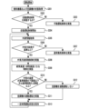
- FIG. 8 shows an example of the operation of the ventilation system according to this embodiment.
- the ventilator information acquisition unit 14 acquires the state of the ventilator main body 10 .
- the air conditioner information acquisition unit 34 acquires the state of the air conditioner 30 .
- the state of the ventilator body 10 here includes the operation parameters of the ventilator input to the ventilator input unit 15, the operation signal transmitted from the device operation application 102, and the like.
- the state of the air conditioner 30 here includes the operation parameters of the air conditioner 30 input to the air conditioner input unit 35, the operation signal transmitted from the device operation application 102, and the like.
- the ventilator control unit 16 determines whether or not to perform automatic operation control based on the device status acquired in step S301. That is, when the operation parameter and the operation signal indicate that automatic operation is set, the ventilator control unit 16 determines to perform automatic operation control. Further, when automatic operation is not set, the ventilator control unit 16 determines not to perform automatic operation control. When the automatic operation control is not performed, the ventilator control unit 16 next performs the process of step S303.
- step S303 the ventilator control unit 16 performs manual operation control of the ventilator. That is, the ventilator control unit 16 controls the air supply fan 11 and the exhaust fan 12 based on the set value of the ventilation volume input to the ventilator input unit 15 or the device operation application 102 .
- step S304 the ventilator control unit 16 starts automatic operation control.
- the ventilator control unit 16 performs, for example, the above-described first control, that is, normal ventilation control.
- the ventilator control unit 16 controls the air supply fan 11 so that the air supply amount becomes the first air supply amount, and controls the exhaust fan 12 so that the exhaust amount becomes the first exhaust amount. .
- the ventilator information acquisition unit 14 acquires external information.
- the external information here is the aforementioned external environment data.
- the external environment data includes information (at least one of forecast value and actual value) on the degree of contamination of the outside air.
- the air conditioner information acquisition unit 34 acquires the outdoor temperature detected by the outdoor temperature sensor of the environment sensor 103 .
- the ventilator control unit 16 next performs the process of step S306.
- step S306 the ventilator control unit 16 determines whether or not the contamination level of the outside air is equal to or higher than the standard, based on the external information acquired in step S305, that is, the external environment data. If the contamination degree of the outside air is not equal to or higher than the standard, the ventilator control unit 16 next performs the process of step S307. In step S307, the ventilator control unit 16 performs the normal ventilation control, that is, the first control described above.
- step S306 if the contamination level of the outside air is equal to or higher than the standard, the ventilator control unit 16 then performs the process of step S308.
- step S308 the ventilator control unit 16 performs outside air pollution suppression control, that is, the above-described second control.
- the ventilator control unit 16 controls one or both of the air supply fan 11 and the exhaust fan 12 so that the amount of air supplied is greater than the amount of exhaust air.
- the ventilator control unit 16 increases the operation amount of the air supply fan 11 from the initial state by a certain amount, or decreases the operation amount of the exhaust fan 12 from the initial state by a certain amount, or both.
- step S310 the air conditioner control unit 36 determines whether the outside air temperature acquired in step S305 is within the above-described reference range. That is, the air conditioner control unit 36 determines whether the outside air temperature is equal to or higher than the upper limit value of the reference range or equal to or lower than the lower limit value of the reference range. If the outside temperature is equal to or higher than the upper limit value of the reference range or equal to or lower than the lower limit value of the reference range, that is, if the outside temperature is not within the reference range, then the air conditioner control section 36 performs the process of step S311.
- step S311 the air conditioner control unit 36 controls the air conditioner 30 to perform the linked air conditioning operation described above.
- the air conditioner control unit 36 then performs the process of step S312. I do.
- step S312 the air conditioner 30 does not perform the interlocked air conditioning operation described above.
- the ventilator control unit 16 and the air conditioner control unit 36 perform the process of step S313.
- step S313 the ventilator control unit 16 maintains the operating state of step S309 for a predetermined period of time.
- the air conditioner control unit 36 maintains the operating state of step S311 or S312 for a predetermined period of time. Then, after a certain period of time has elapsed, the ventilator and air conditioner 30 return to step S305 to continue operation.
- step S401 the air conditioner information acquiring unit 34 acquires the operating state of the air conditioner 30.
- step S402 the air conditioner control unit 36 determines whether or not the air conditioner 30 is in operation based on the operating state of the air conditioner 30 acquired in step S401.
- step S407 the air conditioner control unit 36 controls the air conditioner indoor unit 31 and the air conditioner outdoor unit 32 to enhance the operability of the air conditioner 30 .
- step S402 the air conditioner control unit 36 then performs the processing of step S403.
- step S403 the air conditioner control unit 36 causes the air conditioner 30 to start operating.
- step S404 the air conditioner control unit 36 determines whether or not the outside air temperature is equal to or higher than the upper limit value of the reference range described above.
- the air conditioner control unit 36 When the outside air temperature is equal to or higher than the upper limit of the reference range, the air conditioner control unit 36 then performs the process of step S405. In this case, since the outside air temperature is high, the air conditioner control unit 36 controls the air conditioner indoor unit 31 and the air conditioner outdoor unit 32 so that the air conditioner 30 performs cooling operation in step S405.
- step S404 if the outside air temperature is not equal to or higher than the upper limit value of the reference range in step S404, then the air conditioner control unit 36 performs the processing of step S406. In this case, the outside air temperature is below the lower limit of the reference range. Therefore, since the outside air temperature is low, the air conditioner control unit 36 controls the air conditioner indoor unit 31 and the air conditioner outdoor unit 32 so that the air conditioner 30 performs the heating operation in step S406.
- the cloud server 104 may determine the control details of the ventilation device main body 10 and the air conditioner 30 .
- the ventilator main body 10 may not include the heat exchange element 19 .
- the ventilation system includes a ventilation device main body 10 having no heat exchange element 19 and an air conditioner 30 .
- the present disclosure can be used for a ventilation system that performs Type 1 ventilation in which both air supply and exhaust are performed by mechanical ventilation, and a ventilation system that includes a ventilation system and an air conditioner that perform Type 1 ventilation.
Landscapes
- Engineering & Computer Science (AREA)
- Chemical & Material Sciences (AREA)
- Combustion & Propulsion (AREA)
- Mechanical Engineering (AREA)
- General Engineering & Computer Science (AREA)
- Physics & Mathematics (AREA)
- Fluid Mechanics (AREA)
- Ventilation (AREA)
Priority Applications (4)
| Application Number | Priority Date | Filing Date | Title |
|---|---|---|---|
| EP21959263.1A EP4411267A4 (en) | 2021-09-28 | 2021-09-28 | Ventilation device and ventilation system |
| JP2023550800A JP7643576B2 (ja) | 2021-09-28 | 2021-09-28 | 換気装置及び換気システム |
| PCT/JP2021/035677 WO2023053215A1 (ja) | 2021-09-28 | 2021-09-28 | 換気装置及び換気システム |
| CN202180102540.9A CN117980663A (zh) | 2021-09-28 | 2021-09-28 | 换气装置和换气系统 |
Applications Claiming Priority (1)
| Application Number | Priority Date | Filing Date | Title |
|---|---|---|---|
| PCT/JP2021/035677 WO2023053215A1 (ja) | 2021-09-28 | 2021-09-28 | 換気装置及び換気システム |
Publications (1)
| Publication Number | Publication Date |
|---|---|
| WO2023053215A1 true WO2023053215A1 (ja) | 2023-04-06 |
Family
ID=85781505
Family Applications (1)
| Application Number | Title | Priority Date | Filing Date |
|---|---|---|---|
| PCT/JP2021/035677 Ceased WO2023053215A1 (ja) | 2021-09-28 | 2021-09-28 | 換気装置及び換気システム |
Country Status (4)
| Country | Link |
|---|---|
| EP (1) | EP4411267A4 (https=) |
| JP (1) | JP7643576B2 (https=) |
| CN (1) | CN117980663A (https=) |
| WO (1) | WO2023053215A1 (https=) |
Families Citing this family (2)
| Publication number | Priority date | Publication date | Assignee | Title |
|---|---|---|---|---|
| WO2023144886A1 (ja) * | 2022-01-25 | 2023-08-03 | 三菱電機株式会社 | 換気装置 |
| JP7846385B2 (ja) * | 2023-09-29 | 2026-04-15 | ダイキン工業株式会社 | 空調システム |
Citations (4)
| Publication number | Priority date | Publication date | Assignee | Title |
|---|---|---|---|---|
| JP2013113473A (ja) * | 2011-11-28 | 2013-06-10 | Mitsubishi Electric Corp | 熱交換換気装置 |
| JP2015190687A (ja) * | 2014-03-28 | 2015-11-02 | パナソニックIpマネジメント株式会社 | 換気装置 |
| JP2018044751A (ja) * | 2016-09-16 | 2018-03-22 | 日立アプライアンス株式会社 | 電気機器制御システム |
| US20210063036A1 (en) * | 2019-08-29 | 2021-03-04 | Lg Electronics Inc. | Air purifier and operating method of the same |
Family Cites Families (4)
| Publication number | Priority date | Publication date | Assignee | Title |
|---|---|---|---|---|
| CN106016562B (zh) * | 2016-05-18 | 2019-04-30 | 青岛海信日立空调系统有限公司 | 一种控制方法、通风装置及空调系统 |
| WO2018061147A1 (ja) * | 2016-09-29 | 2018-04-05 | 三菱電機株式会社 | 換気システム |
| JP7209143B2 (ja) | 2018-08-30 | 2023-01-20 | パナソニックIpマネジメント株式会社 | 熱交換型換気扇 |
| KR102167857B1 (ko) * | 2019-01-28 | 2020-10-20 | 백창인 | 폐열회수형 환기장치 시스템 |
-
2021
- 2021-09-28 EP EP21959263.1A patent/EP4411267A4/en not_active Withdrawn
- 2021-09-28 WO PCT/JP2021/035677 patent/WO2023053215A1/ja not_active Ceased
- 2021-09-28 JP JP2023550800A patent/JP7643576B2/ja active Active
- 2021-09-28 CN CN202180102540.9A patent/CN117980663A/zh active Pending
Patent Citations (4)
| Publication number | Priority date | Publication date | Assignee | Title |
|---|---|---|---|---|
| JP2013113473A (ja) * | 2011-11-28 | 2013-06-10 | Mitsubishi Electric Corp | 熱交換換気装置 |
| JP2015190687A (ja) * | 2014-03-28 | 2015-11-02 | パナソニックIpマネジメント株式会社 | 換気装置 |
| JP2018044751A (ja) * | 2016-09-16 | 2018-03-22 | 日立アプライアンス株式会社 | 電気機器制御システム |
| US20210063036A1 (en) * | 2019-08-29 | 2021-03-04 | Lg Electronics Inc. | Air purifier and operating method of the same |
Non-Patent Citations (1)
| Title |
|---|
| See also references of EP4411267A4 * |
Also Published As
| Publication number | Publication date |
|---|---|
| JP7643576B2 (ja) | 2025-03-11 |
| EP4411267A1 (en) | 2024-08-07 |
| CN117980663A (zh) | 2024-05-03 |
| JPWO2023053215A1 (https=) | 2023-04-06 |
| EP4411267A4 (en) | 2024-12-25 |
Similar Documents
| Publication | Publication Date | Title |
|---|---|---|
| CN107131567B (zh) | 空气净化系统及其控制方法 | |
| JP6120820B2 (ja) | 換気システム | |
| CN205579772U (zh) | 空气净化系统 | |
| JP5460673B2 (ja) | 換気装置及び換気システム | |
| KR20180014122A (ko) | 환기장치 | |
| CN204494652U (zh) | 空气净化器 | |
| JP7643576B2 (ja) | 換気装置及び換気システム | |
| JP5538342B2 (ja) | 換気装置及び換気システム | |
| JP2021177111A (ja) | 空調システム | |
| WO2019035194A1 (ja) | 熱交換換気装置 | |
| JP5263111B2 (ja) | 換気装置 | |
| WO2007123144A1 (ja) | 換気システム | |
| JP2002089940A (ja) | 空気調和機 | |
| JP2020046170A (ja) | 空気調和システム | |
| JP7336630B2 (ja) | 換気システム | |
| JP4451766B2 (ja) | 換気機能付き空気調和機及び全館換気空調装置 | |
| JP3723167B2 (ja) | 空調用室内ユニットおよびこれを備えた空気調和機 | |
| JP2021196095A (ja) | 空調装置及び換気空調システム | |
| JP2001201134A (ja) | 熱交換換気装置 | |
| KR200416876Y1 (ko) | 쾌적한 실내환경을 가능하게 하는 쾌적제어시스템 | |
| JP7630635B2 (ja) | 換気制御システム | |
| JP2014066400A (ja) | 熱交換機器 | |
| WO2019058516A1 (ja) | 熱交換型換気装置 | |
| CN110131878A (zh) | 一种多功能空调机组 | |
| JP2025184581A (ja) | 空調システム |
Legal Events
| Date | Code | Title | Description |
|---|---|---|---|
| 121 | Ep: the epo has been informed by wipo that ep was designated in this application |
Ref document number: 21959263 Country of ref document: EP Kind code of ref document: A1 |
|
| WWE | Wipo information: entry into national phase |
Ref document number: 2023550800 Country of ref document: JP |
|
| WWE | Wipo information: entry into national phase |
Ref document number: 202180102540.9 Country of ref document: CN |
|
| NENP | Non-entry into the national phase |
Ref country code: DE |
|
| ENP | Entry into the national phase |
Ref document number: 2021959263 Country of ref document: EP Effective date: 20240429 |