WO2023053192A1 - ロープ及びその製造方法 - Google Patents
ロープ及びその製造方法 Download PDFInfo
- Publication number
- WO2023053192A1 WO2023053192A1 PCT/JP2021/035613 JP2021035613W WO2023053192A1 WO 2023053192 A1 WO2023053192 A1 WO 2023053192A1 JP 2021035613 W JP2021035613 W JP 2021035613W WO 2023053192 A1 WO2023053192 A1 WO 2023053192A1
- Authority
- WO
- WIPO (PCT)
- Prior art keywords
- core
- rope
- filaments
- strands
- strand
- Prior art date
- Legal status (The legal status is an assumption and is not a legal conclusion. Google has not performed a legal analysis and makes no representation as to the accuracy of the status listed.)
- Ceased
Links
Images


Classifications
-
- D—TEXTILES; PAPER
- D07—ROPES; CABLES OTHER THAN ELECTRIC
- D07B—ROPES OR CABLES IN GENERAL
- D07B1/00—Constructional features of ropes or cables
- D07B1/02—Ropes built-up from fibrous or filamentary material, e.g. of vegetable origin, of animal origin, regenerated cellulose, plastics
-
- D—TEXTILES; PAPER
- D07—ROPES; CABLES OTHER THAN ELECTRIC
- D07B—ROPES OR CABLES IN GENERAL
- D07B1/00—Constructional features of ropes or cables
- D07B1/06—Ropes or cables built-up from metal wires, e.g. of section wires around a hemp core
-
- D—TEXTILES; PAPER
- D07—ROPES; CABLES OTHER THAN ELECTRIC
- D07B—ROPES OR CABLES IN GENERAL
- D07B1/00—Constructional features of ropes or cables
- D07B1/16—Ropes or cables with an enveloping sheathing or inlays of rubber or plastics
-
- B—PERFORMING OPERATIONS; TRANSPORTING
- B66—HOISTING; LIFTING; HAULING
- B66B—ELEVATORS; ESCALATORS OR MOVING WALKWAYS
- B66B7/00—Other common features of elevators
- B66B7/06—Arrangements of ropes or cables
Definitions
- the present disclosure relates to a rope and its manufacturing method.
- the core rope is constructed by twisting together a plurality of core rope strands.
- Each core strand has multiple yarns.
- Each yarn is composed of a blend of monofilaments and multifilaments (see, for example, Patent Document 1).
- the present disclosure has been made to solve the above problems, and aims to obtain a rope and a method for manufacturing the same that can reduce the gap in the core rope and suppress unnecessary elongation. .
- a rope according to the present disclosure includes a core rope and a plurality of steel strands twisted around the outer circumference of the core rope, the core rope being configured by twisting the core rope strands together,
- Each core strand has a plurality of first synthetic filaments and a plurality of second synthetic filaments, each second filament having a diameter greater than the diameter of each first filament.
- Each first filament is surrounded by a plurality of second filaments.
- a plurality of second filaments made of synthetic fibers having a diameter smaller than that of the first filaments are twisted around the outer periphery of the first filaments made of synthetic fibers to manufacture small strands.
- a step of twisting a plurality of small strands together to produce a core rope strand a step of twisting a plurality of core strands together to produce a core rope; and a plurality of steel strands around the core rope. including the step of twisting the
- FIG. 1 is a side view showing an elevator according to Embodiment 1;
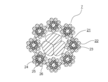
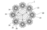
- FIG. Figure 2 is a cross-sectional view of the main rope of Figure 1;
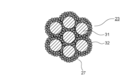
- 3 is an enlarged cross-sectional view showing the core strand of FIG. 2;
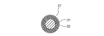
- FIG. FIG. 4 is a cross-sectional view showing the state of the small strand of FIG. 3 immediately after production;
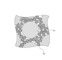
- 4 is a cross-sectional view showing an enlarged part of the core strand of FIG. 3;
- FIG. FIG. 4 is a cross-sectional view showing an enlarged part of a core strand according to a first comparative example;
- FIG. 11 is a cross-sectional view showing an enlarged part of a core strand according to a second comparative example;
- FIG. 11 is a cross-sectional view showing an enlarged part of a core strand according to a third comparative example;
- FIG. 4 is a cross-sectional view showing a first modification of the main rope of Embodiment 1;
- FIG. 5 is a cross-sectional view showing a second modification of the main rope of Embodiment 1;
- FIG. 5 is a cross-sectional view of a main rope according to Embodiment 2;
- FIG. 8 is a cross-sectional view of a main rope according to Embodiment 3;
- Embodiment 1. 1 is a side view showing an elevator according to Embodiment 1.
- FIG. 1 a machine room 2 is provided above the hoistway 1 .
- a hoist 3 and a deflector 6 are installed in the machine room 2 .
- the hoisting machine 3 has a hoisting machine main body 4 and a drive sheave 5 .
- the hoist main body 4 has a hoist motor (not shown) and a hoist brake (not shown).
- the hoist motor rotates the drive sheave 5 .
- the hoist brake keeps the drive sheave 5 stationary. Also, the hoist brake brakes the rotation of the drive sheave 5 .
- a plurality of main ropes 7 are wound around the drive sheave 5 and the deflector wheel 6 .
- Each of the plurality of main ropes 7 is an elevator rope.
- the car 8 and the counterweight 9 are suspended in the hoistway 1 by a plurality of main ropes 7. Further, the car 8 and the counterweight 9 move up and down in the hoistway 1 by rotating the drive sheave 5 .
- a pair of car guide rails 10 and a pair of counterweight guide rails 11 are installed in the hoistway 1 .
- FIG. 1 only one car guide rail 10 and one counterweight guide rail 11 are shown.
- a pair of car guide rails 10 guides the rise and fall of the car 8.
- a pair of counterweight guide rails 11 guide the lifting and lowering of the counterweight 9 .
- the car 8 has a car frame 12 and a car room 13. A plurality of main ropes 7 are connected to the car frame 12 .
- the car room 13 is supported by the car frame 12 .
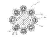
- FIG. 2 is a cross-sectional view of the main rope 7 of FIG. 1, showing a cross section perpendicular to the length direction of the main rope 7.
- the main rope 7 of Embodiment 1 is an 8 ⁇ S(19) type rope conforming to JIS G 3525.
- the main rope 7 has a core rope 21 and a plurality of steel strands 22. In this example, eight steel strands 22 are twisted around the core rope 21 .
- the core rope 21 is arranged at the center of the cross section perpendicular to the length direction of the main rope 7 .
- the core rope 21 is constructed by twisting a plurality of core rope strands 23 together. In this example, three core strands 23 are used. That is, the core rope 21 of Embodiment 1 is a so-called three-strand rope.
- the core 21 may be impregnated with grease or oil.
- Each steel strand 22 has a plurality of steel strands.
- the plurality of steel strands includes a center strand 24, a plurality of intermediate strands 25, and a plurality of outer layer strands 26. As shown in FIG.
- the center strand 24 is arranged at the center of the cross section perpendicular to the length direction of the steel strand 22 .
- a plurality of intermediate strands 25 are twisted around the center strand 24 . In this example, nine intermediate strands 25 are used.
- a plurality of outer layer strands 26 are twisted around the outer periphery of an intermediate layer composed of a plurality of intermediate strands 25 .
- nine outer layer strands 26 are used. That is, in each steel strand 22, the number of intermediate strands 25 and the number of outer layer strands 26 are the same.
- each outer layer wire 26 is smaller than the diameter of the central wire 24 .
- the diameter of each intermediate strand 25 is smaller than the diameter of each outer layer strand 26 .
- each steel strand 22 is pressed against the outer circumference of the core rope 21 .
- FIG. 3 is an enlarged cross-sectional view showing the core strand 23 of FIG.
- Each core strand 23 has a plurality of first synthetic filaments 31 and a plurality of second synthetic filaments 32 .
- each second filament 32 is smaller than the diameter of each first filament 31 . Conversely, the diameter of each first filament 31 is larger than the diameter of each second filament 32 .
- d1/d2 is preferably 2 or more. Further, d1/d2 is more preferably 3 or more and 5 or less.
- each first filament 31 is surrounded by a plurality of second filaments 32 .
- a plurality of second filaments 32 are interposed between adjacent first filaments 31 .
- a first synthetic fiber is used as the material of each first filament 31 .
- a second synthetic fiber is used as the material of each second filament 32 .
- the second synthetic fiber is preferably selected in consideration of wear resistance against contact with the steel strand 22 and rubbing. For this reason, as the second synthetic fiber, for example, polyester fiber, particularly polyethylene terephthalate (PET) fiber is preferable.
- PET polyethylene terephthalate
- the first synthetic fiber may be the same material as the second synthetic fiber, or may be a different material from the second synthetic fiber.
- a polyethylene terephthalate filament with a diameter of 100 ⁇ m can be used as the first filament 31 and a polyethylene terephthalate filament with a diameter of 30 ⁇ m can be used as the second filament 32 .
- d1/d2 is approximately 3.3.
- d1/d2 is smaller than 2, there is a possibility that the plurality of second filaments 32 will not sufficiently enter between the adjacent first filaments 31 .
- d1/d2 is not necessarily limited to 2 or more.
- Each core strand 23 is constructed by twisting a plurality of small strands 27 together. In this example, seven small strands 27 are used.
- Each small strand 27 has one first filament 31 and multiple second filaments 32 .
- a plurality of second filaments 32 are twisted around the circumference of the first filament 31 .
- the manufacturing method of the main rope 7 of Embodiment 1 includes a small strand manufacturing process, a core strand manufacturing process, a core rope manufacturing process, and a process of twisting a plurality of steel strands 22 around the outer circumference of the core rope 21.
- the small strand manufacturing process is a process of manufacturing the small strand 27 by twisting a plurality of second filaments 32 around the outer periphery of the first filament 31 .
- FIG. 4 is a cross-sectional view showing the state of the small strand 27 of FIG. 3 immediately after production.
- a plurality of second filaments 32 are evenly twisted around the outer periphery of the first filament 31 .
- the core strand manufacturing process is a process of twisting together a plurality of small strands 27 to manufacture the core strand 23 .
- the core rope manufacturing process is a process of twisting together a plurality of core rope strands 23 to manufacture the core rope 21 .
- the main rope 7 is manufactured by twisting a plurality of steel strands 22 around the outer circumference of the core rope 21 .
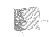
- FIG. 5 is a cross-sectional view showing an enlarged part of the core strand 23 of FIG. Since a plurality of second filaments 32 are twisted around each first filament 31, even if a plurality of small strands 27 are twisted together, the plurality of second filaments 32 are less likely to come apart. Therefore, a state in which each first filament 31 is surrounded by a plurality of second filaments 32 can be realized more reliably.
- FIG. 6 is a cross-sectional view showing an enlarged part of the core strand according to the first comparative example.
- the core strand according to the first comparative example is composed only of the plurality of first filaments 31 .
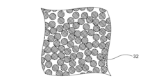
- FIG. 7 is a cross-sectional view showing an enlarged part of the core strand according to the second comparative example.
- the core strand according to the second comparative example is composed only of the plurality of second filaments 32 .
- the number of gaps is small, but the size of each gap is large.
- the size of each gap is small, but the number of gaps is large.
- the diameter of each second filament 32 is smaller than the diameter of each first filament 31 .
- a plurality of second filaments 32 are inserted between adjacent first filaments 31 . Therefore, the gap in the core strand 23 can be significantly reduced.
- FIG. 8 is a cross-sectional view showing an enlarged part of the core strand according to the third comparative example.
- the core strand according to the third comparative example has a plurality of first yarns and a plurality of second yarns. Each first yarn is configured by bundling a plurality of first filaments 31 . Each second yarn is configured by bundling a plurality of second filaments 32 .
- the total amount of gaps is the same as in the first comparative example and the second comparative example.
- each second filament 32 is smaller than the diameter of each first filament 31 .
- the outer circumference of each first filament 31 is surrounded by a plurality of second filaments 32 .
- the small strands 27 are manufactured by twisting a plurality of second filaments 32 around the outer circumference of the first filament 31 .
- the gap in the core rope 21 can be reduced, and when the core rope 21 receives compressive force from the plurality of steel strands 22, the reduction in the diameter of the core rope 21 is suppressed. . Therefore, unnecessary elongation of the main rope 7 can be suppressed. Also, the life of the main rope 7 can be extended.
- vibration of the car 8 when a user gets on and off the car 8 can be suppressed.
- a plurality of second filaments 32 are twisted around the outer periphery of each first filament 31 . Therefore, the separation of the plurality of second filaments 32 from the outer periphery of each first filament 31 during the manufacture of the core strand 23 is suppressed. Thereby, the gap in the core rope 21 can be reduced more reliably.
- a plurality of second filaments 32 are interposed between adjacent first filaments 31 . Therefore, adjacent first filaments 31 are not in direct contact with each other. Therefore, the gap in the core rope 21 can be reduced more reliably.
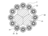
- FIG. 9 is a cross-sectional view showing a first modification of the main rope 7 of Embodiment 1.
- FIG. 9 is a cross-sectional view showing a first modification of the main rope 7 of Embodiment 1.
- each steel strand 22 is compressed from the outside in the radial direction so that the cross-sectional shape of each steel strand 22 perpendicular to the length direction is circular. That is, the cross-sectional shape of each steel strand 22 is deformed.
- the number of core strands 23 included in the core 21 is not limited to three.
- the number of steel strands 22 is not limited to eight.
- FIG. 10 is a cross-sectional view showing a second modification of the main rope 7 of Embodiment 1.
- FIG. 10 in a second variant, twelve steel strands 22 are used. Also, the cross-sectional shape of each steel strand 22 is deformed as in the first modification.
- FIG. 11 is a cross-sectional view of the main rope 7 according to Embodiment 2, showing a cross section perpendicular to the length direction of the main rope 7.
- the core cord 21 of Embodiment 2 has a central strand 33 and a plurality of outer strands 34 in addition to the core cord strands 23 .
- the center strand 33 is arranged at the center of the core rope 21 in a cross section perpendicular to the length direction of the core rope 21 .
- Each outer perimeter strand 34 is arranged between adjacent core strands 23 on the outer periphery of the core 21 .
- the number of outer strands 34 is the same as the number of core strands 23 .
- three outer strands 34 are used for three core strands 23 .
- a synthetic fiber twisted yarn can be used as the central strand 33 .
- a strand having a cross-sectional configuration similar to that of the small strands 27 shown in FIG. 4 can be used after appropriately adjusting the diameter.
- a strand similar to the center strand 33 can be used as each outer strand 34 .
- the central gap of the core rope 21 is filled with the central strand 33. Therefore, the gap in the core rope 21 can be further reduced, and unnecessary elongation of the main rope 7 can be suppressed more reliably.
- Either one of the central strand 33 and the plurality of outer peripheral strands 34 may be omitted.
- At least one of the central strand 33 and the plurality of outer peripheral strands 34 may be provided in the main rope 7 of the first modified example shown in FIG.
- At least one of the central strand 33 and the plurality of outer peripheral strands 34 may be provided in the main rope 7 of the second modified example shown in FIG.
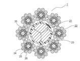
- FIG. 12 is a cross-sectional view of the main rope 7 according to Embodiment 3, showing a cross section perpendicular to the length direction of the main rope 7.
- the main rope 7 of Embodiment 3 has a core coating 35 in addition to the core 21 and the plurality of steel strands 22 .
- a core wire coating 35 covers the outer circumference of the core wire 21 . That is, the core coating 35 is interposed between the core 21 and the plurality of steel strands 22 .
- resin or rubber can be used as a material for the cord coating 35.
- resin or rubber can be used as a material for the cord coating 35.
- polyethylene, polypropylene, polyvinyl chloride, polyamide, or polyurethane elastomer can be used as the material of the core coating 35, for example.
- the core wire coating 35 is provided on the outer circumference of the core wire 21 by a manufacturing process similar to that for coating cables. That is, the core wire coating 35 is applied to the outer periphery of the core wire 21 by extrusion coating the core wire 21 through the center.
- the core rope 21 does not come into direct contact with the plurality of steel strands 22, wear and damage to the core rope 21 can be suppressed.
- At least one of the central strand 33 and the plurality of outer peripheral strands 34 shown in the second embodiment may be provided in the main rope 7 of the third embodiment.
- a core cord coating 35 may be provided on the main rope 7 of the first modified example shown in FIG.
- the main rope 7 of the first modified example may be provided with the core coating 35 and at least one of the central strand 33 and the plurality of outer strands 34 .
- the main rope 7 of the second modification shown in FIG. 10 may be provided with a core cord coating 35 .
- the main rope 7 of the second modification may be provided with the core coating 35 and at least one of the central strand 33 and the plurality of outer strands 34 .
- the layout of the entire elevator is not limited to the layout in FIG.
- the roping scheme may be a 2:1 roping scheme.
- the elevator may be a machine room-less elevator, a double-deck elevator, a one-shaft multi-car elevator, or the like.
- the one-shaft multi-car system is a system in which an upper car and a lower car placed directly below the upper car independently ascend and descend a common hoistway.
- the rope may be an elevator rope other than the main rope 7, such as a compen rope or a governor rope.
- the rope is not limited to an elevator rope, and may be a rope used for other purposes, such as a crane rope used for a lifting device.
Landscapes
- Ropes Or Cables (AREA)
- Lift-Guide Devices, And Elevator Ropes And Cables (AREA)
Priority Applications (4)
| Application Number | Priority Date | Filing Date | Title |
|---|---|---|---|
| KR1020247007769A KR102936174B1 (ko) | 2021-09-28 | 2021-09-28 | 로프 및 그 제조 방법 |
| PCT/JP2021/035613 WO2023053192A1 (ja) | 2021-09-28 | 2021-09-28 | ロープ及びその製造方法 |
| CN202180102610.0A CN118019888B (zh) | 2021-09-28 | 2021-09-28 | 绳索及其制造方法 |
| JP2023550779A JP7483153B2 (ja) | 2021-09-28 | 2021-09-28 | ロープ及びその製造方法 |
Applications Claiming Priority (1)
| Application Number | Priority Date | Filing Date | Title |
|---|---|---|---|
| PCT/JP2021/035613 WO2023053192A1 (ja) | 2021-09-28 | 2021-09-28 | ロープ及びその製造方法 |
Publications (1)
| Publication Number | Publication Date |
|---|---|
| WO2023053192A1 true WO2023053192A1 (ja) | 2023-04-06 |
Family
ID=85781502
Family Applications (1)
| Application Number | Title | Priority Date | Filing Date |
|---|---|---|---|
| PCT/JP2021/035613 Ceased WO2023053192A1 (ja) | 2021-09-28 | 2021-09-28 | ロープ及びその製造方法 |
Country Status (4)
| Country | Link |
|---|---|
| JP (1) | JP7483153B2 (cg-RX-API-DMAC7.html) |
| KR (1) | KR102936174B1 (cg-RX-API-DMAC7.html) |
| CN (1) | CN118019888B (cg-RX-API-DMAC7.html) |
| WO (1) | WO2023053192A1 (cg-RX-API-DMAC7.html) |
Citations (5)
| Publication number | Priority date | Publication date | Assignee | Title |
|---|---|---|---|---|
| JP2011089221A (ja) * | 2009-10-21 | 2011-05-06 | Tesac Wirerope Co Ltd | ワイヤロープ |
| JP2013032190A (ja) * | 2011-08-01 | 2013-02-14 | Mitsubishi Electric Building Techno Service Co Ltd | エレベータ用巻上ロープ |
| JP2013170323A (ja) * | 2012-02-20 | 2013-09-02 | Tesac Wirerope Co Ltd | ワイヤロープ |
| JP2014061958A (ja) * | 2012-09-20 | 2014-04-10 | Mitsubishi Electric Corp | エレベータ用ロープ及びそれを用いたエレベータ装置 |
| WO2016199204A1 (ja) * | 2015-06-08 | 2016-12-15 | 株式会社日立製作所 | エレベータ用主ロープ並びにそれを用いるエレベータ装置 |
Family Cites Families (13)
| Publication number | Priority date | Publication date | Assignee | Title |
|---|---|---|---|---|
| SU1038394A1 (ru) * | 1982-01-25 | 1983-08-30 | Всесоюзный научно-исследовательский институт метизной промышленности | Трехграннопр дный проволочный канат |
| IL132299A (en) * | 1998-10-23 | 2003-10-31 | Inventio Ag | Stranded synthetic fiber rope |
| JP3660259B2 (ja) * | 2001-03-19 | 2005-06-15 | 東京製綱株式会社 | ワイヤロープ |
| KR101414330B1 (ko) * | 2009-06-08 | 2014-07-02 | 미쓰비시덴키 가부시키가이샤 | 엘리베이터용 로프 및 그 제조방법 |
| JP2012082530A (ja) | 2010-10-06 | 2012-04-26 | Sumitomo Denko Steel Wire Kk | 環状金属コード、無端金属ベルト及び環状金属コードの製造方法 |
| JP2013170322A (ja) | 2012-02-20 | 2013-09-02 | Tesac Wirerope Co Ltd | ワイヤロープ |
| WO2014033853A1 (ja) | 2012-08-29 | 2014-03-06 | 三菱電機株式会社 | エレベータ用ロープ及びそれを用いたエレベータ装置 |
| CN202989643U (zh) * | 2012-10-19 | 2013-06-12 | 张继网 | 一种高耐磨绳索 |
| CN103774474A (zh) | 2012-10-19 | 2014-05-07 | 张继网 | 一种高耐磨绳索 |
| EP2971331B1 (en) * | 2013-03-14 | 2018-09-12 | WireCo WorldGroup Inc. | Torque balanced hybrid rope |
| CN203683976U (zh) * | 2014-01-17 | 2014-07-02 | 吴江市永申纺织有限公司 | 一种间隙填充式纺织缆绳 |
| DE112015007028B4 (de) * | 2015-10-16 | 2023-12-14 | Mitsubishi Electric Corporation | Aufzugseil und Herstellungsverfahren dafür |
| CN207862678U (zh) * | 2017-12-26 | 2018-09-14 | 贵州钢绳股份有限公司 | 一种复合结构钢丝绳 |
-
2021
- 2021-09-28 KR KR1020247007769A patent/KR102936174B1/ko active Active
- 2021-09-28 CN CN202180102610.0A patent/CN118019888B/zh active Active
- 2021-09-28 WO PCT/JP2021/035613 patent/WO2023053192A1/ja not_active Ceased
- 2021-09-28 JP JP2023550779A patent/JP7483153B2/ja active Active
Patent Citations (5)
| Publication number | Priority date | Publication date | Assignee | Title |
|---|---|---|---|---|
| JP2011089221A (ja) * | 2009-10-21 | 2011-05-06 | Tesac Wirerope Co Ltd | ワイヤロープ |
| JP2013032190A (ja) * | 2011-08-01 | 2013-02-14 | Mitsubishi Electric Building Techno Service Co Ltd | エレベータ用巻上ロープ |
| JP2013170323A (ja) * | 2012-02-20 | 2013-09-02 | Tesac Wirerope Co Ltd | ワイヤロープ |
| JP2014061958A (ja) * | 2012-09-20 | 2014-04-10 | Mitsubishi Electric Corp | エレベータ用ロープ及びそれを用いたエレベータ装置 |
| WO2016199204A1 (ja) * | 2015-06-08 | 2016-12-15 | 株式会社日立製作所 | エレベータ用主ロープ並びにそれを用いるエレベータ装置 |
Also Published As
| Publication number | Publication date |
|---|---|
| JP7483153B2 (ja) | 2024-05-14 |
| KR102936174B1 (ko) | 2026-03-09 |
| CN118019888B (zh) | 2026-04-03 |
| JPWO2023053192A1 (cg-RX-API-DMAC7.html) | 2023-04-06 |
| CN118019888A (zh) | 2024-05-10 |
| KR20240035923A (ko) | 2024-03-18 |
Similar Documents
| Publication | Publication Date | Title |
|---|---|---|
| KR101665837B1 (ko) | 엘리베이터용 로프 | |
| JP5976116B2 (ja) | エレベータ用ロープ及びそれを用いたエレベータ装置 | |
| JP6452839B2 (ja) | エレベータ用ロープ及びその製造方法 | |
| CN102459052B (zh) | 电梯用绳索及其制造方法 | |
| CN103189296A (zh) | 电梯用绳索 | |
| JP7195483B1 (ja) | ロープ及びそれを用いたベルト | |
| JP7453730B1 (ja) | エレベーターの改修方法 | |
| JP7483153B2 (ja) | ロープ及びその製造方法 | |
| EP2511219A1 (en) | Rope for elevator | |
| JP7749879B1 (ja) | エレベータ用ワイヤロープ及びエレベータ装置 | |
| JP7840419B2 (ja) | ロープ及びそれを用いたベルト | |
| JP2014061958A (ja) | エレベータ用ロープ及びそれを用いたエレベータ装置 | |
| JP7638450B2 (ja) | エレベーター用ロープ及びエレベーター装置 | |
| WO2024154350A1 (ja) | エレベーターロープ及びそれを用いたエレベーターベルト | |
| JP7618377B1 (ja) | エレベーター装置及びその改修方法 |
Legal Events
| Date | Code | Title | Description |
|---|---|---|---|
| 121 | Ep: the epo has been informed by wipo that ep was designated in this application |
Ref document number: 21959243 Country of ref document: EP Kind code of ref document: A1 |
|
| WWE | Wipo information: entry into national phase |
Ref document number: 2023550779 Country of ref document: JP |
|
| ENP | Entry into the national phase |
Ref document number: 20247007769 Country of ref document: KR Kind code of ref document: A |
|
| WWE | Wipo information: entry into national phase |
Ref document number: 202180102610.0 Country of ref document: CN |
|
| NENP | Non-entry into the national phase |
Ref country code: DE |
|
| 122 | Ep: pct application non-entry in european phase |
Ref document number: 21959243 Country of ref document: EP Kind code of ref document: A1 |