WO2023051826A1 - 硫化机 - Google Patents
硫化机 Download PDFInfo
- Publication number
- WO2023051826A1 WO2023051826A1 PCT/CN2022/123587 CN2022123587W WO2023051826A1 WO 2023051826 A1 WO2023051826 A1 WO 2023051826A1 CN 2022123587 W CN2022123587 W CN 2022123587W WO 2023051826 A1 WO2023051826 A1 WO 2023051826A1
- Authority
- WO
- WIPO (PCT)
- Prior art keywords
- shield
- mold body
- assembly
- tire
- vulcanizing machine
- Prior art date
Links
Images


Classifications
-
- B—PERFORMING OPERATIONS; TRANSPORTING
- B29—WORKING OF PLASTICS; WORKING OF SUBSTANCES IN A PLASTIC STATE IN GENERAL
- B29C—SHAPING OR JOINING OF PLASTICS; SHAPING OF MATERIAL IN A PLASTIC STATE, NOT OTHERWISE PROVIDED FOR; AFTER-TREATMENT OF THE SHAPED PRODUCTS, e.g. REPAIRING
- B29C35/00—Heating, cooling or curing, e.g. crosslinking or vulcanising; Apparatus therefor
- B29C35/02—Heating or curing, e.g. crosslinking or vulcanizing during moulding, e.g. in a mould
-
- B—PERFORMING OPERATIONS; TRANSPORTING
- B29—WORKING OF PLASTICS; WORKING OF SUBSTANCES IN A PLASTIC STATE IN GENERAL
- B29C—SHAPING OR JOINING OF PLASTICS; SHAPING OF MATERIAL IN A PLASTIC STATE, NOT OTHERWISE PROVIDED FOR; AFTER-TREATMENT OF THE SHAPED PRODUCTS, e.g. REPAIRING
- B29C35/00—Heating, cooling or curing, e.g. crosslinking or vulcanising; Apparatus therefor
- B29C35/002—Component parts, details or accessories; Auxiliary operations
-
- B—PERFORMING OPERATIONS; TRANSPORTING
- B29—WORKING OF PLASTICS; WORKING OF SUBSTANCES IN A PLASTIC STATE IN GENERAL
- B29C—SHAPING OR JOINING OF PLASTICS; SHAPING OF MATERIAL IN A PLASTIC STATE, NOT OTHERWISE PROVIDED FOR; AFTER-TREATMENT OF THE SHAPED PRODUCTS, e.g. REPAIRING
- B29C35/00—Heating, cooling or curing, e.g. crosslinking or vulcanising; Apparatus therefor
- B29C35/02—Heating or curing, e.g. crosslinking or vulcanizing during moulding, e.g. in a mould
- B29C35/04—Heating or curing, e.g. crosslinking or vulcanizing during moulding, e.g. in a mould using liquids, gas or steam
- B29C35/045—Heating or curing, e.g. crosslinking or vulcanizing during moulding, e.g. in a mould using liquids, gas or steam using gas or flames
-
- B—PERFORMING OPERATIONS; TRANSPORTING
- B29—WORKING OF PLASTICS; WORKING OF SUBSTANCES IN A PLASTIC STATE IN GENERAL
- B29D—PRODUCING PARTICULAR ARTICLES FROM PLASTICS OR FROM SUBSTANCES IN A PLASTIC STATE
- B29D30/00—Producing pneumatic or solid tyres or parts thereof
- B29D30/06—Pneumatic tyres or parts thereof (e.g. produced by casting, moulding, compression moulding, injection moulding, centrifugal casting)
- B29D30/0601—Vulcanising tyres; Vulcanising presses for tyres
- B29D30/0606—Vulcanising moulds not integral with vulcanising presses
-
- B—PERFORMING OPERATIONS; TRANSPORTING
- B29—WORKING OF PLASTICS; WORKING OF SUBSTANCES IN A PLASTIC STATE IN GENERAL
- B29C—SHAPING OR JOINING OF PLASTICS; SHAPING OF MATERIAL IN A PLASTIC STATE, NOT OTHERWISE PROVIDED FOR; AFTER-TREATMENT OF THE SHAPED PRODUCTS, e.g. REPAIRING
- B29C35/00—Heating, cooling or curing, e.g. crosslinking or vulcanising; Apparatus therefor
- B29C35/02—Heating or curing, e.g. crosslinking or vulcanizing during moulding, e.g. in a mould
- B29C35/04—Heating or curing, e.g. crosslinking or vulcanizing during moulding, e.g. in a mould using liquids, gas or steam
- B29C35/045—Heating or curing, e.g. crosslinking or vulcanizing during moulding, e.g. in a mould using liquids, gas or steam using gas or flames
- B29C2035/047—Heating or curing, e.g. crosslinking or vulcanizing during moulding, e.g. in a mould using liquids, gas or steam using gas or flames other than air
-
- B—PERFORMING OPERATIONS; TRANSPORTING
- B29—WORKING OF PLASTICS; WORKING OF SUBSTANCES IN A PLASTIC STATE IN GENERAL
- B29L—INDEXING SCHEME ASSOCIATED WITH SUBCLASS B29C, RELATING TO PARTICULAR ARTICLES
- B29L2030/00—Pneumatic or solid tyres or parts thereof
Definitions
- the present application relates to the field of vulcanizing machines, in particular, to a vulcanizing machine.
- Tire vulcanizer is a special equipment for the last vulcanization process in the production of tires.
- mechanical double-mode vulcanizers were mainly used. This type of machine is heavy and the precision is not high, and it cannot meet the requirements of intelligent control. Therefore, hydraulic vulcanizers appeared Until now, all tire companies have adopted hydraulic double-mode vulcanizing machines to improve the production efficiency and quality of tire products.
- the hydraulic double-mode vulcanizing machine mainly solves the problem of stable control of various actions. Actions such as mold opening and closing, manipulator lifting, active mold driving, and central mechanism upper/lower ring lifting are driven by hydraulic cylinders. The speed and position of the movement process have achieved high speed. Precision control, the current hydraulic vulcanizing machine mainly realizes the position and speed control of each action of the whole machine through hydraulic pressure, and at the same time provides the mold clamping force required for tire vulcanization.
- the internal pressure and temperature required for vulcanization are provided by steam and nitrogen dual media.
- the gas in the cavity of the mold after mold closing can be discharged by punching air holes on the mold to ensure the tire shape after vulcanization.
- the tire vulcanization production process requires a lot of heat, which belongs to high-pressure and high-temperature working conditions.
- the hydraulic system under this working condition is prone to aging of pipe joints, seal damage caused by hydraulic oil running at high temperature (>60°C), etc. Problems, causing hydraulic oil leakage, increasing production and maintenance costs, and polluting groundwater quality and destroying the ecological environment.
- the main purpose of the present application is to provide a vulcanizer to solve the problem that the vulcanizers in the prior art are not energy-saving and environmentally friendly.
- a vulcanizer including: a first mold body and a second mold body, the first mold body and the second mold body are relatively movably arranged, so as to The mold body and the second mold body vulcanize the tire when they are close together; the bladder, the bladder is arranged in the second mold body, so that the bladder supports the inner side of the tire after the bladder is inflated; the cylinder assembly, the cylinder assembly is drivingly connected with the second mold body , to push the second mold body to move toward the first mold body to close the second mold body with the first mold body after the capsule is inflated.
- the air cylinder assembly adopts an annular air cylinder, and the annular air cylinder is arranged at the bottom of the second mold body to drive the second mold body to move up and down.
- the vulcanizer also includes: a frame; a manipulator assembly, which is movably arranged on the frame to load and unload tires into the vulcanizer; a drive motor, which is arranged on the frame, and the drive motor is connected to the vulcanizer.
- the manipulator assembly is driven and connected to drive the manipulator assembly to move up and down.
- the manipulator assembly includes a tire loading manipulator and a tire unloading manipulator
- the vulcanizer also includes: a transmission screw assembly, which is connected to a drive motor, and the tire loading manipulator and the tire unloading manipulator are respectively movably arranged on on the drive screw assembly.
- the vulcanizer further includes: a first shield and a second shield, the first shield is connected with the first mold, the second shield is connected with the second mold; the third shield, the third shield It is telescopically connected with the first shield and/or the second shield, so that when the first mold and the second mold are connected, the first shield is connected with the second shield through the third shield to form a vulcanization space .
- the vulcanizer further includes: a first shield and a second shield, the first shield and the second shield are relatively movable, so that when the first shield is connected to the second shield, A sealed chamber for vulcanizing the tire carcass is formed; wherein, the first shield has an inner wall and an outer wall, and a vacuum chamber is provided between the inner wall and the outer wall to reduce heat conduction between the inner wall and the outer wall.
- a vacuum port is provided on the outer wall, and the vulcanizer further includes: a vacuum valve installed on the first shield or the second shield and communicated with the vacuum chamber to evacuate the vacuum chamber.
- a filling component is provided in the vacuum cavity to reduce heat conduction between the inner wall and the outer wall.
- the vulcanizer further includes a second heating assembly, the second heating assembly is arranged in the vulcanization chamber to heat the vulcanization cavity of the vulcanization chamber, wherein the second heating assembly includes: a heating plate device, a heating plate device It is arranged in the vulcanization chamber; the electric heating tube device is arranged on the heating plate device to provide heat to the vulcanization chamber through the heating plate device.
- the vulcanizing machine is provided with a capsule, and the vulcanizing machine further includes: a gas delivery channel, which communicates with the capsule, so as to expand the capsule by delivering gas into the capsule; a first heating assembly, a first heating assembly Set on the gas delivery channel to heat the gas delivered to the capsule.
- the tire inside the mold body is vulcanized.
- the bladder is located inside the tire, and the tire is supported by filling the bladder with gas of a predetermined pressure
- the pressure in the capsule is high, it will also push up the first mold body above, so that the first mold body and the second mold body are not tightly closed or separated.
- This application designs the cylinder assembly and the lower mold body.
- the second mold body drives the connection, so that after the capsule is inflated, a force is applied to the second mold body to move toward the first mold body, so as to offset the force exerted on the first mold body after the capsule is propped up, and solve the problem of the second mold body
- the first mold body and the second mold body are not tightly sealed.
- the driving cylinder is arranged at the bottom of the vulcanization chamber, without oil supply, simple structure, convenient maintenance, energy saving and environmental protection.
- Fig. 1 shows a schematic diagram of a first viewing angle of an embodiment of a vulcanizing machine according to the present application
- Fig. 2 shows the second perspective schematic view of the embodiment of the vulcanizer of the present application
- Fig. 3 shows the schematic diagram of the vulcanization chamber shield embodiment of the vulcanizer of the present application
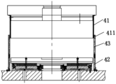
- Fig. 4 shows the partial structural representation of the vulcanization chamber embodiment of the vulcanizer of the present application
- Fig. 5 shows a schematic diagram of an embodiment of the heating plate of the vulcanizer of the present application.
- a vulcanizing machine includes: a cylinder assembly 10, a bladder, a first mold body and a second mold body, the first mold body and the second mold body are relatively movably arranged, so as to The tire is vulcanized when the mold body and the second mold body are closed; the bladder is arranged in the second mold body to support the inner side of the tire after the bladder is inflated; After inflation, push the second mold body to move toward the first mold body so that the second mold body and the first mold body are closed.
- the application provides an energy-saving and environment-friendly vulcanizing machine. After the first mold body and the second mold body of the vulcanizer are closed, the tire inside the mold body is vulcanized. At this time, the bladder is located on the inner side of the tire. Fill the air with a predetermined pressure to support the inner wall of the tire. However, when the pressure in the bladder is high, it will also push up the first mold body above, so that the first mold body and the second mold body are not tightly closed or separated.
- the cylinder assembly 10 is designed to drive and connect with the second mold body below, so that after the capsule is inflated, it will apply a force to the second mold body to move towards the first mold body, so as to counteract the impact caused by the capsule being propped up.
- the force exerted by the first mold body solves the problem of poor sealing between the first mold body and the second mold body.
- the driving cylinder is arranged at the bottom of the vulcanization chamber without oil supply. The structure is simple, easy to maintain, and energy-saving and environmentally friendly.
- the cylinder assembly 10 adopts an annular air cylinder, which is arranged on the bottom of the second mold body to drive the second mold body to move up and down.
- annular cylinder In order to apply an upward force to the second mold body evenly, so that the second mold body moves synchronously as a whole, and at the same time, for the convenience of installation, an annular cylinder is used to drive the second mold body to move.
- Vulcanizer also comprises frame 60, manipulator assembly 21 and drive motor 22, and manipulator assembly 21 is movably arranged on frame 60, to loading and unloading tire in the vulcanizer;
- Drive motor 22 is arranged on frame 60, and drive motor 22 It is drivingly connected with the manipulator assembly 21 to drive the manipulator assembly 21 to move up and down.
- the manipulator assembly 21 includes a tire loading manipulator and a tire unloading manipulator, and the vulcanizer also includes a transmission screw assembly 23, which is connected to a drive motor 22, and the tire loading manipulator and the tire unloading manipulator are respectively movably arranged on the transmission screw assembly 23. Component 23 on.
- the manipulator assembly 21 in the present embodiment is driven by the driving motor 22, and there are two driving motors 22, which are respectively arranged on both sides of the top of the frame 60, and the driving screw assembly 23 includes two driving screw
- the manipulator assembly 21 includes a tire loading manipulator for putting tires in the vulcanization chamber and a tire unloading manipulator for taking out the tires in the vulcanization chamber.
- the transmission screw rotates, thereby driving the tire loading manipulator and the tire unloading manipulator to move up and down.
- the tire loading manipulator and the tire unloading manipulator can also rotate horizontally relative to the transmission screw respectively to complete the function of loading and unloading tires.
- Vulcanizing machine also comprises the 3rd shield 43, the first shield 41 and the second shield 42, and the first shield 41 is connected with the first mold, and the second shield 42 is connected with the second mold;
- the 3rd shield 43 can be Telescopically connected with the first shield 41 and/or the second shield 42, so that when the first mold and the second mold are connected, the first shield 41 is connected with the second shield 42 through the third shield 43, to form a vulcanization space.
- the present application provides a vulcanization chamber shield for sealing the mould, the vulcanization chamber shield is divided into three parts along the vertical direction, successively the first shield 41, the third shield 43 and the second shield 42 , when the third shield 43 is connected with the first shield 41, the third shield 43 can slide and expand relative to the first shield 41, and when the third shield 43 is connected with the second shield 42, the third shield 43 Can slide relative to the second shield 42, when the first mold and the second mold are closed, the first shield 41 is sealed with the second shield 42 through the third shield 43, so that the first mold and the second mold Sealed in the shield, the vulcanization chamber shield of the present application can be adjusted and stretched in the height direction according to the specifications of different molds, and has better applicability.
- a vacuum valve is also arranged on the first shield 41 or the second shield 42, and the vacuum valve is opened to seal the vulcanization chamber shield. Vacuum the space inside.
- a sealing ring is provided between the first shield 41, the third shield 43 and the second shield 42, wherein the third shield 43 A sealing groove is provided on the inner wall for installing the first sealing ring 411. Since the first shield 41 and the third shield 43 need to move relative to each other, the first sealing ring 411 adopts a Y-shaped sealing ring, the opening faces, and the second The sealing ring is arranged on the bottom of the third shield 43, and can also be arranged on the top of the second shield 42. In addition, the second sealing ring can also be arranged on the bottom of the third shield 43 and the top of the second shield 42. .
- the first shield 41 , the second shield 42 and the third shield 43 are all provided with thermal insulation layers.
- the first shield 41, the second shield 42 and the third shield 43 all adopt a double-layer structure design, and are respectively provided with an inner wall and an outer wall. Adding insulation material can effectively insulate heat.
- the vulcanizer also includes: a first shield 41 and a second shield 42, the first shield 41 and the second shield 42 are relatively movably arranged, so that when the first shield 41 is connected with the second shield 42, A sealed cavity for vulcanizing the tire carcass is formed; wherein, the first shield 41 has an inner wall and an outer wall, and a vacuum cavity is provided between the inner wall and the outer wall to reduce heat conduction between the inner wall and the outer wall.
- a vacuum interface is provided on the outer wall
- the vulcanizer also includes: a vacuum valve, which is installed on the first shield 41 or the second shield 42 and communicates with the vacuum chamber to evacuate the vacuum chamber.
- a filling component is provided inside the vacuum chamber to reduce heat conduction between the inner wall and the outer wall.
- the vulcanization chamber of the vulcanizer of the present application adopts vacuum technology to isolate the heat inside and outside the vulcanization chamber.
- the vulcanization chamber shield adopts a double-layer design.
- the problem of setting the interface in the hole on the shield makes the sealing of the entire vulcanization chamber shield better.
- a vacuum valve is set on the outer wall of the shield and connected with a vacuum pump to real-time control the shield when the vulcanization chamber is working.
- the vacuum chamber of the interlayer is vacuumed, and the heat insulation effect of the vacuum chamber is better.
- a filling component is installed in the vacuum chamber, and the filling component is made of glass fiber or fireproof cotton, which is a heat insulating material, for further heat insulation.
- the vulcanizer also includes a second heating assembly, which is arranged in the vulcanization chamber to heat the vulcanization cavity of the vulcanization chamber, wherein the second heating assembly includes a heating plate device and an electric heating tube device, and the heating plate device is arranged in In the vulcanization chamber: the electric heating tube device is arranged on the heating plate device to provide heat to the vulcanization chamber through the heating plate device.
- the vulcanizing machine is provided with a capsule, and the vulcanizing machine also includes: a gas delivery channel and a first heating assembly 51, the gas delivery channel communicates with the capsule to expand the capsule by delivering gas to the capsule; the first heating assembly 51 is arranged on the gas delivery channel channel to heat the gas delivered to the capsule.
- the vulcanizing machine of the present application uses electric heating to provide heat to the vulcanization chamber to vulcanize the tires.
- the heating plate device is provided with upper and lower heating plates 20, and the two heating plates 20 are respectively equipped with electric heaters. tube to provide heat to the heating plate 20, and then heat the tire in the mold through the heating plate 20.
- a first heating assembly 51 is also provided.
- the first heating assembly 51 adopts electric The heating wire is wound around the air inlet of the capsule, so that when the capsule is inflated, the capsule will also generate heat by heating the gas to heat the inside of the tire to ensure that the inside and outside of the tire are evenly heated.
- the vulcanization chamber also includes a central mechanism.
- the central mechanism is provided with an upper ring oil cylinder and an upper support rod 52.
- the upper support rod 52 is connected to the capsule. The support moves; wherein, the air delivery channel is set in the upper support rod 52 .
- the bottom of the vulcanization chamber of the present application is also provided with a central mechanism, which can drive the capsule to move.
- the upper support rod 52 that drives the capsule to move is designed as a hollow rod, so that the upper support rod 52 is driven. While the capsule is moving, gas can also be delivered into the capsule through the internal channel.
- An air outlet 521 is provided on the top of the upper support rod 52 , and the first heating assembly 51 is disposed at the air outlet 521 . There are a plurality of air outlets 521 , and the plurality of air outlets 521 are arranged at intervals around the top of the upper support rod 52 .
- the first heating assembly 51 is heated by an electric heating wire wound on the upper support rod 52 .
- This application sets a circle of air outlet 521 on the top of the upper support rod 52.
- the electric heating wire is wound around the air outlet 521, so that the nitrogen gas passes through the electric heating wire when passing through the air outlet 521.
- the heating temperature of the heating wire increases, and then the capsule is heated.
- the vulcanization chamber also includes a protective sheath 53, which is arranged on the outside of the electric heating wire.
- the protective cover 53 is made of high-temperature-resistant material, and the protective cover 53 has a heat insulation function to prevent the electric heating wire from directly contacting the capsule. Furthermore, the protective cover 53 is provided with a plurality of holes for air outlet.
- the application provides an energy-saving and environment-friendly vulcanizing machine. After the first mold body and the second mold body of the vulcanizer are closed, the tire inside the mold body is vulcanized. At this time, the bladder is located on the inner side of the tire. Fill the air with a predetermined pressure to support the inner wall of the tire. However, when the pressure in the bladder is high, it will also push up the first mold body above, so that the first mold body and the second mold body are not tightly closed or separated.
- the cylinder assembly 10 is designed to drive and connect with the second mold body below, so that after the capsule is inflated, it will apply a force to the second mold body to move towards the first mold body, so as to counteract the impact caused by the capsule being propped up.
- the force exerted by the first mold body solves the problem of poor sealing between the first mold body and the second mold body.
- the driving cylinder is arranged at the bottom of the vulcanization chamber without oil supply. The structure is simple, easy to maintain, and energy-saving and environmentally friendly.
- the vulcanizing machine of this application upgrades the energy medium on the basis of the existing steam vulcanization: from steam heat energy to electric heat energy, on the basis of satisfying the tire vulcanization pressure and temperature, an electric heating device (inner/outer) is added, and advanced
- the temperature control module realizes the deviation of the internal and external temperature within the set temperature range of ⁇ 1.5 °C.
- this application also simplifies the hydraulic system, cancels the mold clamping force pressurization cylinder of the high pressure part, uses the air pressurization method, and cooperates with the internal pressure nitrogen in the original thermal system at the same time, and can realize mold clamping without adding a new pressure source Pressurize;
- the lifting cylinder of the manipulator is eliminated, and the structure of servo motor + ball screw is used to drive. While satisfying the position accuracy, the servo adjustment of the driving power can be realized according to the change of the load, saving energy and running more smoothly.
- a new vacuum vulcanization chamber structure is adopted, equipped with a vacuum pump and a vacuum vulcanization chamber that meets the sealing requirements. After the mold is closed, the vulcanization chamber is evacuated to exhaust all excess air to ensure the tight fit between the raw tire and the mold. Instead of "cavitation", while improving the quality of tire products, it reduces the shaving process for tire companies and further reduces production and operation costs.
- the second heating assembly of this application is divided into an upper heating plate and a lower heating plate. Spiral grooves are respectively arranged on the upper and lower heating plates for installing electric heating tubes.
- the bendable electric heating tubes are used for easy assembly, and voltage control is used to realize power and temperature. Controllable, through the advanced temperature control system, to ensure the temperature control of different areas, to ensure that the temperature difference of the hot plate is ⁇ 1.5 °C.
- the vulcanizing machine of the present application heats the nitrogen gas from the original internal pressure source to the process temperature by installing an electric heating device deep inside the bladder in the central mechanism, so as to meet the internal temperature requirements of tire vulcanization.
- sealing devices By setting sealing devices on the upper main board (upper hot plate mounting plate) and lower backing plate (lower hot plate mounting plate) in the vulcanizing chamber, setting a sealing shield around the vulcanizing chamber, installing sealing devices according to the upper, middle and west three-level positions, through the vacuum pump Function, to realize the vacuuming operation in the vulcanization chamber.
- the excess air in the vulcanizing chamber is evacuated to prevent the cavitation phenomenon of tire vulcanization and ensure the shape of the vulcanized tire.
- the vent holes on the periphery of the mold can be canceled, so that the vulcanized tire has no lanugo, which reduces the current manual or machine shaving process.
- the servo motor can reduce the transmission power and save energy according to the load feedback.
Landscapes
- Physics & Mathematics (AREA)
- Health & Medical Sciences (AREA)
- Oral & Maxillofacial Surgery (AREA)
- Thermal Sciences (AREA)
- Engineering & Computer Science (AREA)
- Mechanical Engineering (AREA)
- Heating, Cooling, Or Curing Plastics Or The Like In General (AREA)
- Moulds For Moulding Plastics Or The Like (AREA)
Abstract
本申请提供了一种硫化机,包括:第一模体和第二模体,第一模体和第二模体相对可移动地设置,以在第一模体和第二模体靠近闭合时对轮胎进行硫化;胶囊,胶囊设置在第二模体内,以在向胶囊充气后使胶囊支撑轮胎的内侧;气缸组件,气缸组件与第二模体驱动连接,以在胶囊充气后推动第二模体朝向第一模体移动使第二模体与第一模体闭合。本申请的硫化机解决了现有技术中的硫化机不节能环保的问题。
Description
本申请要求于2021年9月30日提交至中国国家知识产权局、申请号为202111166788.X、发明名称为“硫化机”的专利申请的优先权。
本申请涉及硫化机领域,具体而言,涉及一种硫化机。
轮胎硫化机是生产轮胎过程中最后一道硫化工序的专用设备,早期主要采用机械式双模硫化机,此种机型笨重且精度不高,更不能满足智能控制的要求,于是,液压硫化机出现,直至现在各轮胎企业皆采用液压式双模硫化机来实现轮胎制品的生产效率、质量的提升。
液压式双模硫化机主要是解决了各动作的平稳控制,开合模、机械手升降、活络模驱动、中心机构上/下环升降等动作采用液压油缸驱动,运动过程的速度、位置实现了高精度控制,现行液压硫化机主要通过液压实现整机各动作的位置及速度控制,同时提供轮胎硫化所需的合模力。通过蒸汽与氮气双介质提供硫化所需内压及温度。通过在模具上打放气孔实现合模后模具腔体内的气体排出,保证硫化后轮胎型体。
然而,蒸汽和液压在长时间的使用后会对管路或硫化机造成一定的腐蚀,蒸汽、液压中存在的跑冒滴漏问题,造成了对于企业生产环境的恶劣影响。
随着轮胎制品市场竞争环境的加剧,推动了企业对于节能降耗,降低生产制造成本的强烈需求,而硫化工序的能耗约占整个轮胎生产成本的60%,所以轮胎制造企业对于硫化工序的节能降耗创新升级需求强烈。
此外,轮胎硫化生产工序,需要大量的热量,属于高压、高温工况,此工况下的液压系统极易出现管路接头老化,液压油在高温下(>60℃)运行导致的密封损害等问题,造成液压油泄露,加大了生产维护成本的同时,还有污染地下水质,破坏生态环境的问题。
发明内容
本申请的主要目的在于提供一种硫化机,以解决现有技术中的硫化机不节能环保的问题。
为了实现上述目的,根据本申请的一个方面,提供了一种硫化机,包括:第一模体和第二模体,第一模体和第二模体相对可移动地设置,以在第一模体和第二模体靠近闭合时对轮胎进行硫化;胶囊,胶囊设置在第二模体内,以在向胶囊充气后使胶囊支撑轮胎的内侧;气缸组件,气缸组件与第二模体驱动连接,以在胶囊充气后推动第二模体朝向第一模体移动使第二模体与第一模体闭合。
在一个实施例中,气缸组件采用环形气缸,环形气缸设置在第二模体的底部,以驱动第二模体升降移动。
在一个实施例中,硫化机还包括:机架;机械手组件,机械手组件可移动地设置在机架上,以向硫化机内装卸轮胎;驱动电机,驱动电机设置在机架上,驱动电机与机械手组件驱动连接,以驱动机械手组件升降移动。
在一个实施例中,机械手组件包括装胎机械手和卸胎机械手,硫化机还包括:传动丝杠组件,传动丝杠组件与驱动电机连接,所装胎机械手和卸胎机械手分别可移动地设置在传动丝杠组件上。
在一个实施例中,硫化机还包括:第一护罩和第二护罩,第一护罩与第一模具连接,第二护罩与第二模具连接;第三护罩,第三护罩可伸缩地与第一护罩和/或第二护罩连接,以在第一模具和第二模具连接时,使第一护罩通过第三护罩与第二护罩连接,以形成硫化空间。
在一个实施例中,硫化机还包括:第一护罩和第二护罩,第一护罩和第二护罩相对可移动地设置,以在第一护罩与第二护罩连接时,形成用于硫化轮胎胎体的密封腔;其中,第一护罩具有内壁和外壁,内壁和外壁之间设有真空腔,以减小内壁和外壁之间的热传导。
在一个实施例中,外壁上设有真空接口,硫化机还包括:真空阀,真空阀安装在第一护罩或第二护罩上,并与真空腔连通,以对真空腔抽真空。
在一个实施例中,真空腔内设有填充组件,以减小内壁和外壁之间的热传导。
在一个实施例中,硫化机还包括第二加热组件,第二加热组件设置在硫化室内,以给硫化室的的硫化腔进行加热,其中,第二加热组件包括:加热板装置,加热板装置设置在硫化室内;电加热管装置,电加热管装置设置在加热板装置上,以通过加热板装置给硫化室提供热量。
在一个实施例中,硫化机内设有胶囊,述硫化机还包括:输气通道,输气通道与胶囊连通,以通过向胶囊内输送气体使胶囊膨胀;第一加热组件,第一加热组件设置在输气通道上,以对向胶囊输送的气体进行加热。
本申请的硫化机的第一模体和第二模体在闭合后,对模体内部的轮胎进行硫化,此时,胶囊位于轮胎的内侧,通过向胶囊内充入预定压力的气体来支撑轮胎内壁,然而当胶囊内的压力较大时,也会将上方的第一模体顶起来,从而使第一模体与第二模体闭合不严或分离,本申请设计了气缸组件与下方的第二模体驱动连接,以在胶囊充气后,给第二模体施加一个朝向第一模体移动的力,以此来抵消胶囊被撑起后给第一模体施加的力,解决了第一模体和第二模体密封不严的问题,同时驱动气缸设置在硫化室底部,无需供油,结构简单,维护方便且节能环保。
构成本申请的一部分的说明书附图用来提供对本申请的进一步理解,本申请的示意性实施例及其说明用于解释本申请,并不构成对本申请的不当限定。在附图中:
图1示出了根据本申请的硫化机的实施例的第一视角示意图;
图2示出了本申请的硫化机的实施例的第二视角示意图;
图3示出了本申请的硫化机的硫化室护罩实施例的示意图;
图4示出了本申请的硫化机的硫化室实施例的部分结构示意图;
图5示出了本申请的硫化机的加热板实施例的示意图。
其中,上述附图包括以下附图标记:
10、气缸组件;20、加热板;21、机械手组件;22、驱动电机;23、传动丝杠组件;41、第一护罩;411、第一密封圈;42、第二护罩;43、第三护罩;51、第一加热组件;52、上支撑杆;521、出气口;53、保护套;60、机架。
需要说明的是,在不冲突的情况下,本申请中的实施例及实施例中的特征可以相互组合。下面将参考附图并结合实施例来详细说明本申请。
请参考图1至图5,一种硫化机,包括:气缸组件10、胶囊、第一模体和第二模体,第一模体和第二模体相对可移动地设置,以在第一模体和第二模体靠近闭合时对轮胎进行硫化;胶囊设置在第二模体内,以在向胶囊充气后使胶囊支撑轮胎的内侧;气缸组件10与第二模体驱动连接,以在胶囊充气后推动第二模体朝向第一模体移动使第二模体与第一模体闭合。
本申请提供了一种节能环保的硫化机,该硫化机的第一模体和第二模体在闭合后,对模体内部的轮胎进行硫化,此时,胶囊位于轮胎的内侧,通过向胶囊内充入预定压力的气体来支撑轮胎内壁,然而当胶囊内的压力较大时,也会将上方的第一模体顶起来,从而使第一模体与第二模体闭合不严或分离,本申请设计了气缸组件10与下方的第二模体驱动连接,以在胶囊充气后,给第二模体施加一个朝向第一模体移动的力,以此来抵消胶囊被撑起后给第一模体施加的力,解决了第一模体和第二模体密封不严的问题,同时驱动气缸设置在硫化室底部,无需供油,结构简单,维护方便且节能环保。
气缸组件10采用环形气缸,环形气缸设置在第二模体的底部,以驱动第二模体升降移动。
为了均匀的给第二模体施加向上的力,使第二模体同步整体移动,同时为了便于安装,采用环形气缸驱动第二模体进行移动。
硫化机还包括机架60、机械手组件21和驱动电机22,机械手组件21可移动地设置在机架60上,以向硫化机内装卸轮胎;驱动电机22设置在机架60上,驱动电机22与机械手组件21驱动连接,以驱动机械手组件21升降移动。机械手组件21包括装胎机械手和卸胎机械 手,硫化机还包括传动丝杠组件23,传动丝杠组件23与驱动电机22连接,所装胎机械手和卸胎机械手分别可移动地设置在传动丝杠组件23上。
如图1所示,本实施例中的机械手组件21通过驱动电机22进行驱动,驱动电机22为两个,分别设置在机架60上部的两侧,传动丝杠组件23包括两个传动丝杠,机械手组件21包括一个向硫化室内放轮胎的装胎机械手和一个将硫化室内轮胎取出的卸胎机械手,装胎机械手和卸胎机械手分别设置在两个传动丝杠上,一个驱动电机22驱动一个传动丝杠转动,从而带动装胎机械手和卸胎机械手升降移动,此外,装胎机械手和卸胎机械手还分别能够相对传动丝杠进行水平转动,以完成装卸轮胎的功能。
硫化机还包括第三护罩43、第一护罩41和第二护罩42,第一护罩41与第一模具连接,第二护罩42与第二模具连接;第三护罩43可伸缩地与第一护罩41和/或第二护罩42连接,以在第一模具和第二模具连接时,使第一护罩41通过第三护罩43与第二护罩42连接,以形成硫化空间。
本申请提供了一种用于密封模具的硫化室护罩,该硫化室护罩沿竖直方向上分为三部分,依次为第一护罩41、第三护罩43和第二护罩42,第三护罩43与第一护罩41连接时,第三护罩43能够相对第一护罩41相对滑动伸缩,第三护罩43与第二护罩42连接时,第三护罩43能够相对第二护罩42滑动移动,当第一模具和第二模具闭合时,第一护罩41通过第三护罩43与第二护罩42密封连接,以将第一模具和第二模具密封在护罩内,本申请的硫化室护罩能够根据不同模具的规格在高度方向上可调节伸缩,适用性更好。
当第一护罩41、第三护罩43和第二护罩42密封连接后,在第一护罩41或第二护罩42上还设有真空阀,打开真空阀以对硫化室护罩内侧的空间抽真空。
如图2所示,为了保证硫化室护罩的密封性,在第一护罩41、第三护罩43和第二护罩42之间均设有密封圈,其中,在第三护罩43内壁上设有一圈密封槽以用于安装第一密封圈411,由于第一护罩41和第三护罩43需要相对移动,故第一密封圈411采用Y型密封圈,开口朝向,第二密封圈设置在第三护罩43的底部,也可以设置在第二护罩42的顶部,此外,还可以在第三护罩43的底部和第二护罩42的顶部均设置第二密封圈。
第一护罩41、第二护罩42和第三护罩43内均设有保温层。
第一护罩41、第二护罩42和第三护罩43均采用双层结构设计,分别设有内壁和外壁,在内壁和外壁之间的空间抽真空,并填充隔热材料,真空层加隔热材料能够有效进行隔热。
硫化机还包括:第一护罩41和第二护罩42,第一护罩41和第二护罩42相对可移动地设置,以在第一护罩41与第二护罩42连接时,形成用于硫化轮胎胎体的密封腔;其中,第一护罩41具有内壁和外壁,内壁和外壁之间设有真空腔,以减小内壁和外壁之间的热传导。外壁上设有真空接口,硫化机还包括:真空阀,真空阀安装在第一护罩41或第二护罩42上,并与真空腔连通,以对真空腔抽真空。真空腔内设有填充组件,以减小内壁和外壁之间的热传导。
本申请的硫化机的硫化室采用真空技术来隔绝硫化室内外的热量,具体的,硫化室护罩采用双层设计,通过采用电加热的方式后,有效解决了整体和热油需要在硫化室护罩上开孔设置接口的问题,使的整个硫化室护罩密封性更好,此外,在护罩的外壁上设置真空阀,与真空泵连接,以在硫化室进行工作时,实时对防护罩夹层的真空腔进行抽真空作业,真空腔的隔热效果更好,同时在真空腔内设置填充组件,填充组件采用隔热材料的玻璃纤维或防火棉等,进一步隔热。
硫化机还包括第二加热组件,第二加热组件设置在硫化室内,以给硫化室的的硫化腔进行加热,其中,第二加热组件包括加热板装置和电加热管装置,加热板装置设置在硫化室内;电加热管装置设置在加热板装置上,以通过加热板装置给硫化室提供热量。
硫化机内设有胶囊,述硫化机还包括:输气通道和第一加热组件51,输气通道与胶囊连通,以通过向胶囊内输送气体使胶囊膨胀;第一加热组件51设置在输气通道上,以对向胶囊输送的气体进行加热。
本申请的硫化机采用电加热的方式来给硫化室提供热量,以对轮胎进行硫化,具体的,加热板装置设有上、下两个加热板20,两个加热板20上分别设置电加热管,以给加热板20提供热量,进而通过加热板20给模具内的轮胎加热,此外,为了保证轮胎内侧的温度与外侧一致,还设置了第一加热组件51,第一加热组件51采用电加热丝,缠绕在胶囊的进气口位置处,以在向胶囊充气时,通过对气体进行加热,使胶囊也产生热量,对轮胎的内侧进行加热,保证轮胎内外受热均匀。
硫化室还包括中心机构,中心机构上设有上环油缸和上支撑杆52,上支撑杆52与胶囊连接,上环油缸与上支撑杆52驱动连接,以通过上支撑杆52驱动胶囊的上支座移动;其中,输气通道设置在上支撑杆52内。
本申请的硫化室底部还设有中心机构,中心机构能够驱动胶囊移动,为了方便向胶囊内输送气体,将驱动胶囊移动的上支撑杆52设计成中空的杆,使得该上支撑杆52在驱动胶囊移动的同时还能够通过内部的通道向胶囊内输送气体。
上支撑杆52顶部设有出气口521,第一加热组件51设置在出气口521处。出气口521为多个,多个出气口521环绕在上支撑杆52的顶部间隔地设置。第一加热组件51采用电加热丝加热,电加热丝缠绕在上支撑杆52上。
本申请在上支撑杆52的顶端设置了一圈出气口521,为了便于固定电加热丝,采用将电加热丝缠绕在出气口521位置的方式,从而使的氮气在经过出气口521时通过电加热丝的加热温度升高,进而对胶囊进行加热。
硫化室还包括保护套53,保护套53罩设在电加热丝的外侧。该保护套53采用耐高温的材料,且保护套53具有隔热作用,防止电加热丝与胶囊直接接触,进一步,保护套53上设有多个孔以用于出气。
从以上的描述中,可以看出,本申请上述的实施例实现了如下技术效果:
本申请提供了一种节能环保的硫化机,该硫化机的第一模体和第二模体在闭合后,对模体内部的轮胎进行硫化,此时,胶囊位于轮胎的内侧,通过向胶囊内充入预定压力的气体来支撑轮胎内壁,然而当胶囊内的压力较大时,也会将上方的第一模体顶起来,从而使第一模体与第二模体闭合不严或分离,本申请设计了气缸组件10与下方的第二模体驱动连接,以在胶囊充气后,给第二模体施加一个朝向第一模体移动的力,以此来抵消胶囊被撑起后给第一模体施加的力,解决了第一模体和第二模体密封不严的问题,同时驱动气缸设置在硫化室底部,无需供油,结构简单,维护方便且节能环保。
本申请的硫化机在现有蒸汽硫化的基础上,升级能源介质:由蒸汽热能升级为电热能,在满足轮胎硫化压力、温度的基础上,增设电加热装置(内/外),并通过先进的温控模块,实现内外温在设定温度范围内偏差±1.5℃。通过能源介质的升级优化,整机结构进一步简化:热板无需铣槽焊接,内外温管路精简,生产使用成本降低40%;通过能源介质的升级优化,传统蒸汽能取消,终端轮胎用户的投资建厂成本大大降低,工厂管道、阀门大大减少,维护人工、备件大大减少,日常投入成本大大降低;通过能源介质优化,原蒸汽通道的跑冒滴漏现象消失,工厂车间的工作环境大大优化,操作人员工作场所进一步美化。
进一步本申请还简化液压系统,取消高压部分的合模力加压油缸,使用气加压方式,同时与原热工系统中的内压氮气相配合,无需增加新的压力源即可实现合模力加压;
在一个实施例中,取消机械手升降油缸,采用伺服电机+滚珠丝杠结构驱动,满足位置精度的同时,可根据负载的变化实现驱动功率的伺服调节,节约能源,运行更平稳。
此外,采用全新的真空硫化室结构,配备真空泵及满足密封要求的真空硫化室,在合模后,对硫化室内实施抽真空,将多余空气全部排空,保证生胎与模具的紧密贴合,而不会出现“气蚀”,在提升轮胎制品质量的同时,为轮胎企业减掉了剃毛工序,进一步降低了生产经营成本。
本申请的第二加热组件分为上热板和下热板,分别在上下热板设置螺旋槽,用于安装电热管,采用可折弯式电热管,便于装配,采用电压控制实现功率、温度的可控,通过先进的温控系统,保证不同区域温度的控制,保证热板温差±1.5℃。
本申请的硫化机通过在中心机构设置深入胶囊内部的电加热装置,对原内压源氮气加热到工艺温度,满足轮胎硫化的内温要求。
通过在硫化室上主板(上热板安装板)、下垫板(下热板安装板)设置密封装置,在硫化室外围设置密封护罩,按上中西三层级位置加装密封装置,通过真空泵作用,实现硫化室内抽真空作业。
通过对硫化室抽真空,在硫化机合模后,将硫化室内多余空气抽空,防止轮胎硫化的气蚀现象,保证硫化后轮胎外形。同时,可取消模具外围的排气孔,使硫化后的轮胎没有胎毛,减少了现在人工或机器的剃毛工序。
安装卸胎机械手的升降运动位置,升级为伺服电机驱动滚珠丝杠的传动结构,取消原装卸胎油缸,减少液压泄漏点的同时,实现机械手动作有胎/无胎的不同功率控制,即无胎状态下,伺服电机根据负载反馈,可降低传动功率,节约能源。
需要注意的是,这里所使用的术语仅是为了描述具体实施方式,而非意图限制根据本申请的示例性实施方式。如在这里所使用的,除非上下文另外明确指出,否则单数形式也意图包括复数形式,此外,还应当理解的是,当在本说明书中使用术语“包含”和/或“包括”时,其指明存在特征、步骤、操作、器件、组件和/或它们的组合。
以上所述仅为本申请的优选实施例而已,并不用于限制本申请,对于本领域的技术人员来说,本申请可以有各种更改和变化。凡在本申请的精神和原则之内,所作的任何修改、等同替换、改进等,均应包含在本申请的保护范围之内。
Claims (10)
- 一种硫化机,其特征在于,包括:第一模体和第二模体,所述第一模体和所述第二模体相对可移动地设置,以在所述第一模体和所述第二模体靠近闭合时对轮胎进行硫化;胶囊,所述胶囊设置在所述第二模体内,以在向所述胶囊充气后使所述胶囊支撑所述轮胎的内侧;气缸组件(10),所述气缸组件(10)与所述第二模体驱动连接,以在所述胶囊充气后推动所述第二模体朝向所述第一模体移动使所述第二模体与所述第一模体闭合。
- 根据权利要求1所述的硫化机,其特征在于,所述气缸组件采用环形气缸,所述环形气缸设置在所述第二模体的底部,以驱动所述第二模体升降移动。
- 根据权利要求1所述的硫化机,其特征在于,所述硫化机还包括:机架;机械手组件(21),所述机械手组件(21)可移动地设置在所述机架上,以向所述硫化机内装卸轮胎;驱动电机(22),所述驱动电机(22)设置在所述机架上,所述驱动电机(22)与所述机械手组件(21)驱动连接,以驱动所述机械手组件(21)升降移动。
- 根据权利要求3所述的硫化机,其特征在于,所述机械手组件(21)包括装胎机械手和卸胎机械手,所述硫化机还包括:传动丝杠组件(23),所述传动丝杠组件(23)与所述驱动电机(22)连接,所装胎机械手和所述卸胎机械手分别可移动地设置在所述传动丝杠组件(23)上。
- 根据权利要求1所述的硫化机,其特征在于,所述硫化机还包括:第一护罩(41)和第二护罩(42),所述第一护罩(41)与第一模具连接,所述第二护罩(42)与第二模具连接;第三护罩(43),所述第三护罩(43)可伸缩地与所述第一护罩(41)和/或所述第二护罩(42)连接,以在所述第一模具和所述第二模具连接时,使所述第一护罩(41)通过所述第三护罩(43)与所述第二护罩(42)连接,以形成硫化空间。
- 根据权利要求1所述的硫化机,其特征在于,所述硫化机还包括:第一护罩(41)和第二护罩(42),所述第一护罩(41)和所述第二护罩(42)相对可移动地设置,以在所述第一护罩(41)与所述第二护罩(42)连接时,形成用于硫化轮胎胎体的密封腔;其中,所述第一护罩(41)具有内壁和外壁,所述内壁和所述外壁之间设有真空腔, 以减小所述内壁和所述外壁之间的热传导。
- 根据权利要求6所述的硫化机,其特征在于,所述外壁上设有真空接口,所述硫化机还包括:真空阀,所述真空阀安装在所述第一护罩(41)或所述第二护罩(42)上,并与所述真空腔连通,以对所述真空腔抽真空。
- 根据权利要求7所述的硫化机,其特征在于,所述真空腔内设有填充组件,以减小所述内壁和所述外壁之间的热传导。
- 根据权利要求1所述的硫化机,其特征在于,所述硫化机还包括第二加热组件,所述第二加热组件设置在硫化室内,以给所述硫化室的的硫化腔进行加热,其中,所述第二加热组件包括:加热板装置,所述加热板装置设置在所述硫化室内;电加热管装置,所述电加热管装置设置在所述加热板装置上,以通过所述加热板装置给所述硫化室提供热量。
- 根据权利要求1所述的硫化机,其特征在于,所述硫化机内设有胶囊,述硫化机还包括:输气通道,所述输气通道与所述胶囊连通,以通过向所述胶囊内输送气体使所述胶囊膨胀;第一加热组件(51),所述第一加热组件(51)设置在所述输气通道上,以对向所述胶囊输送的气体进行加热。
Applications Claiming Priority (2)
| Application Number | Priority Date | Filing Date | Title |
|---|---|---|---|
| CN202111166788.X | 2021-09-30 | ||
| CN202111166788.XA CN113858503A (zh) | 2021-09-30 | 2021-09-30 | 硫化机 |
Publications (1)
| Publication Number | Publication Date |
|---|---|
| WO2023051826A1 true WO2023051826A1 (zh) | 2023-04-06 |
Family
ID=79001650
Family Applications (1)
| Application Number | Title | Priority Date | Filing Date |
|---|---|---|---|
| PCT/CN2022/123587 WO2023051826A1 (zh) | 2021-09-30 | 2022-09-30 | 硫化机 |
Country Status (2)
| Country | Link |
|---|---|
| CN (1) | CN113858503A (zh) |
| WO (1) | WO2023051826A1 (zh) |
Families Citing this family (2)
| Publication number | Priority date | Publication date | Assignee | Title |
|---|---|---|---|---|
| CN113715222A (zh) * | 2021-09-30 | 2021-11-30 | 软控股份有限公司 | 硫化室及硫化机 |
| CN113858503A (zh) * | 2021-09-30 | 2021-12-31 | 软控股份有限公司 | 硫化机 |
Citations (8)
| Publication number | Priority date | Publication date | Assignee | Title |
|---|---|---|---|---|
| US4927344A (en) * | 1988-02-29 | 1990-05-22 | Kabushiki Kaisha Kobe Seiko Sho | Steam dome type vertical tire press |
| JPH04147808A (ja) * | 1990-10-11 | 1992-05-21 | Sumitomo Rubber Ind Ltd | タイヤ加硫用金型 |
| CN2785838Y (zh) * | 2004-12-23 | 2006-06-07 | 伏启岩 | 机模合一轮胎硫化机 |
| CN204869385U (zh) * | 2015-03-07 | 2015-12-16 | 山东鸿建机械科技有限公司 | 硫化机自适应保温罩装置 |
| CN207711157U (zh) * | 2018-01-11 | 2018-08-10 | 巨轮智能装备股份有限公司 | 一种四柱锁轴式液压轮胎硫化机 |
| CN113211841A (zh) * | 2021-06-17 | 2021-08-06 | 昆明云仁轮胎制造有限公司 | 一种自行车外胎一体化整型硫化装置 |
| CN113858503A (zh) * | 2021-09-30 | 2021-12-31 | 软控股份有限公司 | 硫化机 |
| CN114603893A (zh) * | 2020-12-07 | 2022-06-10 | 软控股份有限公司 | 硫化机及轮胎硫化方法 |
-
2021
- 2021-09-30 CN CN202111166788.XA patent/CN113858503A/zh active Pending
-
2022
- 2022-09-30 WO PCT/CN2022/123587 patent/WO2023051826A1/zh unknown
Patent Citations (8)
| Publication number | Priority date | Publication date | Assignee | Title |
|---|---|---|---|---|
| US4927344A (en) * | 1988-02-29 | 1990-05-22 | Kabushiki Kaisha Kobe Seiko Sho | Steam dome type vertical tire press |
| JPH04147808A (ja) * | 1990-10-11 | 1992-05-21 | Sumitomo Rubber Ind Ltd | タイヤ加硫用金型 |
| CN2785838Y (zh) * | 2004-12-23 | 2006-06-07 | 伏启岩 | 机模合一轮胎硫化机 |
| CN204869385U (zh) * | 2015-03-07 | 2015-12-16 | 山东鸿建机械科技有限公司 | 硫化机自适应保温罩装置 |
| CN207711157U (zh) * | 2018-01-11 | 2018-08-10 | 巨轮智能装备股份有限公司 | 一种四柱锁轴式液压轮胎硫化机 |
| CN114603893A (zh) * | 2020-12-07 | 2022-06-10 | 软控股份有限公司 | 硫化机及轮胎硫化方法 |
| CN113211841A (zh) * | 2021-06-17 | 2021-08-06 | 昆明云仁轮胎制造有限公司 | 一种自行车外胎一体化整型硫化装置 |
| CN113858503A (zh) * | 2021-09-30 | 2021-12-31 | 软控股份有限公司 | 硫化机 |
Also Published As
| Publication number | Publication date |
|---|---|
| CN113858503A (zh) | 2021-12-31 |
Similar Documents
| Publication | Publication Date | Title |
|---|---|---|
| WO2023051826A1 (zh) | 硫化机 | |
| WO2010045845A1 (zh) | 连续式抽真空设备的真空阀 | |
| CN115091798A (zh) | 轮胎3d复印无胶囊硫化定型工艺及装备 | |
| WO2023051827A1 (zh) | 硫化室及硫化机 | |
| WO2022252306A1 (zh) | 一种氮气风吹电加热橡胶轮胎硫化成型工艺及装置 | |
| CN216804127U (zh) | 硫化机 | |
| CN216804128U (zh) | 硫化室及硫化机 | |
| CN207143087U (zh) | 用于3d玻璃热弯机的加热组件 | |
| CN215661346U (zh) | 一种硫化机夹持装置 | |
| CN105729687B (zh) | 热板平移式轮胎硫化机 | |
| CN115163973A (zh) | 一种供热管网抢修用具有自定位密封功能的连接装置 | |
| CN205631174U (zh) | 热板平移式轮胎硫化机 | |
| WO2022252305A1 (zh) | 一种氮气风吹电加热橡胶轮胎硫化成型装置 | |
| CN112873702A (zh) | 一种便于冷却的管道生产装置 | |
| CN113149466A (zh) | 一种真空玻璃制造方法及排气封口装置 | |
| CN209726891U (zh) | 一种钢铁厂余热回收利用装置 | |
| CN201371535Y (zh) | 一种实芯轮胎硫化机组 | |
| CN201240023Y (zh) | 一种橡胶制品硫化机 | |
| CN201619209U (zh) | 一种硫化轮胎内腔胶囊成型模 | |
| CN208277482U (zh) | 机模一体硫化机 | |
| CN207865863U (zh) | 蓄电池极板烘窑 | |
| CN208180299U (zh) | 一种橡胶轮胎隔膜硫化机 | |
| CN207904127U (zh) | 一种3d玻璃热弯装置 | |
| CN214781517U (zh) | 一种一体化真空玻璃排气封口装置 | |
| CN218107631U (zh) | 一种增塑剂生产中余热利用系统 |
Legal Events
| Date | Code | Title | Description |
|---|---|---|---|
| 121 | Ep: the epo has been informed by wipo that ep was designated in this application |
Ref document number: 22875206 Country of ref document: EP Kind code of ref document: A1 |