WO2023048104A1 - Réacteur, convertisseur et dispositif de conversion de puissance - Google Patents
Réacteur, convertisseur et dispositif de conversion de puissance Download PDFInfo
- Publication number
- WO2023048104A1 WO2023048104A1 PCT/JP2022/034852 JP2022034852W WO2023048104A1 WO 2023048104 A1 WO2023048104 A1 WO 2023048104A1 JP 2022034852 W JP2022034852 W JP 2022034852W WO 2023048104 A1 WO2023048104 A1 WO 2023048104A1
- Authority
- WO
- WIPO (PCT)
- Prior art keywords
- core portion
- length
- end surface
- winding
- middle core
- Prior art date
Links
- 238000006243 chemical reaction Methods 0.000 title description 13
- 238000004804 winding Methods 0.000 claims abstract description 126
- 229920005989 resin Polymers 0.000 claims abstract description 97
- 239000011347 resin Substances 0.000 claims abstract description 97
- 239000002131 composite material Substances 0.000 claims abstract description 32
- 239000000843 powder Substances 0.000 claims abstract description 20
- 230000002093 peripheral effect Effects 0.000 claims description 49
- 239000006247 magnetic powder Substances 0.000 claims description 22
- 230000004323 axial length Effects 0.000 claims description 4
- 239000002994 raw material Substances 0.000 claims description 2
- 238000009434 installation Methods 0.000 description 15
- 230000004907 flux Effects 0.000 description 14
- 230000017525 heat dissipation Effects 0.000 description 13
- 239000000463 material Substances 0.000 description 12
- 239000000470 constituent Substances 0.000 description 10
- XEEYBQQBJWHFJM-UHFFFAOYSA-N Iron Chemical compound [Fe] XEEYBQQBJWHFJM-UHFFFAOYSA-N 0.000 description 8
- 238000004458 analytical method Methods 0.000 description 7
- 229910045601 alloy Inorganic materials 0.000 description 4
- 239000000956 alloy Substances 0.000 description 4
- 239000000919 ceramic Substances 0.000 description 4
- 238000000576 coating method Methods 0.000 description 4
- 239000004020 conductor Substances 0.000 description 4
- 238000001816 cooling Methods 0.000 description 4
- 230000007423 decrease Effects 0.000 description 4
- 230000000694 effects Effects 0.000 description 4
- 239000000945 filler Substances 0.000 description 4
- 229910052742 iron Inorganic materials 0.000 description 4
- 239000002923 metal particle Substances 0.000 description 4
- 238000000034 method Methods 0.000 description 4
- 239000002245 particle Substances 0.000 description 4
- 239000011248 coating agent Substances 0.000 description 3
- 238000004519 manufacturing process Methods 0.000 description 3
- 230000008929 regeneration Effects 0.000 description 3
- 238000011069 regeneration method Methods 0.000 description 3
- 239000004734 Polyphenylene sulfide Substances 0.000 description 2
- VYPSYNLAJGMNEJ-UHFFFAOYSA-N Silicium dioxide Chemical compound O=[Si]=O VYPSYNLAJGMNEJ-UHFFFAOYSA-N 0.000 description 2
- 239000012790 adhesive layer Substances 0.000 description 2
- 230000008859 change Effects 0.000 description 2
- 238000010586 diagram Methods 0.000 description 2
- 238000009826 distribution Methods 0.000 description 2
- 239000000446 fuel Substances 0.000 description 2
- 238000000465 moulding Methods 0.000 description 2
- 229910052755 nonmetal Inorganic materials 0.000 description 2
- 230000035699 permeability Effects 0.000 description 2
- 229920006122 polyamide resin Polymers 0.000 description 2
- 229920000069 polyphenylene sulfide Polymers 0.000 description 2
- 230000008569 process Effects 0.000 description 2
- 229920005992 thermoplastic resin Polymers 0.000 description 2
- 229920001187 thermosetting polymer Polymers 0.000 description 2
- RYGMFSIKBFXOCR-UHFFFAOYSA-N Copper Chemical compound [Cu] RYGMFSIKBFXOCR-UHFFFAOYSA-N 0.000 description 1
- 229910017082 Fe-Si Inorganic materials 0.000 description 1
- 229910017133 Fe—Si Inorganic materials 0.000 description 1
- YCKRFDGAMUMZLT-UHFFFAOYSA-N Fluorine atom Chemical compound [F] YCKRFDGAMUMZLT-UHFFFAOYSA-N 0.000 description 1
- 229910001030 Iron–nickel alloy Inorganic materials 0.000 description 1
- 229920000106 Liquid crystal polymer Polymers 0.000 description 1
- 239000004977 Liquid-crystal polymers (LCPs) Substances 0.000 description 1
- 239000004677 Nylon Substances 0.000 description 1
- 229920002292 Nylon 6 Polymers 0.000 description 1
- 229920002302 Nylon 6,6 Polymers 0.000 description 1
- 229910019142 PO4 Inorganic materials 0.000 description 1
- PNEYBMLMFCGWSK-UHFFFAOYSA-N aluminium oxide Inorganic materials [O-2].[O-2].[O-2].[Al+3].[Al+3] PNEYBMLMFCGWSK-UHFFFAOYSA-N 0.000 description 1
- 238000000748 compression moulding Methods 0.000 description 1
- 229910052802 copper Inorganic materials 0.000 description 1
- 239000010949 copper Substances 0.000 description 1
- 238000005520 cutting process Methods 0.000 description 1
- 210000003298 dental enamel Anatomy 0.000 description 1
- 238000010292 electrical insulation Methods 0.000 description 1
- 230000005672 electromagnetic field Effects 0.000 description 1
- 239000003822 epoxy resin Substances 0.000 description 1
- 239000000835 fiber Substances 0.000 description 1
- 230000005669 field effect Effects 0.000 description 1
- 239000012530 fluid Substances 0.000 description 1
- 229910052731 fluorine Inorganic materials 0.000 description 1
- 239000011737 fluorine Substances 0.000 description 1
- 239000003365 glass fiber Substances 0.000 description 1
- 238000009499 grossing Methods 0.000 description 1
- LNEPOXFFQSENCJ-UHFFFAOYSA-N haloperidol Chemical compound C1CC(O)(C=2C=CC(Cl)=CC=2)CCN1CCCC(=O)C1=CC=C(F)C=C1 LNEPOXFFQSENCJ-UHFFFAOYSA-N 0.000 description 1
- 230000006872 improvement Effects 0.000 description 1
- 238000009413 insulation Methods 0.000 description 1
- 239000006249 magnetic particle Substances 0.000 description 1
- 239000002184 metal Substances 0.000 description 1
- 229910052751 metal Inorganic materials 0.000 description 1
- 238000012986 modification Methods 0.000 description 1
- 230000004048 modification Effects 0.000 description 1
- 229920001778 nylon Polymers 0.000 description 1
- 229920001568 phenolic resin Polymers 0.000 description 1
- 239000005011 phenolic resin Substances 0.000 description 1
- NBIIXXVUZAFLBC-UHFFFAOYSA-K phosphate Chemical compound [O-]P([O-])([O-])=O NBIIXXVUZAFLBC-UHFFFAOYSA-K 0.000 description 1
- 239000010452 phosphate Substances 0.000 description 1
- 229920000647 polyepoxide Polymers 0.000 description 1
- 229920001721 polyimide Polymers 0.000 description 1
- 239000009719 polyimide resin Substances 0.000 description 1
- 230000004044 response Effects 0.000 description 1
- 238000007789 sealing Methods 0.000 description 1
- 239000000377 silicon dioxide Substances 0.000 description 1
- 229920002050 silicone resin Polymers 0.000 description 1
- 229920002803 thermoplastic polyurethane Polymers 0.000 description 1
- 230000001052 transient effect Effects 0.000 description 1
- 229910000859 α-Fe Inorganic materials 0.000 description 1
Images


Classifications
-
- H—ELECTRICITY
- H01—ELECTRIC ELEMENTS
- H01F—MAGNETS; INDUCTANCES; TRANSFORMERS; SELECTION OF MATERIALS FOR THEIR MAGNETIC PROPERTIES
- H01F27/00—Details of transformers or inductances, in general
- H01F27/24—Magnetic cores
-
- H—ELECTRICITY
- H01—ELECTRIC ELEMENTS
- H01F—MAGNETS; INDUCTANCES; TRANSFORMERS; SELECTION OF MATERIALS FOR THEIR MAGNETIC PROPERTIES
- H01F27/00—Details of transformers or inductances, in general
- H01F27/24—Magnetic cores
- H01F27/255—Magnetic cores made from particles
-
- H—ELECTRICITY
- H01—ELECTRIC ELEMENTS
- H01F—MAGNETS; INDUCTANCES; TRANSFORMERS; SELECTION OF MATERIALS FOR THEIR MAGNETIC PROPERTIES
- H01F27/00—Details of transformers or inductances, in general
- H01F27/28—Coils; Windings; Conductive connections
- H01F27/32—Insulating of coils, windings, or parts thereof
-
- H—ELECTRICITY
- H01—ELECTRIC ELEMENTS
- H01F—MAGNETS; INDUCTANCES; TRANSFORMERS; SELECTION OF MATERIALS FOR THEIR MAGNETIC PROPERTIES
- H01F37/00—Fixed inductances not covered by group H01F17/00
Definitions
- the present disclosure relates to reactors, converters, and power converters.
- This application claims priority based on Japanese Patent Application No. 2021-156094 filed in Japan on September 24, 2021, and incorporates all the content described in the Japanese application.
- the reactor of Patent Document 1 includes a coil, a magnetic core, and a molded resin portion.
- the coil has turns.
- the winding portion is formed by spirally winding a wire.
- the magnetic core has an inner core portion and an outer core portion.
- the inner core portion is arranged inside the winding portion.
- the inner core portion has a plurality of inner core pieces and gap portions provided between adjacent inner core pieces.
- the outer core portion is arranged outside the winding portion.
- the molded resin portion covers at least part of the combination of the coil and the magnetic core.
- the mold resin portion has a portion filled in the gap portion.
- the reactor of the present disclosure is a coil having a cylindrical winding; a magnetic core having a first core portion and a second core portion combined in the axial direction of the winding portion, and a gap portion provided between the first core portion and the second core portion; a mold resin part covering at least part of the magnetic core, The number of winding parts is one,
- the shape of the first core portion is an E shape
- the shape of the second core portion is T-shaped or E-shaped
- the first core portion is a molded body of a composite material having a first middle core portion disposed inside the winding portion
- the second core portion is a powder compact having a second middle core portion disposed inside the winding portion
- the gap portion is arranged between an end face of the first middle core portion and an end face of the second middle core portion inside the winding portion
- the end face of the first middle core portion is an annular outer end surface connected to the outer peripheral surface of the first middle core portion; a peripheral surface extending from the outer end surface toward the end surface of the second middle
- FIG. 1 is a schematic perspective view showing the entire reactor of Embodiment 1.
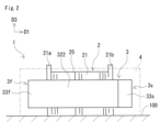
- FIG. 2 is a schematic side view showing the entire reactor of Embodiment 1.
- FIG. 3 is a schematic perspective view showing an exploded state of the reactor of Embodiment 1.
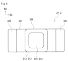
- FIG. 4 is a schematic plan view of the end face of the first core portion provided in the reactor of Embodiment 1, viewed from the first direction.
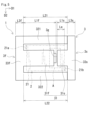
- FIG. 5 is a schematic top view showing the entire reactor of Embodiment 1.
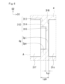
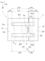
- FIG. FIG. 6 is a schematic enlarged view showing an enlarged area A of FIG.
- FIG. 7 is a schematic top view showing the entire reactor of Embodiment 2.
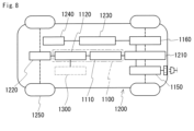
- FIG. FIG. 8 is a configuration diagram schematically showing a power supply system of a hybrid vehicle.
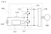
- FIG. 9 is a circuit diagram showing an example of a power conversion device including a converter.
- each inner core piece is configured as a flat surface. That is, a gap portion is provided between two end surfaces that are flat surfaces. If the distance between the two end faces is narrow, it is difficult to fill the space between the two end faces with the mold resin portion. If the amount of the mold resin portion filled between the two end faces is small, it becomes difficult to maintain the above-mentioned distance. If the gap is widened so that the amount of the mold resin portion filled between the two end faces increases, the desired inductance may not be obtained.
- the reactor of the present disclosure has a high filling property of the mold resin portion into the gap portion in the magnetic core and a high inductance.
- a reactor is a coil having a cylindrical winding; a magnetic core having a first core portion and a second core portion combined in the axial direction of the winding portion, and a gap portion provided between the first core portion and the second core portion; a mold resin part covering at least part of the magnetic core, The number of winding parts is one,
- the shape of the first core portion is an E shape
- the shape of the second core portion is T-shaped or E-shaped
- the first core portion is a molded body of a composite material having a first middle core portion disposed inside the winding portion
- the second core portion is a powder compact having a second middle core portion disposed inside the winding portion,
- the gap portion is arranged between an end face of the first middle core portion and an end face of the second middle core portion inside the winding portion,
- the end face of the first middle core portion is an annular outer end surface connected to the outer peripheral surface of the first middle core portion; a peripheral surface extending from the outer end surface toward the end surface of the second middle core portion
- the gap portion provided between the outer end surface and the end surface of the second middle core portion is referred to as the outer gap portion, and is provided between the inner end surface and the end surface of the second middle core portion.
- the gap portion is sometimes called an inner gap portion.
- the above reactor has a high fillability of the mold resin portion into the gap portion.
- the reason is as follows. Part of the constituent material of the mold resin portion is filled inside the wound portion during the molding process of the mold resin portion.
- the outer end surface, the inner end surface, and the end surface of the second middle core portion are flat surfaces. Therefore, the thickness of the outer gap portion is greater than the thickness of the inner gap portion.
- the outer end face is provided annularly. Therefore, the outer gap portion is provided in an annular shape. Since the ratio of the area of the inner end surface to the area of the outer end surface is 1.35 or less, the ratio of the outer gap portion is appropriately ensured. Therefore, the constituent material of the mold resin portion filled inside the wound portion easily spreads between the end face of the first middle core portion and the end face of the second middle core portion.
- the above reactor has high inductance.
- the reason is as follows.
- the length between the inner end face and the end face of the second middle core portion is shorter than the length between the outer end face and the end face of the second middle core portion.
- the above reactor has excellent heat dissipation. This is because heat conduction between the first core portion and the second core portion is likely to be high when the mold resin portion has a portion provided between the outer end face and the end face of the second middle core portion.
- the above reactor has low loss.
- the gap portion is arranged inside the winding portion, it is difficult for leakage magnetic flux to enter the winding portion. Therefore, it is easy to reduce the eddy current loss generated in the winding portion.
- a ratio of the length between the outer end face and the end face of the second middle core portion to the length between the inner end face and the end face of the second middle core portion may be 3.00 or more and 15.00 or less.
- the mold resin portion can be easily filled into the gap portion. This is because the constituent material of the mold resin portion filled inside the wound portion easily spreads between the end face of the first middle core portion and the end face of the second middle core portion.
- the above embodiment with the above ratio of 15.00 or less has a high inductance. This is because the thickness of the outer gap portion is not too large. Also, the above configuration is low loss.
- the axial length of the winding portion of the second middle core portion is shorter than the axial length of the winding portion of the first middle core portion;
- the length from the end surface of the winding portion facing the second core portion to the gap portion may be 0.2 times or more and 0.49 times or less the length of the winding portion.
- the above form has low loss.
- the reason for the above configuration is that the length of the second middle core portion is shorter than the length of the first middle core portion, so that the proportion of the powder compact having a larger loss than that of the composite material compact tends to decrease.
- the gap portion is arranged inside the winding portion, and the length from the end face of the winding portion to the gap portion is 0.2 times or more the length of the winding portion. This makes it difficult for leakage magnetic flux to enter the winding portion. Therefore, it is easy to reduce the eddy current loss generated in the winding portion.
- the length from the end face to the gap portion is 0.49 times or less than the length of the winding portion, so that the composite material with a lower loss than the compacted body is formed inside the winding portion. This is because the proportion of the body can be increased.
- the above form can suppress problems such as affecting peripheral devices due to leakage magnetic flux.
- the gap portion is arranged inside the winding portion, and the length from the end face to the gap portion is 0.2 times or more the length of the winding portion. This is because leakage of the magnetic flux to the outside can be easily suppressed.
- the mold resin portion can be easily filled into the gap portion. Since the length from the end surface to the gap portion is 0.49 times or less the length of the winding portion, the constituent material of the mold resin portion is distributed between the outer end surface and the end surface of the second middle core portion. Because it is easy.
- the gap portion with respect to the total length of the length along the axial direction of the winding portion in the first middle core portion, the length along the axial direction of the winding portion in the second middle core portion, and the thickness of the gap portion may be 0.02 or more and 0.05 or less.
- the thickness of the gap portion here is the length along the axial direction of the winding portion between the outer end surface and the end surface of the second middle core portion. That is, the thickness of the gap portion is the thickness of the outer gap portion.
- the filling property of the mold resin portion into the gap portion is high.
- the above embodiment has a high inductance because the ratio is 0.05 or less.
- the above-described configuration has little leakage magnetic flux and tends to be highly effective in reducing eddy current loss.
- the thickness of the gap portion may be 1.0 mm or more and 2 mm or less.
- the thickness is 1.0 mm or more, so that the mold resin portion can be easily filled into the gap portion.
- Said form has high inductance because said thickness is 2 mm or less.
- the above-described configuration has little leakage magnetic flux and tends to be highly effective in reducing eddy current loss.
- the powder compact is a compact of raw material powder containing soft magnetic powder, A content of the soft magnetic powder in the powder compact may be 85% by volume or more and 99% by volume or less.
- the compacted body described above is more likely to have improved magnetic properties than a compacted body made of a composite material.
- the molded body of the composite material is a molded body in which soft magnetic powder is dispersed in a resin,
- the content of the soft magnetic powder in the compact of the composite material may be 20% by volume or more and 80% by volume or less.
- the above composite material compacts are easier to adjust the magnetic properties of, and are also easier to form into complex shapes.
- a converter according to an aspect of the present disclosure The reactor according to any one of (1) to (7) above is provided.
- the converter has excellent performance because it includes the reactor.
- the power conversion device has excellent performance because it includes the converter.
- FIG. 1 A reactor 1 according to the first embodiment will be described with reference to FIGS. 1 to 6.
- FIG. The reactor 1 includes a coil 2, a magnetic core 3, and a mold resin portion 4, as shown in FIG.
- the coil 2 has a cylindrical winding portion 21 .
- the number of winding parts 21 is one.
- the magnetic core 3 has a first core portion 3f, a second core portion 3s, and a gap portion 3g.
- the first core portion 3 f and the second core portion 3 s are combined in the axial direction of the winding portion 21 .
- the gap portion 3g is provided between the first core portion 3f and the second core portion 3s.
- the mold resin portion 4 covers at least part of the magnetic core 3 .
- One of the features of the reactor 1 of this embodiment is that it satisfies the following requirements (a) to (e).
- the first core portion 3f and the second core portion 3s have a specific shape.
- the first core portion 3f and the second core portion 3s are made of a specific molded body.
- the gap portion 3g is positioned at a specific location.
- Identify the end surface 312 of the first middle core portion 31f provided in the first core portion 3f as shown in FIG. 3 and the end surface 318 of the second middle core portion 31s provided in the second core portion 3s as shown in FIG. is the shape of (e) As shown in FIG. 6, the mold resin portion 4 has a portion provided in a specific region of the gap portion 3g.
- FIG. 5 shows the coil 2 with a two-dot chain line for convenience of explanation.
- a first direction D1, a second direction D2, and a third direction D3 defined as follows may be used.
- the first direction D1 is the direction along the axial direction of the winding portion 21 .
- the second direction D2 is a direction along the parallel direction of a first middle core portion 31f, a first side core portion 321, and a second side core portion 322, which will be described later.
- the third direction D3 is a direction orthogonal to both the first direction D1 and the second direction D2.
- the winding portion 21 of the coil 2 is formed by spirally winding a single wire without joints. Since the number of winding portions 21 is one, the length along the second direction D2 can be shortened compared to the case where a plurality of winding portions are arranged in parallel in the second direction D2.
- the shape of the winding portion 21 of this embodiment is a rectangular tube. Rectangles include rectangles and squares.
- the end face shape of the winding portion 21 of this embodiment is a rectangular frame shape. Since the shape of the winding part 21 is a rectangular cylinder, the contact area between the winding part 21 and the installation target 100 is increased compared to the case where the winding part 21 is a circular cylinder with the same cross-sectional area. easy. Therefore, the reactor 1 easily dissipates heat to the installation target 100 shown in FIG. Moreover, it is easy to stably install the winding part 21 on the installation object 100 .
- the installation target 100 is, for example, a cooling base or an inner bottom surface of a case to be described later.
- the corners of the winding portion 21 are rounded. Unlike the present embodiment, the shape of the winding portion 21 may be a circular cylinder. Circles include perfect circles and ellipses.
- a known winding can be used for the winding.
- the coil of this embodiment uses a covered rectangular wire.
- the conductor wire of the coated rectangular wire is composed of a copper rectangular wire.
- the insulating coating of the coated rectangular wire is made of enamel.
- the wound portion 21 is formed of an edgewise coil obtained by edgewise winding a coated rectangular wire.
- a first end portion 21a and a second end portion 21b of the winding portion 21 extend toward the outer peripheral side of the winding portion 21 at the first end portion and the second end portion of the winding portion 21 in the axial direction, respectively, in the present embodiment. being stretched. Although illustration is omitted, the first end portion 21a and the second end portion 21b have their insulating coatings removed to expose the conductor wires. The exposed conductor wires are pulled out to the outside of the mold resin portion 4, as shown in FIG.
- a terminal member is connected to the exposed conductor wire. Illustration of the terminal member is omitted.
- An external device is connected to the coil 2 through this terminal member. Illustration of the external device is omitted. The external device is, for example, a power source that supplies power to the coil 2 .
- the outer peripheral surface 25 of the winding portion 21 has a portion that contacts the installation target 100 of the reactor 1 . Therefore, the reactor 1 tends to improve heat dissipation.
- the outer peripheral surface 25 has a portion protruding in the third direction D3 from the magnetic core 3 . That is, the length of the wound portion 21 along the third direction D3 is longer than the length of the magnetic core 3 along the third direction D3.
- the outer peripheral surface 25 of the winding portion 21 has four flat surfaces. In this embodiment, one of the four flat surfaces is the portion that contacts the installation target 100 . Therefore, the winding portion 21 can secure a sufficient contact area with the installation target 100 . Therefore, the reactor 1 tends to further improve heat dissipation.
- the contact portion of the winding portion 21 is exposed from the mold resin portion 4, which will be described later. Therefore, the heat of the coil 2 is easily released through the installation target 100 .
- the magnetic core 3 is, as shown in FIG. 1, a combination in which a first core portion 3f and a second core portion 3s are combined in the first direction D1. Since the magnetic core 3 can be constructed by combining the first core portion 3f and the second core portion 3s in the first direction D1, the reactor 1 is excellent in manufacturing workability. A gap portion 3g, which will be described later, is provided between the first core portion 3f and the second core portion 3s.
- the combination of the first core portion 3f and the second core portion 3s is ET type in this embodiment. Unlike the present embodiment, the above combination may be type EE. These combinations are easier to adjust inductance and heat dissipation.
- the first core portion 3f is made of a molded composite material, which will be described later.
- the second core portion 3s is composed of a compacted body to be described later.
- the total volume Va of the volume of the first core portion 3f, the volume of the second core portion 3s, and the volume of the gap portion 3g is 50 cm 3 or more and 500 cm 3 or less.
- a reactor 1 having a total volume V of 50 cm 3 or more and 500 cm 3 or less is suitable for a converter of an electric vehicle, a hybrid vehicle, or a fuel cell vehicle. Even if the total volume Va is 50 cm 3 or more, the magnetic core The heat of 3 is easily released. When the total volume Va is 500 cm 3 or less, the reactor 1 is unlikely to become excessively large.
- the total volume Va is further 60 cm 3 or more and 400 cm 3 or less, particularly 70 cm 3 or more and 300 cm 3 or less.
- the volume of the gap portion 3g is the volume of the space surrounded by the end surface 312 of the first middle core portion 31f, the end surface 318 of the second middle core portion 31s, and the virtual outer peripheral surface.
- the imaginary outer peripheral surface is an outer peripheral surface obtained by extending the outer peripheral surface 311 of the first middle core portion 31f in the first direction D1.
- the planar shape of the first core portion 3f is an E shape as shown in FIG.
- the planar shape of the first core portion 3f refers to the shape of the first core portion 3f viewed from the third direction D3.
- the concept of the planar shape is the same for the second core portion 3s, which will be described later.
- the first core portion 3 f has a first end core portion 33 f , a first middle core portion 31 f , a first side core portion 321 and a second side core portion 322 .
- the first end core portion 33f and the first end face of the winding portion 21 face each other.
- the first middle core portion 31 f has a portion arranged inside the winding portion 21 .
- the first side core portion 321 and the second side core portion 322 are arranged to face each other so as to sandwich the first middle core portion 31f.
- the first side core portion 321 and the second side core portion 322 are arranged on the outer circumference of the winding portion 21 .
- the first core portion 3f is a molded body in which a first end core portion 33f, a first middle core portion 31f, a first side core portion 321 and a second side core portion 322 are integrated.
- the first end core portion 33 f connects the first middle core portion 31 f, the first side core portion 321 and the second side core portion 322 .
- the first side core portion 321 and the second side core portion 322 are provided at both ends of the first end core portion 33f.
- the first middle core portion 31f is provided in the center of the first end core portion 33f.
- the shape of the first end core portion 33f is a thin prismatic shape in this embodiment.
- the first side core portion 321 and the second side core portion 322 have the same shape.
- the shape of the first side core portion 321 and the second side core portion 322 is a thin prismatic shape.
- the shape of the first middle core portion 31f is a shape corresponding to the inner peripheral shape of the winding portion 21.
- the shape of the first middle core portion 31f of this embodiment is a quadrangular prism.
- the first middle core portion 31f has an outer peripheral surface 311 and an end surface 312, as shown in FIG.
- the outer peripheral surface 311 is a surface facing the inner peripheral surface of the winding portion 21 . 3, the corners of the outer peripheral surface 311 are rounded along the inner peripheral surface of the corners of the winding portion 21 as shown in FIG.
- the end surface 312 has an outer end surface 313, a peripheral surface 314, and an inner end surface 315, as shown in FIGS.
- the outer end surface 313 is connected to the outer peripheral surface 311 .
- the outer end surface 313 is an annular flat surface.
- the outer end surface 313 of the present embodiment is a rectangular annular flat surface, as shown in FIG.
- Peripheral surface 314 is connected to outer end surface 313 and inner end surface 315 as shown in FIGS.
- Peripheral surface 314 is a cylindrical surface extending from outer end surface 313 toward end surface 318 .
- the peripheral surface 314 of this embodiment is a rectangular cylindrical surface.
- the peripheral surface 314 may be a cylindrical surface linearly extending along the first direction D ⁇ b>1 or may be a cylindrical surface tapering from the outer end surface 313 toward the inner end surface 315 .
- the inner end surface 315 is a flat surface.
- the planar shape of the inner end surface 315 of this embodiment is similar to the contour shape of the outer peripheral surface 311, as shown in FIG. That is, the planar shape of the inner end surface 315 of the present embodiment is square. Unlike this embodiment, the planar shape of the inner end surface 315 may be a shape different from the contour shape of the outer peripheral surface 311 .
- the planar shape of the inner end face 315 of this embodiment may be circular. Since the outer end surface 313, the inner end surface 315, and the end surface 318 are flat surfaces, as shown in FIG. and the end surface 318 along the first direction D1. In other words, length Lgi is shorter than length Lge.
- the ratio of the area Si of the inner end face 315 to the area Se of the outer end face 313, that is, the area Si/area Se is 0.30 or more and 1.35 (see FIG. 4).
- the reactor 1 in which the ratio of area Si/area Se is 0.30 or more has high inductance. This is because the ratio of the area Si/area Se of 0.30 or more ensures an appropriate ratio of the inner gap portion 3gi, which will be described later with reference to FIG.
- the reactor 1 in which the area Si/area Se is 1.35 or less has a high filling property of the mold resin portion 4 into the gap portion 3g. The reason is as follows. Part of the constituent material of the mold resin portion 4 is filled inside the wound portion 21 during the molding process of the mold resin portion 4 .
- An outer gap portion 3ge which will be described later with reference to FIG. 6, is provided in an annular shape. Since the area Si/area Se is 1.35 or less, the ratio of the outer gap portion 3ge is properly ensured. Therefore, the constituent material of the mold resin portion 4 filled in the inside of the winding portion 21 spreads easily between the end surface 312 and the end surface 318 .
- Area Si/area Se may be 0.31 or more and 1.25 or less, or may be 0.32 or more and 1.15 or less.
- Area Si/area Se may be 0.32 or more and 1.00 or less, or may be 0.32 or more and 0.85 or less.
- the total cross-sectional area of the first side core portion 321 and the cross-sectional area of the second side core portion 322 in this embodiment is the same as the cross-sectional area of each of the cross-sectional areas of the first middle core portion 31f and the second middle core portion 31s. is.
- the cross-sectional area referred to here is the cross-sectional area of a cross section orthogonal to the first direction D1.
- the length L1f of the first middle core portion 31f along the first direction D1 is shorter than the length of the winding portion 21 along the first direction D1.
- the length L1f is the length along the first direction D1 between the portion of the first middle core portion 31f connected to the first end core portion 33f and the inner end face 315 .
- the length along the first direction D1 of the winding portion 21 is the length along the first direction D1 between the first end surface and the second end surface of the winding portion 21 . If there are gaps between the turns of the wound portion 21, the length of the wound portion 21 along the first direction D1 includes the length of the gaps between the turns.
- the length of the first middle core portion 31f along the second direction D2 is the length of each of the length of the first side core portion 321 along the second direction D2 and the length of the second side core portion 322 along the second direction D2. Longer than length. As shown in FIG. 1, the length of the first middle core portion 31f along the third direction D3 is equal to the length of the first side core portion 321 along the third direction D3 and the length of the second side core portion 322 along the third direction D3. Identical to each of the lengths along.
- the length L21 of the first side core portion 321 along the first direction D1 and the length L22 of the second side core portion 322 along the first direction D1 are the same.
- the length L21 and the length L22 are longer than the length L1f and longer than the length of the wound portion 21 along the first direction D1.
- the length of the first side core portion 321 along the second direction D2 and the length of the second side core portion 322 along the second direction D2 are the same.
- the length of the first side core portion 321 along the third direction D3 and the length of the second side core portion 322 along the third direction D3 are the same.
- the planar shape of the second core portion 3s is T-shaped in this embodiment. Unlike the present embodiment, the planar shape of the second core portion 3s may be an E shape. As described above, the second core portion 3s is made of a compacted body. A compacted body having a T-shaped planar shape is easier to manufacture than a compacted body having an E-shaped planar shape. Therefore, a compacted body having a T-shaped planar shape is easier to manufacture with high precision than a compacted body having an E-shaped planar shape. Therefore, when the second core portion 3s having a T-shaped planar shape is combined with the first core portion 3f, an unnecessary gap is less likely to be provided, compared to the case where the planar shape is E-shaped.
- the second core portion 3s of the present embodiment has a second end core portion 33s and a second middle core portion 31s.
- the second end core portion 33s and the second end surface of the winding portion 21 face each other.
- the second middle core portion 31 s has a portion arranged inside the winding portion 21 .
- the second core portion 3s is a molded body in which a second end core portion 33s and a second middle core portion 31s are integrated.
- the second middle core portion 31s is provided in the center of the second end core portion 33s.
- the shape of the second end core portion 33s is the same as the shape of the first end core portion 33f. That is, the second end core portion 33s has a thin prismatic shape.
- the shape of the second middle core portion 31s is a quadrangular prism.
- the corners of the second middle core portion 31 s are rounded along the inner peripheral surface of the corners of the winding portion 21 .
- An end surface 318 of the second middle core portion 31s is a flat surface.
- the length L1s of the second middle core portion 31s along the first direction D1 is shorter than the length L1f.
- the total length of length L1s and length L1f is shorter than each length of length L21 and length L22.
- the length of the second middle core portion 31s along the second direction D2 is the same as the length of the first middle core portion 31f along the second direction D2.
- the length of the second middle core portion 31s along the third direction D3 is the same as the length of the first middle core portion 31f along the third direction D3.
- the length L3s of the second end core portion 33s along the first direction D1 is the same as the length L3f of the first end core portion 33f along the first direction D1.
- the length of the second end core portion 33s along the second direction D2 is the same as the length of the first end core portion 33f along the second direction D2.
- the length of the second end core portion 33s along the second direction D2 is longer than the length of the winding portion 21 along the second direction D2.
- the length of the second end core portion 33s along the third direction D3 is the same as the length of the first end core portion 33f along the third direction D3.
- the length of the second end core portion 33s along the third direction D3 is shorter than the length of the winding portion 21 along the third direction D3. As shown in FIG. 1, the length of the second end core portion 33s along the third direction D3 is the same as the length of the second middle core portion 31s along the third direction D3.
- volume ratio Vps obtained by (volume Vs/total volume Va) ⁇ 100 is 25% or more and 40% or less.
- the volume Vs is the volume of the second core portion 3s.
- the total volume Va is the total volume of the volume of the first core portion 3f, the volume of the second core portion 3s, and the volume of the gap portion 3g, as described above. If the volume ratio Vps is 25% or more, the heat dissipation of the reactor 1 tends to be high. If the volume ratio Vps is 40% or less, the loss of the reactor 1 tends to decrease.
- the volume ratio Vps may be 27% or more and 38% or less, or may be 29% or more and 36% or less.
- volume ratio Vpm obtained by (volume Vms/total volume Vma) ⁇ 100 is 15% or more and 49% or less.
- the volume Vms is the volume of the second middle core portion 31s.
- the total volume Vma is the sum of the volume of the first middle core portion 31f, the volume of the second middle core portion 31s, and the volume of the gap portion 3g. If the ratio Vpm is 15% or more, the heat dissipation of the reactor 1 tends to be high. If the ratio Vpm is 49% or less, the loss of the reactor 1 tends to decrease.
- the ratio Vpm may be 20% or more and 40% or less, or may be 25% or more and 35% or less.
- the first core portion 3f and the second core portion 3s are combined so that the end face of the first side core portion 321, the end face of the second side core portion 322 and the end face of the second end core portion 33s are in contact with each other.
- a gap is provided between the end face 312 of the first middle core portion 31f and the end face 318 of the second middle core portion 31s.
- a gap portion 3g which will be described later, is provided between the end face 312 and the end face 318.
- the molded body of the composite material that constitutes the first core portion 3f is a molded body in which soft magnetic powder is dispersed in resin.
- a molded body of composite material is obtained by filling a mold with a fluid material in which soft magnetic powder is dispersed in unsolidified resin and solidifying the resin.
- the molded body of the composite material can easily adjust the content of the soft magnetic powder in the resin. Therefore, it is easy to adjust the magnetic properties of the molded body of the composite material.
- composite material compacts are easier to form even in complicated shapes than powder compacts.
- An example of the content of the soft magnetic powder in the compact of the composite material is 20% by volume or more and 80% by volume or less.
- An example of the resin content in the molded composite material is 20% by volume or more and 80% by volume or less.
- the compacted body that constitutes the second core portion 3s is a compacted body obtained by compression-molding soft magnetic powder.
- the powder compact can have a higher ratio of the soft magnetic powder in the core portion than the composite material compact. Therefore, it is easy to improve the magnetic properties of the powder compact. Magnetic properties include relative magnetic permeability and saturation magnetic flux density.
- the powder compact has a smaller amount of resin and a larger amount of soft magnetic powder than a compact made of composite material, and is therefore excellent in heat dissipation.
- An example of the magnetic powder content in the powder compact is 85% by volume or more and 99% by volume or less. This content is a value when the powder compact is 100% by volume.
- the particles that make up the soft magnetic powder are soft magnetic metal particles, coated particles, or soft magnetic non-metal particles.
- the coated particles include soft magnetic metal particles and an insulating coating provided on the outer periphery of the soft magnetic metal particles.
- the soft magnetic metal is pure iron, an iron-based alloy, or the like. Iron-based alloys are, for example, Fe—Si alloys or Fe—Ni alloys.
- the insulating coating is, for example, phosphate.
- a soft magnetic non-metal is, for example, ferrite.
- the resin of the molded composite material is, for example, a thermosetting resin or a thermoplastic resin.
- Thermosetting resins are, for example, epoxy resins, phenolic resins, silicone resins, or urethane resins.
- Thermoplastic resins are, for example, polyphenylene sulfide resins, polyamide resins, liquid crystal polymers, polyimide resins, or fluorine resins.
- Polyamide resins are, for example, nylon 6, nylon 66, or nylon 9T.
- the molded body of the composite material may contain ceramic filler.
- a ceramic filler is, for example, alumina or silica.
- a ceramic filler contributes to improvement in heat dissipation and electrical insulation.
- the content of the soft magnetic powder in the molded body of the composite material and the content of the soft magnetic powder in the compacted body are regarded as equivalent to the area ratio of the soft magnetic powder in the cross section of the molded body.
- the content of the soft magnetic powder in the compact is determined as follows. A cross section of the compact is observed with an SEM (scanning electron microscope) to obtain an observed image.
- the cross section of the molded article is any cross section.
- the magnification of the SEM is 200 times or more and 500 times or less.
- the number of acquired observation images is set to 10 or more.
- the total cross-sectional area shall be 0.1 cm 2 or more.
- One observation image may be acquired for one cross section, or a plurality of observation images may be acquired for one cross section.
- Image processing is performed on each acquired observation image to extract the outline of the particle.
- the image processing is, for example, binarization processing.
- the area ratio of the soft magnetic particles is calculated in each observation image, and the average value of the area ratios is obtained.
- the average value is regarded as the content of the soft magnetic powder.
- the first core portion 3f is made of a composite material compact and the second core portion 3s is made of a powder compact, it is easy to adjust the inductance without passing through the long gap portion 3g. In addition, it is easy to adjust the heat dissipation. And the reactor 1 is easy to raise heat dissipation because the second core part 3s is comprised with the compacting body with a comparatively high thermal conductivity.
- the position where the gap portion 3 g is arranged is inside the winding portion 21 .
- the gap portion 3g is arranged between the end face 312 of the first middle core portion 31f and the end face 318 of the second middle core portion 31s. Since the gap portion 3 g is provided inside the winding portion 21 , leakage magnetic flux is less likely to enter the winding portion 21 than when the gap portion 3 g is provided outside the winding portion 21 . Therefore, it is easy to reduce the eddy current loss generated in the winding portion 21 .
- the gap portion 3g has an outer gap portion 3ge and an inner gap portion 3gi.
- Outer gap portion 3ge is provided between outer end face 313 and end face 318 .
- the inner gap portion 3gi is provided between the inner end face 315 and the end face 318 .
- the gap portion 3g is made of a material having a smaller relative magnetic permeability than the first core portion 3f and the second core portion 3s. At least a portion of the gap portion 3g is composed of a portion of the mold resin portion 4, which will be described later.
- the gap portion 3g may be composed only of the mold resin portion 4, or may be composed of the mold resin portion 4 and an air gap.
- the outer gap portion 3ge is composed of the molded resin portion 4
- the inner gap portion 3gi is substantially composed of an air gap.
- An example of the ratio of the thickness of the outer gap portion 3ge to the thickness of the inner gap portion 3gi is 3.00 or more and 15.00 or less.
- the thickness of the inner gap portion 3gi is the length Lgi.
- the thickness of the outer gap portion 3ge is the length Lge. That is, the ratio of the thickness of the outer gap portion 3ge to the thickness of the inner gap portion 3gi is length Lge/length Lgi.
- the reactor 1 in which the length Lge/length Lgi is 3.00 or more has a high fillability of the mold resin portion 4 into the gap portion 3g.
- a reactor 1 having a ratio of length Lge/length Lgi of 15.00 or less has high inductance.
- the reactor 1 whose length Lge/length Lgi is 3.00 or more and 15.00 or less has a low loss.
- the length Lge/length Lgi may be 3.25 or more and 12.50 or less, or may be 3.50 or more and 10.00 or less.
- the length Lge/length Lgi may be 3.50 or more and 7.00 or less.
- An example of the ratio of the thickness of the gap portion 3g to the total length of the length L1f, the length L1s, and the thickness of the gap portion 3g is 0.02 or more and 0.05 or less.
- the thickness of the gap portion 3g is the length Lge. If the above ratio is 0.02 or more, the fillability of the mold resin portion 4 into the gap portion 3g is high. If the above ratio is 0.05 or less, it is easy to secure a predetermined inductance. In addition, there is little leakage magnetic flux, and the effect of reducing eddy current loss tends to be high.
- the above ratio may be 0.02 or more and 0.04 or less, or may be 0.02 or more and 0.035 or less.
- the length Lge is 1.0 mm or more and 2 mm or less. If the length Lge is 1.0 mm or more, the filling property of the mold resin portion 4 into the gap portion 3g is high. If the length Lge is 2 mm or less, it is easy to secure a predetermined inductance. In addition, there is little leakage magnetic flux, and the effect of reducing eddy current loss tends to be high.
- the length Lge may be more than 1.0 mm and 2 mm or less, 1.2 mm or more and 1.75 mm or less, or 1.25 mm or more and 1.5 mm or less.
- An example of the length Le along the first direction D1 from the second end surface of the winding portion 21 to the gap portion 3g is 0.2 times or more the length of the winding portion 21 along the first direction D1. .49 times or less.
- the length Le is the length along the first direction D1 between the position of the gap portion 3g closest to the second end surface and the second end surface. That is, the length Le is the length along the first direction D1 between the end surface 318 shown in FIG. 6 and the second end surface.
- the length Le is 0.2 times or more the length of the winding portion 21 along the first direction D1
- the reactor 1 has a low loss. Moreover, if the length Le is 0.49 times or less the length of the winding portion 21 along the first direction D1, the volume of the first middle core portion 31f is larger than the volume of the second middle core portion 31s inside the winding portion 21. volume tends to be large. Therefore, since the volume of the first core portion 3f is likely to be larger than the volume of the second core portion 3s, the ratio of the low-loss composite material compact is likely to be greater than that of the powder compact. Therefore, the reactor 1 has a low loss. Moreover, if the length Le is 0.49 times or less the length along the first direction D1 of the wound portion 21, at least a portion of the gap portion 3g can be easily formed from a portion of the mold resin portion 4.
- the length Le is 0.49 times or less the length of the winding portion 21 along the first direction D1, even if the total volume Va is 50 cm 3 or more, The constituent material of the mold resin portion 4 is easily distributed. The shorter the length Le, the easier it is for the constituent material of the mold resin portion 4 to spread between the end surfaces 312 and 318 .
- the length Le may be 0.2 times or more and 0.4 times or less the length of the winding portion 21 along the first direction D1. It may be 0.25 times or more and 0.375 times or less of the height.
- a ratio of the length Lt to the length Lc is 0.05 or more and 0.5 or less, and further 0.1 or more and 0.35 or less.
- the length Lc is the inner dimension of the winding portion 21 along the third direction D3.
- the length Lt is the sum of the length Lu and the length Ld.
- the length Lu is the length along the third direction D3 between the upper surfaces of the first middle core portion 31f and the second middle core portion 31s and the inner peripheral surface of the winding portion 21 .
- the length Ld is the length along the third direction D3 between the lower surfaces of the first middle core portion 31f and the second middle core portion 31s and the inner peripheral surface of the winding portion 21 .
- the upper surface is a surface far from the installation target 100 of the first middle core portion 31f and the second middle core portion 31s.
- the lower surface is the surface near the installation target 100 of the first middle core portion 31f and the second middle core portion 31s.
- the distance between the inner peripheral surface of the winding portion 21 and the outer peripheral surfaces of the first middle core portion 31f and the second middle core portion 31s may be substantially uniform in the circumferential direction.
- An example of the distance between the inner peripheral surface of the winding portion 21 and the outer peripheral surfaces of the first middle core portion 31f and the second middle core portion 31s is 1.0 mm or more and 5.0 mm or less, and further 1.5 mm or more. 0 mm or less. This interval is the minimum interval.
- the mold resin portion 4 covers at least part of the magnetic core 3 as shown in FIG. 1, and constitutes at least part of the gap portion 3g as shown in FIG.
- the mold resin portion 4 may cover the outer circumference of the magnetic core 3 and may not cover the outer circumference of the coil 2 , or may cover both the outer circumference of the magnetic core 3 and the outer circumference of the coil 2 .
- FIG. 5 omits the molded resin portion 4 for convenience of explanation.
- the molded resin portion 4 of the present embodiment covers the outer circumference of the assembly of part of the coil 2 and the magnetic core 3 . Therefore, the assembly is substantially protected from the external environment.
- the flat surface of the outer peripheral surface 25 that is close to the installation target is exposed from the mold resin portion 4 .
- a surface of the outer peripheral surface 25 excluding a flat surface close to the installation target is covered with the mold resin portion 4 .
- the entire outer circumference of the magnetic core 3 is covered with the mold resin portion 4 .
- the molded resin portion 4 is provided between the winding portion 21 and the first middle core portion 31f and between the winding portion 21 and the second middle core portion 31s. Furthermore, the mold resin portion 4 is provided at least partly between the end surfaces 312 and 318 .
- the mold resin portion 4 is provided between the outer end surface 313 and the end surface 318 as shown in FIG. Since the molded resin portion 4 has a portion provided between the outer end surface 313 and the end surface 318, the heat conduction between the first core portion 3f and the second core portion 3s tends to be high. Excellent heat dissipation.
- the molded resin portion 4 is substantially not provided between the inner end face 315 and the end face 318 .
- the coil 2 and the magnetic core 3 are integrated by the molded resin portion 4 .
- the resin of the mold resin portion 4 is, for example, the same resin as the resin of the molded composite material described above.
- the resin of the mold resin portion 4 may contain a ceramic filler as in the case of the molded body of the composite material.
- the reactor 1 may include at least one of a case, an adhesive layer, and a holding member.
- the case accommodates an assembly of the coil 2 and the magnetic core 3 inside.
- the combined body in the case may be embedded in the sealing resin portion.
- the case is installed on a cooling base or the like.
- the adhesive layer fixes the assembly to the cooling base or the inner bottom surface of the case, or fixes the case to the cooling base or the like.
- the holding member is provided between the coil 2 and the magnetic core 3 to ensure insulation between the coil 2 and the magnetic core 3 .
- the reactor 1 has a high filling property of the mold resin portion 4 into the gap portion 3g.
- the ratio of area Si/area Se is 1.35 or less and the ratio of length Lge/length Lgi is 3.00 or more, the constituent material of the mold resin portion 4 filled inside the winding portion 21 does not reach the end surface 312 . and the end surface 318.
- Reactor 1 has high inductance. This is because the ratio of the inner gap portion 3gi is appropriately ensured when the ratio of area Si/area Se is 0.30 or more. Also, the length Lge/length Lgi is 15.00 or less so that the length Lge is not too large.
- the reactor 1 has excellent heat dissipation. This is because the heat of the coil 2 can be effectively radiated through the installation target 100 by including a portion in which the winding part 21 is in contact with the installation target 100 as shown in FIG. 2 . Further, as shown in FIG. 6, the mold resin portion 4 has a portion provided between the outer end surface 313 and the end surface 318, so that heat conduction between the first core portion 3f and the second core portion 3s This is because the
- Reactor 1 has low loss. This is because when the length L1s is shorter than the length L1f, the ratio of the powder compact having a larger loss than that of the composite material compact is small. Further, since the gap portion 3g is arranged inside the winding portion 21 and the length Le is 0.2 times or more the length of the winding portion 21, leakage magnetic flux does not enter the winding portion 21. hard. Therefore, the eddy current loss generated in the winding portion 21 can be easily reduced. Furthermore, the length Le is 0.49 times or less the length of the winding portion 21, so that the proportion of the composite material molded body having a lower loss than the compacted body is increased inside the wound portion 21. Because you can.
- a reactor 1 according to the second embodiment will be described with reference to FIG.
- the reactor 1 of the present embodiment differs from the reactor 1 of the first embodiment in that the combination of the first core portion 3f and the second core portion 3s is an EE type. That is, the planar shape of the first core portion 3f and the planar shape of the second core portion 3s of the present embodiment are E-shaped.
- the following description will focus on the differences from the first embodiment. A description of the configuration similar to that of the first embodiment is omitted.
- the first core portion 3f of the present embodiment has a first end core portion 33f, a first middle core portion 31f, a first side core portion 321f, and a second side core portion 322f.
- the length L21f of the first side core portion 321f and the length L22f of the second side core portion 322f are equal to the length L21 and the second side core portion of the first side core portion 321f of the first embodiment.
- 322 is shorter than the length L22, which is different from the first embodiment.
- the second core portion 3s of the present embodiment has a second end core portion 33s, a second middle core portion 31s, a first side core portion 321s, and a second side core portion 322s.
- the second core portion 3s is a molded body in which a second end core portion 33s, a second middle core portion 31s, a first side core portion 321s, and a second side core portion 322s are integrated.
- the second end core portion 33s connects the second middle core portion 31s, the first side core portion 321s, and the second side core portion 322s.
- the first side core portion 321s and the second side core portion 322s are provided at both ends of the second end core portion 33s.
- the second middle core portion 31s is provided in the center of the second end core portion 33s.
- the shape of the first side core portion 321s and the second side core portion 322s is a thin prismatic shape.
- the first core portion 3f and the second core portion 3s are different in size.
- the length L21f along the first direction D1 of the first side core portion 321f and the length L22f along the first direction D1 of the second side core portion 322f are the same.
- Length L21f and length L22f are longer than length L1f.
- the length L21s along the first direction D1 of the first side core portion 321s and the length L22s along the first direction D1 of the second side core portion 322s are the same.
- Length L21s and length L22s are longer than length L1s.
- Length L1f is longer than length L1s.
- Length L21f is longer than length L21s, and length L22f is longer than length L22s.
- the length L3f and the length L3s are the same as each other.
- the lengths of the first middle core portion 31f and the second middle core portion 31s along the second direction D2 are the same.
- the first side core portion 321f, the first side core portion 321s, the second side core portion 322f, and the second side core portion 322s have the same length along the second direction D2.
- the first end core portion 33f and the second end core portion 33s have the same length along the second direction D2.
- Each core portion has the same length along the third direction D3.
- the length of each core portion along the third direction D3 is shorter than the length of the winding portion 21 along the third direction D3.
- the first core portion 3f and the second core portion 3s are defined by the end surfaces of the first side core portion 321f and the second side core portion 322f, the end surfaces of the first side core portion 321s and the end surfaces of the second side core portion 322s, respectively. are combined so that they are in contact with each other.
- a gap portion 3g is provided between the end face of the first middle core portion 31f and the end face of the second end core portion 33s.
- the reactor 1 of this embodiment has a high fillability of the mold resin portion 4 into the gap portion 3g. Also, the reactor 1 has a high inductance. Furthermore, the reactor 1 is excellent in heat dissipation. And the reactor 1 has a low loss.
- the reactors 1 of Embodiments 1 and 2 can be used for applications that satisfy the following energization conditions.
- the energization conditions are, for example, a maximum DC current of approximately 100 A or more and 1000 A or less, an average voltage of approximately 100 V or more and 1000 V or less, and a working frequency of approximately 5 kHz or more and 100 kHz or less.
- the reactor 1 of Embodiments 1 and 2 is typically used as a component of a converter installed in a vehicle 1200 such as an electric vehicle, a hybrid vehicle, or a fuel cell vehicle, or a component of a power conversion device including this converter. can.
- the vehicle 1200 includes a main battery 1210, a power conversion device 1100 connected to the main battery 1210, and a motor 1220 that is driven by power supplied from the main battery 1210 and used for running.
- Motor 1220 is typically a three-phase AC motor.
- Motor 1220 drives wheels 1250 during running, and functions as a generator during regeneration.
- vehicle 1200 includes engine 1300 in addition to motor 1220 .
- FIG. 8 shows an inlet as the charging point of vehicle 1200, it can be configured to include a plug.
- a power conversion device 1100 has a converter 1110 connected to a main battery 1210, and an inverter 1120 connected to the converter 1110 for mutual conversion between direct current and alternating current.
- Converter 1110 shown in this example boosts the input voltage of main battery 1210 from approximately 200 V to 300 V to approximately 400 V to 700 V and supplies power to inverter 1120 when vehicle 1200 is running.
- converter 1110 steps down the input voltage output from motor 1220 via inverter 1120 to a DC voltage suitable for main battery 1210 to charge main battery 1210 .
- the input voltage is a DC voltage.
- Inverter 1120 converts the direct current boosted by converter 1110 into a predetermined alternating current and supplies power to motor 1220 when vehicle 1200 is running, and converts the alternating current output from motor 1220 into direct current during regeneration and outputs the direct current to converter 1110. are doing.
- the converter 1110 includes a plurality of switching elements 1111, a drive circuit 1112 that controls the operation of the switching elements 1111, and a reactor 1115, as shown in FIG. 9, and converts the input voltage by repeating ON/OFF. Conversion of the input voltage means stepping up and down in this case.
- a power device such as a field effect transistor or an insulated gate bipolar transistor is used for the switching element 1111 .
- the reactor 1115 has a function of smoothing the change when the current increases or decreases due to the switching operation by using the property of the coil that prevents the change of the current to flow in the circuit.
- the reactor 1 of the first embodiment is provided as the reactor 1115 . By providing the reactor 1, the power conversion device 1100 and the converter 1110 have excellent performance.
- vehicle 1200 is connected to power feed device converter 1150 connected to main battery 1210, sub-battery 1230 serving as a power source for auxiliary equipment 1240, and main battery 1210 to supply the high voltage of main battery 1210.
- An accessory power supply converter 1160 for converting to low voltage is provided.
- Converter 1110 typically performs DC-DC conversion, but power supply device converter 1150 and auxiliary power supply converter 1160 perform AC-DC conversion. Some power supply converters 1150 perform DC-DC conversion.
- a reactor having the same configuration as the reactor 1 of the first embodiment, etc., and having the size and shape changed appropriately can be used as the reactor of the power supply device converter 1150 and the auxiliary power converter 1160 .
- the reactor 1 of the first embodiment can be used for a converter that converts input power and only boosts or only steps down.
- an analysis model was evaluated in which a reactor was constructed on simulation software and area Si/area Se and length Lge/length Lgi were set.
- Sample no. 1 to sample no. 16 Sample no. 1 to sample no. As the 16 analytical models, a combination of a coil 2 and a magnetic core 3 as shown in FIG. 1 was constructed. That is, the analysis model of each sample does not have the mold resin portion 4 as shown in FIG.
- the end face of the first middle core portion 31f in each sample was the same end face as the end face 312 having the outer end face 313, the peripheral face 314 and the inner end face 315 described with reference to FIG.
- Table 1 or Table 2 the shape of the inner end surface of each sample was a perfect circle or a square. Sample no. 2 to sample no. The four corners of the inner end face and the four corners of the outer end face at 16 are rounded.
- Table 1 or Table 2 shows the area Si, area Se, and area Si/area Se in each sample.
- the area Si is the area of the inner end surface
- the area Se is the area of the outer end surface.
- the ratio of area Si/area Se was adjusted.
- Area Si/area Se in each table is rounded off to the third decimal place.
- Table 1 or Table 2 shows the length Lge, length Lgi, and length Lge/length Lgi for each sample.
- the length Lge is the thickness of the outer gap portion and the length Lgi is the thickness of the inner gap portion.
- the length Lge/length Lgi was adjusted by adjusting the length of the peripheral surface.
- the length Lge/length Lgi of each table is rounded off to the third decimal place.
- the length Le of each sample satisfies 0.2 times or more and 0.49 times or less of the length along the first direction D1 of the winding portion 21 .
- the ratio of the length Lge to the total length of the length L1f, the length L1s and the length Lge in each sample satisfied 0.02 or more and 0.05 or less.
- the ratio of length Lt to length Lc (Lt/Lc) was about 0.14.
- the distance between the inner peripheral surface of the winding portion 21 and the outer peripheral surfaces of the first middle core portion 31f and the second middle core portion 31s was about 2.5 mm.
- Sample no. 100 is the same as sample No. 100 except that the end surface of the first middle core portion 31f is flat and the thickness of the gap portion is 1.0 mm. 1 and so on.
- the analysis software includes electromagnetic field analysis software JMAG-Designer Ver. 20.1 was used.
- the analysis method is magnetic field transient response analysis (solution method: A- ⁇ method 2).
- the maximum value of the inductance of sample No. 7 is It is equal to or greater than the maximum value of inductance of sample No. 100. 1 to sample no. It was large compared to the maximum value of the inductance of No. 3.
- the loss of the coil of sample No. 7 is The loss is equal to or lower than that of the sample No. 100 coil. 1 to sample no. It was small compared to the loss of the coil of No. 3.
- the maximum value of the inductance of sample No. 11 is It is equal to or greater than the maximum value of inductance of sample No. 100. 12 to sample no. It was large compared to the maximum value of 16 inductances.
- Sample no. 9 to sample no. The loss of the coil of sample no. The loss is equal to or lower than that of the sample No. 100 coil. 12 to sample no. It was small compared to the loss of 16 coils.
- the total loss of 11 is greater than that of sample no. 12 to sample no. 16, and sample no. Equivalent to an overall loss of 100.
- the fillability of the mold resin part into the gap part was investigated using the resin flow analysis software Moldex 3D Studio 2020 manufactured by JSOL Corporation.
- the mold resin portion was made of polyphenylene sulfide resin containing glass fiber fibers.
- the constituent material of the mold resin portion was filled from the outside of the assembly toward the inside of the wound portion 21 .
- the fillability of the resin between the end face of the first middle core portion 31f and the end face of the second middle core portion 31s was visually confirmed together with the contour drawing.
- the larger the area Se the larger the filling amount of the mold resin portion in the outer gap portion.
- sample no. 1 to sample no. 7, and sample no. 9 to sample no. 16 is sample no.
- the filling amount of the mold resin portion in the outer gap portion was large.
- sample no. 1 to No. 16 the inner gap portion was not substantially filled with the mold resin portion.
- Sample no. In 100 the mold resin portion was not substantially filled in the gap portion.
- sample No. 4 to sample no. 7, and sample no. 9 to sample no. No. 11 was found to have a high fillability of the mold resin portion in the gap portion and a high inductance.
Landscapes
- Engineering & Computer Science (AREA)
- Power Engineering (AREA)
- Coils Or Transformers For Communication (AREA)
- Insulating Of Coils (AREA)
Abstract
Un réacteur selon l'invention est équipé : d'une bobine comportant une partie enroulement ; d'un noyau magnétique comportant une première section de noyau en forme de E, une seconde section de noyau en forme de T ou en forme de E, et une section d'espacement ; et d'une section en résine moulée. La première section de noyau est un corps moulé en matériau composite comportant une première section de noyau central ; la seconde section de noyau est un corps moulé en poudre comprimée comportant une seconde section de noyau central ; la section d'espacement est positionnée entre la surface d'extrémité de la première section de noyau central et la surface d'extrémité de la seconde section de noyau central à l'intérieur de la partie enroulement ; la surface d'extrémité de la première section de noyau central comporte une surface d'extrémité extérieure en forme d'anneau, une surface circonférentielle et une surface d'extrémité intérieure ; la surface d'extrémité de la seconde section de noyau central, la surface d'extrémité extérieure et la surface d'extrémité intérieure sont des surfaces plates ; le rapport de la superficie de la surface d'extrémité intérieure à la superficie de la surface d'extrémité extérieure est de 0,30 à 1,35 inclus ; et la section de résine moulée comporte une section disposée entre la surface d'extrémité extérieure et la surface d'extrémité de la seconde section de noyau central.
Priority Applications (1)
| Application Number | Priority Date | Filing Date | Title |
|---|---|---|---|
| CN202280061715.0A CN117941020A (zh) | 2021-09-24 | 2022-09-16 | 电抗器、转换器以及电力变换装置 |
Applications Claiming Priority (2)
| Application Number | Priority Date | Filing Date | Title |
|---|---|---|---|
| JP2021156094A JP2023047148A (ja) | 2021-09-24 | 2021-09-24 | リアクトル、コンバータ、及び電力変換装置 |
| JP2021-156094 | 2021-09-24 |
Publications (1)
| Publication Number | Publication Date |
|---|---|
| WO2023048104A1 true WO2023048104A1 (fr) | 2023-03-30 |
Family
ID=85719468
Family Applications (1)
| Application Number | Title | Priority Date | Filing Date |
|---|---|---|---|
| PCT/JP2022/034852 WO2023048104A1 (fr) | 2021-09-24 | 2022-09-16 | Réacteur, convertisseur et dispositif de conversion de puissance |
Country Status (3)
| Country | Link |
|---|---|
| JP (1) | JP2023047148A (fr) |
| CN (1) | CN117941020A (fr) |
| WO (1) | WO2023048104A1 (fr) |
Citations (3)
| Publication number | Priority date | Publication date | Assignee | Title |
|---|---|---|---|---|
| WO2013001593A1 (fr) * | 2011-06-27 | 2013-01-03 | トヨタ自動車株式会社 | Inducteur et son procédé de fabrication |
| WO2013001592A1 (fr) * | 2011-06-27 | 2013-01-03 | トヨタ自動車株式会社 | Inducteur et son procédé de fabrication |
| JP2015008236A (ja) * | 2013-06-26 | 2015-01-15 | Jfeスチール株式会社 | リアクトル |
-
2021
- 2021-09-24 JP JP2021156094A patent/JP2023047148A/ja active Pending
-
2022
- 2022-09-16 WO PCT/JP2022/034852 patent/WO2023048104A1/fr active Application Filing
- 2022-09-16 CN CN202280061715.0A patent/CN117941020A/zh active Pending
Patent Citations (3)
| Publication number | Priority date | Publication date | Assignee | Title |
|---|---|---|---|---|
| WO2013001593A1 (fr) * | 2011-06-27 | 2013-01-03 | トヨタ自動車株式会社 | Inducteur et son procédé de fabrication |
| WO2013001592A1 (fr) * | 2011-06-27 | 2013-01-03 | トヨタ自動車株式会社 | Inducteur et son procédé de fabrication |
| JP2015008236A (ja) * | 2013-06-26 | 2015-01-15 | Jfeスチール株式会社 | リアクトル |
Also Published As
| Publication number | Publication date |
|---|---|
| JP2023047148A (ja) | 2023-04-05 |
| CN117941020A (zh) | 2024-04-26 |
Similar Documents
| Publication | Publication Date | Title |
|---|---|---|
| JP6065609B2 (ja) | リアクトル、コンバータ、及び電力変換装置 | |
| WO2014045673A1 (fr) | Matériau composite, réacteur, convertisseur et dispositif de conversion d'énergie électrique | |
| WO2012008328A1 (fr) | Réacteur | |
| US20140050001A1 (en) | Reactor, composite material, reactor core, converter, and power conversion device | |
| JP6024886B2 (ja) | リアクトル、コンバータ、及び電力変換装置 | |
| WO2016043025A1 (fr) | Matériau composite, composant magnétique et réacteur | |
| US20230100669A1 (en) | Reactor, converter, and power conversion device | |
| JP6048652B2 (ja) | リアクトル、コンバータ、および電力変換装置 | |
| JP5958792B2 (ja) | リアクトル、コンバータ、及び電力変換装置 | |
| JP2013162069A (ja) | リアクトル、コンバータ、及び電力変換装置 | |
| JP5945906B2 (ja) | リアクトルの収納構造体、および電力変換装置 | |
| WO2023048104A1 (fr) | Réacteur, convertisseur et dispositif de conversion de puissance | |
| WO2021177190A1 (fr) | Réacteur, convertisseur et dispositif de conversion de puissance | |
| JP2018133462A (ja) | リアクトル | |
| JP2013106004A (ja) | リアクトル、コンバータ、および電力変換装置 | |
| JP6048821B2 (ja) | リアクトル、コンバータ、及び電力変換装置 | |
| WO2023026836A1 (fr) | Réacteur, convertisseur, et dispositif de conversion de puissance | |
| WO2023054072A1 (fr) | Réacteur, convertisseur, et dispositif de conversion de puissance | |
| WO2023054071A1 (fr) | Réacteur, convertisseur et dispositif de conversion de puissance | |
| WO2022209759A1 (fr) | Pièce de noyau, réacteur, convertisseur et appareil de conversion de puissance | |
| WO2022038982A1 (fr) | Réacteur, convertisseur et dispositif de conversion de puissance | |
| WO2023095534A1 (fr) | Réacteur, convertisseur et dispositif de conversion d'énergie | |
| WO2022196366A1 (fr) | Réacteur, convertisseur, et dispositif de conversion de puissance |
Legal Events
| Date | Code | Title | Description |
|---|---|---|---|
| 121 | Ep: the epo has been informed by wipo that ep was designated in this application |
Ref document number: 22872858 Country of ref document: EP Kind code of ref document: A1 |
|
| WWE | Wipo information: entry into national phase |
Ref document number: 202280061715.0 Country of ref document: CN |