WO2023047915A1 - ガス発生器 - Google Patents
ガス発生器 Download PDFInfo
- Publication number
- WO2023047915A1 WO2023047915A1 PCT/JP2022/033023 JP2022033023W WO2023047915A1 WO 2023047915 A1 WO2023047915 A1 WO 2023047915A1 JP 2022033023 W JP2022033023 W JP 2022033023W WO 2023047915 A1 WO2023047915 A1 WO 2023047915A1
- Authority
- WO
- WIPO (PCT)
- Prior art keywords
- igniter
- elastic member
- gas
- generating agent
- gas generating
- Prior art date
- Legal status (The legal status is an assumption and is not a legal conclusion. Google has not performed a legal analysis and makes no representation as to the accuracy of the status listed.)
- Ceased
Links
Images




Classifications
-
- B—PERFORMING OPERATIONS; TRANSPORTING
- B60—VEHICLES IN GENERAL
- B60R—VEHICLES, VEHICLE FITTINGS, OR VEHICLE PARTS, NOT OTHERWISE PROVIDED FOR
- B60R21/00—Arrangements or fittings on vehicles for protecting or preventing injuries to occupants or pedestrians in case of accidents or other traffic risks
- B60R21/02—Occupant safety arrangements or fittings, e.g. crash pads
- B60R21/16—Inflatable occupant restraints or confinements designed to inflate upon impact or impending impact, e.g. air bags
- B60R21/26—Inflatable occupant restraints or confinements designed to inflate upon impact or impending impact, e.g. air bags characterised by the inflation fluid source or means to control inflation fluid flow
- B60R21/264—Inflatable occupant restraints or confinements designed to inflate upon impact or impending impact, e.g. air bags characterised by the inflation fluid source or means to control inflation fluid flow using instantaneous generation of gas, e.g. pyrotechnic
- B60R21/2644—Inflatable occupant restraints or confinements designed to inflate upon impact or impending impact, e.g. air bags characterised by the inflation fluid source or means to control inflation fluid flow using instantaneous generation of gas, e.g. pyrotechnic using only solid reacting substances, e.g. pellets, powder
-
- B—PERFORMING OPERATIONS; TRANSPORTING
- B60—VEHICLES IN GENERAL
- B60R—VEHICLES, VEHICLE FITTINGS, OR VEHICLE PARTS, NOT OTHERWISE PROVIDED FOR
- B60R21/00—Arrangements or fittings on vehicles for protecting or preventing injuries to occupants or pedestrians in case of accidents or other traffic risks
- B60R21/02—Occupant safety arrangements or fittings, e.g. crash pads
- B60R21/16—Inflatable occupant restraints or confinements designed to inflate upon impact or impending impact, e.g. air bags
- B60R21/20—Arrangements for storing inflatable members in their non-use or deflated condition; Arrangement or mounting of air bag modules or components
- B60R21/217—Inflation fluid source retainers, e.g. reaction canisters; Connection of bags, covers, diffusers or inflation fluid sources therewith or together
- B60R21/2171—Inflation fluid source retainers, e.g. reaction canisters; Connection of bags, covers, diffusers or inflation fluid sources therewith or together specially adapted for elongated cylindrical or bottle-like inflators with a symmetry axis perpendicular to the main direction of bag deployment, e.g. extruded reaction canisters
-
- B—PERFORMING OPERATIONS; TRANSPORTING
- B60—VEHICLES IN GENERAL
- B60R—VEHICLES, VEHICLE FITTINGS, OR VEHICLE PARTS, NOT OTHERWISE PROVIDED FOR
- B60R21/00—Arrangements or fittings on vehicles for protecting or preventing injuries to occupants or pedestrians in case of accidents or other traffic risks
- B60R21/02—Occupant safety arrangements or fittings, e.g. crash pads
- B60R21/16—Inflatable occupant restraints or confinements designed to inflate upon impact or impending impact, e.g. air bags
- B60R21/26—Inflatable occupant restraints or confinements designed to inflate upon impact or impending impact, e.g. air bags characterised by the inflation fluid source or means to control inflation fluid flow
- B60R21/264—Inflatable occupant restraints or confinements designed to inflate upon impact or impending impact, e.g. air bags characterised by the inflation fluid source or means to control inflation fluid flow using instantaneous generation of gas, e.g. pyrotechnic
-
- F—MECHANICAL ENGINEERING; LIGHTING; HEATING; WEAPONS; BLASTING
- F42—AMMUNITION; BLASTING
- F42B—EXPLOSIVE CHARGES, e.g. FOR BLASTING, FIREWORKS, AMMUNITION
- F42B3/00—Blasting cartridges, i.e. case and explosive
- F42B3/04—Blasting cartridges, i.e. case and explosive for producing gas under pressure
-
- F—MECHANICAL ENGINEERING; LIGHTING; HEATING; WEAPONS; BLASTING
- F42—AMMUNITION; BLASTING
- F42B—EXPLOSIVE CHARGES, e.g. FOR BLASTING, FIREWORKS, AMMUNITION
- F42B3/00—Blasting cartridges, i.e. case and explosive
- F42B3/10—Initiators therefor
-
- B—PERFORMING OPERATIONS; TRANSPORTING
- B60—VEHICLES IN GENERAL
- B60R—VEHICLES, VEHICLE FITTINGS, OR VEHICLE PARTS, NOT OTHERWISE PROVIDED FOR
- B60R21/00—Arrangements or fittings on vehicles for protecting or preventing injuries to occupants or pedestrians in case of accidents or other traffic risks
- B60R21/02—Occupant safety arrangements or fittings, e.g. crash pads
- B60R21/16—Inflatable occupant restraints or confinements designed to inflate upon impact or impending impact, e.g. air bags
- B60R21/20—Arrangements for storing inflatable members in their non-use or deflated condition; Arrangement or mounting of air bag modules or components
- B60R21/217—Inflation fluid source retainers, e.g. reaction canisters; Connection of bags, covers, diffusers or inflation fluid sources therewith or together
- B60R2021/2177—Reaction canisters characterised by material
-
- B—PERFORMING OPERATIONS; TRANSPORTING
- B60—VEHICLES IN GENERAL
- B60R—VEHICLES, VEHICLE FITTINGS, OR VEHICLE PARTS, NOT OTHERWISE PROVIDED FOR
- B60R21/00—Arrangements or fittings on vehicles for protecting or preventing injuries to occupants or pedestrians in case of accidents or other traffic risks
- B60R21/02—Occupant safety arrangements or fittings, e.g. crash pads
- B60R21/16—Inflatable occupant restraints or confinements designed to inflate upon impact or impending impact, e.g. air bags
- B60R21/26—Inflatable occupant restraints or confinements designed to inflate upon impact or impending impact, e.g. air bags characterised by the inflation fluid source or means to control inflation fluid flow
- B60R2021/26011—Inflatable occupant restraints or confinements designed to inflate upon impact or impending impact, e.g. air bags characterised by the inflation fluid source or means to control inflation fluid flow using a filter through which the inflation gas passes
-
- B—PERFORMING OPERATIONS; TRANSPORTING
- B60—VEHICLES IN GENERAL
- B60R—VEHICLES, VEHICLE FITTINGS, OR VEHICLE PARTS, NOT OTHERWISE PROVIDED FOR
- B60R21/00—Arrangements or fittings on vehicles for protecting or preventing injuries to occupants or pedestrians in case of accidents or other traffic risks
- B60R21/02—Occupant safety arrangements or fittings, e.g. crash pads
- B60R21/16—Inflatable occupant restraints or confinements designed to inflate upon impact or impending impact, e.g. air bags
- B60R21/26—Inflatable occupant restraints or confinements designed to inflate upon impact or impending impact, e.g. air bags characterised by the inflation fluid source or means to control inflation fluid flow
- B60R2021/26029—Ignitors
-
- B—PERFORMING OPERATIONS; TRANSPORTING
- B60—VEHICLES IN GENERAL
- B60R—VEHICLES, VEHICLE FITTINGS, OR VEHICLE PARTS, NOT OTHERWISE PROVIDED FOR
- B60R21/00—Arrangements or fittings on vehicles for protecting or preventing injuries to occupants or pedestrians in case of accidents or other traffic risks
- B60R21/02—Occupant safety arrangements or fittings, e.g. crash pads
- B60R21/16—Inflatable occupant restraints or confinements designed to inflate upon impact or impending impact, e.g. air bags
- B60R21/26—Inflatable occupant restraints or confinements designed to inflate upon impact or impending impact, e.g. air bags characterised by the inflation fluid source or means to control inflation fluid flow
- B60R21/264—Inflatable occupant restraints or confinements designed to inflate upon impact or impending impact, e.g. air bags characterised by the inflation fluid source or means to control inflation fluid flow using instantaneous generation of gas, e.g. pyrotechnic
- B60R21/2644—Inflatable occupant restraints or confinements designed to inflate upon impact or impending impact, e.g. air bags characterised by the inflation fluid source or means to control inflation fluid flow using instantaneous generation of gas, e.g. pyrotechnic using only solid reacting substances, e.g. pellets, powder
- B60R2021/2648—Inflatable occupant restraints or confinements designed to inflate upon impact or impending impact, e.g. air bags characterised by the inflation fluid source or means to control inflation fluid flow using instantaneous generation of gas, e.g. pyrotechnic using only solid reacting substances, e.g. pellets, powder comprising a plurality of combustion chambers or sub-chambers
Definitions
- the present invention relates to gas generators.
- Patent Document 1 A gas generator containing has been proposed (for example, Patent Document 1).
- an igniter as a means for igniting the gas generating agent is arranged at one axial end of the housing.
- the coil spring has a large-diameter portion that is tightly wound spirally along the inner wall of the housing, and a small-diameter portion that is sparsely wound at predetermined intervals, and one end of the coil spring contacts the holder. While being in contact with each other, the other end is provided so as to contact at least part of the periphery of the through hole on the one end side of the gas generating agent and bias the gas generating agent with an elastic force.
- the gas generating agent can be fixed by applying an elastic force to the gas generating agent with the coil spring.
- the coil spring widens the distance between the igniter and the gas generating agent, the direction in which the combustion products produced by the igniter are released diverges, and there is a risk that they will not efficiently reach the gas generating agent. That is, as the combustion products emitted by the igniter, for example, spread, some of them impinge on the inner wall of the housing.
- the technology of the present disclosure aims to improve the ignition performance of the gas generating agent in the gas generator.
- the gas generator according to the present disclosure includes an igniter cup that contains an ignition charge and is cleaved by combustion products generated by combustion of the ignition charge, and a conductive pin that supplies a current for igniting the ignition charge.
- the direction in which the igniter cup deploys is regulated by the regulating portion, and the direction in which combustion products are released when the igniter body is actuated is guided by the deployed igniter cup. That is, since the direction in which the combustion products are emitted can be controlled toward the gas generating agent, the ignition performance of the gas generating agent can be improved in the gas generator.
- the igniter cup has a part of the peripheral edge defined by a notch that guides the fracture position formed in the split surface facing the combustion chamber, and the other part of the peripheral edge is A portion to be deployed may be provided while being connected to the igniter cup, and the restricting portion may be provided at a position in contact with the portion to be deployed that has been deployed. Specifically, such a configuration can be adopted.
- the restricting portion may be a diameter-reduced portion having the smallest inner diameter of the elastic member.
- the elastic member may be reduced in diameter from the igniter assembly side toward the reduced diameter portion.
- the restricting portion can be formed with such a configuration.
- the diameter of the elastic member may be increased from the reduced diameter portion toward the other end side of the housing. In this way, combustion products can be diffused at a desired angle from the reduced diameter portion toward the gas generant.
- the igniter assembly side of the elastic member may be fitted with the collar portion or the holding portion.
- the elastic member can be connected to the gas generator in this way.
- the elastic member may have a lower elastic modulus on the side of the gas generating agent than on the side of the igniter assembly with respect to the restricting portion. In this way, since the distance from the igniter assembly connected to the one end side of the housing to the restricting portion is less likely to change, the restricting portion can be arranged at a position designed in advance with respect to the igniter assembly. .
- the elastic member may be a coil spring. Specifically, such a configuration can be adopted.
- the elastic member has, at its end on the side of the gas generating agent, a through portion of a size that allows passage of the combustion products but does not allow the gas generating agent to pass therethrough, and the gas generating agent is attached to the opposite side of the igniter assembly. You can force it. With this configuration, the elastic member allows the combustion products of the igniter main body to pass therethrough, and can hold the gas generating agent on the combustion chamber side without allowing it to pass therethrough.
- FIG. 1 is a schematic axial sectional view showing an example of a gas generator.
- FIG. 2 is a schematic cross-sectional view for explaining the configuration of the igniter assembly and its surroundings.
- FIG. 3 is a schematic view of the upper surface of the cup body viewed in the axial direction of the housing from the housing side.
- FIG. 4 is a schematic cross-sectional view of the igniter assembly and its surroundings showing an example of a state in which the igniter body is activated.
- FIG. 5 is a diagram for explaining the length from the igniter main body to the reduced diameter portion.
- FIG. 6 is a schematic cross-sectional view around an igniter assembly according to a first modification.
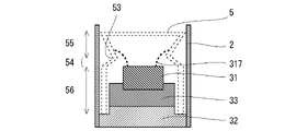
- FIG. 7 is a schematic cross-sectional view around an igniter assembly according to a second modification.
- FIG. 8 is a schematic cross-sectional view around an igniter assembly according to a third modification.
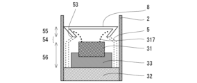
- FIG. 9 is a schematic cross-sectional view around an igniter assembly according to a fourth modification.
- FIG. 10 is a schematic cross-sectional view around an igniter assembly according to a fifth modification.
- FIG. 1 is a schematic axial sectional view showing an example of a gas generator.
- FIG. 2 is a schematic cross-sectional view for explaining the configuration of the igniter assembly and its surroundings.
- the gas generator 1 is a cylindrical device that burns a gas generating agent contained therein and discharges combustion gas to the outside, and can be used, for example, to inflate an airbag.
- the gas generator 1 of FIG. 1 includes a cylindrical housing 2, an igniter assembly 3 attached to one axial end of the housing 2, and a diffuser portion 4 formed on the other end of the housing 2. .
- the igniter assembly 3 is a device that is ignited by an ignition current and is used in existing gas generators.
- the igniter assembly 3 includes an igniter body 31 that ignites by receiving an electric current supplied from the outside, a metal collar portion 32, and a resin holding portion that fixes the igniter body 31 to the collar portion 32. 33.
- the collar portion 32 is a tubular metal member. Further, the collar portion 32 is attached to an opening portion on one axial end side of the housing 2 by, for example, all-around welding. Further, the collar portion 32 holds the igniter main body 31 via the holding portion 33 inside thereof.
- the holding portion 33 is interposed between the igniter body 31 and the collar portion 32 by injection molding, and fixes the igniter body 31 to the collar portion 32 .
- the inner peripheral surface of the collar portion 32 that contacts the holding portion 33 may be provided with unevenness.
- the igniter body 31 includes a pair of conductive pins 311, a bottomed cylindrical cup (igniter cup) 312 with one end open, a sealing member 313 that closes the opening of the cup 312, and the cup 312. and an ignition charge 314 housed in an ignition chamber 315 which is a space formed by the sealing member 313 .
- a pair of conductive pins 311 are connected within the ignition chamber 315 via a bridge wire (not shown). When the conductive pin 311 receives an electric current from the outside, the bridge wire, which is a resistor, generates heat to burn the ignition charge 314 .
- the ignition charge 314 is used in existing gas generators.
- the cup body 312 is, for example, a metal member overlaid with an insulating layer made of resin.
- the sealing member 313 is also made of metal, for example, and is insulated from one of the conductive pins 311 .
- the cup body 312 has radial notches on the surface on the side of the housing 2 (referred to as "upper surface” for convenience).
- FIG. 3 is a schematic diagram of the upper surface of the cup body 312 viewed in the axial direction of the housing 2 from the housing 2 side.
- the upper surface of the cup body 312 is formed with two cross-shaped notches 316 that intersect substantially at the center of the upper surface.
- the notch 316 guides the position where the cup body 312 breaks when the igniter body 31 is actuated.
- a deployment portion (in other words, a “scheduled deployment portion” before activation) 317 whose peripheral edge is partially defined by the notch 316 is housed in the housing 2 for generating gas. Deploy to the agent 6 side.
- three or more notches 316 may be formed so as to intersect at one point, or even if one deployment planned portion provided on the upper surface of the cup body 312 is opened in a single-sided manner. good.
- the housing 2 is, for example, a cylindrical member having substantially uniform inner and outer diameters, and forms an outer shell container of the gas generator 1 .
- the material of the housing 2 is metal, for example.
- a combustion chamber 21 is formed inside the housing 2 between the igniter assembly 3 and the diffuser portion 4 .
- the combustion chamber 21 accommodates an elastic member 5 such as a coil spring having one end adjacent to the igniter assembly 3 and a gas generating agent 6 accommodated at the other end of the elastic member 5 .
- the elastic member 5 has a tubular outer shape and is arranged in the same axial direction as the housing 2 .
- the elastic member 5 is, for example, a compression coil spring.
- One end portion 51 of the elastic member 5 is formed of a circular wire (not shown) and is fitted to the side circumference of the igniter assembly 3 . 1 and 2, the one end portion 51 of the elastic member 5 is fitted to the side circumference of the collar portion 32. may be placed on either side. Alternatively, the elastic member 5 may be fixed by welding or the like without being fitted to the side circumference of the igniter assembly 3 .
- the other end 52 of the elastic member 5 may have a spiral shape when viewed axially of the elastic member 5 .
- the spiral-shaped other end portion 52 may be sized such that the space between the wires does not allow the gas generating agent 6 to pass therethrough.
- the distance between wires adjacent to each other in the radial direction is set to a size smaller than the diameter or length of the gas generating agent, such as about 1 mm to 2 mm. In this way, the gas generating agent 6 can be urged toward the diffuser portion 4 by the elastic member 5 .
- since the movement of the gas generating agent 6 is restricted inside the gas generator 1, it is possible to prevent the gas generating agent 6 from being shaken to generate abnormal noise and to be crushed.
- a perforated member such as a punching metal, a plain-woven wire mesh, a tatami-woven wire mesh, or the like may be arranged at the end of a coil spring or the like.
- the gas generating agent 6 can be retained in the housing 2 by making the through portion of a size that makes it difficult for the gas generating agent 6 to pass through. Also in this case, for example, the diameter or one side of the opening is set to a size of about 1 mm to 2 mm.
- the elastic member 5 has a reduced-diameter portion 53 having the smallest diameter inside in the axial direction.
- the elastic member 5 has a diameter-reduced region 54 whose diameter gradually decreases from the one end portion 51 toward the diameter-reduced portion 53, and a diameter which gradually increases from the diameter-reduced portion 53 toward the other end portion 52. and an enlarged diameter region 55 .
- the gas generating agent 6 burns to generate combustion gas.
- the gas generant 6 comprises known compositions, for example formed by guanidine nitrate (41% by weight), basic copper nitrate (49% by weight) and binders and additives.
- guanidine nitrate 41% by weight
- basic copper nitrate 49% by weight
- binders and additives As for the individual shape of the gas generating agent 6, for example, a pellet shape, a disc shape, a column shape, or a single-hole cylinder shape having a through hole can be used.
- the gas generating agent 6 is not limited to the above.
- the diffuser part 4 is a tubular part formed integrally with the housing 2 and closing the other end side of the housing 2 .
- the diffuser portion 4 has a cylindrical shape with a bottom, and includes a side peripheral surface 41 and a closed end 42 opposite to the combustion chamber 21 .
- a partition wall 7 is arranged between the combustion chamber 21 and the diffuser portion 4 .
- the partition wall 7 is fixed between two plastically worked portions 43 whose diameter is reduced by caulking the housing 2, for example.
- the side peripheral surface 41 has a gas discharge hole 44 .
- the gas discharge holes 44 are through holes, and are provided in plurality along the circumferential direction of the side peripheral surface 41 .
- a plurality of gas discharge holes 44 may be provided in the axial direction of the diffuser portion 4 . Further, the gas discharge hole 44 is closed by a closing member (not shown) such as a sealing tape. The closing member is cleaved when the internal pressure of the gas generator 1 rises due to combustion gas.
- a cylindrical filter 45 is accommodated inside the side peripheral surface 41 , and the combustion gas discharged from the gas discharge holes 44 passes through the filter 45 .
- the filter 45 is held between the plastically worked portion 43 and the closed end 42 with the end on the combustion chamber 21 side abutting against the plastically worked portion 43 .
- the filter 45 may be, for example, formed by flat-knitting a metal wire material, putting it in a molding die, compression-molding it into a cylindrical shape, and providing a through hole in the axial direction.
- the filter 45 may be formed by winding a metal wire around a rod-shaped core material in a plurality of layers, and by crossing the wires to form a columnar shape having a mesh.
- the filter 45 is formed by rolling up a sheet-like perforated plate such as expanded metal, punching metal, metal lath, plain-woven wire mesh, tatami-woven wire mesh, etc. into a cylindrical shape, and providing through holes in the axial direction.
- a sheet-like perforated plate such as expanded metal, punching metal, metal lath, plain-woven wire mesh, tatami-woven wire mesh, etc.
- the filter 45 functions as a cooling unit for cooling the combustion gas, and also collects the combustion residue of the combustion gas to prevent combustion. Filter the gas.
- the partition wall 7 is, for example, a disk-shaped member, and closes the space between the diffuser portion 4 and the combustion chamber 21 .
- the partition wall 7 is arranged in the housing 2 and defines a boundary between the combustion chamber 21 containing the gas generating agent 6 and the diffuser portion 4 . Further, the partition wall 7 may be cleaved when the internal pressure of the combustion chamber is increased by the combustion gas, or may have a through hole through which the combustion gas passes.
- a connector (not shown) is connected to a pair of conductive pins 311 so that power can be supplied to the igniter assembly 3 when the gas generator 1 is assembled to, for example, an airbag of an automobile. .
- the igniter assembly 3 is activated by the ignition current supplied to the conductive pin 311 .
- the igniter assembly 3 burns the ignition charge 314 in the cup body 312 and releases the combustion products to the outside of the cup body 312 .
- the gas generating agent 6 in the combustion chamber 21 is ignited by the flame and combustion gas, which are combustion products of the ignition charge 314 .
- the gas generating agent 6 is combusted to generate combustion gas and the like as combustion products. Further, when the internal pressure of the combustion chamber 21 increases, the partition wall 7 is cleaved, and the combustion gas passes through the filter 45 of the diffuser portion 4 and is discharged from the gas discharge hole 44 .
- the exhausted combustion gas inflates, for example, an airbag (not shown).
- FIG. 4 is a cross-sectional view of the igniter assembly and its surroundings showing an example of a state in which the igniter body is activated.
- the upper surface of the cup body 312 is broken along the notch 316, and the expanded portion 317 opens toward the gas generating agent 6 side.
- the vicinity of the distal end of the expanded portion 317 abuts against the diameter-reduced portion 53 of the elastic member 5, and the angle at which the expanded portion 317 expands is restricted.
- the diameter-reduced portion 53 is located in the vicinity of the intersection of the notches 316 in the portion to be deployed (deployed portion 317) before the operation of the igniter main body 31 (that is, when the deployable portion 317 is deployed, the diameter-reduced portion 53 is located closest to the side of the gas generating agent 6). ) and the igniter main body 31 during operation, and functions as a restricting portion that restricts the deployment of the deploying portion 317 when the igniter main body 31 is activated. It should be noted that it is possible to restrict the deployment of the deployment portion 317 by bringing a part of the deployment portion 317 into contact with the reduced-diameter portion 53 , not just near the distal end of the deployment portion 317 . In this case, an intermediate portion of the expanded portion 317 that reaches the distal end portion contacts the diameter-reduced portion 53 , and the distal portion thereof contacts the expanded diameter region 55 .
- the direction in which the igniter body 31 emits combustion products is limited by the angle of the deployment portion 317, as indicated by the dashed arrow in FIG. 4, for example. That is, the combustion products of the igniter main body 31 are suppressed from diffusing in the direction of the inner wall of the housing 2 by the diameter-reduced portion 53 , and the amount guided toward the gas generating agent 6 held in the housing 2 is reduced. increase. In general, when the combustion products of the gas generant 6 are dispersed over a wide angle, some of the combustion products contact the housing 2 and are cooled.
- the combustion products of the igniter main body 31 are suppressed from dispersing and more are guided toward the gas generating agent 6, so that the ignition performance of the gas generating agent 6 is improved.
- the igniter main body 31 and the combustion chamber 21 are communicated with each other before operation, and there is nothing to hinder the deployment of the deployment portion 317 .
- the combustion products from the igniter main body 31 can ignite the gas generating agent 6 evenly and efficiently.
- the diameter-reduced region 54 can also converge the moving direction of the combustion products from the igniter and supply them to the gas generating agent 6, thereby increasing the flow velocity of the combustion products and increasing the ignitability of the gas generating agent 6. can be improved.
- the combustion products can be released so as to diffuse to the entire end portion of the gas generating agent 6 on the igniter assembly 3 side.
- coil springs are used as the elastic member 5, if a plurality of coil springs are connected in the axial direction, the ends of the coil springs contact each other or the abutting portions are deviated and the coil springs are tilted, and the combustion products are discharged into the combustion chamber 21. It may be difficult to convey to the other side. By using one coil spring, combustion products can be circulated as designed.
- FIG. 5 is a diagram for explaining the length from the igniter main body to the reduced diameter portion. Assuming that the diameter of the top surface of the cup body 312 is D, as indicated by the arrow in FIG. can do.
- the length L is the length from the upper surface of the cup body 312 to the reduced diameter portion 53 when the elastic member 5 is axially compressed before the gas generator 1 is activated. D/2 ⁇ L ⁇ D (1)
- the distal end of the expanded portion 317 moves toward the diffuser portion 4 with the peripheral edge of the cup body 312 as a rotation axis. is developed by drawing an arc with a radius of about D/2.
- the reduced diameter portion 53 at a position about D/2 from the cup body 312 .
- the tip of the developed part 317 is a diffuser with the above part of the peripheral edge of the cup body 312 as a rotation axis. It develops in the direction of the portion 4 by drawing an arc of about the diameter (D) of the cup body 312 . Therefore, it is preferable to provide the reduced diameter portion 53 at a position about D from the cup body 312 .
- the length L from the upper surface of the cup body 312 to the diameter-reduced portion approximately equal to or more than the radius of the cup body 312 and equal to or less than the diameter of the cup body 312 from the cup body 312 .
- the elastic member 5 may be formed so that the elastic modulus is lower in the expanded diameter region 55 than in the reduced diameter region 54 .
- the modulus of elasticity can be varied, for example, by varying the thickness and the number of turns of the coil spring. In this way, when the gas generator 1 is filled with the gas generating agent 6, even if there is some variation in the amount of the gas generating agent 6, the diameter-enlarged region 55 is preferentially deformed and the diameter-reduced region 54 is deformed preferentially.
- the length becomes almost constant. That is, the length from the igniter main body 31 to the reduced diameter portion 53 is substantially constant, and the tip of the cleaved cup body 312 and the reduced diameter portion 53 of the elastic member 5 are in contact with each other in a previously designed positional relationship. Become.
- FIG. 6 is a schematic cross-sectional view around an igniter assembly according to a first modification.
- the same reference numerals are given to the members corresponding to those of the above-described embodiment, and mainly the differences will be explained.
- a thin dashed line indicates the outline of the cross-sectional shape of the elastic member 5 .
- a thick dashed line schematically shows the cross-sectional shape of the developed portion 317 when cleaved.
- the elastic member 5 is arranged on the side of the holding portion 33 . Note that the elastic member 5 may be fitted with the holding portion 33 .
- the elastic member 5 has an equal diameter region 56 with a constant diameter on the igniter assembly 3 side.
- the elastic member 5 has a reduced diameter portion 53 at a position in contact with the portion to be deployed (deployed portion 317) when the igniter main body 31 is actuated, and gradually expands toward the reduced diameter portion 53 from near the upper surface of the cup body 312. It has a diameter-reduced region 54 with a smaller diameter and an enlarged-diameter region 55 with a diameter that gradually increases from the diameter-reduced portion 53 toward the diffuser portion 4 side.
- FIG. 7 is a schematic cross-sectional view around an igniter assembly according to a second modification.
- a portion of the side surface of the collar portion 32 includes a portion that is flush with the side surface of the holding portion 33 .
- the elastic member 5 is arranged on the side of the collar portion 32 and the holding portion 33 .
- the elastic member 5 may be fitted with the collar portion 32 and the holding portion 33 .
- the elastic member 5 has an equal diameter region 56 with a constant diameter on the igniter assembly 3 side.
- the elastic member 5 has a diameter-reduced portion 53 at a position in contact with the portion to be deployed (deployment portion 317) when the igniter main body 31 is actuated, and gradually expands toward the diameter-reduced portion 53 from near the upper surface of the cup body 312. It has a diameter-reduced region 54 with a smaller diameter and an enlarged-diameter region 55 with a diameter that gradually increases from the diameter-reduced portion 53 toward the diffuser portion 4 side.
- FIG. 8 is a schematic cross-sectional view around an igniter assembly according to a third modification.
- the elastic member 5 is arranged on the side of the cup body 312 .
- the elastic member 5 may be fitted with the cup body 312 .
- the elastic member 5 has an equal diameter region 56 with a constant diameter on the igniter assembly 3 side. Also, the elastic member 5 does not have the reduced diameter region 54 .
- the elastic member 5 has an enlarged diameter region 55 whose diameter gradually increases toward the side of the gas generating agent 6 at the end portion of the uniform diameter region 56 on the diffuser portion 4 side.
- the portion to be deployed (deployed portion 317 ) near the tip is in contact with the enlarged diameter region 55 .
- FIG. 9 is a schematic cross-sectional view around an igniter assembly according to a fourth modification.
- the elastic member 5 is arranged on the side of the holding portion 33 .
- the elastic member 5 may be fitted with the holding portion 33 .
- the elastic member 5 has an equal diameter region 56 with a constant diameter on the igniter assembly 3 side.
- the elastic member 5 has a diameter-reduced portion 53 at a position in contact with the portion to be deployed (deployment portion 317) when the igniter body 31 is actuated, and a diameter-reduced region in which the diameter gradually decreases from the vicinity of the upper surface of the cup body 312. 54.
- the enlarged diameter region 55 is also a coil spring, and the porous member 8 is arranged on the tip end surface (the other end portion 52).
- the porous member 8 may be a member having no elasticity, and is formed of, for example, punching metal or wire mesh.
- FIG. 10 is a schematic cross-sectional view around an igniter assembly according to a fifth modification.
- the elastic member 5 is arranged on the side of the igniter main body 31 .
- the elastic member 5 is integrally formed of, for example, three or more leaf springs 57 in the circumferential direction and an annular member 58 arranged along the inner periphery of the housing 2 and connected to the leaf springs 57. including.
- a porous member 9 such as a wire mesh is connected to the diffuser portion 4 side of the annular member 58 .
- the porous member 9 has a circular shape in a cross-sectional view (not shown) of the housing 2, and has a degree of roughness that does not allow the gas generating agent 6 to pass through.
- the portion to be deployed may be in contact with the annular member 58 when the igniter main body 31 is activated.
- the restricting portion does not have to be a portion of the elastic member 5 having the smallest diameter as long as it is a portion that abuts on the cleaved cup body 312 .
- the elastic member 5 may have a constant diameter over the entire length in the axial direction as long as it includes a restricting portion that restricts the direction in which the cleaved cup body 312 expands.
- the igniter main body 31 has an igniter on the sealing member 313 (on the side of the combustion chamber 21), and the igniter from the side (outside in the radial direction of the housing 2).
- a surrounding metal charge holder may be provided.
- one elastic member 5 is preferably arranged between the igniter assembly 3 and the combustion chamber 21 . Further, when the other end portion 52 of the elastic member 5 has a spiral shape, a penetrating portion (that is, a gap) is formed between adjacent wire rods in the radial direction. At this time, the space formed inside the elastic member 5 in which the igniter main body 31 is arranged and the space in which the gas generating agent 6 is arranged in the combustion chamber 21 are the same even in the state before the gas generator 1 operates. It is preferable that they communicate with each other through a through portion. That is, since the igniter main body 31 and the gas generating agent 6 are in communication before the gas generator 1 operates, combustion products from the ignition agent 314 easily reach the gas generating agent 6 . Therefore, the ignition performance and combustion performance of the gas generating agent 6 are improved.
- the other spiral end portion 52 may have a shape in which the radial center portion protrudes toward the combustion chamber 21 side or toward the igniter main body 31 side.
- the cross-sectional shape may be an annular slanted surface or a curved slanted surface from the projecting central portion to the peripheral edge of the other end portion 52 .
- the radial center portion of the other end portion 52 of the elastic member 5 may be protruded toward the igniter main body 31 side, and the transfer charge may be disposed in a recess recessed toward the combustion chamber 21 side.
- the portion protruding toward the combustion chamber 21 side or the igniter body 31 side is not limited to the radial center portion, and a plurality of portions may protrude.
- the partially projecting other end portion 52 does not have to be spiral, and is formed of a porous member such as expanded metal, punching metal, metal lath, plain-woven wire mesh, tatami-woven wire mesh, etc., and is combined with a coil spring. may be used.
- the distance between axially adjacent wire rods in the enlarged diameter region 55 may be shorter than the distance between axially adjacent wire rods in the reduced diameter region 54 . That is, the wire rod spacing in the diameter-increased region 55 is made closer than that in the diameter-reduced region 54 facing the cup body 312 (deployed portion 317) that is cleaved when the igniter body 31 is actuated, and combustion products are generated around the elastic member 5. can be suppressed from being discharged.
- Gas generator 2 Housing 21: Combustion chamber 3: Ignitor assembly 31: Ignitor body 311: Conductive pin 312: Cup body 313: Sealing member 314: Ignition powder 315: Ignition chamber 316: Notch 317: Deployment Part 32: Collar part 33: Holding part 4: Diffuser part 41: Side peripheral surface 42: Closed end 43: Plastic processing part 44: Gas discharge hole 45: Filter 5: Elastic member 51: One end 52: Other end 53: Diameter reduction portion 54: Diameter reduction region 55: Diameter expansion region 56: Equal diameter region 57: Leaf spring 58: Annular member 6: Gas generating agent 7: Partition wall 8: Porous member 9: Porous member 9: Porous member
Landscapes
- Engineering & Computer Science (AREA)
- Mechanical Engineering (AREA)
- Physics & Mathematics (AREA)
- Fluid Mechanics (AREA)
- General Engineering & Computer Science (AREA)
- Air Bags (AREA)
Priority Applications (4)
| Application Number | Priority Date | Filing Date | Title |
|---|---|---|---|
| EP22872671.7A EP4406788A4 (en) | 2021-09-22 | 2022-09-01 | GAS GENERATOR |
| CN202280063446.1A CN117980194A (zh) | 2021-09-22 | 2022-09-01 | 气体发生器 |
| JP2023549445A JP7781168B2 (ja) | 2021-09-22 | 2022-09-01 | ガス発生器 |
| US18/608,009 US12496996B2 (en) | 2021-09-22 | 2024-03-18 | Gas generator |
Applications Claiming Priority (2)
| Application Number | Priority Date | Filing Date | Title |
|---|---|---|---|
| JP2021154424 | 2021-09-22 | ||
| JP2021-154424 | 2021-09-22 |
Related Child Applications (1)
| Application Number | Title | Priority Date | Filing Date |
|---|---|---|---|
| US18/608,009 Continuation US12496996B2 (en) | 2021-09-22 | 2024-03-18 | Gas generator |
Publications (1)
| Publication Number | Publication Date |
|---|---|
| WO2023047915A1 true WO2023047915A1 (ja) | 2023-03-30 |
Family
ID=85720547
Family Applications (1)
| Application Number | Title | Priority Date | Filing Date |
|---|---|---|---|
| PCT/JP2022/033023 Ceased WO2023047915A1 (ja) | 2021-09-22 | 2022-09-01 | ガス発生器 |
Country Status (5)
| Country | Link |
|---|---|
| US (1) | US12496996B2 (https=) |
| EP (1) | EP4406788A4 (https=) |
| JP (1) | JP7781168B2 (https=) |
| CN (1) | CN117980194A (https=) |
| WO (1) | WO2023047915A1 (https=) |
Cited By (2)
| Publication number | Priority date | Publication date | Assignee | Title |
|---|---|---|---|---|
| DE102022124029A1 (de) | 2022-09-20 | 2024-03-21 | Zf Airbag Germany Gmbh | Gasgenerator |
| US20250136034A1 (en) * | 2021-03-19 | 2025-05-01 | Nippon Kayaku Kabushiki Kaisha | Gas generator |
Families Citing this family (2)
| Publication number | Priority date | Publication date | Assignee | Title |
|---|---|---|---|---|
| DE112023002560T5 (de) * | 2022-06-06 | 2025-04-17 | Daicel Corporation | Gasgenerator |
| JP7765363B2 (ja) * | 2022-08-26 | 2025-11-06 | 日本化薬株式会社 | ガス発生器 |
Citations (5)
| Publication number | Priority date | Publication date | Assignee | Title |
|---|---|---|---|---|
| JP2002079903A (ja) | 2000-06-22 | 2002-03-19 | Daicel Chem Ind Ltd | エアバッグ用ガス発生器 |
| US20160167618A1 (en) * | 2014-12-10 | 2016-06-16 | Michael P. Jordan | Initiator assemblies |
| JP2017007456A (ja) | 2015-06-19 | 2017-01-12 | 日本化薬株式会社 | ガス発生器 |
| US20190047508A1 (en) * | 2015-10-02 | 2019-02-14 | Trw Airbag Systems Gmbh | Gas generator, in particular for a vehicle occupant protection system, spring for arranging in a gas generator, airbag module, and vehicle occupant protection system |
| JP2019214359A (ja) * | 2018-05-18 | 2019-12-19 | ティーアールダブリュー・エアバッグ・システムズ・ゲーエムベーハー | 管状インフレータのための推進剤ケージ、管状インフレータのためのパッキン要素、エアバッグモジュールのための管状インフレータ、エアバッグモジュール、自動車安全システム、管状インフレータの動作および製造方法 |
Family Cites Families (4)
| Publication number | Priority date | Publication date | Assignee | Title |
|---|---|---|---|---|
| DE112017002069B4 (de) * | 2016-04-18 | 2023-05-25 | Nippon Kayaku Kabushiki Kaisha | Gasgenerator mit Selbstentzündungsmittel |
| JP7436297B2 (ja) * | 2020-06-15 | 2024-02-21 | 日本化薬株式会社 | ガス発生器 |
| WO2022196228A1 (ja) * | 2021-03-19 | 2022-09-22 | 日本化薬株式会社 | ガス発生器 |
| US12403860B2 (en) * | 2021-12-14 | 2025-09-02 | Nippon Kayaku Kabushiki Kaisha | Gas generator |
-
2022
- 2022-09-01 EP EP22872671.7A patent/EP4406788A4/en active Pending
- 2022-09-01 JP JP2023549445A patent/JP7781168B2/ja active Active
- 2022-09-01 CN CN202280063446.1A patent/CN117980194A/zh active Pending
- 2022-09-01 WO PCT/JP2022/033023 patent/WO2023047915A1/ja not_active Ceased
-
2024
- 2024-03-18 US US18/608,009 patent/US12496996B2/en active Active
Patent Citations (5)
| Publication number | Priority date | Publication date | Assignee | Title |
|---|---|---|---|---|
| JP2002079903A (ja) | 2000-06-22 | 2002-03-19 | Daicel Chem Ind Ltd | エアバッグ用ガス発生器 |
| US20160167618A1 (en) * | 2014-12-10 | 2016-06-16 | Michael P. Jordan | Initiator assemblies |
| JP2017007456A (ja) | 2015-06-19 | 2017-01-12 | 日本化薬株式会社 | ガス発生器 |
| US20190047508A1 (en) * | 2015-10-02 | 2019-02-14 | Trw Airbag Systems Gmbh | Gas generator, in particular for a vehicle occupant protection system, spring for arranging in a gas generator, airbag module, and vehicle occupant protection system |
| JP2019214359A (ja) * | 2018-05-18 | 2019-12-19 | ティーアールダブリュー・エアバッグ・システムズ・ゲーエムベーハー | 管状インフレータのための推進剤ケージ、管状インフレータのためのパッキン要素、エアバッグモジュールのための管状インフレータ、エアバッグモジュール、自動車安全システム、管状インフレータの動作および製造方法 |
Non-Patent Citations (1)
| Title |
|---|
| See also references of EP4406788A4 |
Cited By (3)
| Publication number | Priority date | Publication date | Assignee | Title |
|---|---|---|---|---|
| US20250136034A1 (en) * | 2021-03-19 | 2025-05-01 | Nippon Kayaku Kabushiki Kaisha | Gas generator |
| DE102022124029A1 (de) | 2022-09-20 | 2024-03-21 | Zf Airbag Germany Gmbh | Gasgenerator |
| US12370974B2 (en) | 2022-09-20 | 2025-07-29 | Zf Airbag Germany Gmbh | Gas generator |
Also Published As
| Publication number | Publication date |
|---|---|
| CN117980194A (zh) | 2024-05-03 |
| JPWO2023047915A1 (https=) | 2023-03-30 |
| US12496996B2 (en) | 2025-12-16 |
| JP7781168B2 (ja) | 2025-12-05 |
| US20240217474A1 (en) | 2024-07-04 |
| EP4406788A1 (en) | 2024-07-31 |
| EP4406788A4 (en) | 2025-09-03 |
Similar Documents
| Publication | Publication Date | Title |
|---|---|---|
| WO2023047915A1 (ja) | ガス発生器 | |
| JP5921232B2 (ja) | ガス発生器 | |
| JP3781603B2 (ja) | ガス発生器 | |
| JPWO2023047915A5 (https=) | ||
| US20190047508A1 (en) | Gas generator, in particular for a vehicle occupant protection system, spring for arranging in a gas generator, airbag module, and vehicle occupant protection system | |
| US20030030259A1 (en) | Gas generator | |
| US20240318943A1 (en) | Gas generator | |
| US11173868B2 (en) | Gas generator | |
| WO2022196228A1 (ja) | ガス発生器 | |
| JP2025161898A (ja) | ガス発生器 | |
| JP7636233B2 (ja) | ガス発生器 | |
| EP1927519A2 (en) | Inflator | |
| JP2015157586A (ja) | ガス発生器 | |
| US20080069740A1 (en) | Gas generator for restraining device of vehicle | |
| JP6933527B2 (ja) | ガス発生器 | |
| JP7665503B2 (ja) | ガス発生器 | |
| WO2022244294A1 (ja) | ガス発生器及びガス排出方法 | |
| JP7238302B2 (ja) | ガス発生器 | |
| JP5006205B2 (ja) | ガスマイクロジェネレータを有する自動車用安全装置 | |
| JP2022144932A (ja) | ガス発生器 | |
| JP7748396B2 (ja) | ガス発生器 | |
| JP2000329500A (ja) | スクイブ | |
| WO2002036394A1 (en) | Gas generator | |
| JP2024100623A (ja) | ガス発生器 | |
| JP2025172649A (ja) | ガス発生器 |
Legal Events
| Date | Code | Title | Description |
|---|---|---|---|
| 121 | Ep: the epo has been informed by wipo that ep was designated in this application |
Ref document number: 22872671 Country of ref document: EP Kind code of ref document: A1 |
|
| WWE | Wipo information: entry into national phase |
Ref document number: 2023549445 Country of ref document: JP |
|
| WWE | Wipo information: entry into national phase |
Ref document number: 202280063446.1 Country of ref document: CN |
|
| WWE | Wipo information: entry into national phase |
Ref document number: 202417027880 Country of ref document: IN |
|
| WWE | Wipo information: entry into national phase |
Ref document number: 2022872671 Country of ref document: EP |
|
| NENP | Non-entry into the national phase |
Ref country code: DE |
|
| ENP | Entry into the national phase |
Ref document number: 2022872671 Country of ref document: EP Effective date: 20240422 |