WO2023047847A1 - 液体供給装置 - Google Patents
液体供給装置 Download PDFInfo
- Publication number
- WO2023047847A1 WO2023047847A1 PCT/JP2022/031117 JP2022031117W WO2023047847A1 WO 2023047847 A1 WO2023047847 A1 WO 2023047847A1 JP 2022031117 W JP2022031117 W JP 2022031117W WO 2023047847 A1 WO2023047847 A1 WO 2023047847A1
- Authority
- WO
- WIPO (PCT)
- Prior art keywords
- supply device
- liquid supply
- magnet
- housing
- cam member
- Prior art date
- Legal status (The legal status is an assumption and is not a legal conclusion. Google has not performed a legal analysis and makes no representation as to the accuracy of the status listed.)
- Ceased
Links
Images




Classifications
-
- F—MECHANICAL ENGINEERING; LIGHTING; HEATING; WEAPONS; BLASTING
- F04—POSITIVE - DISPLACEMENT MACHINES FOR LIQUIDS; PUMPS FOR LIQUIDS OR ELASTIC FLUIDS
- F04B—POSITIVE-DISPLACEMENT MACHINES FOR LIQUIDS; PUMPS
- F04B1/00—Multi-cylinder machines or pumps characterised by number or arrangement of cylinders
- F04B1/12—Multi-cylinder machines or pumps characterised by number or arrangement of cylinders having cylinder axes coaxial with, or parallel or inclined to, main shaft axis
- F04B1/14—Multi-cylinder machines or pumps characterised by number or arrangement of cylinders having cylinder axes coaxial with, or parallel or inclined to, main shaft axis having stationary cylinders
- F04B1/141—Details or component parts
- F04B1/146—Swash plates; Actuating elements
-
- F—MECHANICAL ENGINEERING; LIGHTING; HEATING; WEAPONS; BLASTING
- F04—POSITIVE - DISPLACEMENT MACHINES FOR LIQUIDS; PUMPS FOR LIQUIDS OR ELASTIC FLUIDS
- F04B—POSITIVE-DISPLACEMENT MACHINES FOR LIQUIDS; PUMPS
- F04B1/00—Multi-cylinder machines or pumps characterised by number or arrangement of cylinders
- F04B1/12—Multi-cylinder machines or pumps characterised by number or arrangement of cylinders having cylinder axes coaxial with, or parallel or inclined to, main shaft axis
- F04B1/122—Details or component parts, e.g. valves, sealings or lubrication means
-
- F—MECHANICAL ENGINEERING; LIGHTING; HEATING; WEAPONS; BLASTING
- F04—POSITIVE - DISPLACEMENT MACHINES FOR LIQUIDS; PUMPS FOR LIQUIDS OR ELASTIC FLUIDS
- F04B—POSITIVE-DISPLACEMENT MACHINES FOR LIQUIDS; PUMPS
- F04B1/00—Multi-cylinder machines or pumps characterised by number or arrangement of cylinders
- F04B1/12—Multi-cylinder machines or pumps characterised by number or arrangement of cylinders having cylinder axes coaxial with, or parallel or inclined to, main shaft axis
- F04B1/14—Multi-cylinder machines or pumps characterised by number or arrangement of cylinders having cylinder axes coaxial with, or parallel or inclined to, main shaft axis having stationary cylinders
- F04B1/16—Multi-cylinder machines or pumps characterised by number or arrangement of cylinders having cylinder axes coaxial with, or parallel or inclined to, main shaft axis having stationary cylinders having two or more sets of cylinders or pistons
-
- F—MECHANICAL ENGINEERING; LIGHTING; HEATING; WEAPONS; BLASTING
- F04—POSITIVE - DISPLACEMENT MACHINES FOR LIQUIDS; PUMPS FOR LIQUIDS OR ELASTIC FLUIDS
- F04B—POSITIVE-DISPLACEMENT MACHINES FOR LIQUIDS; PUMPS
- F04B23/00—Pumping installations or systems
- F04B23/04—Combinations of two or more pumps
- F04B23/06—Combinations of two or more pumps the pumps being all of reciprocating positive-displacement type
-
- F—MECHANICAL ENGINEERING; LIGHTING; HEATING; WEAPONS; BLASTING
- F04—POSITIVE - DISPLACEMENT MACHINES FOR LIQUIDS; PUMPS FOR LIQUIDS OR ELASTIC FLUIDS
- F04B—POSITIVE-DISPLACEMENT MACHINES FOR LIQUIDS; PUMPS
- F04B43/00—Machines, pumps, or pumping installations having flexible working members
- F04B43/0009—Special features
- F04B43/0045—Special features with a number of independent working chambers which are actuated successively by one mechanism
-
- F—MECHANICAL ENGINEERING; LIGHTING; HEATING; WEAPONS; BLASTING
- F04—POSITIVE - DISPLACEMENT MACHINES FOR LIQUIDS; PUMPS FOR LIQUIDS OR ELASTIC FLUIDS
- F04B—POSITIVE-DISPLACEMENT MACHINES FOR LIQUIDS; PUMPS
- F04B43/00—Machines, pumps, or pumping installations having flexible working members
- F04B43/0009—Special features
- F04B43/0054—Special features particularities of the flexible members
-
- F—MECHANICAL ENGINEERING; LIGHTING; HEATING; WEAPONS; BLASTING
- F04—POSITIVE - DISPLACEMENT MACHINES FOR LIQUIDS; PUMPS FOR LIQUIDS OR ELASTIC FLUIDS
- F04B—POSITIVE-DISPLACEMENT MACHINES FOR LIQUIDS; PUMPS
- F04B53/00—Component parts, details or accessories not provided for in, or of interest apart from, groups F04B1/00 - F04B23/00 or F04B39/00 - F04B47/00
-
- F—MECHANICAL ENGINEERING; LIGHTING; HEATING; WEAPONS; BLASTING
- F04—POSITIVE - DISPLACEMENT MACHINES FOR LIQUIDS; PUMPS FOR LIQUIDS OR ELASTIC FLUIDS
- F04B—POSITIVE-DISPLACEMENT MACHINES FOR LIQUIDS; PUMPS
- F04B9/00—Piston machines or pumps characterised by the driving or driven means to or from their working members
- F04B9/02—Piston machines or pumps characterised by the driving or driven means to or from their working members the means being mechanical
-
- F—MECHANICAL ENGINEERING; LIGHTING; HEATING; WEAPONS; BLASTING
- F04—POSITIVE - DISPLACEMENT MACHINES FOR LIQUIDS; PUMPS FOR LIQUIDS OR ELASTIC FLUIDS
- F04B—POSITIVE-DISPLACEMENT MACHINES FOR LIQUIDS; PUMPS
- F04B9/00—Piston machines or pumps characterised by the driving or driven means to or from their working members
- F04B9/02—Piston machines or pumps characterised by the driving or driven means to or from their working members the means being mechanical
- F04B9/04—Piston machines or pumps characterised by the driving or driven means to or from their working members the means being mechanical the means being cams, eccentrics or pin-and-slot mechanisms
-
- F—MECHANICAL ENGINEERING; LIGHTING; HEATING; WEAPONS; BLASTING
- F04—POSITIVE - DISPLACEMENT MACHINES FOR LIQUIDS; PUMPS FOR LIQUIDS OR ELASTIC FLUIDS
- F04B—POSITIVE-DISPLACEMENT MACHINES FOR LIQUIDS; PUMPS
- F04B9/00—Piston machines or pumps characterised by the driving or driven means to or from their working members
- F04B9/02—Piston machines or pumps characterised by the driving or driven means to or from their working members the means being mechanical
- F04B9/04—Piston machines or pumps characterised by the driving or driven means to or from their working members the means being mechanical the means being cams, eccentrics or pin-and-slot mechanisms
- F04B9/042—Piston machines or pumps characterised by the driving or driven means to or from their working members the means being mechanical the means being cams, eccentrics or pin-and-slot mechanisms the means being cams
-
- G—PHYSICS
- G01—MEASURING; TESTING
- G01D—MEASURING NOT SPECIALLY ADAPTED FOR A SPECIFIC VARIABLE; ARRANGEMENTS FOR MEASURING TWO OR MORE VARIABLES NOT COVERED IN A SINGLE OTHER SUBCLASS; TARIFF METERING APPARATUS; MEASURING OR TESTING NOT OTHERWISE PROVIDED FOR
- G01D5/00—Mechanical means for transferring the output of a sensing member; Means for converting the output of a sensing member to another variable where the form or nature of the sensing member does not constrain the means for converting; Transducers not specially adapted for a specific variable
- G01D5/12—Mechanical means for transferring the output of a sensing member; Means for converting the output of a sensing member to another variable where the form or nature of the sensing member does not constrain the means for converting; Transducers not specially adapted for a specific variable using electric or magnetic means
-
- F—MECHANICAL ENGINEERING; LIGHTING; HEATING; WEAPONS; BLASTING
- F05—INDEXING SCHEMES RELATING TO ENGINES OR PUMPS IN VARIOUS SUBCLASSES OF CLASSES F01-F04
- F05C—INDEXING SCHEME RELATING TO MATERIALS, MATERIAL PROPERTIES OR MATERIAL CHARACTERISTICS FOR MACHINES, ENGINES OR PUMPS OTHER THAN NON-POSITIVE-DISPLACEMENT MACHINES OR ENGINES
- F05C2251/00—Material properties
- F05C2251/12—Magnetic properties
Definitions
- the present invention relates to a liquid supply device that continuously discharges liquid by driving a plurality of pump members.
- a liquid supply device is used to apply a liquid such as a photoresist liquid to the surface of a liquid crystal display substrate.
- a liquid supply device is classified into a piston type, a bellows type, a tube frame type, and the like, depending on the members incorporated therein.
- the piston type has a piston that reciprocates in a cylinder chamber, and the piston expands and contracts a pump chamber that is partitioned from the cylinder chamber by the piston.
- the bellows type has a bellows that is accommodated in a pump block and expands and contracts, and the bellows expands and contracts a pump chamber partitioned by the pump block and the bellows.
- the tubeflam type has a tubeflam with a pump chamber formed inside, and expands and contracts the pump chamber by supplying and discharging an indirect medium to and from the outside drive chamber.
- Patent Document 1 describes a piston type and a tubeflam type liquid supply device.
- the liquid supply device has a plurality of pump chambers in order to continuously discharge the liquid.
- a plurality of rods for expanding and contracting the respective pump chambers are driven by one electric motor through cam members.
- a constant amount of liquid can be continuously discharged by shifting the discharge timing of each pump by the cam member.
- an encoder that monitors the rotation of the output shaft of the electric motor By attaching an encoder that monitors the rotation of the output shaft of the electric motor to the casing of the electric motor, it is possible to detect pump failure. If the failure of the device is detected by detecting the rotation of the output shaft with an encoder, even if the electric motor rotates at a predetermined number of revolutions, if the cam member does not rotate at the set number of revolutions, , fault detection is not possible. Moreover, there is a problem that the encoder becomes expensive if a signal processing circuit from the encoder is included.
- An object of the present invention is to provide a liquid supply device that can detect whether or not the cam member is reliably rotating with a simple mechanism.
- the liquid supply device includes a pump unit provided with a plurality of pump members for expanding and contracting pump chambers, a housing incorporating a plurality of drive rods for driving the plurality of pump members at different timings, and A drive roller that rotates around a rotation center axis that is transverse to the reciprocating direction of the drive rod, and a cam surface with which the drive roller contacts are provided on the end face, and the drive rod is rotated by a rotational drive source.
- a cam member that is rotationally driven about a central axis of rotation parallel to the reciprocating direction, a magnet that is provided on the outer periphery of the cam member, and a rotation signal that is provided in the housing and responds to the magnetic force of the magnet. and a magnetic sensor that outputs.
- the magnetic force of the magnet provided on the outer circumference of the cam member is detected by the magnetic sensor provided in the housing, and the rotation of the cam member is detected.
- a transmission failure or the like can be reliably detected by a low-cost, simple mechanism.
- FIG. 1 is a plan view of a liquid supply device that is an embodiment
- FIG. FIG. 2 is an enlarged sectional view of the front side of FIG. 1
- FIG. 2 is an enlarged sectional view of the plane side of FIG. 1
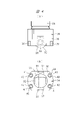
- (A) is a front view showing the guide cylinder shown in FIG. 2, and (B) is a bottom view of (A).
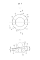
- (A) is a plan view of a cam member, and (B) is a cross-sectional view taken along the line AA in (A).
- 3 is a view showing the side surface of FIG. 2 and the piping of the liquid supply device;
- FIG. 3 is an enlarged cross-sectional view of a portion B in FIG. 2;
- the liquid supply device 10 has a pump unit 11 and a drive unit 12 , and the pump unit 11 is attached to the drive unit 12 .
- the pump unit 11 has a pump block 14 formed with two concave surfaces 13.
- the pump block 14 has rectangular side surfaces and is made of resin or metal, as shown in FIG. It is
- the drive unit 12 has a housing 15, and the housing 15 includes a connecting portion 15a to which the pump block 14 is attached, a front wall 15b, a rear wall 15c, left and right side walls 15d and 15e, and a bottom wall 15f.
- a first bellows 16 a and a second bellows 16 b made of resin as pump members are arranged in the respective concave surfaces 13 .
- the respective bellows 16a, 16b have the same structure, the members for driving them are denoted by the same reference numerals, and the head portion 17, the annular base portion 18, and the space between the head portion 17 and the annular base portion 18. It has a bellows portion 19 integrally provided with it.
- a pump chamber 20 is formed between each bellows 16a, 16b and the concave surface 13, and each pump chamber 20 expands and contracts by expansion and contraction of the bellows 16a, 16b.
- a cylindrical spring receiving tube 21 is disposed within each bellows 16a, 16b, and the flange 22 of the spring receiving tube 21 and the annular base 18 of the bellows 16a, 16b are positioned between the pump block 14 and the housing 15. is sandwiched.
- a plunger 23 is arranged inside the spring receiving cylindrical body 21 , the tip of the plunger 23 is screwed to the head portion 17 , and the base end of the plunger 23 protrudes into a through hole 24 formed in the housing 15 .
- a spring receiving member 25 is provided at the proximal end of the plunger 23 .
- the spring receiving member 25 may be integrated with the plunger 23, or the plunger 23 and the spring receiving member 25 may be separate members.
- a compression coil spring 27 is arranged outside the plunger 23 , one end of the compression coil spring 27 abuts the stepped portion of the spring receiving cylinder 21 and the other end abuts the spring receiving member 25 .
- a spring force directed downward in FIG. 3 is applied to the plunger 23 by a compression coil spring 27 .
- a spring force is applied to the bellows 16a and 16b through the plunger 23 so that the head portion 17 faces the annular base portion 18 and contracts the bellows portion 19 in the axial direction. 20 is inflated.
- the plunger 23 is pressed by the spring force of the compression coil spring 27 against the drive rods 28, which are indicated by symbol P in FIG. 3 and can reciprocate in the axial direction.
- a cover portion 29 that covers the base end portion of the plunger 23 is provided at the upper end portion of the drive rod 28 .
- a roller accommodation portion 31 is provided at the lower end of the drive rod 28 , and the drive roller 32 is arranged in the roller accommodation portion 31 .
- a support shaft 33 in a direction perpendicular to the reciprocating direction P of the drive rod 28 is provided on the drive rod 28 , and the drive roller 32 is mounted on the support shaft 33 .
- the drive roller 32 rotates about the rotation center axis R that is transverse to the reciprocating direction of the drive rod 28 in the axial direction P. As shown in FIG.
- Each rotation central axis R is coaxial.
- a guide cylinder 34 is attached to the through hole 24, and as shown in FIG. have.
- Guide rollers 37 are provided at both ends of the support shaft 33
- guide grooves 38 for guiding the guide rollers 37 are provided in the guide cylinder 34 .
- the guide groove 38 contacts the guide roller 37 and guides the vertical movement of the guide roller 37 in FIGS.
- Four slits 39 extending in the axial direction from the lower end surface of the guide portion 36 are formed in the lower end portion of the guide portion 36, and mounting holes 41 penetrating between the bottom surface of each slit 39 and the upper surface of the guide portion 36 are formed in the guide portion. 36 is formed.
- the guide cylinder 34 is fixed to the housing 15 by bolts 42 attached to the respective attachment holes 41 .
- a cam member 43 is provided on the housing 15 so as to be rotatable about a rotation center axis O parallel to the reciprocating direction P of the drive rod 28. Supported.
- An electric motor 45 as a rotational driving source is attached to the bottom wall 15f, an output shaft 46 of the electric motor 45 is attached to the cam member 43, and the cam member 43 is rotated by the electric motor 45.
- the cam member 43 is accommodated in a drive chamber 47 formed between the connecting portion 15a of the housing 15 and the bottom wall 15f.
- FIG. 5(A) is a plan view of the cam member 43
- FIG. 5(B) is a cross-sectional view taken along line AA in FIG. 5(A).
- the cam member 43 is an end-face cam in which an annular cam surface 48 is formed on the outer peripheral portion of the end face of a disk-shaped member. It has a retreating surface 50 at a position retreated from the cam member 43 by 180 degrees in the rotational direction S of the cam member 43 and an inclined surface 51 therebetween.
- the projecting surface 49 is shown on the right side of the cam member 43 and the receding surface 50 is shown on the left side of the cam member 43 .
- the projecting surface 49 is shown in the central portion of the cam member 43 without showing the entire cam member 43 as a cross section.
- the two drive rollers 32 are shifted 180 degrees from the cam member 43 in the direction of rotation of the cam member 43 , and when one drive roller 32 contacts the projecting surface 49 , the other drive roller 32 moves toward the retreating surface 50 .
- Contact For example, when the drive roller 32 attached to one of the drive rods 28 for driving the first bellows 16a contacts the projecting surface 49, the one drive rod 28 is in the raised end position in FIGS. As a result, the head portion 17 of the bellows 16a is at the raised end position, the bellows portion 19 is extended, that is, the expanded state, and the pump chamber 20 is contracted by the bellows 16a.
- the drive roller 32 attached to the other drive rod 28 for driving the second bellows 16b contacts the retreat surface 50 due to spring force.
- the other drive rod 28 is at the retracted end position
- the head portion 17 of the bellows 16b is at the retracted end position
- the bellows portion 19 is contracted.
- the pump chamber 20 is expanded by the bellows 16b.
- the rotation of the cam member 43 causes the two bellows 16a and 16b to alternately expand and contract and are driven at different timings.
- the two pump chambers 20 alternately expand and contract.
- the axial length of the portion of the cam member 43 where the projecting surface 49 is formed is L1
- the axial length of the portion where the receding surface 50 is formed is L2. Then, the portion where the projecting surface 49 is formed is the portion with the longest length in the axial direction with respect to the other portions.
- Lubricating oil is applied to the rotating members such as the driving roller 32 and the guide roller 37 in the driving chamber 47 and to the members with which the rotating members come into contact.
- a seal member 52 is mounted between the guide cylinder 34 and the drive rod 28 to prevent the lubricating oil in the drive chamber 47 from flowing out toward the plunger 23 and the pump block 14 .
- a seal member 53 is attached to the .
- suction ports 54 are formed in the bottom surface of the pump block 14 in communication with the respective pump chambers 20 , and discharge ports 55 are formed in the top surface of the pump block 14 .
- a suction side pipe 57 is connected to a liquid tank 56 into which liquid is injected, and branch portions 57 a and 57 b of the suction side pipe 57 are connected to the suction port 54 .
- a discharge side pipe 59 is connected to the discharge member 58 , and branch portions 59 a and 59 b of the discharge side pipe 59 are connected to the discharge port 55 .
- a check valve 61 is provided at each of the branch portions 57a and 57b.
- the check valve 61 operates to supply the liquid from the liquid tank 56 to the pump chamber 20 via the suction side pipe 57 and to prevent the reverse flow of the liquid.
- a check valve 62 is provided at each of the branch portions 59a and 59b to operate in a state of discharging the liquid from the pump chamber 20 to the discharge member 58 via the discharge side pipe 59 and a state of preventing the reverse flow of the liquid.
- the electric motor 45 is driven to rotate the output shaft 46.
- the cam member 43 is rotated around the rotation center axis O, and the two bellows 16a and 16b are driven at different timings via the plunger 23 by the driving roller 32 in contact with the cam surface 48. . That is, when one bellows 16 a expands and discharges liquid from one pump chamber 20 to the discharge member 58 , the other bellows 16 b contracts and liquid is injected from the liquid tank 56 into the other pump chamber 20 . At this time, the contraction motion of the bellows 16 b is performed by the spring force of the compression coil spring 27 .
- liquid is continuously discharged from the liquid supply device 10 to the discharge member 58 at a constant discharge amount.
- the position of the suction port 54 is not limited to the bottom side as long as the pump block 14 is provided.
- the position of the discharge port 55 is not limited to the upper surface side.
- the axial length of the portion of the cam surface 48 where the projecting surface 49 is formed is L1
- a thin portion 64 is a portion having an axial length of L2 where the receding surface 50 is formed at a position shifted by 180 degrees from the thick portion 63 in the rotational direction.
- FIG. 7 is an enlarged cross-sectional view of the B portion in FIG. 2
- FIG. 8 is a CC line cross-sectional view in FIG. 7
- FIG. 9 is an enlarged cross-sectional view of the D portion in FIG.
- a magnet accommodation hole 65 is formed in the outer peripheral portion of the cam member 43, and the magnet accommodation hole 65 opens to the outer peripheral surface of the cam member 43.
- the magnet accommodation hole 65 is formed in the thick portion 63 having the longest axial length in the outer peripheral portion of the cam member 43 .
- a magnet 66 is arranged in the magnet housing hole 65, and the magnet 66 is covered with a magnet holder 67 made of resin, which is a non-magnetic material.
- the magnet 66 has a cylindrical shape, and the upper and lower end faces in FIG. 7 have opposite polarities.
- the magnet 66 is brought close to the outer peripheral side of the cam member 43, and the thickness of the magnet holder 67 on the outer peripheral side of the cam member 43 is set thin.
- the magnet holder 67 is prevented from coming off by engaging the cam member 43 with a claw portion 68 formed on the outer peripheral portion, and the rotation of the magnet holder 67 is prevented by a pin 69 attached to the cam member 43 .
- the magnet 66 is provided in the portion L1 of the cam member 43 having the longest length in the axial direction, that is, the thick portion 63 .
- the thick portion 63 for forming the projecting surface 49 is used to dispose the magnet 66 there. can be incorporated.
- the magnet is not shown in the thick portion 63 where the projecting surface 49 is formed.
- a magnetic sensor 71 is provided on the front wall 15 b of the housing 15 .
- the magnetic sensor 71 is incorporated in a housing groove 72 formed in the front wall 15b corresponding to the position of the magnet 66, as shown in FIGS. Therefore, when the cam member 43 rotates, the magnetic field of the magnet 66 permeates the magnet holder 67 and is applied to the magnetic sensor 71 every rotation, and the magnetic sensor 71 responds to the magnetic force of the magnet 66 and outputs a rotation signal.
- An output signal from the magnetic sensor 71 is output to a control unit (not shown), and the control unit determines whether or not the cam member 43 is rotating. Calculated.
- the magnetic field of the magnet 66 cannot be detected by the magnetic sensor 71 if the cam member 43 is made of a magnetic material.
- a magnetic material can be used for the cam member 43 when the magnet 66 covered with the non-magnetic magnet holder 67 is arranged in the magnet housing hole 65 .
- a viewing window 73 is provided in the housing 15, as shown in FIGS.
- the observation window 73 is provided on the front wall 15b adjacent to the magnetic sensor 71 so that its vertical position in FIG. Make visible from the outside. This allows the operator to observe the rotation of the cam member 43 from the outside of the liquid supply device 10 . Visibility is improved by making one or both of the magnet holder 67 and the magnet 66 a different color from that of the cam member 43 .
- a transparent cover member 74 is attached to the observation window 73 in order to prevent foreign matter from entering the driving chamber 47 from the outside. In FIG. 8, the position of the magnet 66 at the observation window 73 is indicated by a chain double-dashed line.
- the liquid supply device 10 described above includes two bellows 16a and 16b as pump members, the number of bellows is not limited to two, and may be three or more.
- the pump member is not limited to the bellows described above, and may be a piston or a tube fram.
- the magnet housing hole 65 may be provided in a portion other than the thick portion of the cam member 43 .
- the rotary drive source is not limited to an electric motor, and an air motor can also be used. Also, a stepping motor, a servo motor, or an induction motor can be used as the electric motor.
- a liquid supply device is applied to supply a liquid to an object to be coated, for example, when coating a liquid such as a photoresist liquid on the surface of a liquid crystal display substrate.
Landscapes
- Engineering & Computer Science (AREA)
- Mechanical Engineering (AREA)
- General Engineering & Computer Science (AREA)
- Physics & Mathematics (AREA)
- General Physics & Mathematics (AREA)
- Reciprocating Pumps (AREA)
Priority Applications (4)
| Application Number | Priority Date | Filing Date | Title |
|---|---|---|---|
| CN202280049924.3A CN117730205A (zh) | 2021-09-22 | 2022-08-17 | 液体供给装置 |
| KR1020247007483A KR20240065071A (ko) | 2021-09-22 | 2022-08-17 | 액체 공급 장치 |
| US18/693,307 US12523202B2 (en) | 2021-09-22 | 2022-08-17 | Liquid supply device |
| JP2023549409A JP7742883B2 (ja) | 2021-09-22 | 2022-08-17 | 液体供給装置 |
Applications Claiming Priority (2)
| Application Number | Priority Date | Filing Date | Title |
|---|---|---|---|
| JP2021-154195 | 2021-09-22 | ||
| JP2021154195 | 2021-09-22 |
Publications (1)
| Publication Number | Publication Date |
|---|---|
| WO2023047847A1 true WO2023047847A1 (ja) | 2023-03-30 |
Family
ID=85719432
Family Applications (1)
| Application Number | Title | Priority Date | Filing Date |
|---|---|---|---|
| PCT/JP2022/031117 Ceased WO2023047847A1 (ja) | 2021-09-22 | 2022-08-17 | 液体供給装置 |
Country Status (6)
| Country | Link |
|---|---|
| US (1) | US12523202B2 (https=) |
| JP (1) | JP7742883B2 (https=) |
| KR (1) | KR20240065071A (https=) |
| CN (1) | CN117730205A (https=) |
| TW (1) | TW202314119A (https=) |
| WO (1) | WO2023047847A1 (https=) |
Citations (3)
| Publication number | Priority date | Publication date | Assignee | Title |
|---|---|---|---|---|
| JPH0383824U (https=) * | 1989-12-14 | 1991-08-26 | ||
| CN103527620A (zh) * | 2013-10-23 | 2014-01-22 | 合肥工业大学 | 可实现回转角度测量的球铰链及测量方法 |
| WO2014092124A1 (ja) * | 2012-12-14 | 2014-06-19 | 株式会社コガネイ | 液体供給装置 |
Family Cites Families (5)
| Publication number | Priority date | Publication date | Assignee | Title |
|---|---|---|---|---|
| JPS5956920U (ja) | 1982-10-04 | 1984-04-13 | 日立電線株式会社 | 耐火バスダクトの接続部 |
| US6206649B1 (en) * | 1998-09-14 | 2001-03-27 | Jetec Company | Process and apparatus for pressurizing fluid and using them to perform work |
| JP2006017097A (ja) * | 2003-09-05 | 2006-01-19 | Toyota Industries Corp | 斜板式可変容量圧縮機 |
| JP4585563B2 (ja) * | 2007-12-03 | 2010-11-24 | 株式会社コガネイ | 薬液供給装置およびポンプ組立体 |
| JP5114527B2 (ja) * | 2010-04-20 | 2013-01-09 | 株式会社コガネイ | 液体供給装置 |
-
2022
- 2022-08-17 WO PCT/JP2022/031117 patent/WO2023047847A1/ja not_active Ceased
- 2022-08-17 KR KR1020247007483A patent/KR20240065071A/ko active Pending
- 2022-08-17 CN CN202280049924.3A patent/CN117730205A/zh active Pending
- 2022-08-17 JP JP2023549409A patent/JP7742883B2/ja active Active
- 2022-08-17 US US18/693,307 patent/US12523202B2/en active Active
- 2022-08-19 TW TW111131351A patent/TW202314119A/zh unknown
Patent Citations (3)
| Publication number | Priority date | Publication date | Assignee | Title |
|---|---|---|---|---|
| JPH0383824U (https=) * | 1989-12-14 | 1991-08-26 | ||
| WO2014092124A1 (ja) * | 2012-12-14 | 2014-06-19 | 株式会社コガネイ | 液体供給装置 |
| CN103527620A (zh) * | 2013-10-23 | 2014-01-22 | 合肥工业大学 | 可实现回转角度测量的球铰链及测量方法 |
Also Published As
| Publication number | Publication date |
|---|---|
| TW202314119A (zh) | 2023-04-01 |
| JP7742883B2 (ja) | 2025-09-22 |
| JPWO2023047847A1 (https=) | 2023-03-30 |
| CN117730205A (zh) | 2024-03-19 |
| KR20240065071A (ko) | 2024-05-14 |
| US20250059962A1 (en) | 2025-02-20 |
| US12523202B2 (en) | 2026-01-13 |
Similar Documents
| Publication | Publication Date | Title |
|---|---|---|
| US5312233A (en) | Linear liquid dispensing pump for dispensing liquid in nanoliter volumes | |
| US8133042B2 (en) | Chemical liquid supplying apparatus and pump assembly | |
| US3498227A (en) | Axial plunger pump | |
| EP2093432B1 (en) | Rotary actuator | |
| JP5183225B2 (ja) | 油圧ポンプ・モータ及びファン駆動装置 | |
| CA2365693C (en) | A downhole actuator including a sealing bellows | |
| CN101743400B (zh) | 串联活塞泵 | |
| JP2008133800A (ja) | 薬液供給装置 | |
| JP5956920B2 (ja) | 液体供給装置 | |
| KR20040086660A (ko) | 작동 변위 조절기능이 구비된 액츄에이터 | |
| WO2023047847A1 (ja) | 液体供給装置 | |
| JP5419008B2 (ja) | ポンプ装置 | |
| CN103026055A (zh) | 轴向柱塞机械 | |
| US20220373091A1 (en) | Packing Ring, Sealing Device, Compressor, Rotational System and Method for Detecting the Condition of Wear | |
| KR0151161B1 (ko) | 가변배기 기구를 갖는 사판형 압축기 | |
| WO2009096117A1 (ja) | 油圧ポンプ・モータ | |
| EP0508823B1 (en) | A slant plate type compressor with a variable displacement mechanism | |
| US4636146A (en) | Axial plunger pump | |
| JP3869340B2 (ja) | 油圧式無段変速機 | |
| KR20020060567A (ko) | 복렬형 라디알피스톤펌프 | |
| JP7545360B2 (ja) | ポンプユニット | |
| CN218816804U (zh) | 流体机械 | |
| JP5956960B2 (ja) | 脈動防止装置 | |
| EP0263558B1 (en) | Hydraulic piston motor having means for measuring the speed of rotation | |
| SU1610070A1 (ru) | Электромагнитный насос перистальтического типа |
Legal Events
| Date | Code | Title | Description |
|---|---|---|---|
| 121 | Ep: the epo has been informed by wipo that ep was designated in this application |
Ref document number: 22872603 Country of ref document: EP Kind code of ref document: A1 |
|
| WWE | Wipo information: entry into national phase |
Ref document number: 2023549409 Country of ref document: JP |
|
| WWE | Wipo information: entry into national phase |
Ref document number: 202280049924.3 Country of ref document: CN |
|
| NENP | Non-entry into the national phase |
Ref country code: DE |
|
| 122 | Ep: pct application non-entry in european phase |
Ref document number: 22872603 Country of ref document: EP Kind code of ref document: A1 |