WO2023047833A1 - 制御装置、制御方法、制御プログラム、及び投影システム - Google Patents
制御装置、制御方法、制御プログラム、及び投影システム Download PDFInfo
- Publication number
- WO2023047833A1 WO2023047833A1 PCT/JP2022/030619 JP2022030619W WO2023047833A1 WO 2023047833 A1 WO2023047833 A1 WO 2023047833A1 JP 2022030619 W JP2022030619 W JP 2022030619W WO 2023047833 A1 WO2023047833 A1 WO 2023047833A1
- Authority
- WO
- WIPO (PCT)
- Prior art keywords
- projection
- image
- marker
- control device
- projected
- Prior art date
- Legal status (The legal status is an assumption and is not a legal conclusion. Google has not performed a legal analysis and makes no representation as to the accuracy of the status listed.)
- Ceased
Links
Images






Classifications
-
- H—ELECTRICITY
- H04—ELECTRIC COMMUNICATION TECHNIQUE
- H04N—PICTORIAL COMMUNICATION, e.g. TELEVISION
- H04N9/00—Details of colour television systems
- H04N9/12—Picture reproducers
- H04N9/31—Projection devices for colour picture display, e.g. using electronic spatial light modulators [ESLM]
- H04N9/3191—Testing thereof
-
- G—PHYSICS
- G03—PHOTOGRAPHY; CINEMATOGRAPHY; ANALOGOUS TECHNIQUES USING WAVES OTHER THAN OPTICAL WAVES; ELECTROGRAPHY; HOLOGRAPHY
- G03B—APPARATUS OR ARRANGEMENTS FOR TAKING PHOTOGRAPHS OR FOR PROJECTING OR VIEWING THEM; APPARATUS OR ARRANGEMENTS EMPLOYING ANALOGOUS TECHNIQUES USING WAVES OTHER THAN OPTICAL WAVES; ACCESSORIES THEREFOR
- G03B21/00—Projectors or projection-type viewers; Accessories therefor
-
- G—PHYSICS
- G09—EDUCATION; CRYPTOGRAPHY; DISPLAY; ADVERTISING; SEALS
- G09G—ARRANGEMENTS OR CIRCUITS FOR CONTROL OF INDICATING DEVICES USING STATIC MEANS TO PRESENT VARIABLE INFORMATION
- G09G5/00—Control arrangements or circuits for visual indicators common to cathode-ray tube indicators and other visual indicators
-
- H—ELECTRICITY
- H04—ELECTRIC COMMUNICATION TECHNIQUE
- H04N—PICTORIAL COMMUNICATION, e.g. TELEVISION
- H04N17/00—Diagnosis, testing or measuring for television systems or their details
-
- H—ELECTRICITY
- H04—ELECTRIC COMMUNICATION TECHNIQUE
- H04N—PICTORIAL COMMUNICATION, e.g. TELEVISION
- H04N5/00—Details of television systems
- H04N5/74—Projection arrangements for image reproduction, e.g. using eidophor
-
- H—ELECTRICITY
- H04—ELECTRIC COMMUNICATION TECHNIQUE
- H04N—PICTORIAL COMMUNICATION, e.g. TELEVISION
- H04N9/00—Details of colour television systems
- H04N9/12—Picture reproducers
- H04N9/31—Projection devices for colour picture display, e.g. using electronic spatial light modulators [ESLM]
-
- H—ELECTRICITY
- H04—ELECTRIC COMMUNICATION TECHNIQUE
- H04N—PICTORIAL COMMUNICATION, e.g. TELEVISION
- H04N9/00—Details of colour television systems
- H04N9/12—Picture reproducers
- H04N9/31—Projection devices for colour picture display, e.g. using electronic spatial light modulators [ESLM]
- H04N9/3141—Constructional details thereof
- H04N9/3147—Multi-projection systems
-
- H—ELECTRICITY
- H04—ELECTRIC COMMUNICATION TECHNIQUE
- H04N—PICTORIAL COMMUNICATION, e.g. TELEVISION
- H04N9/00—Details of colour television systems
- H04N9/12—Picture reproducers
- H04N9/31—Projection devices for colour picture display, e.g. using electronic spatial light modulators [ESLM]
- H04N9/3179—Video signal processing therefor
- H04N9/3182—Colour adjustment, e.g. white balance, shading or gamut
-
- H—ELECTRICITY
- H04—ELECTRIC COMMUNICATION TECHNIQUE
- H04N—PICTORIAL COMMUNICATION, e.g. TELEVISION
- H04N9/00—Details of colour television systems
- H04N9/12—Picture reproducers
- H04N9/31—Projection devices for colour picture display, e.g. using electronic spatial light modulators [ESLM]
- H04N9/3191—Testing thereof
- H04N9/3194—Testing thereof including sensor feedback
Definitions
- the present invention relates to a control device, control method, control program, and projection system.
- Patent Document 1 a first image and a second image including mutually different marker images and mutually different pattern images are superimposed and projected on a projection plane, and the first image and the second image are captured. identifying the first image based on the marker image from the captured image generated by the above, correcting the distortion of the first pattern image included in the first image, and obtaining the corrected first pattern image, An image processing apparatus is described that determines a position where a first image is projected onto a projection plane by pattern matching with a reference pattern image.
- Japanese Patent Laid-Open No. 2002-200000 discloses an adjustment chart indicating a projectable area for each of a plurality of projection devices that project images toward a projection target, and only a part of the adjustment chart is projected onto the projection target.
- a projection control apparatus is described that projects an adjustment chart that specifies the outline of the projectable area based on a part of the chart.
- Patent Document 3 when a plurality of projection screens projected from a plurality of projectors are synthesized and displayed on a screen, a plurality of test charts projected from the plurality of projectors on the screen are imaged, and the imaging results are obtained. Based on this, a projection control apparatus is described that determines a plurality of projection areas by a plurality of projectors.
- An embodiment according to the technology of the present disclosure provides a control device, a control method, a control program, and a projection system that can accurately adjust the relative projection positions of a plurality of projection devices.
- a control device is a control device comprising a processor, wherein the processor causes a plurality of projection devices to project a first image at different timings, and based on captured data of the projected first image, a second image including markers of different colors is projected from at least two or more of the plurality of projection devices, and based on the imaging data of the projected second image, It is a control that adjusts the relative projection position.
- a processor included in a control device causes a plurality of projection devices to project a first image at different timings, and based on imaging data of the projected first image, the plurality of projections is performed.
- a second image including markers of different colors is projected from at least two or more projection devices among the devices, and relative projection positions of the plurality of projection devices are determined based on imaging data of the projected second image. It regulates and controls.
- a control program causes a processor included in a control device to project a first image from a plurality of projection devices at different timings, and based on imaging data of the projected first image, the plurality of projections.
- a second image including markers of different colors is projected from at least two or more projection devices among the devices, and relative projection positions of the plurality of projection devices are determined based on imaging data of the projected second image. It is for regulating and controlling.
- a projection system includes a plurality of projection devices and a control device including a processor, wherein the processor causes the plurality of projection devices to project a first image at different timings. projecting a second image including markers of different colors from at least two or more of the plurality of projection devices based on the imaging data of the projected first image; and projecting the second image. based on the imaging data, control is performed to adjust the relative projection positions of the plurality of projection devices.
- a control device a control method, a control program, and a projection system that can accurately adjust the relative projection positions of a plurality of projection devices.
- FIG. 5 is a diagram showing an example of a hardware configuration of a computer 50;
- FIG. 5 is a flowchart showing an example of control by a computer 50;
- FIG. 4 is a diagram showing an example of projection of a test image by the first projection device 10a;
- FIG. 10 is a diagram showing an example of projection of a test image by a second projection device 10b;
- FIG. 3 is a diagram showing an example of projection of marker images by a first projection device 10a and a second projection device 10b;
- FIG. 10 is a diagram showing an example of projection position adjustment for stack projection;
- FIG. 10 is a diagram showing an example of a state before adjustment of the projection position for blending projection;
- FIG. 10 is a diagram showing an example of projection position adjustment for blending projection;
- 5 is a flowchart showing an example of optimization processing of a marker re-search range by a computer 50.
- FIG. FIG. 4 is a diagram for explaining an example of optimization of a marker re-search range;
- FIG. 5 is a flowchart showing an example of marker placement optimization processing by a computer 50.
- FIG. FIG. 11 is a diagram (part 1) for explaining an example of optimization of marker arrangement;
- FIG. 11 is a diagram (part 2) for explaining an example of optimization of marker arrangement;
- 3 is a schematic diagram showing another external configuration of the projection device 10.
- FIG. 20 is a schematic cross-sectional view of the optical unit 106 of the projection device 10 shown in FIG. 19.
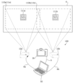
- FIG. 1 is a diagram showing an example of a projection system 100 according to an embodiment.
- the projection system 100 includes a first projection device 10a and a second projection device 10b, a computer 50, and an imaging device 30.
- FIG. Computer 50 is an example of a control device in the present invention.
- the computer 50 can communicate with the first projection device 10 a and the second projection device 10 b and the imaging device 30 .
- the computer 50 is connected to the first projection device 10a via the communication cable 8a and can communicate with the first projection device 10a.
- the computer 50 is connected to the second projection device 10b via the communication cable 8b, and can communicate with the second projection device 10b.
- the computer 50 is connected to the imaging device 30 via the communication cable 9 and can communicate with the imaging device 30 .
- the first projection device 10 a and the second projection device 10 b are projection devices capable of projecting onto the projection target 6 .
- the imaging device 30 is an imaging device capable of capturing an image projected onto the projection target 6 by the first projection device 10a and the second projection device 10b.
- the projection target 6 is an object such as a screen having a projection surface on which a projection image is displayed by the first projection device 10a.
- the projection plane of the projection target 6 is a rectangular plane. Assume that the top, bottom, left, and right of the projection object 6 in FIG. 1 are the top, bottom, left, and right of the actual projection object 6 .
- a projection range 11a illustrated by a dashed line is a region of the projection object 6 irradiated with projection light by the first projection device 10a.
- the projection range 11a is part or all of the projectable range that can be projected by the first projection device 10a.
- a projection range 11b indicated by a two-dot chain line is a region of the projection object 6 that is irradiated with projection light by the second projection device 10b.
- the projection range 11b is part or all of the projectable range that can be projected by the second projection device 10b.
- the projection ranges 11a and 11b are rectangular.
- FIG. 2 is a diagram showing an example of the first projection device 10a and the second projection device 10b.
- Each of the first projection device 10a and the second projection device 10b is configured by the projection device 10 shown in FIG. 2, for example.
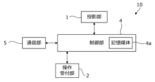
- Projection device 10 includes projection unit 1 , control unit 4 , operation reception unit 2 , and communication unit 5 .
- the projection unit 1 is configured by, for example, a liquid crystal projector or a projector using LCOS (Liquid Crystal On Silicon). In the following description, it is assumed that the projection unit 1 is a liquid crystal projector.
- LCOS Liquid Crystal On Silicon
- the control unit 4 controls projection by the projection device 10 .
- the control unit 4 includes a control unit configured by various processors, a communication interface (not shown) for communicating with each unit, and a storage medium such as a hard disk, SSD (Solid State Drive), or ROM (Read Only Memory). 4a, and controls the projection unit 1 in an integrated manner.
- various processors of the control unit of the control unit 4 the circuit configuration is changed after manufacturing such as CPU (Central Processing Unit), FPGA (Field Programmable Gate Array), which is a general-purpose processor that executes programs and performs various processes.
- Programmable Logic Device which is a processor, or a dedicated electric circuit, etc., which is a processor having a circuit configuration specially designed to execute specific processing such as ASIC (Application Specific Integrated Circuit) is included.
- ASIC Application Specific Integrated Circuit
- control unit of the control unit 4 may be composed of one of various processors, or a combination of two or more processors of the same type or different types (for example, a combination of multiple FPGAs or a combination of a CPU and an FPGA). may consist of
- the operation reception unit 2 detects instructions from the user (user instructions) by receiving various operations from the user.
- the operation reception unit 2 may be a button, key, joystick, or the like provided in the control unit 4 , or may be a reception unit or the like that receives a signal from a remote controller that remotely operates the control unit 4 .
- the communication unit 5 is a communication interface capable of communicating with the computer 50.
- the communication unit 5 may be a wired communication interface that performs wired communication as shown in FIG. 1, or a wireless communication interface that performs wireless communication.
- the projection unit 1, the control unit 4, and the operation reception unit 2 are realized by, for example, one device (see FIGS. 4 and 5, for example).
- the projection unit 1, the control unit 4, and the operation reception unit 2 may be separate devices that cooperate by communicating with each other.
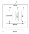
- FIG. 3 is a schematic diagram showing an example of the internal configuration of the projection unit 1.
- the projection unit 1 of the projection device 10 shown in FIG. 2 includes a light source 21, a light modulation unit 22, a projection optical system 23, and a control circuit 24, as shown in FIG.
- the light source 21 includes a light-emitting element such as a laser or an LED (Light Emitting Diode), and emits white light, for example.
- the light modulation unit 22 modulates each color light emitted from the light source 21 and separated into three colors of red, blue, and green by a color separation mechanism (not shown) based on image information, and outputs each color image. It is composed of a liquid crystal panel (light modulation element) and a dichroic prism that mixes the respective color images emitted from the three liquid crystal panels and emits them in the same direction. Red, blue, and green filters may be mounted on these three liquid crystal panels, respectively, and the white light emitted from the light source 21 may be modulated by each liquid crystal panel to emit an image of each color.
- the projection optical system 23 receives the light from the light source 21 and the light modulation section 22, and includes at least one lens and is configured by, for example, a relay optical system. The light that has passed through the projection optical system 23 is projected onto the projection object 6 .
- a region of the projection object 6 irradiated with light that passes through the entire range of the light modulation unit 22 is a projectable range that can be projected by the projection unit 1 .
- the area irradiated with the light actually transmitted from the light modulation section 22 is the projection range of the projection section 1 (projection range 11a or projection range 11b).
- the size, position, and shape of the projection range of the projection section 1 change within the projectable range.
- the control circuit 24 controls the light source 21, the light modulating unit 22, and the projection optical system 23 based on the display data input from the control unit 4, thereby displaying an image on the projection object 6 based on the display data. be projected.
- the display data to be input to the control circuit 24 is composed of red display data, blue display data, and green display data.
- control circuit 24 enlarges or reduces the projection range of the projection unit 1 by changing the projection optical system 23 based on commands input from the control unit 4 . Further, the control unit 4 may move the projection range of the projection unit 1 by changing the projection optical system 23 based on the user's operation received by the operation receiving unit 2 .
- the projection device 10 also includes a shift mechanism that mechanically or optically moves the projection range of the projection unit 1 while maintaining the image circle of the projection optical system 23 .
- the image circle of the projection optical system 23 is an area in which the projection light incident on the projection optical system 23 passes through the projection optical system 23 appropriately in terms of light falloff, color separation, peripheral curvature, and the like.
- the shift mechanism is realized by at least one of an optical system shift mechanism that performs optical system shift and an electronic shift mechanism that performs electronic shift.
- the optical system shift mechanism is, for example, a mechanism for moving the projection optical system 23 in a direction perpendicular to the optical axis (see, for example, FIGS. 5 and 20), or a mechanism for shifting the light modulation section 22 instead of moving the projection optical system 23. It is a mechanism that moves in the direction perpendicular to the axis. Further, the optical system shift mechanism may combine the movement of the projection optical system 23 and the movement of the light modulation section 22 .
- the electronic shift mechanism is a mechanism that shifts the pseudo projection range by changing the light transmission range in the light modulation section 22 .
- the first projection device 10a may include a projection direction changing mechanism that moves the projection range together with the image circle of the projection optical system 23.
- the projection direction changing mechanism is a mechanism that changes the projection direction of the projection unit 1 by changing the direction of the projection unit 1 by mechanical rotation (see FIG. 20, for example).
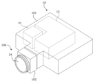
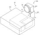
- FIG. 4 is a schematic diagram showing the external configuration of the projection device 10.
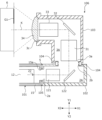
- FIG. 5 is a schematic cross-sectional view of the optical unit 106 of the projection device 10 shown in FIG. FIG. 5 shows a cross section along the optical path of light emitted from the main body 101 shown in FIG.
- the projection device 10 includes a main body 101 and an optical unit 106 protruding from the main body 101 .
- the operation reception unit 2 , the control unit 4 , the light source 21 , the light modulation unit 22 and the control circuit 24 in the projection unit 1 , and the communication unit 5 are provided in the main unit 101 .
- a projection optical system 23 in the projection unit 1 is provided in the optical unit 106 .
- the optical unit 106 includes a first member 102 supported by the body portion 101 .
- the optical unit 106 may be detachably attached to the main body 101 (in other words, replaceable).
- the main body 101 has a housing 15 in which an opening 15a for passing light is formed in a portion connected to the optical unit 106. As shown in FIG. 5, the main body 101 has a housing 15 in which an opening 15a for passing light is formed in a portion connected to the optical unit 106. As shown in FIG. 5, the main body 101 has a housing 15 in which an opening 15a for passing light is formed in a portion connected to the optical unit 106. As shown in FIG.
- a light source 21 inside the housing 15 of the main unit 101 are a light source 21 and a light modulation unit 22 ( (see FIG. 3) is provided.
- the light emitted from the light source 21 enters the light modulating section 22 of the light modulating unit 12, is spatially modulated by the light modulating section 22, and is emitted.
- an image formed by light spatially modulated by the light modulation unit 12 passes through the opening 15a of the housing 15, enters the optical unit 106, is projected onto the projection object 6,
- the image G1 becomes visible to the observer.
- the optical unit 106 includes a first member 102 having a hollow portion 2A connected to the inside of the body portion 101, a first optical system 121 arranged in the hollow portion 2A, a lens 34, a first and a shift mechanism 105 .
- the first member 102 is, for example, a member having a rectangular cross-sectional outline, and the opening 2a and the opening 2b are formed on planes parallel to each other.
- the first member 102 is supported by the body portion 101 with the opening 2a arranged at a position facing the opening 15a of the body portion 101 .
- Light emitted from the light modulating portion 22 of the light modulating unit 12 of the main body portion 101 enters the hollow portion 2A of the first member 102 through the openings 15a and 2a.
- the incident direction of light entering the hollow portion 2A from the main body portion 101 is described as the direction X1, the direction opposite to the direction X1 is described as the direction X2, and the directions X1 and X2 are collectively described as the direction X.
- the direction from the front to the back of the paper surface and the opposite direction are described as a direction Z.
- the direction from the front to the back of the paper is described as a direction Z1
- the direction from the back to the front of the paper is described as a direction Z2.
- a direction perpendicular to the direction X and the direction Z is described as a direction Y.
- the upward direction in FIG. 5 is described as a direction Y1
- the downward direction in FIG. 5 is described as a direction Y2.
- the projection device 10 is arranged such that the direction Y2 is the vertical direction.
- the projection optical system 23 shown in FIG. 3 is composed of the first optical system 121 and the lens 34 in the example of FIG.
- the optical axis K of this projection optical system 23 is shown in FIG.
- the first optical system 121 and the lens 34 are arranged along the optical axis K in this order from the light modulation section 22 side.
- the first optical system 121 includes at least one lens, and guides the light incident on the first member 102 from the main body 101 and traveling in the direction X1 to the lens 34 .
- the lens 34 is arranged at the end of the first member 102 so as to block the opening 2b formed at the end of the first member 102 on the direction X1 side.
- the lens 34 projects the light incident from the first optical system 121 onto the projection object 6 .
- the first shift mechanism 105 is a mechanism for moving the optical axis K of the projection optical system (in other words, the optical unit 106) in a direction perpendicular to the optical axis K (direction Y in FIG. 5). Specifically, the first shift mechanism 105 is configured to change the position of the first member 102 in the direction Y with respect to the body portion 101 .
- the first shift mechanism 105 may be one that moves the first member 102 manually, or one that moves the first member 102 electrically.
- FIG. 5 shows a state in which the first member 102 has been moved to the maximum extent in the direction Y1 by the first shift mechanism 105. As shown in FIG. The first member 102 is moved in the direction Y2 by the first shift mechanism 105 from the state shown in FIG. , the image G1 projected onto the projection object 6 can be shifted (translated) in the direction Y2.
- the first shift mechanism 105 may be a mechanism that moves the light modulation section 22 in the Y direction instead of moving the optical unit 106 in the Y direction. Even in this case, the image G1 projected onto the projection target 6 can be moved in the Y direction.
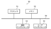
- FIG. 6 is a diagram showing an example of the hardware configuration of the computer 50.
- the computer 50 shown in FIG. 1 includes a processor 51, a memory 52, a communication interface 53, and a user interface 54, as shown in FIG.
- Processor 51 , memory 52 , communication interface 53 and user interface 54 are connected by bus 59 , for example.
- the processor 51 is a circuit that performs signal processing, such as a CPU that controls the entire computer 50 .
- the processor 51 may be realized by other digital circuits such as FPGA and DSP (Digital Signal Processor). Also, the processor 51 may be realized by combining a plurality of digital circuits.
- the memory 52 includes, for example, main memory and auxiliary memory.
- the main memory is, for example, RAM (Random Access Memory).
- the main memory is used as a work area for processor 51 .
- Auxiliary memory is non-volatile memory such as magnetic disk, optical disk, flash memory, etc.
- Various programs for operating the computer 50 are stored in the auxiliary memory. Programs stored in the auxiliary memory are loaded into the main memory and executed by the processor 51 .
- auxiliary memory may include a portable memory removable from the computer 50.
- Portable memories include memory cards such as USB (Universal Serial Bus) flash drives and SD (Secure Digital) memory cards, and external hard disk drives.
- the communication interface 53 is a communication interface that performs communication with the outside of the computer 50 (for example, the first projection device 10a, the second projection device 10b, and the imaging device 30). Communication interface 53 is controlled by processor 51 .
- the communication interface 53 may be a wired communication interface that performs wired communication, a wireless communication interface that performs wireless communication, or may include both a wired communication interface and a wireless communication interface.
- the user interface 54 includes, for example, an input device that receives operation input from the user and an output device that outputs information to the user.
- the input device can be implemented by, for example, a pointing device (eg mouse), a key (eg keyboard), a remote controller, or the like.
- An output device can be realized by, for example, a display or a speaker. Also, the input device and the output device may be implemented by a touch panel or the like.
- User interface 54 is controlled by processor 51 .
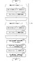
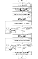
- FIG. 7 is a flow chart showing an example of control by the computer 50.
- the computer 50 executes the processing shown in FIG. 7, for example.
- a plurality of test images projected by the first projection device 10a and the second projection device 10b are prepared in advance.
- the multiple test images are test images with different combinations of colors and pixel values (brightness). Also, one test image may contain multiple regions with different combinations of colors and pixel values (brightness).
- the plurality of test images projected by the first projection device 10a and the plurality of test images projected by the second projection device 10b may be the same or different.
- the computer 50 repeatedly executes steps S71 and S72 for each of the plurality of test images projected by the first projection device 10a. That is, the computer 50 communicates with the first projection device 10a to perform control for projecting the target test image from the first projection device 10a (step S71). Projection of the test image by the first projection device 10a will be described later (see FIG. 8, for example). Next, the computer 50 controls the imaging device 30 to capture the test image projected in step S71 (step S72).
- the computer 50 repeatedly executes steps S73 and S74 for each of the plurality of test images projected by the second projection device 10b. That is, the computer 50 communicates with the second projection device 10b to perform control for projecting the target test image from the second projection device 10b (step S73). Projection of the test image by the second projection device 10b will be described later (see FIG. 9, for example). Next, the computer 50 controls the imaging device 30 to capture the test image projected in step S73 (step S74).
- the control to capture the test image with the imaging device 30 in steps S72 and S74 is, for example, control to prompt the user of the imaging device 30 to capture the test image with the imaging device 30.
- the computer 50 controls to output a message prompting the imaging device 30 to capture a test image by projection by the first projection device 10a or the second projection device 10b, display or audio output by the computer 50 or the imaging device 30, or the like. I do.
- the computer 50 receives from the imaging device 30 captured data of test images obtained by imaging in steps S72 and S74.
- the transmission of the imaging data by the imaging device 30 may be automatically performed by the imaging device 30 triggered by imaging by the imaging device 30, or may be performed by a user operation after imaging by the imaging device 30. good too. Further, the transmission of the imaging data by the imaging device 30 may be performed each time steps S71 and S72 or steps S73 and S74 are executed, or the repetition processing of steps S71 and S72 and the repetition processing of steps S73 and S74 may be performed. may be performed collectively after is performed.
- the computer 50 generates markers with different colors projected by the first projection device 10a and the second projection device 10b based on the captured data of each test image received from the imaging device 30 (step S75). . Generation of markers based on captured data of each test image will be described later.
- the process from the start of the process shown in FIG. 7 to step S75 is called marker generation process 70.
- the computer 50 communicates with the first projection device 10a and the second projection device 10b to simultaneously generate marker images including the markers generated in step S75 from the first projection device 10a and the second projection device 10b.
- Control to project onto the projection object 6 is performed (step S76). Projection of the marker image by the first projection device 10a and the second projection device 10b will be described later (see FIGS. 10 and 12, for example).
- the computer 50 controls the imaging device 30 to capture the marker image projected in step S76 (step S77).
- the control for capturing the marker image by the imaging device 30 in step S77 is the same as the control for capturing the test image by the imaging device 30 in steps S72 and S74.
- the computer 50 receives from the imaging device 30 captured data of the marker image obtained by the imaging in step S77.
- the transmission of the imaging data by the imaging device 30 may be automatically performed by the imaging device 30 triggered by imaging by the imaging device 30, or may be performed by a user operation after imaging by the imaging device 30. good too.
- the computer 50 performs control to adjust the relative projection positions of the first projection device 10a and the second projection device 10b based on the captured data of the marker image received from the imaging device 30 (step S78). End a series of processes. Adjustment of the relative projection positions of the first projection device 10a and the second projection device 10b will be described later (see FIGS. 11 and 13, for example).
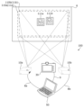
- FIG. 8 is a diagram showing an example of projection of a test image by the first projection device 10a.
- the computer 50 performs control to project the test image 80 onto the projection object 6 from the first projection device 10a.
- the test image 80 includes a red area 81, a green area 82, and a blue area 83.
- Each of r1, g1, and b1 is a value greater than 0 and less than or equal to 255, for example.
- the computer 50 controls the imaging device 30 to capture the test image 80 projected onto the projection target 6 and receives the imaging data of the test image 80 obtained by imaging from the imaging device 30 .
- the computer 50 detects a red area 81, a green area 82, and a blue area 83 from the captured data of the obtained test image 80 by image recognition (outline extraction, etc.). At this time, since the first projection device 10a is performing projection alone, the captured image does not include the projection image from the second projection device 10b, and the red region 81, the green region 82, and the blue region 83 are projected. can be detected with high accuracy.
- the computer 50 color-separates the captured data of the test image 80 into a red component (R component), a green component (G component), and a blue component (B component).
- R component red component
- G component green component
- B component blue component
- the computer 50 acquires the pixel value O P1 R
- a pixel value of a certain area is, for example, an average value or a median value of pixel values of pixels in the area.
- the computer 50 also acquires the pixel value O P1 R
- the computer 50 also acquires the pixel value O P1 R
- the computer 50 acquires the pixel value O P1 G
- the computer 50 also acquires the pixel value O P1 G
- the computer 50 also acquires the pixel value O P1 G
- the computer 50 obtains the pixel value O P1 B
- the computer 50 also acquires the pixel value O P1 B
- the computer 50 also obtains the pixel value O P1 B
- the computer 50 performs the above processing described with reference to FIG. 8 for multiple combinations of the values of r1, g1, and b1. That is, the computer 50 changes the combination of the values of r1, g1, and b1, in other words, the pixel values of the red area 81, the green area 82, and the blue area 83, while projecting the test image 80 by the first projection device 10a. , imaging of the projected test image 80 by the imaging device 30, and acquisition of each pixel value based on the imaging data obtained by the imaging.
- the computer 50 causes the first projection device 10a to project a plurality of test images 80 with different pixel values at different timings.
- the pixel value of each color component in the imaging data obtained by imaging the marker projected by the first projection device 10a can be obtained. can be done.
- a case has been described in which a plurality of test images 80 including a plurality of color regions (red region 81, green region 82, blue region 83) and having different pixel values are projected at different timings.
- a plurality of test images 80 including areas of and having different colors may be projected at different timings.
- the computer 50 causes the first projection device 10a to project a plurality of test images 80 having different combinations of pixel values and colors at different timings.
- pixel values of respective color components in imaging data obtained by imaging the markers projected by the first projection device 10a can be obtained. can be done.
- the computer 50 may also project a test image 80 including all regions of pixel value and color combinations from the first projection device 10a.
- a test image 80 including all regions of pixel value and color combinations from the first projection device 10a.
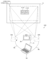
- FIG. 9 is a diagram showing an example of projection of a test image by the second projection device 10b.
- the computer 50 performs control to project the test image 90 onto the projection object 6 from the second projection device 10b.
- a test image 90 includes a red area 91 , a green area 92 and a blue area 93 .
- Each of r2, g2, and b2 is a value greater than 0 and less than or equal to 255, for example.
- the computer 50 controls the imaging device 30 to capture the test image 90 projected onto the projection target 6 and receives the imaging data of the test image 90 obtained by imaging from the imaging device 30 .
- the computer 50 detects a red area 91, a green area 92, and a blue area 93 from the captured data of the obtained test image 90 by image recognition (outline extraction, etc.). At this time, since the second projection device 10b is performing projection alone, the captured image does not include the projection image from the first projection device 10a, and the red region 91, the green region 92, and the blue region 93 are projected. can be detected with high accuracy.
- the computer 50 color-separates the imaging data of the test image 90 into a red component (R component), a green component (G component), and a blue component (B component).
- R component red component
- G component green component
- B component blue component
- the computer 50 acquires the pixel value O P2 R
- the computer 50 also acquires the pixel value O P2 R
- the computer 50 also acquires the pixel value O P2 R
- the computer 50 acquires the pixel value O P2 G
- the computer 50 also acquires the pixel value O P2 G
- the computer 50 also obtains the pixel value O P2 G
- the computer 50 acquires the pixel value O P2 B
- the computer 50 also acquires the pixel value O P2 B
- the computer 50 also acquires the pixel value O P2 B
- the computer 50 performs the above processing described with reference to FIG. 9 for multiple combinations of values of r2, g2, and b2. That is, the computer 50 changes the combination of the values of r2, g2, and b2, in other words, the pixel values of the red area 91, the green area 92, and the blue area 93, while projecting the test image 90 by the second projection device 10b. , imaging of the projected test image 90 by the imaging device 30, and acquisition of each pixel value based on the imaging data obtained by the imaging.
- the computer 50 causes the second projection device 10b to project a plurality of test images 90 with different pixel values at different timings.
- the pixel values of each color component in the imaging data obtained by imaging the marker projected by the second projection device 10b can be obtained. can be done.
- a case has been described in which a plurality of test images 90 including a plurality of color regions (red region 91, green region 92, blue region 93) and having different pixel values are projected at different timings.
- a plurality of test images 90 including the areas of and having different colors may be projected at different timings.
- the computer 50 causes the second projection device 10b to project a plurality of test images 90 with different combinations of pixel values and colors at different timings.
- the second projection device 10b For a plurality of combinations of pixel values and colors of the markers projected by the second projection device 10b, pixel values of respective color components in the imaging data obtained by imaging the markers projected by the second projection device 10b can be obtained. can be done.
- the computer 50 may also project a test image 80 including all regions of pixel value and color combinations from the first projection device 10a.
- a test image 80 including all regions of pixel value and color combinations from the first projection device 10a.
- the computer 50 stores the color of the marker projected by the first projection device 10a, the pixel value of the marker projected by the first projection device 10a, the color of the marker projected by the second projection device 10b, and the color of the marker projected by the second projection device 10b.
- a combination that satisfies a predetermined condition and has the highest evaluation value is derived from among a plurality of combinations of the pixel values of the markers to be projected.
- the above combination can be represented by the combination of (r1, g1, b1, r2, g2, b2).
- r1, g1, and b1 only one value is greater than 0 and equal to or less than 255, and the remaining values are 0.
- only one of r2, g2, and b2 is a value greater than 0 and equal to or less than 255, and the remaining values are 0.
- Equation (1) and (2) are preconditions based on the first projection device 10a projecting the red marker and the second projection device 10b projecting the blue marker.
- the following formula (3) is the value of the red component pixel value in the captured data of the red marker projected by the first projection device 10a and the pixel value of the red component in the captured data of the blue marker projected by the second projection device 10b. This is a condition for the total to be equal to or less than the maximum pixel value (255) captured by the imaging device 30 .
- the following formula (4) is a formula for the pixel value of the blue component in the imaging data of the blue marker projected by the second projection device 10b and the pixel value of the blue component in the imaging data of the red marker projected by the first projection device 10a. This is a condition for the total to be equal to or less than the maximum pixel value (255) captured by the imaging device 30 .
- the evaluation value E RG (r1, b2) in the following equation (5) is the pixel value of the red component in the captured data of the red marker projected by the first projection device 10a and the captured data of the blue marker projected by the second projection device 10b. , the pixel value of the blue component in the image data of the blue marker projected by the second projection device 10b, and the image data of the red marker projected by the first projection device 10a. and the difference (range of the blue component) from the pixel value of the blue component in .
- the computer 50 selects from among a plurality of combinations of r1 and b2 the r1 that satisfies the above formulas (1) to (4) and has the maximum evaluation value E RG (r1, b2) shown in the following formula (5). , b2.
- the computer 50 calculates the characteristics of the imaging data obtained when the first projection device 10a and the second projection device 10b project an image having a combination of characteristics (color and pixel value) based on actual measurement values of the characteristics. , derive the properties of the optimal markers projected by the first projection device 10a and the second projection device 10b.
- the evaluation value is the sum of the red component range (O P1 R
- E RG the evaluation value E RG is not limited to this.
- various representative values such as the average value, the minimum value, and the product (including the normalized product) of the red component range and the blue component range can be used.
- the minimum value of the range of the red component and the range of the blue component is set as the evaluation value ERG , and by deriving the combination of r1 and b2 that maximizes this evaluation value ERG , one of the red marker and the blue marker is separated. It is possible to avoid deriving a combination of r1 and b2 that is easy to extract but difficult to separate and extract from the other.
- the computer 50 selects from among a plurality of combinations of r1 and b2 that also satisfy the condition of the following expression (6), the evaluation value that satisfies the above expressions (1) to (4) and is shown in the above expression (5)
- a combination of r1 and b2 that maximizes E RG (r1, b2) may be derived. Thereby, the number of combinations of r1 and b2 to be evaluated can be narrowed down, and the amount of calculation can be reduced.
- the computer 50 similarly calculates other combinations of the colors of the markers projected by the first projection device 10a and the second projection device 10b. Derive a combination of pixel values. Then, the computer 50 selects a combination having the maximum evaluation value among the derived combinations of the colors and pixel values of the markers projected by the first projection device 10a and the second projection device 10b. Determine as a combination.
- the computer 50 based on the sum of the pixel values of the specific color contained in the captured data of the test images 80 and 90, sets the first projection device At least one of the pixel value and color of the marker projected by 10a and the second projection device 10b is set.
- the computer 50 calculates the first At least one of pixel values and colors of markers projected by the projection device 10a and the second projection device 10b is set.
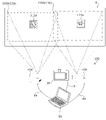
- FIG. 10 is a diagram showing an example of projection of marker images by the first projection device 10a and the second projection device 10b.
- the computer 50 performs control to simultaneously project the marker image 110a from the first projection device 10a and the marker image 110b from the second projection device 10b onto the projection object 6 .
- Projecting the marker images 110a and 110b at the same time means that there is an overlap period between the period during which the marker image 110a is projected and the period during which the marker image 110b is projected.
- the imaging of the marker images 110a and 110b is performed during this overlapping period.
- the marker image 110a is an image including a marker 111a generated as a marker projected by the first projection device 10a.
- Marker 111a is a red marker in the example of FIG.
- the marker image 110b is an image including a marker 111b generated as a marker projected by the second projection device 10b.
- Marker 111b is a green marker in the example of FIG.
- the marker 111a and the marker 111b are images of a predetermined shape that can be easily recognized by image recognition or the like.
- Markers 111a and 111b are ArUco markers in the example of FIG.
- the marker 111a and the marker 111b may be other markers such as a QR (Quick Response) code (registered trademark).
- QR Quick Response
- the marker 111a and the marker 111b have the same shape in the example of FIG. 10, they may have different shapes.
- the computer 50 controls the imaging device 30 to capture the marker images 110 a and 110 b projected onto the projection object 6 and to receive the imaging data obtained by the imaging from the imaging device 30 . Then, the computer 50 detects the markers 111a and 111b from the obtained imaging data by image recognition or the like.
- the computer 50 extracts the color (red in this example) component of the marker 111a projected by the first projection device 10a from the imaging data. Then, the computer 50 compares the pixel value of each pixel of the extracted component with a threshold value, and detects, as the marker 111a, a portion that matches the original shape of the marker 111a among the portions whose pixel value is equal to or greater than the threshold value. I do. Further, when the computer 50 cannot detect the marker 111a, the computer 50 changes the threshold value and performs the detection process again.
- the computer 50 extracts the color (green in this example) component of the marker 111b projected by the second projection device 10b from the imaging data. Then, the computer 50 performs detection processing for detecting the marker 111b based on the extracted components.
- the detection process for detecting the marker 111b is the same as the detection process for detecting the marker 111a described above.
- the markers 111a and 111b do not overlap in the example of FIG. 10, this detection can be performed with high accuracy. Further, even if the markers 111a and 111b overlap, as described above, the saturation of the pixel values of the imaging data in the overlapping portion is suppressed, and the markers 111a and 111b are arranged so as to facilitate separation and extraction of each marker. is generated, the markers 111a and 111b can be detected with high accuracy.
- the computer 50 identifies the current relative position between the projection range 11a of the first projection device 10a and the projection range 11b of the second projection device 10b based on the respective positions at which the markers 111a and 111b are detected in the imaging data.
- FIG. 11 is a diagram showing an example of projection position adjustment for stack projection.
- the entire projection range 11a of the first projection device 10a and the entirety of the second projection device 10b of the first projection device 10a are superimposed, and the same image is projected from the first projection device 10a and the second projection device 10b.
- stack projection is performed to improve dynamic range and gradation expression by projecting images.
- the computer 50 determines whether the entire projection range 11a and the entire second projection device 10b are aligned.
- the relative projection positions of the first projection device 10a and the second projection device 10b are adjusted so that they are superimposed. This adjustment can be performed, for example, by controlling the shift mechanism (optical system shift mechanism or electronic shift mechanism) of at least one of the first projection device 10a and the second projection device 10b.
- the computer 50 adjusts the projection range 11b by controlling the shift mechanism of the second projection device 10b, using the projection range 11a of the first projection device 10a as a reference, thereby adjusting the projection range.
- the entirety of 11a and the entirety of projection range 11b are superimposed to enable stack projection.
- the computer 50 calculates conversion parameters for correcting the projection range 11b so that the projection range 11b matches the projection range 11a. Transformation parameters include, for example, a homography matrix. Then, the computer 50 corrects the input image of the second projection device 10b using the calculated transformation parameter and performs projection from the second projection device 10b, thereby matching the projection range 11b with the projection range 11a. can.
- the entire projection range 11a of the first projection device 10a and the entire projection range 11b of the second projection device 10b are superimposed to obtain the first projection device 10a and the second projection device 10b.
- the form in which projection adjustment control is performed for projection by the first projection device 10a and the second projection device 10b is not limited to this. .
- the ends of the projection range 11a of the first projection device 10a and the ends of the projection range 11b of the second projection device 10b are overlapped, and divided images obtained by dividing a large image are projected by the first projection device 10a and the second projection device 10a, respectively.
- blending projection for enlarging the projection screen may be performed.
- FIG. 12 is a diagram showing an example of a state before adjusting the projection position for blending projection.
- the positions of the first projection device 10a and the second projection device 10b are adjusted so that only the ends of the projection range 11a and the ends of the projection range 11b overlap. Orientation is adjusted.
- the computer 50 generates marker images 110a and 110b including the markers 111a and 111b generated by the marker generation process 70 shown in FIG.
- the projected marker images 110a and 110b are captured by the imaging device 30, and the imaging data obtained by the imaging is received from the imaging device 30.
- the computer 50 detects the markers 111a and 111b from the obtained imaging data by image recognition or the like. Then, the computer 50 identifies the current relative position between the projection range 11a of the first projection device 10a and the projection range 11b of the second projection device 10b based on the positions at which the markers 111a and 111b are detected in the imaging data. do.
- FIG. 13 is a diagram illustrating an example of projection position adjustment for blending projection.
- the computer 50 calculates a specific region of the projection range 11a (for example, a region of a certain width at the right end).
- the relative projection positions of the first projection device 10a and the second projection device 10b are adjusted so that the second projection device 10b overlaps with the specific region (for example, the left end region of a constant width).
- the specific area of the projection range 11a and the specific area of the projection range 11b have the same size.
- the method of adjusting the relative projection positions of the first projection device 10a and the second projection device 10b is the same as in the case of stack projection.
- the computer 50 performs blending processing such as halving the brightness of the projection images from the first projection device 10a and the second projection device 10b for the overlapping portions of the projection ranges 11a and 11b. As a result, it is possible to reduce discomfort such as bright display of only the overlapping portions of the projection ranges 11a and 11b.
- the marker image 110a includes one marker 111a, but the marker image 110a may include a plurality of arranged markers 111a. Also, although the case where the marker image 110b includes one marker 111b has been described, the marker image 110b may include a plurality of arranged markers 111a.
- the computer 50 projects the test images 80 and 90 (first images) from the first projection device 10a and the second projection device 10b (a plurality of projection devices) at different timings, and projects the projected test images.
- Marker images 110a and 110b (second images) including markers 111a and 111b (markers with different colors) are simultaneously projected from the first projection device 10a and the second projection device 10b based on the imaging data of 80 and 90, respectively.
- the computer 50 sets the colors and pixel values of the markers 111a and 111b of the marker images 110a and 110b (second images) based on the imaging data of the test images 80 and 90 (first images).
- markers 111a and 111b that are easy to detect even if they overlap each other, project them at the same time, and capture an image. Therefore, the markers 111a and 111b are accurately detected from imaging data obtained by imaging the markers 111a and 111b projected simultaneously, and based on the result, the relative position of the first projection device 10a and the second projection device 10b is determined.
- the target projection position can be specified with high accuracy. Therefore, it is possible to accurately adjust the relative projection positions of the first projection device 10a and the second projection device 10b.
- the first projection device is not affected by blurring of the imaging device 30.
- the relative projection positions of 10a and second projection device 10b can be specified with high accuracy. Therefore, for example, even if the imaging by the imaging device 30 is hand-held imaging without using a tripod or a pedestal, it is possible to specify and adjust the relative projection positions of the first projection device 10a and the second projection device 10b with high accuracy. can.
- the computer 50 may set the shapes and sizes (images of the markers 111a and 111b) of the markers 111a and 111b based on the imaging data of the test images 80 and 90 (first images).
- FIG. 14 is a flow chart showing an example of optimization processing of the marker re-search range by the computer 50 .
- the computer 50 may execute the processing shown in FIG. First, the computer 50 executes marker generation processing 70 shown in FIG.
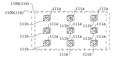
- the marker image 110a includes a plurality of arranged markers 111a
- the marker image 110b includes a plurality of arranged markers 111a (see FIG. 15, for example).
- Step S1401 the computer 50 controls the first projection device 10a and the second projection device 10b to simultaneously project the marker images 110a and 110b including the markers 111a and 111b generated by the marker generation process 70 onto the projection object 6.
- Step S1401 is the same as step S76 in FIG.
- the computer 50 controls the imaging device 30 to capture the marker images 110a and 110b projected in step S1401 (step S1402).
- Step S1402 is the same as step S77 in FIG.
- the computer 50 extracts the first color component from the imaging data obtained in step S1402 (step S1403).
- the first color component is the color component of the marker 111a generated by the marker generation process 70 and projected by the first projection device 10a.
- the computer 50 executes processing for detecting the marker of the first projection device 10a from the first color component extracted in step S1403 (step S1404).
- the computer 50 determines whether all the markers 111a included in the marker image 110a projected by the first projection device 10a in step S1401 have been detected in step S1404 (step S1405).
- step S1405 if all the markers 111a have not been detected (step S1405: No), the computer 50 changes the marker search range of the marker image 110a (step S1406) and returns to step S1404. A change in the marker search range of the marker image 110a will be described later (see FIG. 15, for example).
- step S1405 if all the markers 111a have been detected (step S1405: Yes), the computer 50 extracts the second color component from the imaging data obtained at step S1402 (step S1407).
- the second color component is the color component of the marker 111b that is generated by the marker generation process 70 and projected by the second projection device 10b.
- the computer 50 executes processing for detecting the marker of the second projection device 10b from the second color component extracted in step S1407 (step S1408).
- the computer 50 determines whether all the markers 111b included in the marker image 110b projected by the second projection device 10b in step S1401 have been detected in step S1408 (step S1409).
- step S1409 if all the markers 111b have not been detected (step S1409: No), the computer 50 changes the marker search range of the marker image 110b (step S1410) and returns to step S1408. Changes to the marker search range of the marker image 110b will be described later (see FIG. 15, for example).
- step S1409 if all the markers 111b have been detected (step S1409: Yes), the computer 50 detects the positions of the markers 111a and 111b detected in steps S1404 and S1408. Control is performed to adjust the relative projection position of the projection device 10b (step S1411), and the series of processing ends.
- Step S1411 is the same as step S78 in FIG.
- FIG. 15 is a diagram for explaining an example of optimization of the marker re-search range.
- a specific example of optimization of the marker re-search range by the processing shown in FIG. 14 will be described with reference to FIG.
- a marker image 110a including nine markers 111a arranged in a 3 ⁇ 3 matrix is projected from the first projection device 10a as shown in FIG.
- a marker image 110b including nine markers 111b arranged in a matrix of three is projected from the second projection device 10b.
- step S1406 computer 50 changes the marker search range for the first color component extracted in step S1403.
- the initial marker search range for the first color component is the entire area of the first color component.
- the computer 50 estimates the position of the undetected center marker 111a based on the positions of the detected eight markers 111a.
- the nine markers 111a are markers with different shapes.
- the computer 50 can distinguish between the detected marker 111a and the undetected marker 111a among the nine markers 111a based on the shape of the detected marker 111a. Also, the computer 50 estimates the positions of the undetected markers 111a based on the positional relationship of the nine markers 111a and the positions of the detected markers 111a.
- the computer 50 sets a range including the estimated position of the central marker 111a and narrower than the marker search range before change as the marker search range after change.
- the marker search range can be limited to a range in which the center marker 111a that has not been detected is presumed to be present.
- the computer 50 returns to step S1404 and performs processing for detecting the marker 111a from the limited marker search range of the first color component. At this time, the computer 50 repeats the process of detecting the marker 111a while changing the threshold value for distinguishing between the marker portion and other portions, for example, thereby detecting the center marker 111a that has not been detected. can be done.
- step S1410 computer 50 changes the marker search range for the second color component extracted in step S1407.
- the initial marker search range for the second color component is the entire area of the second color component.
- the computer 50 estimates the position of the undetected lower right marker 111b based on the positions of the detected eight markers 111b.
- the method of estimating the position of the undetected marker 111b is the same as the method of estimating the position of the undetected marker 111a.
- the computer 50 sets a range including the estimated position of the lower right marker 111b and narrower than the marker search range before change as the marker search range after change.
- the marker search range can be limited to a range in which the undetected lower right marker 111b is assumed to be.
- the computer 50 returns to step S1408 and performs processing for detecting the marker 111b from the limited marker search range of the second color component. At this time, the computer 50 repeats the process of detecting the marker 111b while changing the threshold value for distinguishing between the marker portion and other portions, for example, thereby detecting the undetected lower right marker 111b. be able to.
- the computer 50 detects only some of the markers 111a from the imaging data of the marker image 110a, the computer 50 detects the positions of the remaining markers 111a based on the positions of the some markers 111a.
- the residual marker 111a may be detected from the imaging data of the marker image 110a based on the result of estimating .
- the computer 50 detects only some markers 111b among the plurality of markers 111b from the imaging data of the marker image 110b, the computer 50 estimates the positions of the remaining markers 111b based on the positions of the some markers 111b. Based on the results obtained, the remaining markers 111b may be detected from the imaging data of the marker image 110a.
- the markers 111a and 111b that could not be detected by the first detection process can be detected by limiting the marker search range and performing the detection process again. Therefore, the relative projection positions of the first projection device 10a and the second projection device 10b can be accurately identified and adjusted.
- FIG. 16 is a flowchart showing an example of marker placement optimization processing by the computer 50 .
- the computer 50 may execute the processing shown in FIG. First, the computer 50 executes marker generation processing 70 shown in FIG.
- the marker image 110a includes a plurality of arranged markers 111a
- the marker image 110b includes a plurality of arranged markers 111a (see FIG. 16, for example).
- Steps S161 to S166 shown in FIG. 16 are the same as steps S1401 to S1404, S1407, and S1408 shown in FIG.
- the computer 50 determines whether or not all the markers 111a and 111b have been detected in steps S164 and S166 (step S167).
- step S167 if all the markers 111a and 111b have not been detected (step S167: No), the computer 50 changes the marker arrangement (step S168) and returns to step S161. A change in marker arrangement will be described later (see FIGS. 17 and 18, for example).
- step S167 if all the markers 111a and 111b have been detected (step S167: Yes), the computer 50 detects the positions of the markers 111a and 111b detected in steps S164 and S166. Control is performed to adjust the relative projection position of the second projection device 10b (step S169), and the series of processing ends. Step S169 is the same as step S78 in FIG.
- ⁇ Optimization of marker placement> 17 and 18 are diagrams for explaining an example of optimization of marker placement. 17 and 18, a specific example of optimizing the marker arrangement by the processing shown in FIG. 16 will be described.
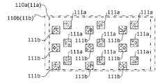
- step S161 shown in FIG. 16 as shown in FIG. 17, a marker image 110a including nine markers 111a is projected from the first projector 10a, and a marker image 110b including nine markers 111b is projected from the first projection device 10a. 2 projected from the projection device 10b.
- the overlapping portion between the nine markers 111a and the nine markers 111b is large, and at least one (for example, all) of the markers 111a and 111b was not detected in steps S164 and S166. do.
- the computer 50 changes the marker placement of at least one of the marker images 110a and 110b in step S168.
- the marker arrangement of the marker image 110a is the position of the marker 111a in the marker image 110a.
- the marker placement of marker image 110b is the position of marker 111b in marker image 110b.
- the marker arrangement of the marker 111a and the marker arrangement of the marker image 110b are predetermined in multiple ways.
- the computer 50 changes the marker arrangement of the marker image 110b without changing the marker arrangement of the marker image 110a.
- the marker 111b of the marker image 110b shifts to the lower left from the state shown in FIG. 17, the overlapping portion between the marker 111a and the marker 111b disappears, and all of the markers 111a and 111b can be detected.
- the overlapping portion between the markers 111a and 111b is eliminated in the example of FIG. 18, the overlapping portion between the markers 111a and 111b may not be eliminated even if the marker arrangement is changed. However, since the marker 111a and the marker 111b are generated so that saturation of the pixel values of the imaging data in the overlapping portion is suppressed and the separate extraction of each marker is easy, the overlapping portion can be reduced by changing the marker arrangement. If so, there is a high possibility that all of the markers 111a and 111b can be detected.
- the computer 50 repeats changing the marker arrangement until all the markers 111a and 111b are detected.
- the computer 50 generates the marker images 110a and 110b with the positions of the markers 111a and 111b changed based on the detection results of the markers 111a and 111b from the imaging data of the marker images 110a and 110b. Projection may be performed from at least one of the second projection devices 10b.
- the markers 111a and 111b that could not be detected by the first detection process can be detected by limiting the marker arrangement and performing the detection process again. Therefore, the relative projection positions of the first projection device 10a and the second projection device 10b can be accurately identified and adjusted.
- the computer 50 performs processing to change the images of the markers 111a and 111b (for example, at least one of shape, size, and orientation). good too.
- the optimization of the marker re-search range described in FIGS. 14 and 15 and the optimization of the marker arrangement described in FIGS. 16 to 18 may be used together.
- the computer 50 may optimize the marker arrangement when all the markers cannot be detected even after optimizing the marker re-search range a predetermined number of times.
- the loop processing of steps S1404 to S1406 and the loop processing of steps S1408 to S1410 are each provided with an upper limit for the number of loops.
- 16 step S168 may be executed and the process may proceed to step S1401.
- FIG. 19 is a schematic diagram showing another external configuration of the projection device 10.
- FIG. FIG. 20 is a schematic cross-sectional view of the optical unit 106 of the projection device 10 shown in FIG.
- the same parts as those shown in FIGS. 4 and 5 are denoted by the same reference numerals, and description thereof is omitted.
- the optical unit 106 includes a second member 103 supported by the first member 102 in addition to the first member 102 supported by the main body portion 101 .
- the first member 102 and the second member 103 may be an integrated member.
- the optical unit 106 includes, in addition to the first member 102, a second member 103 having a hollow portion 3A connected to the hollow portion 2A of the first member 102, and a first member 103 arranged in the hollow portion 2A.
- the openings 2a and 2b of the first member 102 are formed on planes perpendicular to each other.
- the projection optical system 23 shown in FIGS. It is configured by the third optical system 33 .
- the optical axis K is folded back by being bent twice.
- the first optical system 121, the reflecting member 122, the second optical system 31, the reflecting member 32, the third optical system 33, and the lens 34 are arranged along the optical axis K in this order from the light modulation section 22 side.
- the first optical system 121 guides the light that has entered the first member 102 from the main body 101 and travels in the direction X1 to the reflecting member 122 .
- the reflecting member 122 reflects the light incident from the first optical system 121 in the direction Y1.
- the reflecting member 122 is composed of, for example, a mirror.
- the first member 102 has an opening 2b on the optical path of the light reflected by the reflecting member 122, and the reflected light passes through the opening 2b and advances to the hollow portion 3A of the second member 103.
- the second member 103 is a member having a substantially L-shaped cross-sectional outline, and an opening 3a is formed at a position facing the opening 2b of the first member 102.
- the light from the body portion 101 that has passed through the opening 2b of the first member 102 enters the hollow portion 3A of the second member 103 through this opening 3a.
- the cross-sectional outlines of the first member 102 and the second member 103 are arbitrary, and are not limited to those described above.
- the second optical system 31 includes at least one lens and guides light incident from the first member 102 to the reflecting member 32 .
- the reflecting member 32 reflects the light incident from the second optical system 31 in the direction X ⁇ b>2 and guides it to the third optical system 33 .
- the reflecting member 32 is composed of, for example, a mirror.
- the third optical system 33 includes at least one lens and guides the light reflected by the reflecting member 32 to the lens 34 .
- the lens 34 is arranged at the end of the second member 103 in the direction X2 so as to block the opening 3c formed at the end.
- the lens 34 projects the light incident from the third optical system 33 onto the projection object 6 .
- FIG. 20 shows a state in which the first member 102 has been moved to the maximum extent in the direction Y1 by the first shift mechanism 105.
- the projection direction changing mechanism 104 is a rotating mechanism that rotatably connects the second member 103 to the first member 102 .
- the projection direction changing mechanism 104 allows the second member 103 to rotate about a rotation axis extending in the direction Y (specifically, the optical axis K).
- the projection direction changing mechanism 104 is not limited to the arrangement position shown in FIG. 20 as long as it can rotate the optical system.
- the number of rotating mechanisms is not limited to one, and a plurality of rotating mechanisms may be provided.
- the control device of the present invention may be the first projection device 10a or the second projection device 10b.
- each control by the computer 50 is performed by the first projection device 10a or the second projection device 10b.
- the first projection device 10 a or the second projection device 10 b may communicate with the imaging device 30 via the computer 50 or may communicate with the imaging device 30 without the computer 50 .
- the projection system 100 may be configured without the computer 50.
- control device of the present invention may be the imaging device 30.
- each control by the computer 50 is performed by the imaging device 30 .
- the imaging device 30 may communicate with the first projection device 10a and the second projection device 10b via the computer 50, or may communicate with the first projection device 10a and the second projection device 10b without the computer 50. If the imaging device 30 communicates with the first projection device 10a and the second projection device 10b without using the computer 50, the projection system 100 may be configured without the computer 50.
- ⁇ Modification 3> A case has been described in which the imaging of the test image 80, the imaging of the test image 90, and the imaging of the marker images 110a and 110b are performed by one imaging device 30, but these imagings may be performed by different imaging devices. However, in this case, it is desirable that the imaging characteristics of each imaging device be the same or similar.
- the plurality of projection devices may be three or more projection devices (N number of projection devices). There may be.
- the relative projection positions are adjusted in the same manner as the first projection device 10a and the second projection device 10b. By doing so, it is possible to adjust the relative projection positions of the N projection devices.
- the test images are projected and captured in the same manner as the test images 80 and 90 of the first projection device 10a and the second projection device 10b are projected and captured.
- simultaneous projection and imaging of the marker images may be performed in the same manner as the simultaneous projection and imaging of the marker images 110a and 110b by the first projection device 10a and the second projection device 10b.
- the predetermined conditions and evaluation values described above take into consideration that the N number of projection devices simultaneously project the marker images.
- ⁇ Modification 5> When setting a combination of pixel values and colors of the markers 111a and 111b projected by the first projection device 10a and the second projection device 10b, for example, r1, g1, b1, r2, g2, b2) by deriving a combination of r2, g2, b2) to suppress the saturation of the pixel values of the imaging data in the overlapped portion of the markers 111a and 111b.
- the method is not limited.
- the computer 50 may perform control such that the imaging of the test images 80 and 90 by the imaging device 30 is performed under a plurality of exposure conditions.
- the computer 50 selects the brightest exposure condition among the exposure conditions where there is no combination of (r1, g1, b1, r2, g2, b2) that does not satisfy the above expressions (3) and (4). It is set as the exposure condition of the device 30 .
- the computer 50 first causes the first projection device 10a and the second projection device 10b to project only the test images 80 and 90 with relatively high pixel values, which tend to cause saturation of pixel values, as described above.
- the test images 80, 90 for each combination of (r1, g1, b1, r2, g2, b2) are limited to the first projection device 10a and the second projection device 10b. You can project.
- the computer 50 sets the exposure conditions of the imaging device 30 so as to satisfy, for example, the above equations (3) and (4) based on the sum of the pixel values of the specific color included in the captured data of the test images 80 and 90. may be set.
- the computer 50 satisfies a predetermined condition (for example, the above formulas (1) and (2)) and the evaluation value (for example, the above formula (5)) is the maximum based on each imaging data acquired under the set exposure conditions.
- a predetermined condition for example, the above formulas (1) and (2)
- the evaluation value for example, the above formula (5)
- a combination of (r1, g1, b1, r2, g2, b2) is derived.
- a controller comprising a processor, The above processor Projecting the first image from a plurality of projection devices at different timings, Projecting a second image including markers of different colors from at least two or more of the plurality of projection devices based on the imaging data of the projected first image; Adjusting the relative projection positions of the plurality of projection devices based on the imaging data of the projected second image; Control device that controls.
- control device sets a pixel value of the marker in the second image based on the imaging data of the first image. Control device that controls.
- control device sets the color of the marker in the second image based on the imaging data of the first image. Control device that controls.
- the control device sets the image of the marker in the second image based on the imaging data of the first image. Control device that controls.
- the control device sets exposure conditions of an imaging device that captures the first image and the second image based on the sum of pixel values of a specific color included in the imaging data of the first image. Control device that controls.
- the control device includes a first projection device and a second projection device;
- the above processor A pixel value of a first color included in captured data of the first image projected by the first projection device, and a pixel of the first color included in captured data of the first image projected by the second projection device. setting the exposure conditions based on the values of Control device that controls.
- the control device A pixel value of a second color included in captured data of the first image projected by the first projection device, and a pixel of the second color included in captured data of the first image projected by the second projection device. setting the exposure conditions based on the values of Control device that controls.
- the control device sets at least one or more of the pixel value and color of the marker in the second image and the image based on the sum of the pixel values of the specific color included in the captured data of the first image. Control device that controls.
- the control device includes a first projection device and a second projection device;
- the above processor A pixel value of a first color included in captured data of the first image projected by the first projection device, and a pixel of the first color included in captured data of the first image projected by the second projection device. setting the pixel value and/or color and image of the marker in the second image based on a value; Control device that controls.
- the control device according to The above processor A pixel value of a second color included in captured data of the first image projected by the first projection device, and a pixel of the second color included in captured data of the first image projected by the second projection device. a value and setting the pixel value and/or color and image of the marker in the second image based on Control device that controls.
- control device (11) The control device according to any one of (2) to (10), The processor, based on the magnitude of the difference in pixel values of the specific color included in the captured data of the first image projected from the plurality of projection devices, the pixel value and color of the marker in the second image, and setting at least one or more of the images; Control device that controls.
- the control device includes a first projection device and a second projection device;
- the above processor A pixel value of a first color included in captured data of the first image projected by the first projection device, and a pixel of the first color included in captured data of the first image projected by the second projection device. the magnitude of the difference between the value and setting pixel values and colors of the markers in the second image and at least one of the images based on Control device that controls.
- the control device according to any one of (1) to (13),
- the processor causes the plurality of projection devices to project, at different timings, the plurality of first images in which at least one or more of pixel values, colors, and images are different.
- Control device that controls.
- control device The control device according to any one of (1) to (14), The above processor projecting from the plurality of projection devices the first image including a plurality of regions in which at least one or more of pixel values, colors, and images are different; Control device that controls.
- the control device according to any one of (1) to (15), The processor adjusts the relative projection positions of the plurality of projection devices based on the result of detecting the marker from the imaging data of the second image. Control device that controls.
- the control device includes a plurality of markers, When the processor detects some of the plurality of markers from the captured data of the second image, the processor estimates the positions of the remaining markers based on the positions of the some markers, detecting the residual marker from the imaging data of the second image; Control device that controls.
- the control device causes at least one of the plurality of projection devices to project the second image in which the arrangement or image of the marker is changed based on the detection result of the marker from the imaging data of the second image.
- Control device that controls.
- a processor included in the control device Projecting the first image from a plurality of projection devices at different timings, Projecting a second image including markers of different colors from at least two or more of the plurality of projection devices based on the imaging data of the projected first image; Adjusting the relative projection positions of the plurality of projection devices based on the imaging data of the projected second image; Control method to control.
- the processor provided in the control device, Projecting the first image from a plurality of projection devices at different timings, Projecting a second image including markers of different colors from at least two or more of the plurality of projection devices based on the imaging data of the projected first image; Adjusting the relative projection positions of the plurality of projection devices based on the imaging data of the projected second image; A control program for executing control.
- (21) a plurality of projection devices; a controller comprising a processor;
- a projection system comprising: The above processor Projecting the first image from the plurality of projection devices at different timings, Projecting a second image including markers of different colors from at least two or more of the plurality of projection devices based on the imaging data of the projected first image; Adjusting the relative projection positions of the plurality of projection devices based on the imaging data of the projected second image; Projection system to control.
Landscapes
- Engineering & Computer Science (AREA)
- Multimedia (AREA)
- Signal Processing (AREA)
- Physics & Mathematics (AREA)
- General Physics & Mathematics (AREA)
- Health & Medical Sciences (AREA)
- General Health & Medical Sciences (AREA)
- Biomedical Technology (AREA)
- Computer Hardware Design (AREA)
- Theoretical Computer Science (AREA)
- Projection Apparatus (AREA)
- Video Image Reproduction Devices For Color Tv Systems (AREA)
- Controls And Circuits For Display Device (AREA)
Priority Applications (3)
| Application Number | Priority Date | Filing Date | Title |
|---|---|---|---|
| JP2023549407A JP7505129B2 (ja) | 2021-09-27 | 2022-08-10 | 制御装置、制御方法、制御プログラム、及び投影システム |
| CN202280064926.XA CN118044181A (zh) | 2021-09-27 | 2022-08-10 | 控制装置、控制方法、控制程序及投影系统 |
| US18/595,512 US20240214531A1 (en) | 2021-09-27 | 2024-03-05 | Control device, control method, control program, and projection system |
Applications Claiming Priority (2)
| Application Number | Priority Date | Filing Date | Title |
|---|---|---|---|
| JP2021157091 | 2021-09-27 | ||
| JP2021-157091 | 2021-09-27 |
Related Child Applications (1)
| Application Number | Title | Priority Date | Filing Date |
|---|---|---|---|
| US18/595,512 Continuation US20240214531A1 (en) | 2021-09-27 | 2024-03-05 | Control device, control method, control program, and projection system |
Publications (1)
| Publication Number | Publication Date |
|---|---|
| WO2023047833A1 true WO2023047833A1 (ja) | 2023-03-30 |
Family
ID=85719424
Family Applications (1)
| Application Number | Title | Priority Date | Filing Date |
|---|---|---|---|
| PCT/JP2022/030619 Ceased WO2023047833A1 (ja) | 2021-09-27 | 2022-08-10 | 制御装置、制御方法、制御プログラム、及び投影システム |
Country Status (4)
| Country | Link |
|---|---|
| US (1) | US20240214531A1 (cg-RX-API-DMAC7.html) |
| JP (1) | JP7505129B2 (cg-RX-API-DMAC7.html) |
| CN (1) | CN118044181A (cg-RX-API-DMAC7.html) |
| WO (1) | WO2023047833A1 (cg-RX-API-DMAC7.html) |
Cited By (1)
| Publication number | Priority date | Publication date | Assignee | Title |
|---|---|---|---|---|
| CN117572716A (zh) * | 2024-01-17 | 2024-02-20 | 厦门冠军时代科技有限公司 | 一种多光源艺术图形户外激光投影灯具 |
Families Citing this family (1)
| Publication number | Priority date | Publication date | Assignee | Title |
|---|---|---|---|---|
| JP2024142655A (ja) * | 2023-03-30 | 2024-10-11 | セイコーエプソン株式会社 | 投射画像の調整方法、プロジェクションシステム、情報処理装置、及びプログラム |
Citations (2)
| Publication number | Priority date | Publication date | Assignee | Title |
|---|---|---|---|---|
| JP2011029727A (ja) * | 2009-07-21 | 2011-02-10 | Canon Inc | 画像投射装置 |
| JP2014010264A (ja) * | 2012-06-29 | 2014-01-20 | Jvc Kenwood Corp | 画像投写位置調整装置及び画像投写位置調整方法 |
-
2022
- 2022-08-10 JP JP2023549407A patent/JP7505129B2/ja active Active
- 2022-08-10 CN CN202280064926.XA patent/CN118044181A/zh active Pending
- 2022-08-10 WO PCT/JP2022/030619 patent/WO2023047833A1/ja not_active Ceased
-
2024
- 2024-03-05 US US18/595,512 patent/US20240214531A1/en active Pending
Patent Citations (2)
| Publication number | Priority date | Publication date | Assignee | Title |
|---|---|---|---|---|
| JP2011029727A (ja) * | 2009-07-21 | 2011-02-10 | Canon Inc | 画像投射装置 |
| JP2014010264A (ja) * | 2012-06-29 | 2014-01-20 | Jvc Kenwood Corp | 画像投写位置調整装置及び画像投写位置調整方法 |
Cited By (2)
| Publication number | Priority date | Publication date | Assignee | Title |
|---|---|---|---|---|
| CN117572716A (zh) * | 2024-01-17 | 2024-02-20 | 厦门冠军时代科技有限公司 | 一种多光源艺术图形户外激光投影灯具 |
| CN117572716B (zh) * | 2024-01-17 | 2024-05-03 | 厦门冠军时代科技有限公司 | 一种多光源艺术图形户外激光投影灯具 |
Also Published As
| Publication number | Publication date |
|---|---|
| JP7505129B2 (ja) | 2024-06-24 |
| JPWO2023047833A1 (cg-RX-API-DMAC7.html) | 2023-03-30 |
| CN118044181A (zh) | 2024-05-14 |
| US20240214531A1 (en) | 2024-06-27 |
Similar Documents
| Publication | Publication Date | Title |
|---|---|---|
| JP3925521B2 (ja) | スクリーンの一部の辺を用いたキーストーン補正 | |
| US20180321761A1 (en) | Position detecting device, position detecting system, and controlling method of position detecting device | |
| JP5938638B2 (ja) | インタラクティブプレゼンシステム | |
| CN102365866B (zh) | 多投影显示系统和屏幕形成方法 | |
| US9753580B2 (en) | Position detecting device, position detecting system, and controlling method of position detecting device | |
| JP2005020314A (ja) | 表示特性補正データの算出方法、表示特性補正データの算出プログラム、表示特性補正データの算出装置 | |
| KR101691880B1 (ko) | 자동 캘리브레이션 기능이 구비된 인터액티브 시스템 및 인터액티브 시스템의 자동 캘리브레이션 방법 | |
| JP2003234983A (ja) | プロジェクタ | |
| JP7505129B2 (ja) | 制御装置、制御方法、制御プログラム、及び投影システム | |
| JP2022092132A (ja) | 表示方法、検出装置、および、プログラム | |
| CN104658462B (zh) | 投影机以及投影机的控制方法 | |
| JP2017072795A (ja) | プロジェクター、及び、プロジェクターの制御方法。 | |
| JP2019220887A (ja) | 画像処理装置、画像処理方法およびプログラム | |
| JP6836176B2 (ja) | 表示装置及び表示装置の制御方法 | |
| JP2020160808A (ja) | 位置検出方法、位置検出装置、及び、インタラクティブプロジェクター | |
| US12587619B2 (en) | Method of adjusting projection image, projection system, and control apparatus | |
| JP2020039082A (ja) | 表示装置、表示システムおよび表示装置の制御方法 | |
| JP2022077773A (ja) | 投射制御装置、画像投射システム、投射制御装置の作動方法、およびプログラム | |
| JP2019192997A (ja) | 投影制御装置及び投影制御方法 | |
| JP7228112B2 (ja) | 投影制御装置、投影装置、投影方法及びプログラム | |
| US11895444B2 (en) | Control device, control method, projection system, and control program | |
| JP6390163B2 (ja) | 情報処理装置、情報処理方法およびプログラム | |
| US9958958B2 (en) | Interactive projector and method of controlling interactive projector | |
| JP6604528B2 (ja) | 画像処理装置及び画像処理システム | |
| JP7347205B2 (ja) | 投写システムの制御方法、投写システム及び制御プログラム |
Legal Events
| Date | Code | Title | Description |
|---|---|---|---|
| 121 | Ep: the epo has been informed by wipo that ep was designated in this application |
Ref document number: 22872589 Country of ref document: EP Kind code of ref document: A1 |
|
| WWE | Wipo information: entry into national phase |
Ref document number: 2023549407 Country of ref document: JP |
|
| WWE | Wipo information: entry into national phase |
Ref document number: 202280064926.X Country of ref document: CN |
|
| NENP | Non-entry into the national phase |
Ref country code: DE |
|
| 122 | Ep: pct application non-entry in european phase |
Ref document number: 22872589 Country of ref document: EP Kind code of ref document: A1 |