WO2023047731A1 - 粘着剤層付光学積層体の製造方法 - Google Patents
粘着剤層付光学積層体の製造方法 Download PDFInfo
- Publication number
- WO2023047731A1 WO2023047731A1 PCT/JP2022/025075 JP2022025075W WO2023047731A1 WO 2023047731 A1 WO2023047731 A1 WO 2023047731A1 JP 2022025075 W JP2022025075 W JP 2022025075W WO 2023047731 A1 WO2023047731 A1 WO 2023047731A1
- Authority
- WO
- WIPO (PCT)
- Prior art keywords
- adhesive layer
- cutting
- end mill
- manufacturing
- optical
- Prior art date
- Legal status (The legal status is an assumption and is not a legal conclusion. Google has not performed a legal analysis and makes no representation as to the accuracy of the status listed.)
- Ceased
Links
Images





Classifications
-
- B—PERFORMING OPERATIONS; TRANSPORTING
- B23—MACHINE TOOLS; METAL-WORKING NOT OTHERWISE PROVIDED FOR
- B23C—MILLING
- B23C3/00—Milling particular work; Special milling operations; Machines therefor
- B23C3/13—Surface milling of plates, sheets or strips
-
- B—PERFORMING OPERATIONS; TRANSPORTING
- B23—MACHINE TOOLS; METAL-WORKING NOT OTHERWISE PROVIDED FOR
- B23C—MILLING
- B23C5/00—Milling-cutters
- B23C5/02—Milling-cutters characterised by the shape of the cutter
- B23C5/10—Shank-type cutters, i.e. with an integral shaft
-
- B—PERFORMING OPERATIONS; TRANSPORTING
- B23—MACHINE TOOLS; METAL-WORKING NOT OTHERWISE PROVIDED FOR
- B23C—MILLING
- B23C5/00—Milling-cutters
- B23C5/02—Milling-cutters characterised by the shape of the cutter
- B23C5/10—Shank-type cutters, i.e. with an integral shaft
- B23C5/1009—Ball nose end mills
-
- B—PERFORMING OPERATIONS; TRANSPORTING
- B24—GRINDING; POLISHING
- B24B—MACHINES, DEVICES, OR PROCESSES FOR GRINDING OR POLISHING; DRESSING OR CONDITIONING OF ABRADING SURFACES; FEEDING OF GRINDING, POLISHING, OR LAPPING AGENTS
- B24B7/00—Machines or devices designed for grinding plane surfaces on work, including polishing plane glass surfaces; Accessories therefor
- B24B7/10—Single-purpose machines or devices
- B24B7/16—Single-purpose machines or devices for grinding end-faces, e.g. of gauges, rollers, nuts, piston rings
-
- B—PERFORMING OPERATIONS; TRANSPORTING
- B24—GRINDING; POLISHING
- B24B—MACHINES, DEVICES, OR PROCESSES FOR GRINDING OR POLISHING; DRESSING OR CONDITIONING OF ABRADING SURFACES; FEEDING OF GRINDING, POLISHING, OR LAPPING AGENTS
- B24B7/00—Machines or devices designed for grinding plane surfaces on work, including polishing plane glass surfaces; Accessories therefor
- B24B7/20—Machines or devices designed for grinding plane surfaces on work, including polishing plane glass surfaces; Accessories therefor characterised by a special design with respect to properties of the material of non-metallic articles to be ground
- B24B7/30—Machines or devices designed for grinding plane surfaces on work, including polishing plane glass surfaces; Accessories therefor characterised by a special design with respect to properties of the material of non-metallic articles to be ground for grinding plastics
-
- B—PERFORMING OPERATIONS; TRANSPORTING
- B24—GRINDING; POLISHING
- B24D—TOOLS FOR GRINDING, BUFFING OR SHARPENING
- B24D5/00—Bonded abrasive wheels, or wheels with inserted abrasive blocks, designed for acting only by their periphery; Bushings or mountings therefor
-
- B—PERFORMING OPERATIONS; TRANSPORTING
- B32—LAYERED PRODUCTS
- B32B—LAYERED PRODUCTS, i.e. PRODUCTS BUILT-UP OF STRATA OF FLAT OR NON-FLAT, e.g. CELLULAR OR HONEYCOMB, FORM
- B32B27/00—Layered products comprising a layer of synthetic resin
- B32B27/36—Layered products comprising a layer of synthetic resin comprising polyesters
-
- B—PERFORMING OPERATIONS; TRANSPORTING
- B32—LAYERED PRODUCTS
- B32B—LAYERED PRODUCTS, i.e. PRODUCTS BUILT-UP OF STRATA OF FLAT OR NON-FLAT, e.g. CELLULAR OR HONEYCOMB, FORM
- B32B37/00—Methods or apparatus for laminating, e.g. by curing or by ultrasonic bonding
- B32B37/12—Methods or apparatus for laminating, e.g. by curing or by ultrasonic bonding characterised by using adhesives
-
- B—PERFORMING OPERATIONS; TRANSPORTING
- B32—LAYERED PRODUCTS
- B32B—LAYERED PRODUCTS, i.e. PRODUCTS BUILT-UP OF STRATA OF FLAT OR NON-FLAT, e.g. CELLULAR OR HONEYCOMB, FORM
- B32B37/00—Methods or apparatus for laminating, e.g. by curing or by ultrasonic bonding
- B32B37/14—Methods or apparatus for laminating, e.g. by curing or by ultrasonic bonding characterised by the properties of the layers
- B32B37/26—Methods or apparatus for laminating, e.g. by curing or by ultrasonic bonding characterised by the properties of the layers with at least one layer which influences the bonding during the lamination process, e.g. release layers or pressure equalising layers
-
- B—PERFORMING OPERATIONS; TRANSPORTING
- B32—LAYERED PRODUCTS
- B32B—LAYERED PRODUCTS, i.e. PRODUCTS BUILT-UP OF STRATA OF FLAT OR NON-FLAT, e.g. CELLULAR OR HONEYCOMB, FORM
- B32B38/00—Ancillary operations in connection with laminating processes
- B32B38/04—Punching, slitting or perforating
-
- B—PERFORMING OPERATIONS; TRANSPORTING
- B32—LAYERED PRODUCTS
- B32B—LAYERED PRODUCTS, i.e. PRODUCTS BUILT-UP OF STRATA OF FLAT OR NON-FLAT, e.g. CELLULAR OR HONEYCOMB, FORM
- B32B7/00—Layered products characterised by the relation between layers; Layered products characterised by the relative orientation of features between layers, or by the relative values of a measurable parameter between layers, i.e. products comprising layers having different physical, chemical or physicochemical properties; Layered products characterised by the interconnection of layers
- B32B7/02—Physical, chemical or physicochemical properties
- B32B7/023—Optical properties
-
- B—PERFORMING OPERATIONS; TRANSPORTING
- B32—LAYERED PRODUCTS
- B32B—LAYERED PRODUCTS, i.e. PRODUCTS BUILT-UP OF STRATA OF FLAT OR NON-FLAT, e.g. CELLULAR OR HONEYCOMB, FORM
- B32B7/00—Layered products characterised by the relation between layers; Layered products characterised by the relative orientation of features between layers, or by the relative values of a measurable parameter between layers, i.e. products comprising layers having different physical, chemical or physicochemical properties; Layered products characterised by the interconnection of layers
- B32B7/04—Interconnection of layers
- B32B7/06—Interconnection of layers permitting easy separation
-
- B—PERFORMING OPERATIONS; TRANSPORTING
- B32—LAYERED PRODUCTS
- B32B—LAYERED PRODUCTS, i.e. PRODUCTS BUILT-UP OF STRATA OF FLAT OR NON-FLAT, e.g. CELLULAR OR HONEYCOMB, FORM
- B32B7/00—Layered products characterised by the relation between layers; Layered products characterised by the relative orientation of features between layers, or by the relative values of a measurable parameter between layers, i.e. products comprising layers having different physical, chemical or physicochemical properties; Layered products characterised by the interconnection of layers
- B32B7/04—Interconnection of layers
- B32B7/12—Interconnection of layers using interposed adhesives or interposed materials with bonding properties
-
- G—PHYSICS
- G02—OPTICS
- G02B—OPTICAL ELEMENTS, SYSTEMS OR APPARATUS
- G02B5/00—Optical elements other than lenses
- G02B5/30—Polarising elements
-
- B—PERFORMING OPERATIONS; TRANSPORTING
- B32—LAYERED PRODUCTS
- B32B—LAYERED PRODUCTS, i.e. PRODUCTS BUILT-UP OF STRATA OF FLAT OR NON-FLAT, e.g. CELLULAR OR HONEYCOMB, FORM
- B32B37/00—Methods or apparatus for laminating, e.g. by curing or by ultrasonic bonding
- B32B37/14—Methods or apparatus for laminating, e.g. by curing or by ultrasonic bonding characterised by the properties of the layers
- B32B37/26—Methods or apparatus for laminating, e.g. by curing or by ultrasonic bonding characterised by the properties of the layers with at least one layer which influences the bonding during the lamination process, e.g. release layers or pressure equalising layers
- B32B2037/268—Release layers
-
- B—PERFORMING OPERATIONS; TRANSPORTING
- B32—LAYERED PRODUCTS
- B32B—LAYERED PRODUCTS, i.e. PRODUCTS BUILT-UP OF STRATA OF FLAT OR NON-FLAT, e.g. CELLULAR OR HONEYCOMB, FORM
- B32B38/00—Ancillary operations in connection with laminating processes
- B32B38/04—Punching, slitting or perforating
- B32B2038/047—Perforating
Definitions
- the present invention relates to a method for producing an optical laminate with an adhesive layer.
- the optical layered body includes an adhesive layer for bonding a front plate (e.g., cover glass) as one of the outermost layers, and an adhesive layer for bonding the optical layered body to an image display panel as the other outermost layer. is provided with another adhesive layer.
- a release liner is releasably attached temporarily to these adhesive layers to protect these adhesive layers until they are actually used.
- Such a processing method includes, for example, end face cutting using an end mill.
- the present invention has been made to solve such problems, and its main object is to provide a simple method for producing a pressure-sensitive adhesive layer-attached optical laminate in which lifting of a release liner is suppressed. .
- a method for producing an optical layered body with an adhesive layer includes forming a work by alternately stacking a plurality of optical layered bodies with an adhesive layer and a plurality of intervening films; cutting the outer peripheral surface of the
- the intervening film has a thickness of 75 ⁇ m to 1000 ⁇ m.
- the intervening film is made of a polyester-based resin.
- the pressure-sensitive adhesive layer-attached optical laminate comprises an optical film, a first pressure-sensitive adhesive layer having a thickness of 50 ⁇ m or more disposed on one side of the optical film, and the first A first release liner releasably temporarily attached to the adhesive layer, a second adhesive layer disposed on the other side of the optical film, and a releasable temporary adhesive layer attached to the second adhesive layer. and an attached second release liner, wherein the release force of the first release liner is greater than the release force of the second release liner.
- the optical film includes a polarizer and a retardation layer in order from the first pressure-sensitive adhesive layer side.
- cutting the workpiece includes cutting with an end mill.
- the end mill has helical blades and the pocket area per blade is 5 mm 2 or more. In one embodiment, the end mill has an outer diameter of 10 mm to 20 mm. In one embodiment, the cutting with the end mill includes cutting with a twist file. In one embodiment, the cutting with the end mill includes rough cutting with an end mill having a helical edge and finish cutting with a helical file.
- a work is formed by alternately stacking a plurality of pressure-sensitive adhesive layer-attached optical laminates and a plurality of intervening films, and the outer peripheral surface of the work is cut to form a release liner. It is possible to realize a simple method for producing an optical layered body with a pressure-sensitive adhesive layer in which floating is suppressed.
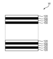
- FIG. 4 is a schematic front view of a main part for explaining a work forming method in the manufacturing method according to the embodiment of the present invention.
- BRIEF DESCRIPTION OF THE DRAWINGS It is a schematic sectional drawing explaining an example of the optical laminated body with an adhesive layer which can be used for the manufacturing method by embodiment of this invention.
- 1 is a schematic perspective view for explaining the structure of an end mill having a helical edge that can be used for cutting in a manufacturing method according to an embodiment of the present invention;
- FIG. 4 is a schematic plan view seen from the rotation axis direction for explaining the pocket area of an end mill having a helical edge that can be used for cutting in the manufacturing method according to the embodiment of the present invention
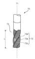
- FIG. 4 is a schematic perspective view for explaining the structure of a twist file that can be used for end surface processing in the manufacturing method according to the embodiment of the present invention
- It is a schematic diagram for explaining a twist file which does not have a relief angle in one mode of a manufacturing method by an embodiment of the present invention.
- FIG. 7 is a schematic cross-sectional view of a main part for explaining the depth and pitch of the unevenness of the file portion in the twist file of FIG. 6 ;
- a method for producing an optical layered body with an adhesive layer includes forming a work by alternately stacking a plurality of optical layered bodies with an adhesive layer and a plurality of intervening films; cutting the outer peripheral surface of the In the embodiment of the present invention, by alternately stacking a plurality of optical laminates with adhesive layers and a plurality of intervening films to form a work, lifting of the release liner was suppressed (as a result, adhesive It is possible to easily realize an optical laminate with a pressure-sensitive adhesive layer in which defects in the adhesive layer are suppressed.
- An optical laminate with an adhesive layer typically includes an optical film, a first adhesive layer having a thickness of 50 ⁇ m or more disposed on one side of the optical film, and the first adhesive layer peeled off.
- a first release liner releasably temporarily attached, a second adhesive layer disposed on the other side of the optical film, and a second release releasably attached to the second adhesive layer. including a liner;
- the release force of the first release liner is greater than the release force of the second release liner.
- the pressure-sensitive adhesive layer-attached optical layered body and the intervening film By alternately stacking the pressure-sensitive adhesive layer-attached optical layered body and the intervening film, it is possible to remarkably suppress the lifting of the release liner. In particular, it is possible to satisfactorily prevent the second release liner having a small release force (weak adhesive force) from floating.
- the pressure-sensitive adhesive layer-attached optical layered body 100 may be stacked with the first release liner 30 facing upward, or may be stacked with the second release liner 50 facing upward.
- the pressure-sensitive adhesive layer-attached optical layered body 100 is stacked so that the first release liner 30 faces upward. With such a configuration, the floating of the second release liner can be suppressed even better.
- the total thickness of the work is, for example, 5 mm to 50 mm.
- the pressure-sensitive adhesive layer-attached optical layered body and the intervening film are stacked so that the work has such a total thickness.
- the number of pressure-sensitive adhesive layer-attached optical layered bodies contained in the work may vary depending on the thickness of the pressure-sensitive adhesive layer-attached optical layered body.
- the number of adhesive layer-attached optical laminates is, for example, 5 to 100.
- the intervening films 120 are stacked so as to be the outermost layers above and below the workpiece, as typically shown in FIG. That is, in the workpiece, the number of intervening films 120 is one more than the number of pressure-sensitive adhesive layer-attached optical laminates 100 . With such a configuration, it is possible to suppress the formation of impressions on the pressure-sensitive adhesive layer-attached optical layered body due to clamping during cutting.
- the embodiment of the present invention since the work includes an intervening film, the number of sheets of the pressure-sensitive adhesive layer-attached optical laminate obtained from the work having the same thickness is smaller than that in a normal manufacturing method, while the release liner does not float. Since it is remarkably suppressed, as a result, defects in the pressure-sensitive adhesive layer are remarkably suppressed.
- the embodiments of the present invention are based on the technical idea opposite to that of the normal manufacturing method, which is premised on increasing the yield.
- FIG. 2 is a schematic cross-sectional view illustrating an example of an optical layered body with an adhesive layer.
- the optical laminate 100 with an adhesive layer in the illustrated example includes an optical film 10, a first adhesive layer 20 arranged on one side of the optical film 10, and a temporary A first release liner 30 attached, a second adhesive layer 40 disposed on the other side of the optical film 10, and a second release releasably temporarily attached to the second adhesive layer.
- a liner 50 When the pressure-sensitive adhesive layer-attached optical laminate is applied to an image display device, typically the second release liner 50 (substantially the second pressure-sensitive adhesive layer 40) is arranged on the image display panel side. be.
- the first release liner 30 and the second release liner 50 are peeled off when the optical layered product with an adhesive layer is actually used.
- the first pressure-sensitive adhesive layer 20 can be used to bond a front plate (e.g., cover glass); It can be used for bonding to a device (substantially an image display panel).
- the optical film 10 includes any suitable optical film that can be used for applications that require cutting.
- the optical film may be a film composed of a single layer, or may be a laminate.
- Specific examples of optical films composed of a single layer include polarizers and retardation films.
- Specific examples of the optical film configured as a laminate include a polarizing plate (typically, a laminate of a polarizer and a protective film), a conductive film for a touch panel, a surface treatment film, and a single layer thereof.
- Optical films and/or laminates for example, antireflection circularly polarizing plates, polarizing plates with conductive layers for touch panels in which optical films are appropriately laminated according to the purpose are exemplified.
- the optical film 10 includes a polarizer 11 and a retardation layer 12 in order from the first adhesive layer 20 side. Therefore, the optical film 10 in the illustrated example may be an antireflection circularly polarizing plate.
- the first pressure-sensitive adhesive layer 20 preferably has a storage modulus G′ at 25° C. of 1.0 ⁇ 10 5 (Pa) to 2.5 ⁇ 10 5 (Pa), more preferably 1.1 ⁇ It is 10 5 (Pa) to 2.3 ⁇ 10 5 (Pa), more preferably 1.2 ⁇ 10 5 (Pa) to 2.0 ⁇ 10 5 (Pa).
- Storage modulus can be determined, for example, from dynamic viscoelasticity measurements. Any appropriate configuration can be adopted for the first adhesive layer 20 as long as it has adhesiveness and transparency that can be used for optical applications, and has the desired storage elastic modulus.
- Specific examples of adhesives constituting the first adhesive layer include acrylic adhesives, rubber adhesives, silicone adhesives, polyester adhesives, urethane adhesives, epoxy adhesives, and polyether adhesives. system adhesives.
- the adhesive having the desired storage elastic modulus can be obtained.
- the base resin of the adhesive may be used alone or in combination of two or more.
- Acrylic pressure-sensitive adhesives are preferred from the viewpoint of transparency, workability, durability, and the like. Details of the adhesive constituting the adhesive layer are described, for example, in JP-A-2014-115468, and the description of the publication is incorporated herein by reference.
- the thickness of the first adhesive layer 20 is 50 ⁇ m or more, preferably 70 ⁇ m to 1000 ⁇ m, more preferably 100 ⁇ m to 700 ⁇ m, still more preferably 200 ⁇ m to 600 ⁇ m.
- the second adhesive layer 40 can employ a well-known and commonly used configuration in the industry.
- the thickness of the second adhesive layer 40 can be, for example, 10 ⁇ m to 50 ⁇ m, and also, for example, 10 ⁇ m to 30 ⁇ m.
- any appropriate release liner can be adopted for the first release liner 30 and the second release liner 50, respectively.
- Specific examples include plastic films, non-woven fabrics or paper surface-coated with a release agent.
- Specific examples of release agents include silicone-based release agents, fluorine-based release agents, and long-chain alkyl acrylate-based release agents.
- Specific examples of plastic films include polyethylene terephthalate (PET) films, polyethylene films, and polypropylene films.
- PET polyethylene terephthalate
- the thickness of the release liner can be, for example, 10 ⁇ m to 100 ⁇ m.
- the release force of first release liner 30 is greater than the release force of second release liner 50 .
- the release force of the first release liner 30 is preferably 0.05N/10mm to 0.5N/10mm; the release force of the second release liner 50 is preferably 0.01N/10mm to 0.02N/ 10 mm; the difference in release force (“first release liner”—“second release liner”) is preferably between 0.03 N/10 mm and 0.45 N/10 mm.
- the thickness of the intervening film 120 is preferably 75 ⁇ m to 1000 ⁇ m, more preferably 150 ⁇ m to 750 ⁇ m, still more preferably 200 ⁇ m to 600 ⁇ m, and particularly preferably 300 ⁇ m to 500 ⁇ m. If the intervening film is too thin, the effect of suppressing floating may not be sufficient, and alternate lamination with the pressure-sensitive adhesive layer-attached optical layered body may be difficult. If the intervening film is too thick, productivity may become insufficient.
- the intervening film 120 can be any appropriate resin film as long as the effects of the embodiments of the present invention can be obtained.
- the intervening film is typically made of polyester resin, preferably polyethylene terephthalate. With such a configuration, melting of the intervening film during cutting is suppressed, so contamination of the pressure-sensitive adhesive layer-carrying optical layered body with the molten resin can be suppressed.
- the intervening film may be made of (meth)acrylic resin, polyimide resin, polyamide resin (for example, nylon), or the like.
- the modulus of the intervening film can be, for example, between 2.2 kN/mm 2 and 4.8 kN/mm 2 .
- Elastic modulus is measured according to JIS K 6781.
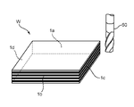
- FIG. 3 is a schematic perspective view explaining the outline of cutting of the outer peripheral surface (hereinafter sometimes referred to as "cutting").
- a work W is formed as shown in FIG. 3 by alternately stacking a plurality of pressure-sensitive adhesive layer-attached optical laminates and a plurality of intervening films. be done.
- the workpiece W has outer peripheral surfaces 1a and 1b facing each other and outer peripheral surfaces 1c and 1d orthogonal thereto.
- the workpiece W is preferably clamped from above and below by clamping means (not shown).
- the clamping means may be composed of a soft material or a hard material.
- its hardness JIS A is preferably 60° to 80°. If the hardness is too high, there may be impressions left by the clamping means. If the hardness is too low, the deformation of the jig may cause misalignment, resulting in insufficient cutting accuracy.
- the pressure-sensitive adhesive layer-attached optical layered body is cut into any appropriate shape when forming a work.
- the pressure-sensitive adhesive layer-attached optical layered body may be cut into a rectangular shape as in the illustrated example, and may have a shape similar to the rectangular shape (for example, a recess in the center of the long side when viewed from above). It may be cut into a shape-formed rectangular shape), or may be cut into an appropriate shape (for example, a circle) according to the purpose.
- End mill cutting can be performed by any suitable means. Specifically, the cutting may be so-called full-back machining, or may be end-mill machining as shown in FIG. End milling will be described below as a typical example of cutting. First, an end mill that can be used for cutting will be described.
- FIG. 4 is a schematic perspective view for explaining the structure of an end mill having helical blades.
- an end mill 60 having a helical edge has a rotating shaft 61 extending in the stacking direction (vertical direction) of the workpiece W, and a cutting blade having an outermost diameter of a main body that rotates about the rotating shaft 61. 62 and .
- the cutting edge 62 is configured as an outermost diameter that is twisted along the axis of rotation 61, exhibiting a right edge right helix.
- the cutting blade 62 includes a cutting edge 62a, a rake face 62b, and a relief face 62c.
- the number of cutting blades 62 can be appropriately set according to the purpose. In the illustrated example, there are three cutting blades, but the number of blades may be one, two, four, or five or more. good.
- the blade angle of the end mill (helix angle ⁇ of the cutting blade in the illustrated example) is preferably 20° to 70°, more preferably 30° to 60°.
- the relief surface of the cutting edge is preferably roughened. Any appropriate treatment can be adopted as the roughening treatment. A typical example is blasting. By roughening the relief surface, adhesion of the adhesive to the cutting blade is suppressed, and as a result, blocking can be suppressed.
- the outer diameter of the end mill is preferably 5 mm to 20 mm, more preferably 10 mm to 20 mm.
- the term “blocking” refers to a phenomenon in which optical laminates with an adhesive layer adhere to each other with the adhesive on the end surfaces of a work, and the shavings of the adhesive adhered to the end surfaces are the optical laminate with an adhesive layer. It contributes to adhesion between bodies.
- the "outer diameter of the end mill” refers to the distance from the rotating shaft 61 to the cutting edge 62a doubled.
- the end mill may be a cantilever end mill with one end (upper end) held, or a double end mill with both ends (upper end and lower end) held.
- the pocket area per edge of the end mill having a helical edge is preferably 5 mm 2 or more, more preferably 10 mm 2 or more, more preferably 11 mm 2 to 40 mm 2 .
- the pocket ratio per edge of an end mill having a helical edge is preferably 35% to 55%, more preferably 38% to 52%, and still more preferably 42% to 50%. If the pocket area and pocket ratio per blade are within these ranges, the lifting of the release liner can be suppressed satisfactorily.
- the pocket area is the area of an imaginary circle (circle indicated by the dashed line in Fig. 5) whose diameter is the outer diameter of the end mill and the projected area of the end mill main body (Fig. 5 (solid line)).
- the pocket area per blade is obtained by dividing the pocket area by the number of blades.
- the pocket ratio is obtained by dividing the pocket area by the area of the virtual circle.
- the pocket area can be obtained by any suitable image processing. Although the pocket area depends on the outer diameter and the number of flutes of the end mill, in the embodiment of the present invention, the release liner is well suppressed by optimizing the pocket area regardless of the outer diameter and the number of flutes. can do.
- a torsion file may be used as an end mill.
- FIG. 6 is a schematic perspective view for explaining the structure of the torsion file.
- the twist file 70 is typically constructed by attaching diamond grains to an end mill having a twist edge, as shown in FIG.
- the torsion file 70 has a rotating shaft 71 extending in the stacking direction (vertical direction) of the works W, and a cutting edge 72 configured as the outermost diameter of the main body that rotates about the rotating shaft 71.
- Diamond particles are attached to the cutting edge 72 and a file portion 73 is formed.
- the cutting edge 72 is configured as an outermost diameter that is twisted along the axis of rotation 71, exhibiting a right edge right helix.
- the cutting blade 72 includes a cutting edge 72a, a rake face 72b, and a relief face 72c.
- the number of cutting blades 72 can be appropriately set according to the purpose. In the illustrated example, there are three cutting blades, but the number of blades may be one, two, four, or five or more. good.
- the twist angle ⁇ is preferably 10° to 70°, more preferably 30° to 60°.
- the rake angle is preferably 1° to 25°, more preferably 3° to 20°, still more preferably 3° to 10°. In one embodiment, as shown in FIG. 7, the helix rasp 70 (substantially the cutting edge 72) has no clearance angle.
- the cutting edge 72a has a flat surface, and a state in which the cutting edge 72a and the surface to be machined (cut) of the workpiece are in contact with each other can be realized.
- the width B of the flat surface of the cutting edge 72a is preferably 0.1 mm or more, more preferably 0.2 mm to 1.4 mm, even more preferably 0.4 mm to 1.0 mm. If the width is too small, the crack suppression effect may be insufficient. If the width is too large, it becomes substantially the same as a bar file, and the effect as a torsion file may not be obtained.
- FIG. 7 is a schematic diagram for easy viewing, and does not correspond to the torsion file in FIG.
- Machining with a torsion file may be performed by "normal machining” in which the rake face 72b is on the upstream side in the rotational direction, or by “mineuchi machining” in which the relief face 72c side (the back side of the blade) is on the upstream side in the rotational direction. you can go In the case of “Mineuchi Machining”, even if there is a clearance angle (when the width B of the flat surface of the cutting edge 72a is 0: the clearance angle can be, for example, 2 to 25°), the cutting edge 72a and the workpiece are covered. Since the machined (cut) surface is in contact with the surface, a sufficient crack suppression effect can be obtained even when the clearance angle is provided.
- Mineuchi processing can be realized, for example, by reversing the rotation direction of the twist file, or by setting the rotation direction of the twist file to be the same as in the case of normal processing, and by reversing the mounting direction from that in the case of normal processing.
- FIG. 8 is a schematic cross-sectional view of a main part for explaining the uneven shape of the file portion 73.
- the depth D of the unevenness of the file portion 73 is, for example, 5 ⁇ m to 120 ⁇ m.
- the lower limit of the depth D is preferably 8 ⁇ m or more, more preferably 15 ⁇ m or more.
- the upper limit of the depth D is preferably 50 ⁇ m or less, more preferably 35 ⁇ m or less.
- the unevenness pitch P of the file portion 73 is, for example, 5 ⁇ m to 250 ⁇ m.
- the lower limit of the pitch P is preferably 10 ⁇ m or more, more preferably 25 ⁇ m or more.
- the upper limit of the pitch P is preferably 100 ⁇ m or less, more preferably 60 ⁇ m or less.
- the diameter (outer diameter) of the twist file 70 (substantially the cutting edge 72) can be, for example, 2 mm to 12 mm.
- the length L of the file portion 73 can be, for example, 10 mm to 100 mm.
- the "torsion file diameter” means the distance from the rotating shaft 71 to the cutting edge 72a doubled, similarly to the above-mentioned "end mill diameter”.
- the arithmetic mean height (Sa) of the surface of the file portion 73 is preferably 1 ⁇ m to 15 ⁇ m, more preferably 3 ⁇ m to 10 ⁇ m.
- the maximum height (Sz) of the surface of the file portion 73 is preferably 10 ⁇ m to 100 ⁇ m, more preferably 25 ⁇ m to 80 ⁇ m.
- These surface roughnesses can be measured according to the ISO 25178 "non-contact type (optical probe)" evaluation method. Specifically, it can be measured with a laser microscope (manufactured by Keyence Corporation, product name “VK-X1000”). Further, the particle size of diamond particles is, for example, 1 ⁇ m to 100 ⁇ m.
- the number of the file portion of the twist file may be, for example, #100 or higher, preferably #200 or higher, and more preferably #500 or higher.
- the file number may be, for example, #3000 or less, preferably #2500 or less, and more preferably #2200 or less.
- the count can be adjusted by adjusting the size of the diamond particles.
- Cutting may be performed only once, or may be performed multiple times (for example, twice, three times, four times or more).
- cutting is performed only once.
- cutting is typically performed using an end mill having a helical edge.
- the cutting is done twice.
- the cutting preferably includes rough cutting with an end mill having a helical edge and finish cutting with a helical file.
- the term "paste ball” refers to an adhesive forming an adhesive layer protruding from an end face during cutting, and the protruding adhesive solidifying into granules.
- the amount cut by finish cutting is typically significantly smaller than the amount cut by rough cutting. With such a configuration, it is possible to maintain the dimensional accuracy of the obtained optical layered body with an adhesive layer, and to maintain excellent quality (for example, suppression of lifting and delamination).
- the cutting amount by rough cutting is preferably about 0.1 mm to 0.5 mm; the cutting amount by finish cutting is preferably about 0.01 mm to 0.05 mm.
- the conditions for cutting can be appropriately set according to the purpose and mode of cutting.
- the following cutting conditions may be employed.
- the number of revolutions of an end mill having a helical edge in rough cutting can vary according to the outer diameter of the end mill. For example, if the outer diameter is 15 mm, the rotation speed is preferably 5000 rpm to 15000 rpm, more preferably 8000 rpm to 10000 rpm; for example, if the outer diameter is 6 mm, the rotation speed is preferably 1000 rpm. 40000 rpm, more preferably 15000 rpm to 25000 rpm.
- the peripheral speed of the end mill having a helical edge in rough cutting (independent of the outer diameter) is preferably 200000 mm/min to 750000 mm/min, more preferably 250000 mm/min to 500000 mm/min.
- the feed speed of the end mill having a helical edge in rough cutting is preferably 500 mm/min to 2500 mm/min, more preferably 1000 mm/min to 2000 mm/min.
- the number of cuts at the cut location in one rough cut may be one cut, two cuts, three cuts or more.
- the number of rotations of the twist file in the finish cut can vary according to the outer diameter of the twist file.
- the rotation speed is preferably 2000 rpm to 6000 rpm, more preferably 3000 rpm to 4000 rpm; for example, if the outer diameter is 6 mm, the rotation speed is preferably 5000 rpm. ⁇ 15000 rpm, more preferably 7000 rpm ⁇ 10000 rpm.
- the peripheral speed of the twist file (independent of the outer diameter) in finish cutting is preferably 95000 mm/min to 300000 mm/min, more preferably 150000 mm/min to 200000 mm/min.
- the feed rate of the twist file in finish cutting is preferably 300 mm/min to 2000 mm/min, more preferably 500 mm/min to 1000 mm/min.
- the number of cuts at the cut location in one finish cut may be one cut, two cuts, three cuts or more.
- Thickness A thickness of 10 ⁇ m or less was measured using an interferometric film thickness meter (manufactured by Otsuka Electronics Co., Ltd., product name “MCPD-3000”). A thickness exceeding 10 ⁇ m was measured using a digital micrometer (manufactured by Anritsu Co., Ltd., product name “KC-351C”).
- Lifting of release liner A predetermined number of pressure-sensitive adhesive layer-attached optical layered bodies after cutting were extracted from the workpiece, and the entire circumference of each pressure-sensitive adhesive layer-attached optical layered body was observed using a magnifying glass or a microscope.
- the maximum floating amount among the floating amounts of the first release liner and the second release liner in the predetermined number of pressure-sensitive adhesive layer-attached optical laminates was defined as "release liner lift" and evaluated according to the following criteria.
- Example 1 Production of optical laminate with pressure-sensitive adhesive layer
- PVA polyvinyl alcohol
- a long optical function film (HC-TAC film) was attached to one side of this polarizer so that the longitudinal directions of the films were aligned.
- the HC-TAC film is a film in which a hard coat (HC) layer (2 ⁇ m) is formed on a triacetyl cellulose (TAC) film (25 ⁇ m), and the TAC film is attached to the polarizer side.
- a laminate of HC layer/protective layer (TAC film)/polarizer was obtained.
- a normal acrylic pressure-sensitive adhesive (thickness: 5 ⁇ m) was used.
- an ordinary acrylic pressure-sensitive adhesive (thickness: 5 ⁇ m) was used in the same manner as described above.
- HC layer/protective layer (TAC film)/polarizer/retardation layer was obtained.
- a first pressure-sensitive adhesive layer (storage modulus: 1.2 ⁇ 10 5 Pa, thickness: 500 ⁇ m) was formed on the HC layer surface of the obtained laminate, and a first release liner was applied to the first pressure-sensitive adhesive layer. I wore temporary clothes.
- a second adhesive layer (storage elastic modulus: 1.25 ⁇ 10 11 Pa, thickness: 20 ⁇ m) is formed on the surface of the retardation layer of the laminate, and a second release liner is formed on the second adhesive layer. was disguised as Thus, an optical laminate with an adhesive layer was produced.
- the pressure-sensitive adhesive layer-attached optical layered body obtained as described above was punched into a rectangle of 330 mm x 140 mm. At this time, the polarizer was punched so that the absorption axis direction of the polarizer was aligned with the short side direction. On the other hand, a PET film having a thickness of 350 ⁇ m and having the same size as the punched optical layered body with an adhesive layer was prepared and used as an intervening film. A workpiece (thickness of 5 mm or more) was formed by alternately stacking the punched optical layered body with the pressure-sensitive adhesive layer and the intervening film.
- the pressure-sensitive adhesive layer-attached optical layered body and the intervening film are arranged so that the upper and lower outermost layers of the workpiece are intervening films (that is, the number of intervening films is one more than the pressure-sensitive adhesive layer-attached optical layered body). repeated.
- the entire outer peripheral end face of the obtained work was cut with an end mill.
- the end mill had a helix angle of 50°, a rake angle of 5° and a relief angle of 15°.
- the outer diameter of the end mill is 8 mm
- the number of blades is 4, the area of a virtual circle whose diameter is the outer diameter (hereinafter referred to as “cross-sectional area” for convenience) is 50.2 mm 2 , and the cross-sectional area per blade is 12.6 mm 2 , the pocket area per blade was 6.4 mm 2 , and the pocket ratio per blade was 50.7%.
- the rotation speed of the end mill was 15000 rpm (peripheral speed: 380000 mm/min) and the feed rate was 1500 mm/min.
- the pressure-sensitive adhesive layer-attached optical layered body thus cut was subjected to the evaluation of (2) above. Table 1 shows the results.
- Paste balls When the workpiece (substantially, the adhesive layer-attached optical layered body) after cutting with an end mill was visually observed, glue balls were observed. This work was further subjected to cutting with a twist file.
- the diameter of the helix file was 6 mm, the number of blades was 4, the helix angle was 45°, the rake angle was 5°, there was no relief angle, the width of the flat surface of the cutting edge was 0.6 mm, and the number of the file was #1000. .
- the rotational speed of the twist file was 8000 rpm (peripheral speed: 150000 mm/min) and the feed rate was 900 mm/min.
- the paste When the workpiece (substantially, the pressure-sensitive adhesive layer-attached optical layered product) after cutting with a twist file was visually observed, the paste was removed to the extent that it could not be recognized.
- Example 2 A workpiece (substantially, an adhesive layer optical laminate) was cut with an end mill. Table 1 shows the results.
- Example 1 A workpiece was formed in the same manner as in Example 1, except that no intervening film was used, that is, only the pressure-sensitive adhesive layer-attached optical layered body was stacked. This workpiece was cut with an end mill in the same manner as in Example 2. Table 1 shows the results. As shown in Table 1, this comparative example exhibited poor floating, so cutting (evaluation of glue balls) using a twist file was not performed.
- the pressure-sensitive adhesive layer-carrying optical layered body obtained by the manufacturing method according to the embodiment of the present invention can be suitably used for image display devices.
Landscapes
- Engineering & Computer Science (AREA)
- Mechanical Engineering (AREA)
- Physics & Mathematics (AREA)
- General Physics & Mathematics (AREA)
- Optics & Photonics (AREA)
- Polarising Elements (AREA)
- Milling Processes (AREA)
- Adhesives Or Adhesive Processes (AREA)
- Grinding Of Cylindrical And Plane Surfaces (AREA)
- Polishing Bodies And Polishing Tools (AREA)
- Laminated Bodies (AREA)
Priority Applications (2)
| Application Number | Priority Date | Filing Date | Title |
|---|---|---|---|
| KR1020247001389A KR20240072120A (ko) | 2021-09-21 | 2022-06-23 | 점착제층 부착 광학 적층체의 제조 방법 |
| CN202280063709.9A CN117980099A (zh) | 2021-09-21 | 2022-06-23 | 附粘合剂层的光学层叠体的制造方法 |
Applications Claiming Priority (2)
| Application Number | Priority Date | Filing Date | Title |
|---|---|---|---|
| JP2021-153158 | 2021-09-21 | ||
| JP2021153158A JP7312221B2 (ja) | 2021-09-21 | 2021-09-21 | 粘着剤層付光学積層体の製造方法 |
Publications (1)
| Publication Number | Publication Date |
|---|---|
| WO2023047731A1 true WO2023047731A1 (ja) | 2023-03-30 |
Family
ID=85720444
Family Applications (1)
| Application Number | Title | Priority Date | Filing Date |
|---|---|---|---|
| PCT/JP2022/025075 Ceased WO2023047731A1 (ja) | 2021-09-21 | 2022-06-23 | 粘着剤層付光学積層体の製造方法 |
Country Status (5)
| Country | Link |
|---|---|
| JP (2) | JP7312221B2 (https=) |
| KR (1) | KR20240072120A (https=) |
| CN (1) | CN117980099A (https=) |
| TW (1) | TW202332532A (https=) |
| WO (1) | WO2023047731A1 (https=) |
Citations (3)
| Publication number | Priority date | Publication date | Assignee | Title |
|---|---|---|---|---|
| JP2008200817A (ja) * | 2007-02-21 | 2008-09-04 | Mitsubishi Materials Corp | エンドミル |
| WO2019070033A1 (ja) * | 2017-10-05 | 2019-04-11 | 住友化学株式会社 | 光学部材の製造方法及び製造装置 |
| JP2020134708A (ja) * | 2019-02-20 | 2020-08-31 | 日東電工株式会社 | 切削加工された粘着剤層付光学積層体の製造方法 |
Family Cites Families (5)
| Publication number | Priority date | Publication date | Assignee | Title |
|---|---|---|---|---|
| JP3483505B2 (ja) | 1999-08-11 | 2004-01-06 | 住友化学工業株式会社 | 積層フィルムの周縁の仕上げ方法 |
| JP2002273614A (ja) | 2002-03-13 | 2002-09-25 | Allied Material Corp | ダイヤモンドコーティングエンドミル |
| JP2004001115A (ja) | 2002-05-31 | 2004-01-08 | Nachi Fujikoshi Corp | ダイヤモンド被覆エンドミル |
| EP3213869B1 (en) | 2014-12-12 | 2019-08-21 | Mitsubishi Heavy Industries Machine Tool Co., Ltd. | Grinding tool and manufacturing method therefor |
| JP6997844B2 (ja) | 2019-11-14 | 2022-01-18 | 住友化学株式会社 | 積層体を加工する方法、加工フィルムの製造方法、および、積層体加工装置 |
-
2021
- 2021-09-21 JP JP2021153158A patent/JP7312221B2/ja active Active
-
2022
- 2022-06-23 CN CN202280063709.9A patent/CN117980099A/zh active Pending
- 2022-06-23 KR KR1020247001389A patent/KR20240072120A/ko active Pending
- 2022-06-23 WO PCT/JP2022/025075 patent/WO2023047731A1/ja not_active Ceased
- 2022-07-25 TW TW111127795A patent/TW202332532A/zh unknown
-
2023
- 2023-04-04 JP JP2023060508A patent/JP7573061B2/ja active Active
Patent Citations (3)
| Publication number | Priority date | Publication date | Assignee | Title |
|---|---|---|---|---|
| JP2008200817A (ja) * | 2007-02-21 | 2008-09-04 | Mitsubishi Materials Corp | エンドミル |
| WO2019070033A1 (ja) * | 2017-10-05 | 2019-04-11 | 住友化学株式会社 | 光学部材の製造方法及び製造装置 |
| JP2020134708A (ja) * | 2019-02-20 | 2020-08-31 | 日東電工株式会社 | 切削加工された粘着剤層付光学積層体の製造方法 |
Also Published As
| Publication number | Publication date |
|---|---|
| TW202332532A (zh) | 2023-08-16 |
| JP7573061B2 (ja) | 2024-10-24 |
| JP7312221B2 (ja) | 2023-07-20 |
| CN117980099A (zh) | 2024-05-03 |
| JP2023090712A (ja) | 2023-06-29 |
| JP2023044997A (ja) | 2023-04-03 |
| KR20240072120A (ko) | 2024-05-23 |
Similar Documents
| Publication | Publication Date | Title |
|---|---|---|
| JP7378653B2 (ja) | 切削加工された粘着剤層付光学積層体の製造方法 | |
| JP7378654B2 (ja) | 切削加工された粘着剤層付光学積層体の製造方法 | |
| JP7018349B2 (ja) | 切削加工された粘着剤層付光学積層体の製造方法 | |
| JP7689928B2 (ja) | 光学積層体、カバーガラス付光学積層体、およびこれらの製造方法、ならびにカバーガラス付画像表示装置 | |
| JP7312221B2 (ja) | 粘着剤層付光学積層体の製造方法 | |
| JP7744116B2 (ja) | 光学フィルム切削用エンドミルおよび該エンドミルを用いた光学フィルムの製造方法 | |
| TWI798418B (zh) | 經切削加工之附硬塗層之光學積層體之製造方法 | |
| JP7574278B2 (ja) | 貫通穴を有する粘着剤層付光学積層体の製造方法 | |
| JP7758570B2 (ja) | 光学フィルム切削用エンドミルおよび該エンドミルを用いた光学フィルムの製造方法 | |
| JP7374297B2 (ja) | 貫通穴を有する粘着剤層付光学積層体の製造方法および該製造方法に用いられる貫通穴形成装置 | |
| JP2024061761A (ja) | 光学フィルム切削用エンドミルおよび該エンドミルを用いた光学フィルムの製造方法 |
Legal Events
| Date | Code | Title | Description |
|---|---|---|---|
| 121 | Ep: the epo has been informed by wipo that ep was designated in this application |
Ref document number: 22872488 Country of ref document: EP Kind code of ref document: A1 |
|
| WWE | Wipo information: entry into national phase |
Ref document number: 202280063709.9 Country of ref document: CN |
|
| NENP | Non-entry into the national phase |
Ref country code: DE |
|
| 122 | Ep: pct application non-entry in european phase |
Ref document number: 22872488 Country of ref document: EP Kind code of ref document: A1 |