WO2023047622A1 - 情報処理装置および情報処理方法 - Google Patents
情報処理装置および情報処理方法 Download PDFInfo
- Publication number
- WO2023047622A1 WO2023047622A1 PCT/JP2022/006344 JP2022006344W WO2023047622A1 WO 2023047622 A1 WO2023047622 A1 WO 2023047622A1 JP 2022006344 W JP2022006344 W JP 2022006344W WO 2023047622 A1 WO2023047622 A1 WO 2023047622A1
- Authority
- WO
- WIPO (PCT)
- Prior art keywords
- display
- phase
- information
- light distribution
- information processing
- Prior art date
- Legal status (The legal status is an assumption and is not a legal conclusion. Google has not performed a legal analysis and makes no representation as to the accuracy of the status listed.)
- Ceased
Links
Images











Classifications
-
- H—ELECTRICITY
- H04—ELECTRIC COMMUNICATION TECHNIQUE
- H04N—PICTORIAL COMMUNICATION, e.g. TELEVISION
- H04N13/00—Stereoscopic video systems; Multi-view video systems; Details thereof
- H04N13/30—Image reproducers
- H04N13/327—Calibration thereof
-
- G—PHYSICS
- G06—COMPUTING OR CALCULATING; COUNTING
- G06V—IMAGE OR VIDEO RECOGNITION OR UNDERSTANDING
- G06V10/00—Arrangements for image or video recognition or understanding
- G06V10/40—Extraction of image or video features
- G06V10/60—Extraction of image or video features relating to illumination properties, e.g. using a reflectance or lighting model
-
- H—ELECTRICITY
- H04—ELECTRIC COMMUNICATION TECHNIQUE
- H04N—PICTORIAL COMMUNICATION, e.g. TELEVISION
- H04N13/00—Stereoscopic video systems; Multi-view video systems; Details thereof
- H04N13/30—Image reproducers
- H04N13/302—Image reproducers for viewing without the aid of special glasses, i.e. using autostereoscopic displays
- H04N13/305—Image reproducers for viewing without the aid of special glasses, i.e. using autostereoscopic displays using lenticular lenses, e.g. arrangements of cylindrical lenses
-
- H—ELECTRICITY
- H04—ELECTRIC COMMUNICATION TECHNIQUE
- H04N—PICTORIAL COMMUNICATION, e.g. TELEVISION
- H04N13/00—Stereoscopic video systems; Multi-view video systems; Details thereof
- H04N13/30—Image reproducers
- H04N13/302—Image reproducers for viewing without the aid of special glasses, i.e. using autostereoscopic displays
- H04N13/31—Image reproducers for viewing without the aid of special glasses, i.e. using autostereoscopic displays using parallax barriers
-
- H—ELECTRICITY
- H04—ELECTRIC COMMUNICATION TECHNIQUE
- H04N—PICTORIAL COMMUNICATION, e.g. TELEVISION
- H04N13/00—Stereoscopic video systems; Multi-view video systems; Details thereof
- H04N13/30—Image reproducers
- H04N13/302—Image reproducers for viewing without the aid of special glasses, i.e. using autostereoscopic displays
- H04N13/317—Image reproducers for viewing without the aid of special glasses, i.e. using autostereoscopic displays using slanted parallax optics
-
- H—ELECTRICITY
- H04—ELECTRIC COMMUNICATION TECHNIQUE
- H04N—PICTORIAL COMMUNICATION, e.g. TELEVISION
- H04N17/00—Diagnosis, testing or measuring for television systems or their details
- H04N17/04—Diagnosis, testing or measuring for television systems or their details for receivers
Definitions
- the present disclosure relates to an information processing device and an information processing method.
- a light distribution member such as a lenticular lens or a parallax barrier arranged on a display device such as a liquid crystal panel imparts directivity to light rays emitted from pixels, thereby providing a viewer with stereoscopic display using parallax images.
- a display device such as a liquid crystal panel
- the conventional technology described above has room for further improvement in terms of helping to eliminate image quality deterioration in stereoscopic display.
- the light distribution member may have in-plane unevenness due to misalignment during manufacturing or misalignment due to thermal or mechanical stress during use, and errors may occur with respect to the desired light beam direction.
- the present disclosure proposes an information processing device and an information processing method that can contribute to eliminating image quality deterioration in stereoscopic display.
- an information processing apparatus provides a light distribution device arranged on the display unit for distributing light rays of an image displayed on the display unit to visually recognize a stereoscopic object.
- a captured image acquisition unit that acquires a captured image of a stereoscopic display including a member; an imaging position acquisition unit that acquires an imaging position when the captured image is acquired; and a captured image generated according to the imaging position included in the captured image a correction information output unit that outputs correction information for the stereoscopic display for correcting display unevenness of the stereoscopic display based on the obtained phase pattern change and the imaging position.
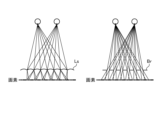
- FIG. 4 is a diagram showing the directivity of light rays by the lenticular lens method and the parallax barrier method;
- FIG. 4 is a diagram showing an example of a pixel array;
- FIG. 11 is a diagram (part 1) showing design values of a light distribution member;
- FIG. 10 is a diagram (part 2) showing design values of the light distribution member; It is a figure which shows the state of display unevenness.
- FIG. 10 is a diagram showing repetition of viewpoints by a light distribution member;
- FIG. 10 is a diagram showing distribution of viewpoints by a light distribution member; It is a figure which shows the difference of the observed brightness in a different observation position. It is a figure which shows the phase shift from the reference position of a light distribution member.
- FIG. 11 is a diagram (part 1) showing design values of a light distribution member
- FIG. 10 is a diagram (part 2) showing design values of the light distribution member; It is a figure which shows the state of display unevenness.
- FIG. 10 is
- FIG. 11 is a diagram (part 1) showing a method of calculating a phase shift amount;
- FIG. 11 is a diagram (part 2) showing a method of calculating a phase shift amount; It is a figure which shows the difference of the phase difference by a thickness error.
- FIG. It is a block diagram showing a configuration example of a measuring device according to a second embodiment of the present disclosure.
- FIG. 11 is a block diagram showing a configuration example of a measuring device according to a third embodiment of the present disclosure;
- FIG. It is supplementary explanatory drawing about the measuring device which concerns on each embodiment.
- FIG. 1 is a block diagram showing a configuration example of a video output device according to a first embodiment of the present disclosure
- FIG. FIG. 11 is a block diagram showing a configuration example of a video output device according to a second embodiment of the present disclosure
- FIG. FIG. 11 is a block diagram showing a configuration example of a video output device according to a third embodiment of the present disclosure
- FIG. 11 is an explanatory diagram (part 1) of a correction information output unit
- FIG. 11 is an explanatory diagram (part 2) of the correction information output unit
- It is a hardware block diagram which shows an example of the computer which implement
- an image display portion in which pixels such as a liquid crystal panel are arranged is appropriately referred to as a "display section”.
- FIG. 1 is a diagram showing the directivity of light rays by the lenticular lens method and the parallax barrier method.
- FIG. 2 is a diagram showing an example of a pixel array.
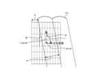
- FIG. 3 is a diagram (Part 1) showing the design values of the light distribution member.
- FIG. 4 is a diagram (part 2) showing design values of the light distribution member. 3 shows the positional relationship when the display section is viewed from the front, and FIG. 4 shows the positional relationship when the display section is viewed in cross section.
- FIG. 5 is a diagram showing the state of display unevenness.
- FIG. 6 is a diagram showing repetition of viewpoints by the light distribution member.
- FIG. 7 is a diagram showing distribution of viewpoints by the light distribution member.
- An information processing method includes a light distribution member arranged on a display unit, and stereoscopic vision in which directivity is imparted to light rays emitted from pixels of the display unit by the light distribution member.
- a fringe image is displayed on the display part while shifting the phase, luminance information of the interference fringes observed through the light distribution member is acquired, and phase information of the interference fringes is calculated using the acquired luminance information.
- a light distribution member such as a lenticular lens Ls or a parallax barrier Br is provided on a display section in which pixels are arranged
- light is emitted from the pixels through the lens of the lenticular lens Ls or the opening of the parallax barrier Br. Directivity is given to the light beam.
- the stereoscopic display shown in FIG. 1 is configured to present stereoscopic objects by providing different images directly to the left and right eyes of a viewer via the light distribution member.
- a stereoscopic display that provides a stereoscopic object without such a stereoscopic wearable optical device is generally called a light field display in some cases.
- the positional relationship between the pixels of the display unit and the light distribution member may deviate from the design value due to manufacturing errors such as molding errors in the light distribution member, misalignment during lamination of the display unit, and errors due to heat and mechanical stress during use.
- the ray direction is affected by the deviation.
- the display becomes uneven, so it is important to accurately measure the positional relationship during actual use in order to achieve comfortable stereoscopic display.
- x is the position of the pixel in the x direction of the display unit
- y is the position of the pixel in the y direction of the display unit
- A is the display brightness of the display
- o is the offset amount of the light distribution member
- d is the brightness noise at the time of observation.
- one cycle of the fringe is divided into N to display the phase-shifted cosine wave, and the cosine wave with the frequency f xs in the x direction and the frequency f ys in the y direction is displayed.
- the luminance distribution I of the interference fringes observed through the light distribution member arranged so as to sample is represented by the following equation (1).
- ⁇ can be obtained by the following equations (3) and (4) using a plurality of phase-shifted luminance distributions.
- the phase information of formula (5) indicates the light distribution state of light rays from each pixel given by the light distribution member, and means that the viewpoint is repeated at a 2 ⁇ cycle. Therefore, when 0 to 2 ⁇ are discretized to a certain number of viewpoints M, light rays from pixels corresponding to locations corresponding to each viewpoint position are spatially distributed.
- the viewer can visually recognize the display corresponding to each viewpoint.
- the viewpoints show rays of m to m+2 (1 ⁇ m ⁇ M ⁇ 2)th. Since the viewpoints are discretized and distributed, it is desirable that the intensity peak of the light ray is located between adjacent viewpoints for the same viewpoint.
- FIG. 8 is a diagram showing differences in observed brightness at different observation positions.
- FIG. 9 is a diagram showing the phase shift from the reference position of the light distribution member.
- FIG. 10 is a diagram (Part 1) showing a method of calculating the phase shift amount.
- FIG. 11 is a diagram (part 2) showing a method of calculating the phase shift amount.
- An information processing method in addition to the information processing method according to the first embodiment, measures the observation position, uses the phase shift amount corresponding to the measured position information, and displays the This is a method for adjusting the striped image to be displayed.
- the phase information of the light distribution member corresponding to the observation position is calculated. Therefore, as shown in FIG. 8, when the observation position moves, a different luminance distribution will be measured for each observation position, and the phase information will also differ for each observation position.
- the desired stereoscopic display can be performed only in the vicinity of that observation position. Therefore, in the second embodiment, in order to maintain accurate stereoscopic display regardless of the observation position, the positional relationship between the pixel position of the display unit and the light distribution member is obtained as phase information, and the phase shift corresponding to the observation position is calculated.
- ⁇ 1 is the angle when the position of the pixel of interest for which the phase shift amount is to be obtained is viewed from the observation position
- ⁇ 2 is the angle of light incident on the light distribution member
- d is the thickness of the light distribution member.
- the thickness is converted according to the fixed refractive index and thickness of each layer, and the addition is performed to obtain the formula (6) can be applied.
- the design parameters may be measured values.
- Addition or subtraction of the phase shift amount ⁇ obtained here is determined depending on the arrangement state of the light distribution member. As shown in FIG. 11, when the light distribution members are arranged at an inclination angle ⁇ , and the phase is calculated from 0 to 2 ⁇ from the left to the right in the front view in one cycle of the light distribution members in the x direction, ⁇ x is subtracted when a difference occurs in the left direction from the target pixel with respect to the phase of the cosine wave to be displayed, and is added when a difference occurs in the right direction.
- phase information of the light distribution member independent of the observation position can be obtained. be able to.
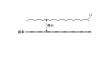
- FIG. 12 is a diagram showing a difference in phase difference due to thickness error.
- FIG. 13 is a diagram showing a phase difference caused by a thickness error.
- the information processing method according to the third embodiment of the present disclosure uses phase information of interference fringes or light distribution members acquired from two or more different observation positions, This is a method for measuring the thickness of a light distribution member.
- the thickness distribution of the light distribution member it is considered to obtain the thickness distribution of the light distribution member and use the obtained value to calculate an accurate phase shift amount.
- the actual thickness of the light distribution member (that is, the measured value of the thickness) can be obtained by calculating the phase information at two different points and comparing the phase difference with the difference in the calculated value of the phase shift amount.
- the phase shift amounts assumed at the first observation position and the second observation position are ⁇ d1 and ⁇ d2 .
- the phase information of the pixels observed at the actual thickness dr is measured. be done.
- the two items in parentheses in the denominator are determined to be addition or subtraction depending on the direction of the tilt angle ⁇ of the light distribution member, and are subtracted in the example similar to FIG. become.
- FIGS. 14 to 20 Information processing apparatus using information processing method according to each embodiment>>
- FIG. The measurement devices 10, 10A and 10B will be described with reference to FIGS. 14 to 17.
- FIG. Video output devices 30, 30A, and 30B will be described with reference to FIGS. 18 to 20.
- FIG. Each of the measuring devices 10, 10A, 10B and the video output devices 30, 30A, 30B corresponds to an example of "information processing device".
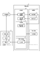
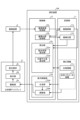
- FIG. 14 is a block diagram showing a configuration example of the measuring device 10 according to the first embodiment of the present disclosure. Note that FIG. 14 and FIGS. 15, 16, 18 to 20 shown later show only the constituent elements necessary for explaining the features of this embodiment, and omit the description of general constituent elements. .
- each component shown in FIGS. 14 to 16 and 18 to 20 is functionally conceptual and does not necessarily need to be physically configured as shown.
- the specific form of distribution/integration of each block is not limited to the one shown in the figure. It is possible to integrate and configure.
- the measurement apparatus 10 generates a fringe image in the display control unit based on the phase information calculated by the calculation unit, inputs it to the driving unit of the stereoscopic display, and displays the fringe image on the display unit.
- the observed interference fringe image is stored as a captured image in a storage unit, the captured image is input to a calculation unit, and the interference fringes and the phase information of the light distribution member are calculated. is.
- the measuring device 10 includes a storage unit 11 and a control unit 12.
- the imaging device 3 and the stereoscopic display 5 are connected to the measuring device 10 .
- the stereoscopic display 5 has a drive section 5a, a display section 5b, and a light distribution member 5c.
- the imaging device 3 captures a striped image displayed on the display unit 5b and through the light distribution member 5c.
- the imaging device 3 can be realized by, for example, a monocular camera, and the observation position in this case corresponds to the midpoint position of both eyes.
- the storage unit 11 is realized, for example, by semiconductor memory elements such as RAM (Random Access Memory), ROM (Read Only Memory), flash memory, or storage devices such as hard disks and optical disks.
- the storage unit 11 stores a captured image 11a, an imaging position 11b, and phase information 11c.
- the captured image 11 a is an image captured by the imaging device 3 .
- the imaging position 11b is the position where the captured image 11a is captured. In the first embodiment, the imaging position 11b is a specific position.
- the phase information 11c is information indicating the light distribution state of light from each pixel given by the light distribution member 5c, which is calculated by a calculation unit 12c described later.
- the phase information 11 c is included in correction information for correcting display unevenness of the stereoscopic display 5 .
- the control unit 12 is a controller. For example, various programs stored in the storage unit 11 are executed by a CPU (Central Processing Unit), MPU (Micro Processing Unit), etc., using RAM as a work area. It is realized by Also, the control unit 12 can be implemented by an integrated circuit such as an ASIC (Application Specific Integrated Circuit) or an FPGA (Field Programmable Gate Array).
- ASIC Application Specific Integrated Circuit
- FPGA Field Programmable Gate Array
- the control unit 12 includes a captured image acquisition unit 12a, an imaging position acquisition unit 12b, a calculation unit 12c, and a display control unit 12d, and implements or executes the information processing functions and actions described below.
- the captured image acquisition unit 12a acquires an image captured by the imaging device 3 and stores it as a captured image 11a.
- the imaging position acquisition unit 12b acquires the imaging position 11b.
- the calculator 12c includes a light distribution state calculator 12ca.
- the light distribution state calculator 12ca calculates the light distribution state of each pixel observed at the imaging position 11b based on the captured image 11a.
- the light distribution state calculator 12ca calculates the light distribution state using the calculation method in the information processing method according to the first embodiment described above. Further, the light distribution state calculator 12ca outputs the calculated light distribution state and stores it in the storage unit 11 as the phase information 11c.
- the display control unit 12d generates and outputs a display control signal for the stereoscopic display 5.
- the display control unit 12d includes a generation unit 12da.
- the generation unit 12da generates a stripe image while changing the stripe pattern, that is, the phase pattern, based on the phase information 11c, and outputs a display control signal for displaying the stripe image to the drive unit 5a.
- a series of movements by the captured image acquisition unit 12a, the imaging position acquisition unit 12b, the calculation unit 12c, and the display control unit 12d are repeatedly executed, and the phase information 11c can be updated at any time according to the result.
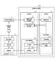
- FIG. 15 is a block diagram showing a configuration example of a measuring device 10A according to the second embodiment of the present disclosure. 15 corresponds to FIG. 14, only points different from the measuring apparatus 10 shown in FIG. 14 will be described here.
- the measurement device 10A measures the imaging position (observation position) and stores it in the storage unit 11, inputs the imaging position 11b to the calculation unit 12c, and outputs the calculated phase shift amount to the display control unit. 12d to adjust the fringe image.
- the measuring device 10A differs from the measuring device 10 in that the imaging position acquisition unit 12b calculates and acquires the imaging position 11b based on the captured image 11a.
- the measuring device 10A differs from the measuring device 10 in that the storage unit 11 further stores optical parameter information 11d.
- the optical parameter information 11d is information including the tilt angle, pitch, and thickness of the light distribution member 5c, and is included in the aforementioned correction information.
- the measuring device 10A is different from the measuring device 10 in that the calculator 12c further includes a phase shift amount calculator 12cb.
- the phase shift amount calculator 12cb calculates the phase shift amount based on the imaging position 11b and the optical parameter information 11d using the calculation method in the information processing method according to the second embodiment described above.
- the calculated phase shift amount is included in, for example, the phase information 11c and stored.
- the measurement device 10A differs from the measurement device 10 in that the display control section 12d further includes an adjustment section 12db.
- the adjustment unit 12db adjusts the fringe image generated by the generation unit 12da based on the phase shift amount calculated by the phase shift amount calculation unit 12cb.
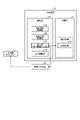
- FIG. 16 is a block diagram showing a configuration example of a measuring device 10B according to the third embodiment of the present disclosure.
- FIG. 16 corresponds to FIG. 15, only points different from the measuring apparatus 10A shown in FIG. 15 will be described here.
- the measurement device 10B stores the measurement position information and the calculation results of the interference fringes or the phase information of the light distribution member 5c at two or more different observation positions in the storage unit 11, and calculates the results. It is a device for inputting to the part 12c and calculating the thickness of the light distribution member 5c.
- the measuring device 10B differs from the measuring device 10A in that the storage unit 11 further stores thickness information 11e.
- the thickness information 11e is information including the actual thickness distribution of the light distribution member 5c (that is, the distribution of the measured values of the thickness), and is included in the aforementioned correction information.
- the measuring device 10B differs from the measuring device 10A in that the calculator 12c further includes a thickness calculator 12cc.
- the thickness calculator 12cc calculates the thickness distribution using the calculation method in the information processing method according to the above-described third embodiment based on the calculation results of the light distribution state calculator 12ca at two or more different imaging positions 11b.
- the calculated thickness distribution is stored as being included in the thickness information 11e.
- the measurement apparatus 10B calculates the phase shift amount using the thickness distribution calculated by the thickness calculation unit 12cc, and the adjustment unit 12db adjusts the fringe image in consideration of the thickness information 11e. Different from 10A.
- the functions of the measurement devices 10, 10A, and 10B may be separated from or integrated with the respective devices, and the stereoscopic display 5 may incorporate some or all of the functions of the measurement devices 10, 10A, and 10B. Alternatively, some or all of the functions of the measuring devices 10, 10A, and 10B may be incorporated into the imaging device 3.
- the measuring devices 10, 10A, and 10B can correct the optical parameter information 11d and the phase information 11c based on the measured phase information 11c.
- the tilt angle and pitch of the light distribution member 5c can be calculated using the phase difference between adjacent pixels of the phase information of the light distribution member 5c.
- the phase information 11c of the light distribution member 5c can be corrected by a method of correcting the phase information 11c of the light distribution member 5c, or by measuring the interference fringes obtained by adjusting the fringe image using the values of the optical parameters actually measured again. It is possible. That is, the optical parameter information 11d includes actual measurement values for design values.
- the phase information 11c of the light distribution member 5c can be corrected using the thickness distribution.
- the phase measurement by feeding back the calculation result of the phase information 11c to the generation of the fringe image, the distortion of the interference fringe image to be measured can be suppressed, and the accuracy of the phase calculation using the image can be improved. can be done. Therefore, by repeating the phase information measurement of the light distribution member 5c a plurality of times, the accuracy of the calculated phase information 11c can be improved.
- the observation position is calculated using a chessboard before the measurement of the interference fringes, and the fringe image is adjusted using that information. Since it is no longer necessary to update the position information for each measurement, it is possible to speed up the measurement.
- the position of the imaging device 3 may move for each photographing. There is a need to.
- FIG. 17 is a supplementary explanatory diagram of the measuring devices 10, 10A, and 10B according to each embodiment.
- the calibration pattern and the striped image are displayed in different display colors on the display unit 5b, the displayed image is obtained, color separation is performed by signal processing, and the respective colors are obtained.
- Position measurement and interference fringe phase measurement should be performed from the pattern.
- the observation position at the time of imaging is unknown at this time, it is not possible to adjust the fringe image according to the observation position.
- phase information 11c of the fringe image is obtained without adjustment, and then the phase information is adjusted by the phase shift amount estimated from the observation position, so that the light distribution member 5c that does not depend on the observation position It is possible to obtain the phase information 11c of
- FIG. 18 is a block diagram showing a configuration example of the video output device 30 according to the first embodiment of the present disclosure.
- the image output device 30 corrects the display unevenness of the stereoscopic display 5 based on the correction information output from the measuring device 10 using the information processing method according to the first embodiment described above. It is a device that controls the display of Note that the video output device 30 may be configured integrally with the stereoscopic display 5 .
- the video output device 30 includes a storage section 31 and a control section 32 . Also, the stereoscopic display 5 is connected to the video output device 30 .
- the storage unit 31 like the storage unit 11 described above, is realized by, for example, a semiconductor memory device such as a RAM, ROM, flash memory, or a storage device such as a hard disk or an optical disk. In the example shown in FIG. 18, the storage unit 31 stores viewing position 31a and phase information 31b.
- the viewing position 31a corresponds to the viewing position of the displayed image by the viewer.
- the viewing position 31a is a specific position.
- the phase information 31b is information corresponding to the phase information 11c that is calculated by the measuring device 10 and included in the output correction information, for example.
- the control unit 32 is a controller, similar to the storage unit 11 described above, and is realized by executing various programs stored in the storage unit 31 using the RAM as a work area, for example, by a CPU, an MPU, or the like.
- the control unit 32 can be realized by an integrated circuit such as an ASIC or FPGA, for example.
- the control unit 32 has a viewing position acquisition unit 32a and a display control unit 32c, and implements or executes the information processing functions and actions described below.
- the viewing position acquisition unit 32a acquires the viewing position 31a.
- the display control unit 32c generates and outputs a display control signal for the stereoscopic display 5.
- the display controller 32c includes a generator 32ca.
- the generation unit 32ca generates a display image while correcting display unevenness based on the phase information 31b, and outputs a display control signal for displaying the display image to the drive unit 5a.
- FIG. 19 is a block diagram showing a configuration example of a video output device 30A according to the second embodiment of the present disclosure. Note that FIG. 19 corresponds to FIG. 18, so only points different from the video output device 30 shown in FIG. 18 will be described here.
- the video output device 30A measures the viewing position (observation position) and stores it in the storage unit 31, calculates the phase shift amount based on the viewing position 31a, and calculates the phase shift amount. is input to the display control unit 12d to adjust the display image.
- the video output device 30A differs from the video output device 30 in that the position measuring device 7 is further connected.
- the position measuring device 7 measures the viewing position of viewing.
- a position measurement method a method of estimating the viewing position by detecting the viewer's face from a captured image, a method of detecting by three-dimensional measurement, and the like are conceivable.
- the video output device 30A differs from the video output device 30 in that the viewing position acquisition unit 32a acquires the viewing position 31a from the position measuring device 7.
- the video output device 30A differs from the video output device 30 in that the storage unit 31 further stores optical parameter information 31c.
- the optical parameter information 31c corresponds to the optical parameter information 11d included in the correction information output from the measuring device 10A.
- the video output device 30A differs from the video output device 30 in that the control unit 32 further includes a phase shift amount calculation unit 32b.
- the phase shift amount calculator 32b calculates the phase shift amount based on the viewing position 31a and the optical parameter information 31c using the calculation method in the information processing method according to the second embodiment described above.
- the video output device 30A differs from the video output device 30 in that the display control section 32c further includes an adjustment section 32cb.
- the adjuster 32cb adjusts the display image generated by the generator 32ca based on the phase shift amount calculated by the phase shift amount calculator 32b.
- FIG. 20 is a block diagram showing a configuration example of a video output device 30B according to the third embodiment of the present disclosure. Note that FIG. 20 corresponds to FIG. 19, so only points different from the video output device 30A shown in FIG. 19 will be described here.
- the video output device 30B differs from the video output device 30A in that the storage unit 31 further stores thickness information 31d.
- the thickness information 31d corresponds to the thickness information 11e included in the correction information output from the measuring device 10B.
- the phase shift amount calculation unit 32b further uses the thickness information 31d to calculate the phase shift amount, and the adjustment unit 32cb adjusts the display image based on the phase shift amount. It is different from the output device 30A.
- correction information output unit The “calculation unit” and “display control unit” of the information processing apparatus according to each embodiment described so far can be rephrased as a “correction information output unit” that outputs correction information for correcting display unevenness. . This point will be described with reference to FIGS. 21 and 22, taking the measuring apparatus 10 described above as an example.
- FIG. 21 is an explanatory diagram (part 1) of the correction information output unit.
- FIG. 22 is an explanatory diagram (part 2) of the correction information output unit.
- the measuring apparatus 10 has a calculation unit 12c.
- the calculation unit 12c is called a "correction information output unit” that outputs correction information for the stereoscopic display 5 including the calculated phase information 11c and others. be able to.
- the measurement device 10 outputs correction information for the stereoscopic display 5 to the storage unit 11 . Also, for example, the measurement device 10 outputs correction information for the stereoscopic display 5 to the video output device 30 .
- the form of output to the video output device 30 may be transmission via a network or delivery via a recording medium. Alternatively, it may be distributed via a cloud server or the like.
- the measuring apparatus 10 has a display control unit 12d.
- the display control unit 12d outputs correction information for the stereoscopic display 5 including the phase information 11c and others as a display control signal. can be referred to as a "correction information output unit".
- the correction information output by the "correction information output unit" includes, for example, the optical parameter information 11d and the thickness information 11e described above.
- the light distribution member 5c may of course be the parallax barrier Br shown in FIG. 1, or may be another member.
- each component of each device illustrated is functionally conceptual and does not necessarily need to be physically configured as illustrated.
- the specific form of distribution and integration of each device is not limited to the illustrated one, and all or part of them can be functionally or physically distributed and integrated in arbitrary units according to various loads and usage conditions. Can be integrated and configured.
- the video output device 30 may be configured integrally with the stereoscopic display 5 .
- FIG. 23 is a hardware configuration diagram showing an example of a computer 1000 that implements the functions of the measuring device 10.
- Computer 1000 has CPU 1100 , RAM 1200 , ROM 1300 , HDD (Hard Disk Drive) 1400 , communication interface 1500 and input/output interface 1600 .
- bus 1050 Each part of computer 1000 is connected by bus 1050 .
- the CPU 1100 operates based on programs stored in the ROM 1300 or HDD 1400 and controls each section. For example, the CPU 1100 loads programs stored in the ROM 1300 or HDD 1400 into the RAM 1200 and executes processes corresponding to various programs.
- the ROM 1300 stores a boot program such as BIOS (Basic Input Output System) executed by the CPU 1100 when the computer 1000 is started, and programs dependent on the hardware of the computer 1000.
- BIOS Basic Input Output System
- the HDD 1400 is a computer-readable recording medium that non-temporarily records programs executed by the CPU 1100 and data used by such programs.
- HDD 1400 is a recording medium that records an information processing program according to the present disclosure, which is an example of program data 1450 .
- a communication interface 1500 is an interface for connecting the computer 1000 to an external network 1550 (for example, the Internet).
- CPU 1100 receives data from another device via communication interface 1500, and transmits data generated by CPU 1100 to another device.
- the input/output interface 1600 is an interface for connecting the input/output device 1650 and the computer 1000 .
- the CPU 1100 receives data from input devices such as a keyboard and mouse via the input/output interface 1600 .
- the CPU 1100 also transmits data to an output device such as a display, speaker, or printer via the input/output interface 1600 .
- the input/output interface 1600 may function as a media interface for reading a program or the like recorded on a predetermined recording medium (media).
- Media include, for example, optical recording media such as DVD (Digital Versatile Disc) and PD (Phase change rewritable disk), magneto-optical recording media such as MO (Magneto-Optical disk), tape media, magnetic recording media, semiconductor memories, etc. is.
- the CPU 1100 of the computer 1000 implements the functions of the control section 12 by executing the information processing program loaded on the RAM 1200.
- the HDD 1400 also stores an information processing program according to the present disclosure and data in the storage unit 11 .
- CPU 1100 reads and executes program data 1450 from HDD 1400 , as another example, these programs may be obtained from another device via external network 1550 .
- the measurement devices 10, 10A, and 10B distribute the light rays of the image displayed on the display unit 5b to display the stereoscopic object on the display unit 5b.
- a captured image acquisition unit 12a that acquires a captured image of a stereoscopic display 5 having a light distribution member 5c arranged thereon; an imaging position acquisition unit 12b that acquires an imaging position when the captured image is acquired; a calculation unit 12c for outputting correction information for the stereoscopic display 5 for correcting display unevenness of the stereoscopic display 5 based on the change in the phase pattern generated according to the imaging position and the imaging position, or a display and a control unit 12d (corresponding to an example of a “correction information output unit”).
- This can contribute to elimination of image quality deterioration in stereoscopic display.
- a captured image acquisition unit that acquires a captured image of a stereoscopic display including a light distribution member arranged on the display unit for distributing light rays of an image displayed on the display unit and allowing a stereoscopic object to be viewed; an imaging position acquisition unit that acquires an imaging position at the time of acquisition of the captured image; Correction information for the stereoscopic display for correcting display unevenness of the stereoscopic display is output based on the change in the phase pattern generated according to the imaging position and the imaging position, which are included in the captured image. a correction information output unit; An information processing device.
- the correction information is a display control signal for controlling display of the stereoscopic display so as to correct display unevenness of the stereoscopic display.
- the information processing device according to (1) above.
- the correction information output unit is generating the display control signal based on phase information indicating the light distribution state of the light beam from each pixel of the display unit provided by the light distribution member based on the change in the phase pattern;
- the information processing device according to (2) above.
- the correction information output unit is generating the display control signal based on the phase information when the phase pattern is changed by displaying a fringe image on the display unit while shifting the phase;
- the information processing device according to (3) above.
- the correction information output unit is generating the display control signal based on the phase information when a cosine wave phase-shifted by dividing one period of fringes by 3 or more is displayed on the display unit;
- the information processing device according to (4) above.
- the phase information includes a positional relationship between a pixel position of the display unit and the light distribution member;
- the correction information output unit is generating the display control signal based on a phase shift amount from a predetermined reference position of the light distribution member according to the imaging position, which is calculated based on the phase information;
- the information processing device according to (3) above.
- the correction information output unit is generating the display control signal based on the phase shift amount based on the measured value of the thickness of the light distribution member calculated based on the comparison of the phase information at each of the different imaging positions;
- the correction information includes measured values for design values regarding the arrangement of the light distribution member, The information processing device according to (1) above.
- the measured value includes the measured value of the thickness of the light distribution member with respect to the display unit.
- the correction information output unit is Phase information including a light distribution state of light from each pixel of the display unit provided by the light distribution member is calculated based on the change in the phase pattern, and an actual measurement value of the thickness is calculated based on the phase information.
- the correction information output unit is calculating the luminance distribution of the interference fringes included in the captured image when the fringe image is displayed on the display unit while shifting the phase, and calculating the phase information based on the luminance distribution;
- the correction information output unit is calculating a measured value of the thickness based on a comparison of the phase information at each of the different imaging positions;
- the phase information includes a positional relationship between a pixel position of the display unit and the light distribution member;
- the correction information output unit is calculating a phase shift amount from a predetermined reference position of the light distribution member according to the imaging position based on the phase information, and adjusting the phase shift amount based on the measured value of the thickness;
- the information processing apparatus according to (10), (11) or (12).
- the light distribution member is a lenticular lens or a parallax barrier, The information processing apparatus according to any one of (1) to (13) above.
- the stereoscopic display is configured to present the stereoscopic object by directly providing different images to left and right eyes of a viewer via the light distribution member.
- the information processing device according to (14) above.
- a method of processing information comprising: (17) to the computer, Acquiring a captured image of a stereoscopic display including a light distribution member arranged on the display unit for distributing light rays of an image displayed on the display unit and allowing a stereoscopic object to be viewed; Acquiring an imaging position at the time of acquisition of the captured image; Correction information for the stereoscopic display for correcting display unevenness of the stereoscopic display is output based on the change in the phase pattern generated according to the imaging position and the imaging position, which are included in the captured image.
- imaging device 5 stereoscopic display 5a driving unit 5b display unit 5c light distribution member 10, 10A, 10B measuring device 12a captured image acquisition unit 12b imaging position acquisition unit 12c calculation unit 12d display control unit 30, 30A, 30B video output device 31a Viewing position 31b Phase information 31c Optical parameter information 31d Thickness information 32a Viewing position acquisition unit 32b Phase shift amount calculation unit 32c Display control unit Br Parallax barrier Ls Lenticular lens
Landscapes
- Engineering & Computer Science (AREA)
- Multimedia (AREA)
- Signal Processing (AREA)
- Physics & Mathematics (AREA)
- Software Systems (AREA)
- General Physics & Mathematics (AREA)
- Theoretical Computer Science (AREA)
- Health & Medical Sciences (AREA)
- Biomedical Technology (AREA)
- General Health & Medical Sciences (AREA)
- Optics & Photonics (AREA)
- Length Measuring Devices By Optical Means (AREA)
Priority Applications (2)
| Application Number | Priority Date | Filing Date | Title |
|---|---|---|---|
| US18/689,872 US20240397029A1 (en) | 2021-09-21 | 2022-02-17 | Information processing apparatus and information processing method |
| JP2023549329A JP7848807B2 (ja) | 2021-09-21 | 2022-02-17 | 情報処理装置および情報処理方法 |
Applications Claiming Priority (2)
| Application Number | Priority Date | Filing Date | Title |
|---|---|---|---|
| JP2021153530 | 2021-09-21 | ||
| JP2021-153530 | 2021-09-21 |
Publications (1)
| Publication Number | Publication Date |
|---|---|
| WO2023047622A1 true WO2023047622A1 (ja) | 2023-03-30 |
Family
ID=85720332
Family Applications (1)
| Application Number | Title | Priority Date | Filing Date |
|---|---|---|---|
| PCT/JP2022/006344 Ceased WO2023047622A1 (ja) | 2021-09-21 | 2022-02-17 | 情報処理装置および情報処理方法 |
Country Status (3)
| Country | Link |
|---|---|
| US (1) | US20240397029A1 (https=) |
| JP (1) | JP7848807B2 (https=) |
| WO (1) | WO2023047622A1 (https=) |
Citations (2)
| Publication number | Priority date | Publication date | Assignee | Title |
|---|---|---|---|---|
| JP2012060332A (ja) * | 2010-09-07 | 2012-03-22 | Iix Inc | 表示装置 |
| WO2021111786A1 (ja) * | 2019-12-04 | 2021-06-10 | ソニーグループ株式会社 | 調整装置、調整方法、および調整プログラム |
Family Cites Families (6)
| Publication number | Priority date | Publication date | Assignee | Title |
|---|---|---|---|---|
| JP2004212648A (ja) * | 2002-12-27 | 2004-07-29 | Olympus Corp | 映像表示装置及び映像表示方法 |
| JP4832833B2 (ja) * | 2005-09-01 | 2011-12-07 | 株式会社バンダイナムコゲームス | 配置レンズ諸元導出方法、プログラム、情報記憶媒体及び配置レンズ諸元導出装置 |
| JP5357688B2 (ja) * | 2009-10-01 | 2013-12-04 | 日本放送協会 | 基準映像表示装置の調整装置、撮像装置の調整装置および表示装置の調整装置 |
| JP2014066539A (ja) * | 2012-09-25 | 2014-04-17 | Jvc Kenwood Corp | 光学パラメータ測定装置、光学パラメータ測定方法、指向性表示装置 |
| WO2014167641A1 (ja) * | 2013-04-08 | 2014-10-16 | 株式会社イクス | 輝度測定方法、輝度測定装置及びこれらを用いた画質調整技術 |
| JP2024040528A (ja) * | 2021-01-19 | 2024-03-26 | ソニーグループ株式会社 | 情報処理装置、情報処理方法、及びプログラム |
-
2022
- 2022-02-17 US US18/689,872 patent/US20240397029A1/en active Pending
- 2022-02-17 WO PCT/JP2022/006344 patent/WO2023047622A1/ja not_active Ceased
- 2022-02-17 JP JP2023549329A patent/JP7848807B2/ja active Active
Patent Citations (2)
| Publication number | Priority date | Publication date | Assignee | Title |
|---|---|---|---|---|
| JP2012060332A (ja) * | 2010-09-07 | 2012-03-22 | Iix Inc | 表示装置 |
| WO2021111786A1 (ja) * | 2019-12-04 | 2021-06-10 | ソニーグループ株式会社 | 調整装置、調整方法、および調整プログラム |
Also Published As
| Publication number | Publication date |
|---|---|
| JPWO2023047622A1 (https=) | 2023-03-30 |
| JP7848807B2 (ja) | 2026-04-21 |
| US20240397029A1 (en) | 2024-11-28 |
Similar Documents
| Publication | Publication Date | Title |
|---|---|---|
| JP7016892B2 (ja) | 測定対象の表面を光学測定する方法及び装置 | |
| CN107121786B (zh) | 集成成像光场显示系统透镜阵列的校准方法 | |
| JP5016520B2 (ja) | 3次元形状計測方法および装置 | |
| JP5633058B1 (ja) | 3次元計測装置及び3次元計測方法 | |
| US20030035100A1 (en) | Automated lens calibration | |
| JP5881732B2 (ja) | 画像処理装置、立体画像表示装置、画像処理方法および画像処理プログラム | |
| KR20100015475A (ko) | 형상 측정 장치 및 형상 측정 방법 | |
| JPWO2011010438A1 (ja) | 視差検出装置、測距装置及び視差検出方法 | |
| US20150369589A1 (en) | Positional shift amount measurement method, correction table generation apparatus, imaging apparatus, and projecting apparatus | |
| JP4832833B2 (ja) | 配置レンズ諸元導出方法、プログラム、情報記憶媒体及び配置レンズ諸元導出装置 | |
| JP5313187B2 (ja) | 立体画像補正装置および立体画像補正方法 | |
| US10997455B2 (en) | Apparatus and method of correcting 3D image distortion | |
| JP2012085225A (ja) | 画質調整システム及び画質調整方法 | |
| US20250271327A1 (en) | Method and system for characterizing an optical lens for correcting optical aberrations introduced by said optical lens in an image | |
| JP5746046B2 (ja) | 特に歯科医療を目的とした物体表面の三次元測定方法 | |
| JP2020160383A (ja) | 映像補正装置、映像処理システム、表示装置、及び輝度ムラ補正方法 | |
| JP2013130529A (ja) | 検査装置、検査システム、検査方法、コンピュータを検査装置として機能させるためのプログラム、コンピュータを検査システムとして機能させるためのプログラム、当該プログラムを格納したコンピュータ読み取り可能な不揮発性のデータ記録媒体 | |
| US20190170502A1 (en) | Position designation device and position designation method | |
| WO2023047622A1 (ja) | 情報処理装置および情報処理方法 | |
| JP2011002401A (ja) | 輝度測定装置における補正係数算出方法および輝度測定装置 | |
| WO2020192218A1 (zh) | 一种应用于光学系统的角度测量方法及测量装置 | |
| US20190342530A1 (en) | Method for Automatically Producing an Optical Blend Mask | |
| WO2013008578A1 (en) | Image capturing apparatus, control method of image capturing apparatus, three-dimensional measurement apparatus, and storage medium | |
| Zhang et al. | Optical aberration analysis of light field displays: a calibration approach for enhanced performance | |
| JP6748563B2 (ja) | 立体映像測定装置及び立体映像測定方法 |
Legal Events
| Date | Code | Title | Description |
|---|---|---|---|
| 121 | Ep: the epo has been informed by wipo that ep was designated in this application |
Ref document number: 22872381 Country of ref document: EP Kind code of ref document: A1 |
|
| WWE | Wipo information: entry into national phase |
Ref document number: 2023549329 Country of ref document: JP |
|
| WWE | Wipo information: entry into national phase |
Ref document number: 18689872 Country of ref document: US |
|
| NENP | Non-entry into the national phase |
Ref country code: DE |
|
| 122 | Ep: pct application non-entry in european phase |
Ref document number: 22872381 Country of ref document: EP Kind code of ref document: A1 |