WO2023042760A1 - ステータの製造方法、ステータ、ティース及びヨーク - Google Patents
ステータの製造方法、ステータ、ティース及びヨーク Download PDFInfo
- Publication number
- WO2023042760A1 WO2023042760A1 PCT/JP2022/033863 JP2022033863W WO2023042760A1 WO 2023042760 A1 WO2023042760 A1 WO 2023042760A1 JP 2022033863 W JP2022033863 W JP 2022033863W WO 2023042760 A1 WO2023042760 A1 WO 2023042760A1
- Authority
- WO
- WIPO (PCT)
- Prior art keywords
- yoke
- teeth
- tooth
- stator according
- concave
- Prior art date
Links
- 238000004519 manufacturing process Methods 0.000 title claims abstract description 40
- 238000000034 method Methods 0.000 title claims abstract description 34
- 229920005989 resin Polymers 0.000 claims abstract description 118
- 239000011347 resin Substances 0.000 claims abstract description 118
- 239000011342 resin composition Substances 0.000 claims abstract description 63
- 238000000576 coating method Methods 0.000 claims description 78
- 239000011248 coating agent Substances 0.000 claims description 73
- 239000003822 epoxy resin Substances 0.000 claims description 48
- 229920000647 polyepoxide Polymers 0.000 claims description 48
- 238000004804 winding Methods 0.000 claims description 31
- 239000000945 filler Substances 0.000 claims description 29
- 230000008569 process Effects 0.000 claims description 23
- 230000002093 peripheral effect Effects 0.000 claims description 21
- 230000009477 glass transition Effects 0.000 claims description 11
- 239000000463 material Substances 0.000 abstract description 12
- LNEPOXFFQSENCJ-UHFFFAOYSA-N haloperidol Chemical compound C1CC(O)(C=2C=CC(Cl)=CC=2)CCN1CCCC(=O)C1=CC=C(F)C=C1 LNEPOXFFQSENCJ-UHFFFAOYSA-N 0.000 description 21
- 239000003795 chemical substances by application Substances 0.000 description 13
- 239000013034 phenoxy resin Substances 0.000 description 13
- 229920006287 phenoxy resin Polymers 0.000 description 13
- 229920001187 thermosetting polymer Polymers 0.000 description 12
- IISBACLAFKSPIT-UHFFFAOYSA-N bisphenol A Chemical compound C=1C=C(O)C=CC=1C(C)(C)C1=CC=C(O)C=C1 IISBACLAFKSPIT-UHFFFAOYSA-N 0.000 description 11
- 229920003986 novolac Polymers 0.000 description 11
- 239000007822 coupling agent Substances 0.000 description 10
- ISWSIDIOOBJBQZ-UHFFFAOYSA-N Phenol Chemical compound OC1=CC=CC=C1 ISWSIDIOOBJBQZ-UHFFFAOYSA-N 0.000 description 9
- 229910000831 Steel Inorganic materials 0.000 description 7
- 238000000465 moulding Methods 0.000 description 7
- 239000005011 phenolic resin Substances 0.000 description 7
- 239000010959 steel Substances 0.000 description 7
- UFWIBTONFRDIAS-UHFFFAOYSA-N Naphthalene Chemical compound C1=CC=CC2=CC=CC=C21 UFWIBTONFRDIAS-UHFFFAOYSA-N 0.000 description 6
- ZUOUZKKEUPVFJK-UHFFFAOYSA-N diphenyl Chemical compound C1=CC=CC=C1C1=CC=CC=C1 ZUOUZKKEUPVFJK-UHFFFAOYSA-N 0.000 description 5
- 238000009413 insulation Methods 0.000 description 5
- 238000010030 laminating Methods 0.000 description 5
- 239000003054 catalyst Substances 0.000 description 4
- 229910052751 metal Inorganic materials 0.000 description 4
- 239000002184 metal Substances 0.000 description 4
- 239000001993 wax Substances 0.000 description 4
- QTBSBXVTEAMEQO-UHFFFAOYSA-N Acetic acid Chemical compound CC(O)=O QTBSBXVTEAMEQO-UHFFFAOYSA-N 0.000 description 3
- 229930185605 Bisphenol Natural products 0.000 description 3
- ZMANZCXQSJIPKH-UHFFFAOYSA-N Triethylamine Chemical compound CCN(CC)CC ZMANZCXQSJIPKH-UHFFFAOYSA-N 0.000 description 3
- 239000004305 biphenyl Substances 0.000 description 3
- 235000010290 biphenyl Nutrition 0.000 description 3
- PXKLMJQFEQBVLD-UHFFFAOYSA-N bisphenol F Chemical compound C1=CC(O)=CC=C1CC1=CC=C(O)C=C1 PXKLMJQFEQBVLD-UHFFFAOYSA-N 0.000 description 3
- 239000010680 novolac-type phenolic resin Substances 0.000 description 3
- 239000011134 resol-type phenolic resin Substances 0.000 description 3
- KJCVRFUGPWSIIH-UHFFFAOYSA-N 1-naphthol Chemical compound C1=CC=C2C(O)=CC=CC2=C1 KJCVRFUGPWSIIH-UHFFFAOYSA-N 0.000 description 2
- QTWJRLJHJPIABL-UHFFFAOYSA-N 2-methylphenol;3-methylphenol;4-methylphenol Chemical compound CC1=CC=C(O)C=C1.CC1=CC=CC(O)=C1.CC1=CC=CC=C1O QTWJRLJHJPIABL-UHFFFAOYSA-N 0.000 description 2
- VPWNQTHUCYMVMZ-UHFFFAOYSA-N 4,4'-sulfonyldiphenol Chemical compound C1=CC(O)=CC=C1S(=O)(=O)C1=CC=C(O)C=C1 VPWNQTHUCYMVMZ-UHFFFAOYSA-N 0.000 description 2
- 229910052582 BN Inorganic materials 0.000 description 2
- PZNSFCLAULLKQX-UHFFFAOYSA-N Boron nitride Chemical compound N#B PZNSFCLAULLKQX-UHFFFAOYSA-N 0.000 description 2
- VYPSYNLAJGMNEJ-UHFFFAOYSA-N Silicium dioxide Chemical compound O=[Si]=O VYPSYNLAJGMNEJ-UHFFFAOYSA-N 0.000 description 2
- PNEYBMLMFCGWSK-UHFFFAOYSA-N aluminium oxide Inorganic materials [O-2].[O-2].[O-2].[Al+3].[Al+3] PNEYBMLMFCGWSK-UHFFFAOYSA-N 0.000 description 2
- WPYMKLBDIGXBTP-UHFFFAOYSA-N benzoic acid Chemical compound OC(=O)C1=CC=CC=C1 WPYMKLBDIGXBTP-UHFFFAOYSA-N 0.000 description 2
- 125000002529 biphenylenyl group Chemical group C1(=CC=CC=2C3=CC=CC=C3C12)* 0.000 description 2
- 239000004020 conductor Substances 0.000 description 2
- 229930003836 cresol Natural products 0.000 description 2
- 230000000694 effects Effects 0.000 description 2
- 238000005516 engineering process Methods 0.000 description 2
- -1 naphthylene ether Chemical compound 0.000 description 2
- WWZKQHOCKIZLMA-UHFFFAOYSA-N octanoic acid Chemical compound CCCCCCCC(O)=O WWZKQHOCKIZLMA-UHFFFAOYSA-N 0.000 description 2
- 150000002989 phenols Chemical class 0.000 description 2
- 125000000843 phenylene group Chemical group C1(=C(C=CC=C1)*)* 0.000 description 2
- 230000000704 physical effect Effects 0.000 description 2
- YGSDEFSMJLZEOE-UHFFFAOYSA-N salicylic acid Chemical compound OC(=O)C1=CC=CC=C1O YGSDEFSMJLZEOE-UHFFFAOYSA-N 0.000 description 2
- 150000003839 salts Chemical class 0.000 description 2
- RIOQSEWOXXDEQQ-UHFFFAOYSA-N triphenylphosphine Chemical compound C1=CC=CC=C1P(C=1C=CC=CC=1)C1=CC=CC=C1 RIOQSEWOXXDEQQ-UHFFFAOYSA-N 0.000 description 2
- HCNHNBLSNVSJTJ-UHFFFAOYSA-N 1,1-Bis(4-hydroxyphenyl)ethane Chemical compound C=1C=C(O)C=CC=1C(C)C1=CC=C(O)C=C1 HCNHNBLSNVSJTJ-UHFFFAOYSA-N 0.000 description 1
- QFMZQPDHXULLKC-UHFFFAOYSA-N 1,2-bis(diphenylphosphino)ethane Chemical compound C=1C=CC=CC=1P(C=1C=CC=CC=1)CCP(C=1C=CC=CC=1)C1=CC=CC=C1 QFMZQPDHXULLKC-UHFFFAOYSA-N 0.000 description 1
- XQUPVDVFXZDTLT-UHFFFAOYSA-N 1-[4-[[4-(2,5-dioxopyrrol-1-yl)phenyl]methyl]phenyl]pyrrole-2,5-dione Chemical compound O=C1C=CC(=O)N1C(C=C1)=CC=C1CC1=CC=C(N2C(C=CC2=O)=O)C=C1 XQUPVDVFXZDTLT-UHFFFAOYSA-N 0.000 description 1
- HECLRDQVFMWTQS-RGOKHQFPSA-N 1755-01-7 Chemical compound C1[C@H]2[C@@H]3CC=C[C@@H]3[C@@H]1C=C2 HECLRDQVFMWTQS-RGOKHQFPSA-N 0.000 description 1
- ZOQVDXYAPXAFRW-UHFFFAOYSA-N 2,5-diethyl-1h-imidazole Chemical compound CCC1=CNC(CC)=N1 ZOQVDXYAPXAFRW-UHFFFAOYSA-N 0.000 description 1
- CMLFRMDBDNHMRA-UHFFFAOYSA-N 2h-1,2-benzoxazine Chemical compound C1=CC=C2C=CNOC2=C1 CMLFRMDBDNHMRA-UHFFFAOYSA-N 0.000 description 1
- PVFQHGDIOXNKIC-UHFFFAOYSA-N 4-[2-[3-[2-(4-hydroxyphenyl)propan-2-yl]phenyl]propan-2-yl]phenol Chemical compound C=1C=CC(C(C)(C)C=2C=CC(O)=CC=2)=CC=1C(C)(C)C1=CC=C(O)C=C1 PVFQHGDIOXNKIC-UHFFFAOYSA-N 0.000 description 1
- ZRSCAJHLPIPKBU-UHFFFAOYSA-N 5-methyl-2-phenyl-1h-imidazol-4-ol Chemical compound N1C(O)=C(C)N=C1C1=CC=CC=C1 ZRSCAJHLPIPKBU-UHFFFAOYSA-N 0.000 description 1
- TYOXIFXYEIILLY-UHFFFAOYSA-N 5-methyl-2-phenyl-1h-imidazole Chemical compound N1C(C)=CN=C1C1=CC=CC=C1 TYOXIFXYEIILLY-UHFFFAOYSA-N 0.000 description 1
- ULKLGIFJWFIQFF-UHFFFAOYSA-N 5K8XI641G3 Chemical compound CCC1=NC=C(C)N1 ULKLGIFJWFIQFF-UHFFFAOYSA-N 0.000 description 1
- 239000004925 Acrylic resin Substances 0.000 description 1
- 229920000178 Acrylic resin Polymers 0.000 description 1
- 229910000838 Al alloy Inorganic materials 0.000 description 1
- 239000005711 Benzoic acid Substances 0.000 description 1
- GIXXQTYGFOHYPT-UHFFFAOYSA-N Bisphenol P Chemical compound C=1C=C(C(C)(C)C=2C=CC(O)=CC=2)C=CC=1C(C)(C)C1=CC=C(O)C=C1 GIXXQTYGFOHYPT-UHFFFAOYSA-N 0.000 description 1
- SDDLEVPIDBLVHC-UHFFFAOYSA-N Bisphenol Z Chemical compound C1=CC(O)=CC=C1C1(C=2C=CC(O)=CC=2)CCCCC1 SDDLEVPIDBLVHC-UHFFFAOYSA-N 0.000 description 1
- RYGMFSIKBFXOCR-UHFFFAOYSA-N Copper Chemical compound [Cu] RYGMFSIKBFXOCR-UHFFFAOYSA-N 0.000 description 1
- 229920000877 Melamine resin Polymers 0.000 description 1
- BGPVFRJUHWVFKM-UHFFFAOYSA-N N1=C2C=CC=CC2=[N+]([O-])C1(CC1)CCC21N=C1C=CC=CC1=[N+]2[O-] Chemical compound N1=C2C=CC=CC2=[N+]([O-])C1(CC1)CCC21N=C1C=CC=CC1=[N+]2[O-] BGPVFRJUHWVFKM-UHFFFAOYSA-N 0.000 description 1
- IGFHQQFPSIBGKE-UHFFFAOYSA-N Nonylphenol Natural products CCCCCCCCCC1=CC=C(O)C=C1 IGFHQQFPSIBGKE-UHFFFAOYSA-N 0.000 description 1
- 229920003171 Poly (ethylene oxide) Polymers 0.000 description 1
- 239000006087 Silane Coupling Agent Substances 0.000 description 1
- ATJFFYVFTNAWJD-UHFFFAOYSA-N Tin Chemical compound [Sn] ATJFFYVFTNAWJD-UHFFFAOYSA-N 0.000 description 1
- RTAQQCXQSZGOHL-UHFFFAOYSA-N Titanium Chemical compound [Ti] RTAQQCXQSZGOHL-UHFFFAOYSA-N 0.000 description 1
- UUQQGGWZVKUCBD-UHFFFAOYSA-N [4-(hydroxymethyl)-2-phenyl-1h-imidazol-5-yl]methanol Chemical compound N1C(CO)=C(CO)N=C1C1=CC=CC=C1 UUQQGGWZVKUCBD-UHFFFAOYSA-N 0.000 description 1
- 125000005577 anthracene group Chemical group 0.000 description 1
- 239000003963 antioxidant agent Substances 0.000 description 1
- 230000003078 antioxidant effect Effects 0.000 description 1
- 125000003710 aryl alkyl group Chemical group 0.000 description 1
- 230000004323 axial length Effects 0.000 description 1
- 235000010233 benzoic acid Nutrition 0.000 description 1
- 239000004203 carnauba wax Substances 0.000 description 1
- 235000013869 carnauba wax Nutrition 0.000 description 1
- 238000005266 casting Methods 0.000 description 1
- 125000002091 cationic group Chemical group 0.000 description 1
- 229910017052 cobalt Inorganic materials 0.000 description 1
- 239000010941 cobalt Substances 0.000 description 1
- GUTLYIVDDKVIGB-UHFFFAOYSA-N cobalt atom Chemical compound [Co] GUTLYIVDDKVIGB-UHFFFAOYSA-N 0.000 description 1
- XLJKHNWPARRRJB-UHFFFAOYSA-N cobalt(2+) Chemical compound [Co+2] XLJKHNWPARRRJB-UHFFFAOYSA-N 0.000 description 1
- JAWGVVJVYSANRY-UHFFFAOYSA-N cobalt(3+) Chemical compound [Co+3] JAWGVVJVYSANRY-UHFFFAOYSA-N 0.000 description 1
- 150000001875 compounds Chemical class 0.000 description 1
- 239000011231 conductive filler Substances 0.000 description 1
- 229910052802 copper Inorganic materials 0.000 description 1
- 239000010949 copper Substances 0.000 description 1
- PMHQVHHXPFUNSP-UHFFFAOYSA-M copper(1+);methylsulfanylmethane;bromide Chemical compound Br[Cu].CSC PMHQVHHXPFUNSP-UHFFFAOYSA-M 0.000 description 1
- XLJMAIOERFSOGZ-UHFFFAOYSA-M cyanate Chemical compound [O-]C#N XLJMAIOERFSOGZ-UHFFFAOYSA-M 0.000 description 1
- 230000003247 decreasing effect Effects 0.000 description 1
- 150000001993 dienes Chemical class 0.000 description 1
- 235000014113 dietary fatty acids Nutrition 0.000 description 1
- 238000010292 electrical insulation Methods 0.000 description 1
- RTZKZFJDLAIYFH-UHFFFAOYSA-N ether Substances CCOCC RTZKZFJDLAIYFH-UHFFFAOYSA-N 0.000 description 1
- 239000000194 fatty acid Substances 0.000 description 1
- 229930195729 fatty acid Natural products 0.000 description 1
- 150000004665 fatty acids Chemical class 0.000 description 1
- 230000004907 flux Effects 0.000 description 1
- 230000020169 heat generation Effects 0.000 description 1
- 125000004435 hydrogen atom Chemical group [H]* 0.000 description 1
- 230000001771 impaired effect Effects 0.000 description 1
- 239000004615 ingredient Substances 0.000 description 1
- 239000011256 inorganic filler Substances 0.000 description 1
- 229910003475 inorganic filler Inorganic materials 0.000 description 1
- 239000000203 mixture Substances 0.000 description 1
- 230000004048 modification Effects 0.000 description 1
- 238000012986 modification Methods 0.000 description 1
- 239000012778 molding material Substances 0.000 description 1
- 239000004206 montan acid ester Substances 0.000 description 1
- 235000013872 montan acid ester Nutrition 0.000 description 1
- GEMHFKXPOCTAIP-UHFFFAOYSA-N n,n-dimethyl-n'-phenylcarbamimidoyl chloride Chemical compound CN(C)C(Cl)=NC1=CC=CC=C1 GEMHFKXPOCTAIP-UHFFFAOYSA-N 0.000 description 1
- 125000001624 naphthyl group Chemical group 0.000 description 1
- SNQQPOLDUKLAAF-UHFFFAOYSA-N nonylphenol Chemical compound CCCCCCCCCC1=CC=CC=C1O SNQQPOLDUKLAAF-UHFFFAOYSA-N 0.000 description 1
- UTOPWMOLSKOLTQ-UHFFFAOYSA-N octacosanoic acid Chemical compound CCCCCCCCCCCCCCCCCCCCCCCCCCCC(O)=O UTOPWMOLSKOLTQ-UHFFFAOYSA-N 0.000 description 1
- 235000005985 organic acids Nutrition 0.000 description 1
- 150000002903 organophosphorus compounds Chemical class 0.000 description 1
- JOXIMZWYDAKGHI-UHFFFAOYSA-N p-toluenesulfonic acid Substances CC1=CC=C(S(O)(=O)=O)C=C1 JOXIMZWYDAKGHI-UHFFFAOYSA-N 0.000 description 1
- FJKROLUGYXJWQN-UHFFFAOYSA-N papa-hydroxy-benzoic acid Natural products OC(=O)C1=CC=C(O)C=C1 FJKROLUGYXJWQN-UHFFFAOYSA-N 0.000 description 1
- 239000012188 paraffin wax Substances 0.000 description 1
- 229920001568 phenolic resin Polymers 0.000 description 1
- RPGWZZNNEUHDAQ-UHFFFAOYSA-N phenylphosphine Chemical compound PC1=CC=CC=C1 RPGWZZNNEUHDAQ-UHFFFAOYSA-N 0.000 description 1
- 229920003192 poly(bis maleimide) Polymers 0.000 description 1
- 229920001721 polyimide Polymers 0.000 description 1
- 239000009719 polyimide resin Substances 0.000 description 1
- 229960004889 salicylic acid Drugs 0.000 description 1
- FZHAPNGMFPVSLP-UHFFFAOYSA-N silanamine Chemical compound [SiH3]N FZHAPNGMFPVSLP-UHFFFAOYSA-N 0.000 description 1
- HBMJWWWQQXIZIP-UHFFFAOYSA-N silicon carbide Chemical compound [Si+]#[C-] HBMJWWWQQXIZIP-UHFFFAOYSA-N 0.000 description 1
- 229910010271 silicon carbide Inorganic materials 0.000 description 1
- 239000000377 silicon dioxide Substances 0.000 description 1
- 229920002545 silicone oil Polymers 0.000 description 1
- 229920002050 silicone resin Polymers 0.000 description 1
- WSFQLUVWDKCYSW-UHFFFAOYSA-M sodium;2-hydroxy-3-morpholin-4-ylpropane-1-sulfonate Chemical compound [Na+].[O-]S(=O)(=O)CC(O)CN1CCOCC1 WSFQLUVWDKCYSW-UHFFFAOYSA-M 0.000 description 1
- 150000003512 tertiary amines Chemical class 0.000 description 1
- USFPINLPPFWTJW-UHFFFAOYSA-N tetraphenylphosphonium Chemical compound C1=CC=CC=C1[P+](C=1C=CC=CC=1)(C=1C=CC=CC=1)C1=CC=CC=C1 USFPINLPPFWTJW-UHFFFAOYSA-N 0.000 description 1
- QQOWHRYOXYEMTL-UHFFFAOYSA-N triazin-4-amine Chemical compound N=C1C=CN=NN1 QQOWHRYOXYEMTL-UHFFFAOYSA-N 0.000 description 1
- IMFACGCPASFAPR-UHFFFAOYSA-N tributylamine Chemical compound CCCCN(CCCC)CCCC IMFACGCPASFAPR-UHFFFAOYSA-N 0.000 description 1
- IMNIMPAHZVJRPE-UHFFFAOYSA-N triethylenediamine Chemical compound C1CN2CCN1CC2 IMNIMPAHZVJRPE-UHFFFAOYSA-N 0.000 description 1
- MXSVLWZRHLXFKH-UHFFFAOYSA-N triphenylborane Chemical compound C1=CC=CC=C1B(C=1C=CC=CC=1)C1=CC=CC=C1 MXSVLWZRHLXFKH-UHFFFAOYSA-N 0.000 description 1
- WXAZIUYTQHYBFW-UHFFFAOYSA-N tris(4-methylphenyl)phosphane Chemical compound C1=CC(C)=CC=C1P(C=1C=CC(C)=CC=1)C1=CC=C(C)C=C1 WXAZIUYTQHYBFW-UHFFFAOYSA-N 0.000 description 1
- 229920006337 unsaturated polyester resin Polymers 0.000 description 1
- 125000006839 xylylene group Chemical group 0.000 description 1
- XOOUIPVCVHRTMJ-UHFFFAOYSA-L zinc stearate Chemical compound [Zn+2].CCCCCCCCCCCCCCCCCC([O-])=O.CCCCCCCCCCCCCCCCCC([O-])=O XOOUIPVCVHRTMJ-UHFFFAOYSA-L 0.000 description 1
Images


Classifications
-
- H—ELECTRICITY
- H02—GENERATION; CONVERSION OR DISTRIBUTION OF ELECTRIC POWER
- H02K—DYNAMO-ELECTRIC MACHINES
- H02K1/00—Details of the magnetic circuit
- H02K1/06—Details of the magnetic circuit characterised by the shape, form or construction
- H02K1/12—Stationary parts of the magnetic circuit
- H02K1/18—Means for mounting or fastening magnetic stationary parts on to, or to, the stator structures
-
- H—ELECTRICITY
- H02—GENERATION; CONVERSION OR DISTRIBUTION OF ELECTRIC POWER
- H02K—DYNAMO-ELECTRIC MACHINES
- H02K15/00—Methods or apparatus specially adapted for manufacturing, assembling, maintaining or repairing of dynamo-electric machines
- H02K15/06—Embedding prefabricated windings in machines
-
- H—ELECTRICITY
- H02—GENERATION; CONVERSION OR DISTRIBUTION OF ELECTRIC POWER
- H02K—DYNAMO-ELECTRIC MACHINES
- H02K15/00—Methods or apparatus specially adapted for manufacturing, assembling, maintaining or repairing of dynamo-electric machines
- H02K15/10—Applying solid insulation to windings, stators or rotors
-
- H—ELECTRICITY
- H02—GENERATION; CONVERSION OR DISTRIBUTION OF ELECTRIC POWER
- H02K—DYNAMO-ELECTRIC MACHINES
- H02K3/00—Details of windings
- H02K3/32—Windings characterised by the shape, form or construction of the insulation
- H02K3/34—Windings characterised by the shape, form or construction of the insulation between conductors or between conductor and core, e.g. slot insulation
Definitions
- the present invention relates to a stator manufacturing method, stator, teeth and yoke.
- Patent Literature 1 discloses a technique for forming an insulating layer by injecting and hardening resin between a conductor (coil) and a peripheral wall portion of a slot.
- the present invention has been made in view of such circumstances, and aims to provide a technology that can improve the efficiency of manufacturing slots.
- a plurality of teeth which are provided separately from the yoke and wound with a coil, are provided on a cylindrical yoke so as to protrude toward the center in the radial direction from the cylindrical inner peripheral surface of the yoke. It has a tooth fixing process to be attached, A method for manufacturing a stator, wherein a region of the tooth around which the coil is wound is covered with a first cured product obtained by curing a first resin composition.
- the concave-convex fitting structure is a structure in which a yoke concave portion provided in a concave shape on the yoke and a tooth convex portion provided in a convex shape on the tooth are engaged. .
- the yoke recess is formed in a wedge shape with a radial center side narrowed
- the method of manufacturing a stator according to [7] wherein the teeth protrusions are formed in an inverted wedge shape that matches the wedge shape of the yoke recesses.
- the concave-convex fitting structure is a structure in which tooth concave portions provided in concave shapes on the teeth and yoke convex portions provided in convex shapes on the yoke are engaged. .
- the yoke convex portion is formed in a wedge shape with a radial center side widened, The manufacturing method of the stator according to [9], wherein the teeth recesses are formed in an inverted wedge shape that matches the wedge shape of the yoke protrusions.
- the glass transition temperature Tg of the first resin composition is 120° C. or higher.
- the stator according to [11] or [12], wherein the first resin composition contains an epoxy resin.
- the first resin composition contains a filler as a filler, The stator according to any one of [11] to [13].
- the stator according to [14], wherein the first resin composition has a filler content of 60% by volume or more.
- the stator according to any one of [11] to [15], wherein the first cured product has a thermal conductivity of 0.5 W/mK or more.
- the second resin composition has a glass transition temperature Tg of 120° C. or higher.
- the second resin composition contains a filler as a filler, The stator according to any one of [17] to [19].
- the stator according to [20], wherein the second resin composition has a filler content of 60% by volume or more.
- the concave-convex fitting structure is a structure in which a yoke concave portion provided in the yoke in a concave shape and a tooth convex portion provided in the tooth in a convex shape are engaged.
- the yoke recess is formed in a wedge shape with a radial center side narrowed
- the concave-convex fitting structure is a structure in which tooth concave portions provided in the teeth in a concave shape and yoke convex portions provided in the yoke in a convex shape are engaged.
- the yoke convex portion is formed in a wedge shape with a radial center side widened,
- FIG. 1 is a perspective view of a stator according to an embodiment
- FIG. It is a perspective view of a yoke according to the embodiment.
- FIG. 1 schematically shows a cross-sectional view of the motor 100 in a direction perpendicular to the rotating shaft direction.
- the outline of this embodiment is as follows.
- the stator 10 used in the motor 100 includes a cylindrical yoke 20, a plurality of teeth 30 provided separately from the yoke 20 and attached to the yoke 20, and around which coils 50 are wound. have The teeth 30 are attached to the cylindrical inner peripheral surface of the yoke 20 so as to protrude toward the center in the radial direction. Further, the teeth 30 are covered with the first cured product obtained by curing the first resin composition in the region around which the coil 50 is wound (the teeth resin coating portion 37 of the teeth base portion 31). That is, the yoke 20 and the teeth 30 are provided separately, and the stator 10 is obtained by assembling them.
- the present embodiment is mainly characterized by the structures of the stator 10, the yoke 20 and the teeth 30 and the manufacturing method of the stator 10. FIG. Therefore, in the following description, attention will be paid to them, and detailed description of general features of the components of the motor 100 will be omitted as appropriate.
- the motor 100 includes a case 1, and a rotor 2, a stator 10, and a coil 50 housed inside the case 1.
- the case 1 includes a cylindrical portion 1a and side plate portions (not shown) closing both ends of the cylindrical portion 1a in the axial direction.
- an aluminum alloy (casting product), a resin material, or a combination thereof can be used as the material of the case 1, for example, an aluminum alloy (casting product), a resin material, or a combination thereof can be used.
- the rotor 2 is accommodated inside the case 1 (cylindrical portion 1a).
- a rotating shaft 3 is attached to the center of the rotor 2 as an output shaft. Both ends of the rotary shaft 3 are supported by the side plate portions via bearings. As a result, the rotor 2 is rotatable around the rotating shaft 3 .
- a permanent magnet 5 is embedded in the rotor 2 . Specifically, as shown in FIG. 1, a plurality of permanent magnets 5 are arranged at regular intervals on the same circumference. At this time, the magnetic poles of adjacent permanent magnets 5 are set to be different from each other.
- a cylindrical stator 10 is arranged and fixed on the inner peripheral side of the cylindrical portion 1 a so as to surround the outer periphery of the rotor 2 .
- a minute gap (air gap) is provided between the inner peripheral surface of the stator 10 and the outer peripheral surface of the rotor 2 .
- the coil 50 has, for example, a U-shaped rectangular wire, and is wound so as to be housed in two slots 40 that are separated from each other across the teeth 30 .
- the coil 50 is made of a good conductor such as copper and has a structure in which the surface of a coil body having a rectangular cross section is covered.
- FIG. 1 is a perspective view of the stator 10.
- FIG. 3 is a perspective view of the yoke 20.
- FIG. 4 shows the teeth 30, FIG. 4(a) being a perspective view and FIG. 4(b) being a plan view.
- a state in which the tooth resin coating portion 37 is provided is shown.
- 5 shows the teeth 30, FIG. 5(a) being a perspective view and FIG. 5(b) being a plan view.
- a state in which the tooth resin coating portion 37 is not provided is shown.
- the stator 10 is provided by laminating a plurality of magnetic steel sheets in the axial direction and fixing them in close contact.
- the stator 10 includes a yoke 20 provided in an annular shape and a plurality of teeth extending from the yoke 20 toward the rotor 2 side (inner peripheral side) when viewed from the axial end (upper or lower side). 30 are provided.
- the yoke 20 and the teeth 30 are separately provided, and the plurality of teeth 30 are attached to the yoke 20 .
- a concave-convex fitting structure 9 with yoke concave portions 25 of the yoke 20 and tooth convex portions 35 of the teeth 30 is used for fixing the yoke 20 and the teeth 30 .
- the yoke 20 is provided by laminating a plurality of magnetic steel plates arranged in an annular shape when viewed from above in the axial direction and closely fixing them.
- a plurality of concave yoke recesses 25 are provided on the inner peripheral surface of the yoke 20 at regular intervals in the circumferential direction.
- a region of the inner peripheral surface of the yoke 20 where the yoke recess 25 is not provided is coated with resin.
- the resin-coated region is referred to as a yoke resin-coated portion 27 .
- the yoke resin coating portion 27 may be omitted.
- a plurality of teeth 30 are arranged at equal intervals in the circumferential direction and attached to the yoke 20 . Spaces between adjacent teeth 30 are slots 40 . Like the yoke 20, the teeth 30 are provided by laminating a plurality of magnetic steel sheets in the axial direction and fixing them in close contact. The teeth 30 are provided corresponding to the permanent magnets 5 of the rotor 2 shown in FIG. Rotate.
- the teeth 30 each include a substantially rectangular tooth base portion 31 when viewed from above, a tooth tip portion 32 provided at one end of the tooth base portion 31 (the end portion on the side of the rotor 2), and the other end of the tooth base portion 31 (the side opposite to the rotor 2). and a teeth convex portion 35 provided at the end of the .
- the tooth base portion 31 extends toward the shaft center side (rotor 2 side) when the tooth 30 is attached to the yoke 20 .
- Teeth base portions 31 are provided with tooth resin-coated portions 37 coated with resin.
- the tooth tip portions 32 face the rotor 2 in the motor 100 with a predetermined distance therebetween.
- the tooth tip portion 32 has two protrusions 32a that protrude in the width direction, that is, in the direction of the slot 40 .
- An opening on the inner peripheral side of the slot 40 is provided between the convex portions 32a of the tooth tip portions 32 of the adjacent teeth 30 .
- Teeth Resin Coating Portion 37 covers the periphery of the tooth base portion 31 by integrally encircling the first cured product obtained by curing the first resin composition.
- the tooth resin coating portion 37 is formed by encircling the first resin composition in a thin shape around the teeth 30 (teeth base portions 31) by, for example, insert molding. As a result, the plurality of magnetic steel sheets stacked on the teeth 30 can be fixed more tightly, and an insulating layer can be formed between the teeth 30 and the coils 50 .
- the thickness of the tooth resin coating portion 37 is 50 ⁇ m or more and 500 ⁇ m or less, particularly on the wall surface on the slot 40 side.
- the lower limit of the thickness is preferably 100 ⁇ m or more, more preferably 150 ⁇ m or more.
- the upper limit of the thickness is preferably 400 ⁇ m or less, more preferably 300 ⁇ m or less.
- the thickness of the tooth resin coating portion 37 is not particularly limited, but may be the thickness described above.
- the lower limit of the thickness is the above-described value from the viewpoint of ensuring the fluidity of the resin composition in the extremely narrow portion between the mold and the teeth 30 with respect to the stator axial length (that is, the thickness of the stator 10) during insert molding.
- a range is preferred.
- the upper limit of the thickness is to increase the space utilization efficiency (that is, the occupancy rate of the coil 50) in the slot 40 and reduce the usable size of the coil 50. From the viewpoint of securing performance such as degree of freedom and magnetic flux density, the above range is preferable.
- the yoke resin coating portion 27 covers a region of the inner peripheral surface of the yoke 20 where the yoke recess 25 is not provided with a second cured product obtained by curing the second resin composition.
- the thickness of the yoke resin-coated portion 27 can be approximately the same as that of the teeth resin-coated portion 37 .
- the yoke resin coating portion 27 exhibits the same function as the teeth resin coating portion 37 . That is, the yoke resin coating portion 27 can adhere and fix a plurality of stacked electromagnetic steel sheets, and can form an insulating layer between the yoke 20 and the coil 50 .
- the thermal conductivity of the cured resin material is 0.5 W/mK or higher.
- the lower limit of thermal conductivity is preferably 1.0 W/mK or higher, more preferably 2 W/mK or higher.
- the upper limit of thermal conductivity is not particularly limited, it is 10 W/mK as a realistic value.
- the glass transition temperature Tg of the first and second cured products is 120°C or higher, preferably 140°C or higher, more preferably 160°C or higher.
- the motor 100 can be used at high temperatures, and is resistant to heat generation of the coil 50, so that it can be used at high output.
- the first resin composition of the yoke resin coating portion 27 preferably contains a thermosetting resin (A), a filler (B), a curing agent (C), and the like.
- thermosetting resins (A) examples include epoxy resins, cyanate resins, polyimide resins, benzoxazine resins, unsaturated polyester resins, phenol resins, melamine resins, silicone resins, bismaleimide resins, phenoxy resins, and acrylic resins. is mentioned.
- the thermosetting resin (A) one of these may be used alone, or two or more of them may be used in combination.
- the thermosetting resin (A) is preferably an epoxy resin, a phenol resin, or a phenoxy resin from the viewpoint of having high insulating properties. Epoxy resin is particularly preferred from the viewpoint of ensuring fluidity in extremely narrow portions during molding.
- epoxy resins include bisphenol A type epoxy resin, bisphenol F type epoxy resin, bisphenol E type epoxy resin, bisphenol S type epoxy resin, bisphenol M type epoxy resin (4,4′-(1,3-phenylenediiso Pridiene) bisphenol type epoxy resin), bisphenol P type epoxy resin (4,4'-(1,4-phenylenediisoprediene) bisphenol type epoxy resin), bisphenol Z type epoxy resin (4,4'-cyclohexyl bisphenol-type epoxy resins such as diene bisphenol-type epoxy resins); Novolac type epoxy resins such as novolac type epoxy resins having a hydrogen structure; biphenyl type epoxy resins; aryl alkylene type epoxy resins such as xylylene type epoxy resins and biphenyl aralkyl type epoxy resins; naphthylene ether type epoxy resins, naphthol type epoxy resins, naphthalene-type epoxy resins such as naphthalene diol-type epoxy resins, difunctional to
- epoxy resins bisphenol-type epoxy resin, novolak-type epoxy resin, biphenyl-type epoxy resin, arylalkylene-type epoxy resin, naphthalene-type epoxy resin, anthracene-type epoxy resin, It is preferably one or more selected from the group consisting of dicyclopentadiene type epoxy resins.
- phenolic resins include novolac-type phenolic resins such as phenol novolac resins, cresol novolac resins, and bisphenol A novolac resins, and resol-type phenolic resins. One of these may be used alone, or two or more may be used in combination. Among phenol resins, phenol novolak resins are preferred.
- the content of the thermosetting resin (A) is preferably 1% by mass or more, more preferably 5% by mass or more, relative to the total amount of the resin composition of the first resin composition (teeth resin coating portion 37). On the other hand, the content is preferably 30% by mass or less, more preferably 20% by mass or less, relative to the total amount of the resin composition of the first resin composition (teeth resin coating portion 37).
- the content of the thermosetting resin (A) is at least the above lower limit, the handling of the entire resin composition of the first resin composition (teeth resin-coated portion 37) is improved, and particularly the teeth resin-coated portion 37 is improved.
- thermosetting resin (A) is equal to or less than the above upper limit, the linear expansion coefficient and elastic modulus of the tooth resin coating portion 37 are further improved, and the thermal conductivity is further improved.
- the filler (B) in the present embodiment is used from the viewpoint of improving the thermal conductivity of the tooth resin coating portion 37 and obtaining strength.
- the filler (B) an inorganic filler is preferred, and a thermally conductive filler is particularly preferred. More specifically, the filler (B) includes, for example, silica, alumina, boron nitride, aluminum nitride, silicon carbide, and the like, from the viewpoint of balancing thermal conductivity and electrical insulation. These may be used individually by 1 type, or may use 2 or more types together. Among them, the filler (B) is preferably alumina or boron nitride.
- the content of the filler (B), that is, the content of the above filler, is preferably 60% by mass or more with respect to the total amount of the resin composition.
- thermosetting resin (A) When an epoxy resin or a phenol resin is used as the thermosetting resin (A), the resin composition preferably further contains a curing agent (C).
- curing agent (C) one or more selected from curing catalysts (C-1) and phenolic curing agents (C-2) can be used.
- the curing catalyst (C-1) include organic metal salts such as zinc naphthenate, cobalt naphthenate, tin octylate, cobalt octylate, bisacetylacetonate cobalt (II), and trisacetylacetonate cobalt (III).
- tertiary amines such as triethylamine, tributylamine, 1,4-diazabicyclo[2.2.2]octane; 2-phenyl-4-methylimidazole, 2-ethyl-4-methylimidazole, 2,4-diethylimidazole , 2-phenyl-4-methyl-5-hydroxyimidazole, 2-phenyl-4,5-dihydroxymethylimidazole; triphenylphosphine, tri-p-tolylphosphine, tetraphenylphosphonium/tetraphenylborate, tri Organic phosphorus compounds such as phenylphosphine, triphenylborane, 1,2-bis-(diphenylphosphino)ethane; phenol compounds such as phenol, bisphenol A and nonylphenol; acetic acid, benzoic acid, salicylic acid, p-toluenesulfonic acid organic acids; etc., or mixtures thereof.
- the curing catalyst (C-1) one type including derivatives among these may be used alone, or two or more types including these derivatives may be used in combination.
- the content of the curing catalyst (C-1) is not particularly limited, but is preferably 0.001% by mass or more and 1% by mass or less with respect to the total amount of the resin composition.
- the phenol-based curing agent (C-2) includes novolac-type phenolic resins such as phenol novolak resin, cresol novolak resin, trisphenolmethane-type novolak resin, naphthol novolak resin, and aminotriazine novolak resin; Modified phenol resins such as cyclopentadiene-modified phenol resins; phenol aralkyl resins having a phenylene skeleton and/or biphenylene skeleton, aralkyl resins such as naphthol aralkyl resins having a phenylene skeleton and/or biphenylene skeleton; bisphenols such as bisphenol A and bisphenol F Compounds; resol-type phenolic resins, etc., may be mentioned, and these may be used singly or in combination of two or more.
- the phenolic curing agent (C-2) is preferably a novolac-type phenolic resins such as phenol novolak resin, cresol
- the content of the phenol-based curing agent (C-2) is not particularly limited, but is preferably 1% by mass or more, more preferably 5% by mass or more, relative to the total amount of the resin composition. On the other hand, the content is preferably 30% by mass or less, more preferably 15% by mass or less, relative to the total amount of the resin composition.
- the resin composition may contain a coupling agent (D).
- the coupling agent (D) can improve the wettability of the interface between the thermosetting resin (A) and the filler (B).
- the coupling agent (D) is not particularly limited, but may be selected from epoxysilane coupling agents, cationic silane coupling agents, aminosilane coupling agents, titanate coupling agents and silicone oil coupling agents. It is preferred to use one or more coupling agents that are
- the content of the coupling agent (D) is not particularly limited, but is preferably 0.05% by mass or more, more preferably 0.1% by mass or more, relative to 100% by mass of the filler (B). On the other hand, the content is preferably 3% by mass or less, more preferably 2% by mass or less, relative to 100% by mass of the filler (B).
- the resin composition may contain a phenoxy resin (E).
- a phenoxy resin (E) By including the phenoxy resin (E), the flex resistance of the tooth resin coating portion 37 can be improved, the elastic modulus can be decreased, and the stress relaxation force of the tooth resin coating portion 37 can be improved.
- the phenoxy resin (E) when included, the fluidity is reduced due to the increase in viscosity, and the occurrence of voids and the like can be suppressed. Further, when the tooth resin coating portion 37 is used in close contact with a metal member (that is, the tooth 30), the adhesion between the metal and the cured body of the resin composition can be improved.
- phenoxy resin (E) examples include phenoxy resins having a bisphenol skeleton, phenoxy resins having a naphthalene skeleton, phenoxy resins having an anthracene skeleton, and phenoxy resins having a biphenyl skeleton.
- a phenoxy resin having a structure having a plurality of these skeletons can also be used.
- the content of the phenoxy resin (E) is preferably, for example, 3% by mass or more and 10% by mass or less with respect to the total amount of the resin composition.
- the resin composition preferably contains a release agent.
- a release agent examples include natural waxes such as carnauba wax, synthetic waxes such as montan acid ester wax and polyethylene oxide wax, higher fatty acids such as zinc stearate and metal salts thereof, and paraffin. These may be used alone or in combination of two or more.
- a release agent When a release agent is used, its content is preferably 0.01 to 3% by mass, more preferably 0.05 to 2% by mass, based on the total resin molding material. Thereby, the effect of improving releasability can be reliably obtained. As a result, the molding precision of the tooth resin coating portion 37 can be improved.
- the resin composition may further contain an antioxidant, a leveling agent, etc., as long as the effects of the present invention are not impaired.
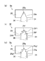
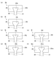
- FIGS. 6 to 8 are plan views of the concave-convex fitting structure 9.
- FIG. 6 to 8 are plan views of the concave-convex fitting structure 9.
- FIG. 6 The shape of the concave-convex fitting structure 9 described below is a shape viewed from above.
- the basic concave-convex fitting structure 9 is rectangular.
- the convex shape of the tooth convex portion 35a is rectangular, and the concave shape of the yoke concave portion 25a is rectangular.
- the concave-convex fitting structure 9b of FIG. 6(b) is a structure in which a smaller fitting structure is added to the concave-convex fitting structure 9a of FIG. 6(a).
- two small rectangular small protrusions 35b1 are provided on each of the left and right surfaces of the rectangular tooth protrusion 35b.
- two small rectangular recesses 25b1 are provided on each of the left and right surfaces of the yoke recess 25b. The small concave portion 25b1 and the small convex portion 35b1 are fitted.
- the concave-convex fitting structure 9c of FIG. 6(c) is a structure in which a smaller fitting structure is added to the upper side of the concave-convex fitting structure 9a of FIG.
- two small rectangular small protrusions 35c1 are provided on each of the left and right surfaces of the rectangular teeth protrusion 35c, and three small protrusions 35c2 are provided on the surface in the projecting direction.
- two small rectangular recesses 25c1 are provided on each of the left and right surfaces of the yoke recess 25c, and three small rectangular recesses 25c2 are provided on the recessed surface.
- the small protrusions 35c1 and 35c2 are fitted with the small recesses 25c1 and 25c2.
- the fitting structure 9a by forming the concave-convex fitting structure 9a into a rectangular concave-convex shape fitting, the fitting structure can be simplified, and the manufacturing cost can be reduced.
- the fitting accuracy that is, the fixing accuracy of the yoke 20 and the teeth 30 can be increased. Moreover, it is possible to prevent the teeth 30 from coming off to the rotor 2 side.
- the basic concave-convex fitting structure 9 is triangular.
- the convex shape of the tooth convex portion 35e is triangular, and the concave shape of the yoke concave portion 25e is triangular.
- the concave-convex fitting structure 9f of FIG. 7(b) is a structure in which a smaller fitting structure is added to the concave-convex fitting structure 9e of FIG. 7(a). Specifically, as shown in the drawing, two small rectangular small protrusions 35f1 are provided on each of the left and right surfaces of the triangular tooth protrusion 35f. In the yoke 20, two small rectangular recesses 25f1 are provided on each of the left and right surfaces of the yoke recess 25f. The small concave portion 25f1 and the small convex portion 35f1 are fitted.
- the fitting structure 9e As shown in FIG. 7(a), by forming the concave-convex fitting structure 9e into a rectangular concave-convex shape fitting, the fitting structure can be simplified, and the manufacturing cost can be reduced. Moreover, since the unevenness is triangular, fitting is easy. As shown in FIGS. 7B and 7C, by adding a small uneven fitting structure, the fitting accuracy, that is, the fixing accuracy of the yoke 20 and the teeth 30 can be increased. Moreover, it is possible to prevent the teeth 30 from coming off to the rotor 2 side.
- the basic concave-convex fitting structure 9 is wedge-shaped.
- the convex shape of the tooth convex portion 35h is a wedge shape that widens radially outward (projecting direction side).
- the concave shape of the yoke concave portion 25h is an inverted wedge shape that matches the wedge shape of the tooth convex portion 35h.
- the convex shape of the tooth convex portion 35i protrudes so as to widen from the tooth base portion 31 and becomes a rectangular shape with a constant width from the middle.
- the recessed shape of the yoke recessed portion 25i is gradually widened halfway so as to match the shape of the teeth protruded portion 35i, and becomes equal in width from the middle.
- the convex shape of the tooth convex portion 35j protrudes from the tooth base portion 31 with the same width, and the radially outer side (protruding direction side) becomes wider from the middle.
- the concave shape of the yoke concave portion 25j has a uniform width halfway so as to match the shape of the teeth convex portion 35j, and the radially outer side (protruding direction side) widens from the middle.
- the convex shape of the tooth convex portion 35k protrudes from the tooth base portion 31 with a uniform width, and the radially outer side (protruding direction side) becomes wide from the middle, and further the width becomes uniform from the middle. It's becoming
- the concave shape of the yoke concave portion 25k has a uniform width halfway so as to match the shape of the teeth convex portion 35k, the radially outer side (protruding direction side) becomes wider from the middle, and the width becomes uniform from the middle. It has become.
- the convex shape of the tooth convex portion 35l protrudes from the tooth base portion 31 so as to gradually become narrower, and is widened from the middle.
- the recessed shape of the yoke recessed portion 25l is formed so that the width gradually becomes narrower halfway so as to match the shape of the teeth projected portion 35l, and the width gradually widens from the middle.
- the convex shape of the tooth convex portion 35m protrudes from the tooth base portion 31 so as to gradually become narrower, gradually widens in the middle, and becomes equal in width from the middle.
- the concave shape of the yoke concave portion 25m is formed so that the width gradually narrows halfway so as to match the shape of the teeth convex portion 35m.
- FIG. 9 shows a concave-convex fitting structure 9n of a modification, in which the convex-concave fitting structure 9 (9a to 9m) described above is reversed. That is, the concave-convex fitting structure 9n is a structure in which the tooth concave portion 36 provided in the teeth 30 in a concave shape and the yoke convex portion 26 provided in the yoke 20 in a convex shape are fitted.
- the yoke convex portion 26 is formed in a wedge shape with a wider center side in the radial direction.
- the tooth recesses 36 are formed in an inverted wedge shape that matches the wedge shape of the yoke protrusions 26 .
- teeth 30 are prepared by laminating a plurality of magnetic steel sheets in the axial direction and fixing them in close contact.
- the tooth base 31 of the tooth 30 is covered with a thin first resin composition around the tooth base 31 by insert molding to form a tooth resin coating portion 37. is formed on the surface of the tooth base 31 .
- a method of manufacturing the yoke 20 will be described with particular attention to a method of forming the yoke resin coating portion 27 (yoke coating step) with reference to FIGS. 11 and 2 and 3 described above.
- a yoke 20 is prepared by laminating a plurality of magnetic steel sheets in the axial direction and fixing them in close contact.
- the surface of the yoke 20 on the slot side that is, the inner peripheral surface 23
- a covering portion 27 is formed.
- ⁇ Fitting Step (1) of Yoke 20 and Teeth 30> a method of manufacturing stator 10 will be described with particular focus on the step of fitting yoke 20 and teeth 30 (step of fixing teeth).
- a plurality of teeth 30 provided separately from the yoke 20 and having coils 50 wound around the cylindrical yoke 20 are fixed on the cylindrical inner peripheral surface 23 of the yoke 20 . Install so that it protrudes toward the direction center.
- a coil winding process of winding the coil 50 around the teeth 30 is included in the process prior to the teeth fixing process.
- Coil winding process As shown in FIG. 12(a), first, a wound coil 50 is prepared. At this time, the coil 50 is distributed winding or concentrated winding depending on the type of the motor 100 . Next, as shown in FIG. 12B, the teeth 30 provided with the tooth resin coating portions 37 in advance by the tooth resin coating step are prepared, and the teeth 30 are inserted into the holes of the coils 50 . At this time, the coil 50 is attached so as to wind around the tooth base 31 on which the tooth resin coating portion 37 is formed. If it is difficult to insert the teeth 30 into the holes of the coils 50 due to the shape of the teeth 30, the coils 50 may be wound around the teeth bases 31 by a coil winding device. In any case, the coil 50 is wound around the teeth 30 before the teeth 30 are fixed to the yoke 20 .
- Teeth fixing process Subsequently, as shown in FIG. 12(c), the tooth projections 35 of the teeth 30 around which the coils 50 are wound are attached to the yokes of the yoke 20 on which the yoke resin coating portion 27 is formed in advance by the yoke coating process. It fits into the recess 25 . As a result, the concave-convex fitting structure 9 in which the yoke 20 and the teeth 30 are fitted is obtained.
- the coils 50 are wound around a plurality of teeth 30 by distributed winding, in the teeth fixing step, the plurality of teeth 30 and the coils 50 formed as one unit by distributed winding are attached to the yoke 20 in unit units. can be done.
- the tooth convex portion 35 of the tooth 30 having the tooth resin coating portion 37 formed on the tooth base portion 31 is replaced with the yoke concave portion of the yoke 20 having the yoke resin coating portion 27 formed thereon. Fit in 25.
- a coil winding device is used to wind the coil 50 around the tooth base 31 on which the tooth resin coating portion 37 is formed.
- the method for manufacturing the stator 10 of this embodiment has the following features.
- the manufacturing method of the stator 10 includes a cylindrical yoke 20 and a plurality of teeth 30 which are provided separately from the yoke 20 and around which the coils 50 are wound. has a tooth fixing step of attaching so as to protrude toward the center in the radial direction, In the tooth 30, the region around which the coil 50 is wound (the tooth resin coating portion 37) is covered with the first cured product of the first resin composition. Since the separately provided yoke 20 and the teeth 30 are fitted together, the operation of providing the teeth resin coating portions 37 on the teeth 30 and winding the coils 50 is facilitated.
- a coil winding process of winding the coil 50 around the teeth 30 is included in the process preceding the teeth fixing process. Since the teeth 30 with the coils 50 wound thereon are prepared in advance and attached to the yoke 20 , damage to the teeth resin coating portions 37 during the process of winding the coils 50 can be suppressed.
- the coil winding step the coil 50 is wound around the plurality of teeth 30 by distributed winding.
- the teeth fixing step a plurality of teeth 30 and coils 50 formed as one unit by distributed winding are attached to the yoke 20 in unit units. Since a unit in which the coils 50 are distributed and wound around a plurality of teeth 30 is prepared in advance and attached to the yoke 20, the coil winding process is facilitated.
- the yoke 20 and the teeth 30 are fixed by the concave-convex fitting structure 9 . Thereby, the fixed state of the yoke 20 and the teeth 30 can be ensured.
- the concave-convex fitting structure 9 is a structure in which the yoke concave portion 25 provided in the yoke 20 in a concave shape and the tooth convex portion 35 provided in the tooth 30 in a convex shape are engaged. Thereby, the fixed state of the yoke 20 and the teeth 30 can be ensured.
- the yoke recesses 25 are formed in a wedge shape that narrows on the radial center side (rotor 2 side), and the tooth protrusions 35 are formed in a reverse wedge shape that matches the wedge shape of the yoke recesses 25 . ing. As a result, it is possible to prevent the teeth 30 from slipping out from the yoke 20 toward the center in the radial direction (toward the rotor 2).
- the concave-convex fitting structure 9 is a structure in which tooth concave portions 36 provided in the teeth 30 in a concave shape and yoke convex portions 26 provided in the yoke 20 in a convex shape are fitted.
- the yoke convex portion 26 is formed in a wedge shape with a wider radial center side,
- the tooth recesses 36 are formed in an inverted wedge shape that matches the wedge shape of the yoke protrusions 26 .
- the stator 10 of this embodiment has the following features.
- the stator 10 includes a cylindrical yoke 20, a plurality of teeth 30 provided separately from the yoke 20, attached to the yoke 20, and having a coil 50 wound thereon;
- the teeth 30 are attached to the cylindrical inner peripheral surface 23 of the yoke 20 so as to protrude toward the center in the radial direction.
- the tooth 30 has a region (the tooth base portion 31, the tooth resin coating portion 37) around which the coil 50 is wound, which is covered with a first cured product obtained by curing the first resin composition. (12)
- the glass transition temperature Tg of the resin (first resin composition) of the tooth resin coating portion 37, that is, the first cured product is 120° C. or higher.
- the motor 100 can be used at high temperatures. In addition, it is possible to cope with the increase in heat generated due to the increase in output of the motor 100 .
- the resin of the tooth resin coating portion 37 contains epoxy resin. This provides high heat resistance and insulation reliability.
- the first resin composition contains a filler as a filler. Thereby, the strength of the tooth resin coating portion 37 can be increased.
- the filler content of the first resin composition is 60% by volume or more. Thereby, the strength of the tooth resin coating portion 37 can be increased.
- the thermal conductivity of the first cured product is 0.5 W/mK or more.
- the yoke 20 has a region facing the slot 40 covered with a second cured product obtained by curing the second resin composition. That is, the region facing the slot 40 is configured as the yoke resin coating portion 27 coated with the second cured material. Insulation between the yoke 20 and the coil 50 can be ensured.
- the glass transition temperature Tg of the second resin composition (the second cured material forming the yoke resin coating portion 27) is 120°C or higher. By using a resin (especially a thermosetting resin) with a glass transition temperature Tg of 120° C. or higher, the motor 100 can be used at high temperatures.
- the second resin composition contains an epoxy resin. This provides high heat resistance and insulation reliability.
- the second resin composition contains a filler as a filler. Thereby, the strength of the yoke resin coating portion 27 can be increased.
- the filler content of the second resin composition is 60% by volume or more. Thereby, the strength of the yoke resin coating portion 27 can be increased.
- the thermal conductivity of the second cured product is 0.5 W/mK or more.
- the yoke 20 and the teeth 30 are fixed by the concave-convex fitting structure 9 (the yoke concave portions 25 and the tooth convex portions 35).
- the fixed state of the yoke 20 and the teeth 30 can be ensured.
- the concave-convex fitting structure 9 concavo-convex fitting structures 9a to 9m
- the yoke concave portion 25 provided in the yoke 20 in a concave shape and the tooth convex portion 35 provided in the tooth 30 in a convex shape are fitted. Structure. Thereby, the fixed state of the yoke 20 and the teeth 30 can be ensured.
- the yoke recess 25 is formed in a wedge shape that narrows toward the radial center side (that is, the rotor 2 side), and the tooth protrusion 35 is formed in a reverse wedge shape that matches the wedge shape of the yoke recess 25. It is Thereby, the fixed state of the yoke 20 and the teeth 30 can be ensured.
- the concave-convex fitting structure 9 (convex-convex fitting structure 9n) is a structure in which the tooth recesses 36 provided in the teeth 30 in a recessed manner and the yoke protrusions 26 provided in the yoke 20 in a protrusive manner are fitted. be.
- the yoke convex portion 26 is formed in a wedge shape with a radial center side widened, and the teeth concave portion 36 is formed in an inverted wedge shape that matches the wedge shape of the yoke convex portion 26 . As a result, it is possible to prevent the teeth 30 from slipping out of the yoke 20 toward the center of the shape.
Landscapes
- Engineering & Computer Science (AREA)
- Power Engineering (AREA)
- Manufacturing & Machinery (AREA)
- Manufacture Of Motors, Generators (AREA)
Abstract
ステータ(10)の製造方法は、筒形状のヨーク(20)に、ヨーク(20)とは別体に設けられておりかつコイル(50)が巻装されている複数のティース(30)を、ヨーク(20)の筒形状の内周面(23)において径方向中心に向かって突設するように取り付けるティース固定工程を有し、ティース(30)において、コイル(50)が巻装されている領域(ティース樹脂被覆部(37))が、第1の樹脂組成物の第1の硬化物により覆われている。
Description
本発明は、ステータの製造方法、ステータ、ティース及びヨークに関する。
モータ(発動機)や発電機のような回転電機において、ステータに設けられたスロットにコイルを収容する際に、スロット内に絶縁紙や樹脂材料を充填して、スロットとコイルの絶縁を確保する技術が知られている(例えば特許文献1参照)。特許文献1では、導体(コイル)とスロットの周壁部との間に、樹脂を注入し硬化させて絶縁層を形成する技術が開示されている。
ところで、モータ製造時の課題として、スロットにコイルを装填する工程が煩雑になる傾向があった。例えば、ティースに樹脂が被覆される構成の場合には、コイルを装填する工程において、ティースを被覆する樹脂を傷つけないようにする必要があり、製造効率の観点で新たな技術が求められていた。
本発明はこのような状況に鑑みなされたものであって、スロットの製造効率を向上させることができる技術を提供することを目的としている。
本発明によれば、以下の発明が提供される。
[1]
筒形状のヨークに、前記ヨークとは別体に設けられておりかつコイルが巻装されている複数のティースを、前記ヨークの筒形状内周面において径方向中心に向かって突設するように取り付けるティース固定工程を有し、
前記ティースにおいて、前記コイルが巻装されている領域が、第1の樹脂組成物が硬化した第1の硬化物により覆われている、ステータの製造方法。
[2]
前記ティース固定工程の前工程において、前記ティースに前記コイルを巻装するコイル巻装工程を有する、[1]に記載のステータの製造方法。
[3]
前記コイル巻装工程は、複数の前記ティースにコイルを分布巻きにより巻装し、
前記ティース固定工程は、分布巻きにより一つのユニットとなった複数の前記ティースと前記コイルとを、ユニット単位で前記ヨークに取り付ける、[2]に記載のステータの製造方法。
[4]
前記コイル巻装工程の前工程において、前記ティースの前記コイルが巻装される領域を前記第1の硬化物で被覆するティース樹脂被覆工程を有する、[2]または[3]に記載のステータの製造方法。
[5]
前記ティース固定工程の前工程において、前記ヨークのスロットに面する領域を第2の樹脂組成物が硬化した第2の硬化物で被覆するヨーク被覆工程を有する、[1]から[4]までのいずれか1に記載のステータの製造方法。
[6]
前記ヨークと前記ティースは、凹凸嵌合構造により固定される、[1]から[5]までのいずれか1に記載のステータの製造方法。
[7]
前記凹凸嵌合構造は、前記ヨークに凹状に設けられたヨーク凹部と、前記ティースに凸状に設けられたティース凸部とが嵌合する構造である、[6]に記載のステータの製造方法。
[8]
前記ヨーク凹部は、径方向中心側が狭くなった楔形状に形成されており、
前記ティース凸部は、前記ヨーク凹部の楔形状に合致する逆楔形状に形成されている、[7]に記載のステータの製造方法。
[9]
前記凹凸嵌合構造は、前記ティースに凹状に設けられたティース凹部と、前記ヨークに凸状に設けられたヨーク凸部とが嵌合する構造である、[6]に記載のステータの製造方法。
[10]
前記ヨーク凸部は、径方向中心側が広くなった楔形状に形成されており、
前記ティース凹部は、前記ヨーク凸部の楔形状に合致する逆楔形状に形成されている、[9]に記載のステータの製造方法。
[11]
筒形状のヨークと、
前記ヨークとは別体に設けられて且つ前記ヨークに取り付けられているとともに、コイルが巻装されている複数のティースと、を有し、
前記ティースは、前記ヨークの筒形状内周面において径方向中心に向かって突設するように取り付けられており、
前記ティースは、前記コイルが巻装されている領域が、第1の樹脂組成物が硬化した第1の硬化物により覆われている、ステータ。
[12]
前記第1の樹脂組成物のガラス転移温度Tgが120℃以上である、
[11]に記載のステータ。
[13]
前記第1の樹脂組成物はエポキシ樹脂を含有する、[11]または[12]に記載のステータ。
[14]
前記第1の樹脂組成物は充填剤としてフィラーを含有する、
[11]から[13]までのいずれか1に記載のステータ。
[15]
前記第1の樹脂組成物のフィラー含有量が60体積%以上である、[14]に記載のステータ。
[16]
前記第1の硬化物の熱伝導率が0.5W/mK以上である、[11]から[15]までのいずれか1に記載のステータ。
[17]
前記ヨークは、スロットに面する領域が、第2の樹脂組成物が硬化した第2の硬化物で被覆されている、[11]から[16]までのいずれか1に記載のステータ。
[18]
前記第2の樹脂組成物のガラス転移温度Tgが120℃以上である、
[17]に記載のステータ。
[19]
前記第2の樹脂組成物はエポキシ樹脂を含有する、[17]または[18]に記載のステータ。
[20]
前記第2の樹脂組成物は充填剤としてフィラーを含有する、
[17]から[19]までのいずれか1に記載のステータ。
[21]
前記第2の樹脂組成物のフィラー含有量が60体積%以上である、[20]に記載のステータ。
[22]
前記第2の硬化物の熱伝導率が0.5W/mK以上である、[17]から[21]までのいずれか1に記載のステータ。
[23]
前記ヨークと前記ティースは、凹凸嵌合構造により固定されている、[11]から[22]までのいずれか1に記載のステータ。
[24]
前記凹凸嵌合構造は、前記ヨークに凹状に設けられたヨーク凹部と、前記ティースに凸状に設けられたティース凸部とが嵌合する構造である、[23]に記載のステータ。
[25]
前記ヨーク凹部は、径方向中心側が狭くなった楔形状に形成されており、
前記ティース凸部は、前記ヨーク凹部の楔形状に合致する逆楔形状に形成されている、[24]に記載のステータ。
[26]
前記凹凸嵌合構造は、前記ティースに凹状に設けられたティース凹部と、前記ヨークに凸状に設けられたヨーク凸部とが嵌合する構造である、[23]に記載のステータ。
[27]
前記ヨーク凸部は、径方向中心側が広くなった楔形状に形成されており、
前記ティース凹部は、前記ヨーク凸部の楔形状に合致する逆楔形状に形成されている、[26]に記載のステータ。
[28]
別体に設けられた筒形状のヨークの筒内周面に取り付けられ、かつコイルが巻装されるティースであって、
前記コイルが巻装される領域が樹脂により覆われている、ティース。
[29]
別体に設けられた複数のティースが取り付けられるヨークであって、
前記ティースが取り付けられたときに形成されるスロットに面する領域が樹脂により覆われている、ヨーク。
本発明によれば、スロットの製造効率を向上させることができる技術を提供することができる。
<概要>
本実施形態では、回転電機(電動機、発電機または電動機/発電機の両用機)として電動機(モータ)に適用した例を説明する。図1はモータ100の回転軸方向と垂直な方向の断面図を模式的に示している。
本実施形態では、回転電機(電動機、発電機または電動機/発電機の両用機)として電動機(モータ)に適用した例を説明する。図1はモータ100の回転軸方向と垂直な方向の断面図を模式的に示している。
本実施形態の概要は次の通りである。
モータ100に用いられるステータ10は、筒形状のヨーク20と、ヨーク20とは別体に設けられて且つヨーク20に取り付けられているとともに、コイル50が巻装されている複数のティース30と、を有する。
ティース30は、ヨーク20の筒形状内周面において径方向中心に向かって突設するように取り付けられている。また、ティース30は、コイル50が巻装されている領域(ティース基部31のティース樹脂被覆部37)が、第1の樹脂組成物が硬化し第1の硬化物により覆われている。
すなわち、ヨーク20とティース30とは別体に設けられており、それらを組み付けることでステータ10が得られる。
なお、本実施形態は主にステータ10、ヨーク20及びティース30の構造とステータ10の製造方法に特徴を有する。したがって、以下では、それらに着目して説明し、モータ100の構成要素の一般的な特徴については詳細な説明を適宜省略する。
<モータ100の基本構造>
図1に示すように、モータ100は、ケース1と、ケース1の内部に収容されたロータ2、ステータ10、及びコイル50とを備える。ケース1は、円筒部1aと、この円筒部1aの軸方向両端を閉塞する側板部(図示せず)とを有して構成される。ケース1の材料として、例えば、アルミニウム合金(鋳物鋳造品)や樹脂材料、それらを組み合わせたものを用いることができる。
図1に示すように、モータ100は、ケース1と、ケース1の内部に収容されたロータ2、ステータ10、及びコイル50とを備える。ケース1は、円筒部1aと、この円筒部1aの軸方向両端を閉塞する側板部(図示せず)とを有して構成される。ケース1の材料として、例えば、アルミニウム合金(鋳物鋳造品)や樹脂材料、それらを組み合わせたものを用いることができる。
<ロータ2>
ロータ2は、ケース1(円筒部1a)の内部に収容されている。ロータ2の中心には出力軸として回転軸3が取り付けられている。回転軸3の両端がそれぞれベアリングを介して側板部に支持されている。これによって、ロータ2は回転軸3を中心に回転自在となっている。
ロータ2は、ケース1(円筒部1a)の内部に収容されている。ロータ2の中心には出力軸として回転軸3が取り付けられている。回転軸3の両端がそれぞれベアリングを介して側板部に支持されている。これによって、ロータ2は回転軸3を中心に回転自在となっている。
ロータ2には永久磁石5が内装されている。具体的には、図1に示すように、複数の永久磁石5が同一円周上に等間隔で配置されている。このとき、隣合う永久磁石5の磁極は互いに異なるように設置されている。
円筒部1aの内周側には円筒型のステータ10が、ロータ2の外周を取り囲むように配置され固定されている。ステータ10の内周面とロータ2の外周面との間には微少な間隙(エアギャップ)が設けられている。
<コイル50>
コイル50は、例えば平角線をU字状とした形状を有し、ティース30を跨いで離間した二つのスロット40に収納されるようにして巻かれている。コイル50は、銅等の良導体であって断面矩形のコイル本体の表面が被覆された構造となっている。
コイル50は、例えば平角線をU字状とした形状を有し、ティース30を跨いで離間した二つのスロット40に収納されるようにして巻かれている。コイル50は、銅等の良導体であって断面矩形のコイル本体の表面が被覆された構造となっている。
<ステータ10>
図2~図5を参照してステータ10及びその構成要素であるヨーク20とティース30とを具体的に説明する。
図2はステータ10の斜視図である。図3はヨーク20の斜視図である。図4はティース30を示しており、図4(a)は斜視図、図4(b)が平面図である。ここではティース樹脂被覆部37が設けられた状態を示している。図5はティース30を示しており、図5(a)は斜視図、図5(b)が平面図である。ここではティース樹脂被覆部37が設けられていない状態を示している。
図2~図5を参照してステータ10及びその構成要素であるヨーク20とティース30とを具体的に説明する。
図2はステータ10の斜視図である。図3はヨーク20の斜視図である。図4はティース30を示しており、図4(a)は斜視図、図4(b)が平面図である。ここではティース樹脂被覆部37が設けられた状態を示している。図5はティース30を示しており、図5(a)は斜視図、図5(b)が平面図である。ここではティース樹脂被覆部37が設けられていない状態を示している。
ステータ10は、複数の電磁鋼板を軸方向に積層し密着固定して設けられている。ステータ10には、軸方向端部(上側または下側)から見たときに、環状に設けられたヨーク20と、ヨーク20からロータ2側(内周側)に向かって延出する複数のティース30とが設けられている。本実施形態のステータ10では、ヨーク20とティース30とは別体として設けられ、複数のティース30がヨーク20に取り付けられて構成されている。ヨーク20とティース30との固定には、ヨーク20のヨーク凹部25とティース30のティース凸部35による凹凸嵌合構造9が用いられる。
<ヨーク20>
ヨーク20は、上面視で環状に設けられた電磁鋼板を軸方向に複数積層し密着固定して設けられている。ヨーク20の内周面には、複数の凹状のヨーク凹部25が周方向に等間隔に設けられている。ヨーク20にティース30を取り付ける際に、それぞれのヨーク凹部25にティース30のティース凸部35が嵌め込まれて固定される。
ヨーク20は、上面視で環状に設けられた電磁鋼板を軸方向に複数積層し密着固定して設けられている。ヨーク20の内周面には、複数の凹状のヨーク凹部25が周方向に等間隔に設けられている。ヨーク20にティース30を取り付ける際に、それぞれのヨーク凹部25にティース30のティース凸部35が嵌め込まれて固定される。
ヨーク20の内周面であって、ヨーク凹部25が設けられていない領域には、樹脂が被覆されている。以下、樹脂が被覆された領域をヨーク樹脂被覆部27という。ヨーク樹脂被覆部27は省かれてもよい。
<ティース30>
複数のティース30は周方向に等間隔に配列されてヨーク20に取り付けられている。隣接するティース30の間の空間がスロット40となる。ティース30は、ヨーク20と同様に、複数の電磁鋼板を軸方向に積層し密着固定して設けられている。ティース30は、図1で示したロータ2の永久磁石5と対応して設けられ、各コイル9を順次励磁していくことにより、これに対応した永久磁石5との吸引、反発によりロータ2が回転する。
複数のティース30は周方向に等間隔に配列されてヨーク20に取り付けられている。隣接するティース30の間の空間がスロット40となる。ティース30は、ヨーク20と同様に、複数の電磁鋼板を軸方向に積層し密着固定して設けられている。ティース30は、図1で示したロータ2の永久磁石5と対応して設けられ、各コイル9を順次励磁していくことにより、これに対応した永久磁石5との吸引、反発によりロータ2が回転する。
ティース30は、上面視で略長方形のティース基部31と、ティース基部31の一端(ロータ2側の端部)に設けられたティース先端部32と、ティース基部31の他端(ロータ2と反対側の端部)に設けられたティース凸部35とを有する。
ティース基部31は、ティース30がヨーク20に取り付けられたときに軸中心側(ロータ2側)に延出する。ティース基部31には、樹脂が被覆されたティース樹脂被覆部37が設けられている。
ティース先端部32は、図1で示すように、モータ100においてロータ2と、所定距離離間して対向する。ティース先端部32は、幅方向、すなわちスロット40の方向に突出する二つの凸部32aを有する。隣接するティース30のティース先端部32の凸部32a間がスロット40の内周側開口となっている。
<ヨーク樹脂被覆部27、ティース樹脂被覆部37>
ティース樹脂被覆部37は、ティース基部31の周縁を第1の樹脂組成物を硬化させた第1の硬化物で一体に周回させて覆っている。
ティース樹脂被覆部37は、ティース基部31の周縁を第1の樹脂組成物を硬化させた第1の硬化物で一体に周回させて覆っている。
ティース樹脂被覆部37は、例えばインサート成形によりティース30(ティース基部31)の周囲に第1の樹脂組成物を薄肉状に周回させて覆う。これによって、ティース30における、積層されている複数の電磁鋼板の固定状態を一層密させることができ、また、ティース30とコイル50との間に絶縁層を構成することができる。
ティース樹脂被覆部37の厚みは、特にスロット40側の壁面において、50μm以上500μm以下である。厚みの下限値は、好ましくは100μm以上であり、より好ましくは150μm以上である。厚みの上限値は、好ましくは400μm以下であり、より好ましくは300μm以下である。上下端面では、ティース樹脂被覆部37の厚みは特に限定はしないが、上記の厚みとすることができる。
厚みの下限値は、インサート成形時においてステータ軸長(すなわちステータ10の厚み)に対して、金型とティース30との間の極狭部における樹脂組成物の流動性確保の観点から、上記の範囲にすることが好ましい。
厚みの上限値は、コイル50をティース30に巻装しスロット8に配置する構造において、スロット40内の空間利用効率(すなわちコイル50の占有率)を高めて、使用可能なコイル50のサイズの自由度や磁束密度等性能確保の観点から、上記の範囲にすることが好ましい。
ヨーク樹脂被覆部27は、ヨーク20の内周面であってヨーク凹部25が設けられていない領域を、第2の樹脂組成物を硬化させた第2の硬化物で覆っている。ヨーク樹脂被覆部27の厚みは、ティース樹脂被覆部37と同程度とすることができる。ヨーク樹脂被覆部27は、ティース樹脂被覆部37と同様の機能を発揮する。すなわち、ヨーク樹脂被覆部27は、積層されている複数の電磁鋼板を密着固定することができ、また、ヨーク20とコイル50との間に絶縁層を構成することができる。
<ヨーク樹脂被覆部27、ティース樹脂被覆部37の物性>
ヨーク樹脂被覆部27、ティース樹脂被覆部37を構成する第1及び第2の硬化物(第1及び第2の樹脂組成物)の物性は例えば以下の通りである。
樹脂材料の硬化物の熱伝導率は0.5W/mK以上である。熱伝導率の下限は、好ましくは1.0W/mK以上であり、より好ましくは2W/mK以上である。熱伝導率の上限は、特に限定しないが、現実的な値として10W/mKである。
ヨーク樹脂被覆部27、ティース樹脂被覆部37を構成する第1及び第2の硬化物(第1及び第2の樹脂組成物)の物性は例えば以下の通りである。
樹脂材料の硬化物の熱伝導率は0.5W/mK以上である。熱伝導率の下限は、好ましくは1.0W/mK以上であり、より好ましくは2W/mK以上である。熱伝導率の上限は、特に限定しないが、現実的な値として10W/mKである。
第1及び第2の硬化物のガラス転移温度Tgは120℃以上であり、好ましくは140℃以上、より好ましくは160℃以上である。ガラス転移温度Tgを上記範囲とすることで、モータ100を高温下で使用することができ、またコイル50の発熱に強くなり高出力で使用することができる。
<ヨーク樹脂被覆部27、ティース樹脂被覆部37の材料>
第1及び第2の樹脂組成物を以下に具体的に説明する。以下では、ティース樹脂被覆部37について説明するが、ヨーク樹脂被覆部27についても同様の材料を用いることができる。また、スロット40には、コイル50間の空間を埋めるように樹脂材料を充填することができ、そのような樹脂材料としてヨーク樹脂被覆部27に用いる樹脂材料を用いることができる。
第1及び第2の樹脂組成物を以下に具体的に説明する。以下では、ティース樹脂被覆部37について説明するが、ヨーク樹脂被覆部27についても同様の材料を用いることができる。また、スロット40には、コイル50間の空間を埋めるように樹脂材料を充填することができ、そのような樹脂材料としてヨーク樹脂被覆部27に用いる樹脂材料を用いることができる。
ヨーク樹脂被覆部27の第1の樹脂組成物は、熱硬化性樹脂(A)、充填剤(B)、及び硬化剤(C)などを含むことが好ましい。
[熱硬化性樹脂(A)]
熱硬化性樹脂(A)としては、たとえば、エポキシ樹脂、シアネート樹脂、ポリイミド樹脂、ベンゾオキサジン樹脂、不飽和ポリエステル樹脂、フェノール樹脂、メラミン樹脂、シリコーン樹脂、ビスマレイミド樹脂、フェノキシ樹脂、及びアクリル樹脂等が挙げられる。熱硬化性樹脂(A)として、これらの中の1種類を単独で用いてもよいし、2種類以上を併用してもよい。
なかでも、高い絶縁性を有する観点から、熱硬化性樹脂(A)としては、エポキシ樹脂、フェノール樹脂、及びフェノキシ樹脂であることが好ましい。成形時における極狭部の流動確保の観点から、エポキシ樹脂が特に好ましい。
熱硬化性樹脂(A)としては、たとえば、エポキシ樹脂、シアネート樹脂、ポリイミド樹脂、ベンゾオキサジン樹脂、不飽和ポリエステル樹脂、フェノール樹脂、メラミン樹脂、シリコーン樹脂、ビスマレイミド樹脂、フェノキシ樹脂、及びアクリル樹脂等が挙げられる。熱硬化性樹脂(A)として、これらの中の1種類を単独で用いてもよいし、2種類以上を併用してもよい。
なかでも、高い絶縁性を有する観点から、熱硬化性樹脂(A)としては、エポキシ樹脂、フェノール樹脂、及びフェノキシ樹脂であることが好ましい。成形時における極狭部の流動確保の観点から、エポキシ樹脂が特に好ましい。
エポキシ樹脂としては、たとえば、ビスフェノールA型エポキシ樹脂、ビスフェノールF型エポキシ樹脂、ビスフェノールE型エポキシ樹脂、ビスフェノールS型エポキシ樹脂、ビスフェノールM型エポキシ樹脂(4,4'-(1,3-フェニレンジイソプリジエン)ビスフェノール型エポキシ樹脂)、ビスフェノールP型エポキシ樹脂(4,4'-(1,4-フェニレンジイソプリジエン)ビスフェノール型エポキシ樹脂)、ビスフェノールZ型エポキシ樹脂(4,4'-シクロヘキシジエンビスフェノール型エポキシ樹脂)等のビスフェノール型エポキシ樹脂;フェノールノボラック型エポキシ樹脂、クレゾールノボラック型エポキシ樹脂、トリスフェノール基メタン型ノボラック型エポキシ樹脂、テトラフェノール基エタン型ノボラック型エポキシ樹脂、縮合環芳香族炭化水素構造を有するノボラック型エポキシ樹脂等のノボラック型エポキシ樹脂;ビフェニル型エポキシ樹脂;キシリレン型エポキシ樹脂、ビフェニルアラルキル型エポキシ樹脂等のアリールアルキレン型エポキシ樹脂;ナフチレンエーテル型エポキシ樹脂、ナフトール型エポキシ樹脂、ナフタレンジオール型エポキシ樹脂、2官能ないし4官能エポキシ型ナフタレン樹脂、ビナフチル型エポキシ樹脂、ナフタレンアラルキル型エポキシ樹脂等のナフタレン型エポキシ樹脂;アントラセン型エポキシ樹脂;フェノキシ型エポキシ樹脂;ジシクロペンタジエン型エポキシ樹脂;ノルボルネン型エポキシ樹脂;アダマンタン型エポキシ樹脂;フルオレン型エポキシ樹脂等が挙げられる。これらの中の1種類を単独で用いてもよいし、2種類以上を併用してもよい。
エポキシ樹脂の中でも、耐熱性及び絶縁信頼性をより一層向上できる観点から、ビスフェノール型エポキシ樹脂、ノボラック型エポキシ樹脂、ビフェニル型エポキシ樹脂、アリールアルキレン型エポキシ樹脂、ナフタレン型エポキシ樹脂、アントラセン型エポキシ樹脂、ジシクロペンタジエン型エポキシ樹脂からなる群から選択される1種または2種以上であることが好ましい。
フェノール樹脂としては、たとえば、フェノールノボラック樹脂、クレゾールノボラック樹脂、ビスフェノールAノボラック樹脂等のノボラック型フェノール樹脂、及びレゾール型フェノール樹脂等が挙げられる。これらの中の1種類を単独で用いてもよいし、2種類以上を併用してもよい。
フェノール樹脂の中でも、フェノールノボラック樹脂であることが好ましい。
フェノール樹脂の中でも、フェノールノボラック樹脂であることが好ましい。
熱硬化性樹脂(A)の含有量は、第1の樹脂組成物(ティース樹脂被覆部37)の樹脂組成物全量に対し、1質量%以上が好ましく、5質量%以上がより好ましい。一方、当該含有量は、第1の樹脂組成物(ティース樹脂被覆部37)の樹脂組成物全量に対し、30質量%以下が好ましく、20質量%以下がより好ましい。
熱硬化性樹脂(A)の含有量が上記下限値以上であると、第1の樹脂組成物(ティース樹脂被覆部37)の樹脂組成物全量のハンドリング性が向上し、特にティース樹脂被覆部37におけるスロット40側の壁面の樹脂層を形成するのが容易となるとともに、ティース樹脂被覆部37の強度が向上する。
熱硬化性樹脂(A)の含有量が上記上限値以下であると、ティース樹脂被覆部37の線膨張率や弾性率がより一層向上したり、熱伝導性がより一層向上したりする。
熱硬化性樹脂(A)の含有量が上記下限値以上であると、第1の樹脂組成物(ティース樹脂被覆部37)の樹脂組成物全量のハンドリング性が向上し、特にティース樹脂被覆部37におけるスロット40側の壁面の樹脂層を形成するのが容易となるとともに、ティース樹脂被覆部37の強度が向上する。
熱硬化性樹脂(A)の含有量が上記上限値以下であると、ティース樹脂被覆部37の線膨張率や弾性率がより一層向上したり、熱伝導性がより一層向上したりする。
[充填剤(B)]
本実施形態における充填剤(B)は、ティース樹脂被覆部37の熱伝導性を向上させるとともに強度を得る観点から用いられる。
本実施形態における充填剤(B)は、ティース樹脂被覆部37の熱伝導性を向上させるとともに強度を得る観点から用いられる。
充填剤(B)としては、無機充填剤が好ましく、熱伝導性フィラーであることが特に好ましい。より具体的には、充填剤(B)としては、熱伝導性と電気絶縁性とのバランスを図る観点から、たとえば、シリカ、アルミナ、窒化ホウ素、窒化アルミニウム、及び炭化ケイ素等が挙げられる。これらは1種を単独で用いても、2種以上を併用してもよい。なかでも、充填剤(B)は、アルミナ、窒化ホウ素であることが好ましい。
充填剤(B)の含有量は、すなわち上記のフィラーの含有量は、樹脂組成物全量に対し、60質量%以上が好ましい。
[硬化剤(C)]
樹脂組成物は、熱硬化性樹脂(A)としてエポキシ樹脂、またはフェノール樹脂を用いる場合、さらに硬化剤(C)を含むことが好ましい。
樹脂組成物は、熱硬化性樹脂(A)としてエポキシ樹脂、またはフェノール樹脂を用いる場合、さらに硬化剤(C)を含むことが好ましい。
硬化剤(C)としては、硬化触媒(C-1)及びフェノール系硬化剤(C-2)から選択される1種以上を用いることができる。
硬化触媒(C-1)としては、たとえば、ナフテン酸亜鉛、ナフテン酸コバルト、オクチル酸スズ、オクチル酸コバルト、ビスアセチルアセトナートコバルト(II)、トリスアセチルアセトナートコバルト(III)等の有機金属塩;トリエチルアミン、トリブチルアミン、1,4-ジアザビシクロ[2.2.2]オクタン等の3級アミン類;2-フェニル-4-メチルイミダゾール、2-エチル-4-メチルイミダゾール、2,4-ジエチルイミダゾール、2-フェニル-4-メチル-5-ヒドロキシイミダゾール、2-フェニル-4,5-ジヒドロキシメチルイミダゾール等のイミダゾール類;トリフェニルホスフィン、トリ-p-トリルホスフィン、テトラフェニルホスホニウム・テトラフェニルボレート、トリフェニルホスフィン・トリフェニルボラン、1,2-ビス-(ジフェニルホスフィノ)エタン等の有機リン化合物;フェノール、ビスフェノールA、ノニルフェノール等のフェノール化合物;酢酸、安息香酸、サリチル酸、p-トルエンスルホン酸等の有機酸;等、またはこの混合物が挙げられる。硬化触媒(C-1)として、これらの中の誘導体も含めて1種類を単独で用いることもできるし、これらの誘導体も含めて2種類以上を併用したりすることもできる。
硬化触媒(C-1)の含有量は、特に限定されないが、樹脂組成物全量に対し、0.001質量%以上1質量%以下が好ましい。
また、フェノール系硬化剤(C-2)としては、フェノールノボラック樹脂、クレゾールノボラック樹脂、トリスフェノールメタン型ノボラック樹脂、ナフトールノボラック樹脂、アミノトリアジンノボラック樹脂等のノボラック型フェノール樹脂;テルペン変性フェノール樹脂、ジシクロペンタジエン変性フェノール樹脂等の変性フェノール樹脂;フェニレン骨格及び/又はビフェニレン骨格を有するフェノールアラルキル樹脂、フェニレン骨格及び/又はビフェニレン骨格を有するナフトールアラルキル樹脂等のアラルキル型樹脂;ビスフェノールA、ビスフェノールF等のビスフェノール化合物;レゾール型フェノール樹脂等が挙げられ、これらは1種類を単独で用いても2種類以上を併用してもよい。
これらの中でも、ガラス転移温度の向上及び線膨張係数の低減の観点から、フェノール系硬化剤(C-2)がノボラック型フェノール樹脂またはレゾール型フェノール樹脂が好ましい。
これらの中でも、ガラス転移温度の向上及び線膨張係数の低減の観点から、フェノール系硬化剤(C-2)がノボラック型フェノール樹脂またはレゾール型フェノール樹脂が好ましい。
フェノール系硬化剤(C-2)の含有量は、特に限定されないが、樹脂組成物全量に対し、1質量%以上が好ましく、5質量%以上がより好ましい。一方、当該含有量は、樹脂組成物全量に対し、30質量%以下が好ましく、15質量%以下がより好ましい。
[カップリング剤(D)]
樹脂組成物は、カップリング剤(D)を含んでもよい。カップリング剤(D)は、熱硬化性樹脂(A)と充填剤(B)との界面の濡れ性を向上させることができる。
樹脂組成物は、カップリング剤(D)を含んでもよい。カップリング剤(D)は、熱硬化性樹脂(A)と充填剤(B)との界面の濡れ性を向上させることができる。
カップリング剤(D)としては、特に限定されないが、たとえば、エポキシシランカップリング剤、カチオニックシランカップリング剤、アミノシランカップリング剤、チタネート系カップリング剤及びシリコーンオイル型カップリング剤の中から選ばれる1種または2種以上のカップリング剤を使用することが好ましい。
カップリング剤(D)の含有量は、特に限定されないが、充填剤(B)100質量%に対して、0.05質量%以上が好ましく、0.1質量%以上がより好ましい。一方、当該含有量は、充填剤(B)100質量%に対して、3質量%以下が好ましく、2質量%以下がより好ましい。
カップリング剤(D)の含有量は、特に限定されないが、充填剤(B)100質量%に対して、0.05質量%以上が好ましく、0.1質量%以上がより好ましい。一方、当該含有量は、充填剤(B)100質量%に対して、3質量%以下が好ましく、2質量%以下がより好ましい。
[フェノキシ樹脂(E)]
さらに、樹脂組成物は、フェノキシ樹脂(E)を含んでもよい。フェノキシ樹脂(E)を含むことによりティース樹脂被覆部37の耐屈曲性を向上でき、また弾性率を低下させることが可能となり、ティース樹脂被覆部37の応力緩和力を向上させることができる。
さらに、樹脂組成物は、フェノキシ樹脂(E)を含んでもよい。フェノキシ樹脂(E)を含むことによりティース樹脂被覆部37の耐屈曲性を向上でき、また弾性率を低下させることが可能となり、ティース樹脂被覆部37の応力緩和力を向上させることができる。
また、フェノキシ樹脂(E)を含むと、粘度上昇により、流動性が低減し、ボイド等が発生することを抑制できる。また、ティース樹脂被覆部37を金属部材(すなわちティース30)と密着させて用いる場合などに、金属と樹脂組成物の硬化体との密着性を向上できる。
フェノキシ樹脂(E)としては、たとえば、ビスフェノール骨格を有するフェノキシ樹
脂、ナフタレン骨格を有するフェノキシ樹脂、アントラセン骨格を有するフェノキシ樹脂、及びビフェニル骨格を有するフェノキシ樹脂等が挙げられる。また、これらの骨格を複数種有した構造のフェノキシ樹脂を用いることもできる。
脂、ナフタレン骨格を有するフェノキシ樹脂、アントラセン骨格を有するフェノキシ樹脂、及びビフェニル骨格を有するフェノキシ樹脂等が挙げられる。また、これらの骨格を複数種有した構造のフェノキシ樹脂を用いることもできる。
フェノキシ樹脂(E)の含有量は、たとえば、樹脂組成物全量に対して、3質量%以上10質量%以下であることが好ましい。
[離型剤]
樹脂組成物は、好ましくは離型剤を含む。これにより、成形後の離型性を高めることができる。離型剤としては、例えばカルナバワックス等の天然ワックス、モンタン酸エステルワックスや酸化ポリエチレンワックス等の合成ワックス、ステアリン酸亜鉛等の高級脂肪酸及びその金属塩類、ならびにパラフィン等が挙げられる。これらを単独で用いても2種以上を組み合わせて用いてもよい。
樹脂組成物は、好ましくは離型剤を含む。これにより、成形後の離型性を高めることができる。離型剤としては、例えばカルナバワックス等の天然ワックス、モンタン酸エステルワックスや酸化ポリエチレンワックス等の合成ワックス、ステアリン酸亜鉛等の高級脂肪酸及びその金属塩類、ならびにパラフィン等が挙げられる。これらを単独で用いても2種以上を組み合わせて用いてもよい。
離型剤を用いる場合、その含有量は、樹脂成形材料全体中、好ましくは0.01~3質量%、より好ましくは0.05~2質量%である。これにより、離型性向上の効果を確実に得ることができる。その結果、ティース樹脂被覆部37の成形精度を高くすることができる。
[その他の成分]
樹脂組成物には、本発明の効果を損なわない範囲で、ほかに酸化防止剤、レベリング剤等を含むことができる。
樹脂組成物には、本発明の効果を損なわない範囲で、ほかに酸化防止剤、レベリング剤等を含むことができる。
<凹凸嵌合構造9>
図6~8を参照して凹凸嵌合構造9(凹凸嵌合構造9a~9m)のバリエーションを説明する。図6~8は、凹凸嵌合構造9の平面図である。以下で説明する凹凸嵌合構造9の形状は上面視による形状である。
図6~8を参照して凹凸嵌合構造9(凹凸嵌合構造9a~9m)のバリエーションを説明する。図6~8は、凹凸嵌合構造9の平面図である。以下で説明する凹凸嵌合構造9の形状は上面視による形状である。
図6では、基本となる凹凸嵌合構造9が矩形となっている。
図6(a)の凹凸嵌合構造9aでは、ティース凸部35aの凸形状が矩形であり、ヨーク凹部25aの凹形状が矩形である。
図6(a)の凹凸嵌合構造9aでは、ティース凸部35aの凸形状が矩形であり、ヨーク凹部25aの凹形状が矩形である。
図6(b)の凹凸嵌合構造9bでは、図6(a)の凹凸嵌合構造9aに対してより小さな嵌合構造を追加した構造である。具体的には、図示で、矩形のティース凸部35bの左右それぞれの面に二つずつ小さな矩形の小凸部35b1が設けられている。ヨーク20では、ヨーク凹部25bの左右の面のそれぞれに二つずつ小さな矩形の小凹部25b1が設けられている。小凹部25b1と小凸部35b1が嵌合する。
図6(c)の凹凸嵌合構造9cでは、図6(b)の凹凸嵌合構造9aの図示上側(ティース凸部35cの突出方向)により小さな嵌合構造を追加した構造である。具体的には、図示で、矩形のティース凸部35cの左右それぞれの面に二つずつ小さな矩形の小凸部35c1が設けられ、突出方向の面に三つの小凸部35c2が設けられている。ヨーク20では、ヨーク凹部25cの左右の面のそれぞれに二つずつ小さな矩形の小凹部25c1が設けられ、凹み方向の面に3つ小さな矩形の小凹部25c2が設けられている。小凸部35c1、35c2と小凹部25c1、25c2が嵌合する。
図6(d)の凹凸嵌合構造9dでは、図6(b)の凹凸嵌合構造9bの矩形の小凹部25b1と小凸部35b1を、それぞれ上面視で三角形の小凹部25d1と小凸部35d1としたものである。
図6(a)のように凹凸嵌合構造9aを矩形の凹凸形状の嵌合とすることで、嵌合構造をシンプルにすることができ、製造コスト等を抑制できる。
図6(b)~(d)のように、小さな凹凸嵌合構造を追加することで、嵌合精度、すなわちヨーク20とティース30の固定精度を高くすることができる。また、ティース30がロータ2側に外れてしまうことを防止できる。
図6(b)~(d)のように、小さな凹凸嵌合構造を追加することで、嵌合精度、すなわちヨーク20とティース30の固定精度を高くすることができる。また、ティース30がロータ2側に外れてしまうことを防止できる。
図7では、基本となる凹凸嵌合構造9が三角形となっている。
図7(a)の凹凸嵌合構造9eでは、ティース凸部35eの凸形状が三角形であり、ヨーク凹部25eの凹形状が三角形である。
図7(a)の凹凸嵌合構造9eでは、ティース凸部35eの凸形状が三角形であり、ヨーク凹部25eの凹形状が三角形である。
図7(b)の凹凸嵌合構造9fでは、図7(a)の凹凸嵌合構造9eにより小さな嵌合構造を追加した構造である。具体的には、図示で、三角形のティース凸部35fの左右それぞれの面に二つずつ小さな矩形の小凸部35f1が設けられている。ヨーク20では、ヨーク凹部25fの左右の面のそれぞれに二つずつ小さな矩形の小凹部25f1が設けられている。小凹部25f1と小凸部35f1が嵌合する。
図7(c)の凹凸嵌合構造9gでは、図7(b)の凹凸嵌合構造9fの矩形の小凹部25f1と小凸部35f1を、上面視で三角形の小凹部25g1と小凸部35g1としたものである。
図7(a)のように凹凸嵌合構造9eを矩形の凹凸形状の嵌合とすることで、嵌合構造をシンプルにすることができ、製造コスト等を抑制できる。また、凹凸が三角形であるため、嵌合が容易である。
図7(b)、(c)のように、小さな凹凸嵌合構造を追加することで、嵌合精度、すなわちヨーク20とティース30の固定精度を高くすることができる。また、ティース30がロータ2側に外れてしまうことを防止できる。
図7(b)、(c)のように、小さな凹凸嵌合構造を追加することで、嵌合精度、すなわちヨーク20とティース30の固定精度を高くすることができる。また、ティース30がロータ2側に外れてしまうことを防止できる。
図8では、基本となる凹凸嵌合構造9が楔形となっている。
図8(a)の凹凸嵌合構造9hでは、ティース凸部35hの凸形状が径方向外側(突出方向側)において広くなった楔形状である。ヨーク凹部25hの凹形状がティース凸部35hの楔形状に合致する逆楔形状である。
図8(a)の凹凸嵌合構造9hでは、ティース凸部35hの凸形状が径方向外側(突出方向側)において広くなった楔形状である。ヨーク凹部25hの凹形状がティース凸部35hの楔形状に合致する逆楔形状である。
図8(b)の凹凸嵌合構造9iでは、ティース凸部35iの凸形状はティース基部31から拡幅するように突出し、途中から等幅の矩形形状になっている。ヨーク凹部25iの凹形状は、ティース凸部35iの形状に合致するように、途中まで徐々に拡幅し、途中から等幅となっている。
図8(c)の凹凸嵌合構造9jでは、ティース凸部35jの凸形状はティース基部31から等幅で突出し、途中から径方向外側(突出方向側)が広くなっている。ヨーク凹部25jの凹形状は、ティース凸部35jの形状に合致するように、途中まで等幅となっており、途中から径方向外側(突出方向側)が広くなっている。
図8(d)の凹凸嵌合構造9kでは、ティース凸部35kの凸形状はティース基部31から等幅で突出し、途中から径方向外側(突出方向側)が広くなり、さらに途中から等幅となっている。ヨーク凹部25kの凹形状は、ティース凸部35kの形状に合致するように、途中まで等幅となっており、途中から径方向外側(突出方向側)が広くなっており、さらに途中から等幅となっている。
図8(e)の凹凸嵌合構造9lでは、ティース凸部35lの凸形状はティース基部31から徐々に狭くなるように突出し、途中から逆に拡幅している。ヨーク凹部25lの凹形状は、ティース凸部35lの形状に合致するように、途中まで徐々に幅狭となるように形成されており、途中から徐々に拡幅している。
図8(f)の凹凸嵌合構造9mでは、ティース凸部35mの凸形状はティース基部31から徐々に狭くなるように突出し、途中から逆に徐々に拡幅し、更に途中から等幅となっている。ヨーク凹部25mの凹形状は、ティース凸部35mの形状に合致するように、途中まで徐々に幅狭となるように形成されており、途中から徐々に拡幅し、更に途中から等幅となっている。
図9は、変形例の凹凸嵌合構造9nを示しており、上述の凹凸嵌合構造9(9a~9m)と凹凸構造が逆となっている。すなわち凹凸嵌合構造9nは、ティース30に凹状に設けられたティース凹部36と、ヨーク20に凸状に設けられたヨーク凸部26とが嵌合する構造である。ヨーク凸部26は、径方向中心側が広くなった楔形状に形成されている。ティース凹部36は、ヨーク凸部26の楔形状に合致する逆楔形状に形成されている。
<ステータ10の製造方法>
<<ティース30の製造方法(ティース樹脂被覆工程)>>
図10及び上述の図4、5を参照してティース30の製造方法について、特にティース樹脂被覆部37の形成方法(ティース樹脂被覆工程)に着目して説明する。
図10(a)や図4に示すように、複数の電磁鋼板を軸方向に積層し密着固定させたティース30を用意する。
次に、図10(b)や図5に示すように、インサート成形によりティース30のティース基部31の周囲に第1の樹脂組成物を薄肉状に周回させて覆うことで、ティース樹脂被覆部37がティース基部31の表面に形成される。
<<ティース30の製造方法(ティース樹脂被覆工程)>>
図10及び上述の図4、5を参照してティース30の製造方法について、特にティース樹脂被覆部37の形成方法(ティース樹脂被覆工程)に着目して説明する。
図10(a)や図4に示すように、複数の電磁鋼板を軸方向に積層し密着固定させたティース30を用意する。
次に、図10(b)や図5に示すように、インサート成形によりティース30のティース基部31の周囲に第1の樹脂組成物を薄肉状に周回させて覆うことで、ティース樹脂被覆部37がティース基部31の表面に形成される。
<<ヨーク20の製造方法(ヨーク被覆工程)>>
図11及び上述の図2、3を参照してヨーク20の製造方法について、特にヨーク樹脂被覆部27の形成方法(ヨーク被覆工程)に着目して説明する。
図11(a)や図2に示すように、複数の電磁鋼板を軸方向に積層し密着固定させたヨーク20を用意する。
次に、図11(b)や図3に示すように、インサート成形によりヨーク20のスロット側の面(すなわち内周面23)に第2の樹脂組成物を薄肉状に覆うことで、ヨーク樹脂被覆部27が形成される。
図11及び上述の図2、3を参照してヨーク20の製造方法について、特にヨーク樹脂被覆部27の形成方法(ヨーク被覆工程)に着目して説明する。
図11(a)や図2に示すように、複数の電磁鋼板を軸方向に積層し密着固定させたヨーク20を用意する。
次に、図11(b)や図3に示すように、インサート成形によりヨーク20のスロット側の面(すなわち内周面23)に第2の樹脂組成物を薄肉状に覆うことで、ヨーク樹脂被覆部27が形成される。
<ヨーク20とティース30の嵌合工程(1)>
図12を参照して、ステータ10の製造方法について、特にヨーク20とティース30の嵌合工程(ティース固定工程)に着目して説明する。ティース固定工程では、筒形状のヨーク20に、ヨーク20とは別体に設けられておりかつコイル50が巻装されている複数のティース30を、ヨーク20の筒形状の内周面23において径方向中心に向かって突設するように取り付ける。また、ティース固定工程の前工程において、ティース30にコイル50を巻装するコイル巻装工程を有する。
図12を参照して、ステータ10の製造方法について、特にヨーク20とティース30の嵌合工程(ティース固定工程)に着目して説明する。ティース固定工程では、筒形状のヨーク20に、ヨーク20とは別体に設けられておりかつコイル50が巻装されている複数のティース30を、ヨーク20の筒形状の内周面23において径方向中心に向かって突設するように取り付ける。また、ティース固定工程の前工程において、ティース30にコイル50を巻装するコイル巻装工程を有する。
コイル巻装工程:
図12(a)に示すように、まず、巻かれた状態のコイル50を用意する。このとき、モータ100のタイプにより、コイル50は分布巻きや集中巻きとされる。つぎに、図12(b)に示すように、ティース樹脂被覆工程によって予めティース樹脂被覆部37が設けられているティース30を用意し、コイル50の穴にティース30を挿入する。このとき、ティース樹脂被覆部37が形成されているティース基部31の周囲を巻装するようにコイル50が取り付けられる。ティース30の形状により、コイル50の穴にティース30を挿入することが難しい場合、コイル巻き装置によりティース基部31の周囲にコイル50を巻いてもよい。いずれにせよ、ヨーク20にティース30を固定する前に、ティース30にコイル50が巻装される。
図12(a)に示すように、まず、巻かれた状態のコイル50を用意する。このとき、モータ100のタイプにより、コイル50は分布巻きや集中巻きとされる。つぎに、図12(b)に示すように、ティース樹脂被覆工程によって予めティース樹脂被覆部37が設けられているティース30を用意し、コイル50の穴にティース30を挿入する。このとき、ティース樹脂被覆部37が形成されているティース基部31の周囲を巻装するようにコイル50が取り付けられる。ティース30の形状により、コイル50の穴にティース30を挿入することが難しい場合、コイル巻き装置によりティース基部31の周囲にコイル50を巻いてもよい。いずれにせよ、ヨーク20にティース30を固定する前に、ティース30にコイル50が巻装される。
ティース固定工程:
つづいて、図12(c)に示すように、コイル50が巻装された状態のティース30のティース凸部35を、ヨーク被覆工程によって予めヨーク樹脂被覆部27が形成されているヨーク20のヨーク凹部25に嵌め込む。これによって、ヨーク20とティース30とが嵌合した凹凸嵌合構造9が得られる。
なお、複数のティース30にコイル50を分布巻きにより巻装する場合、ティース固定工程では、分布巻きにより一つのユニットとなった複数のティース30とコイル50とを、ユニット単位でヨーク20に取り付けることができる。
つづいて、図12(c)に示すように、コイル50が巻装された状態のティース30のティース凸部35を、ヨーク被覆工程によって予めヨーク樹脂被覆部27が形成されているヨーク20のヨーク凹部25に嵌め込む。これによって、ヨーク20とティース30とが嵌合した凹凸嵌合構造9が得られる。
なお、複数のティース30にコイル50を分布巻きにより巻装する場合、ティース固定工程では、分布巻きにより一つのユニットとなった複数のティース30とコイル50とを、ユニット単位でヨーク20に取り付けることができる。
<ヨーク20とティース30の嵌合工程(2)>
図13を参照して、ステータ10の製造方法におけるヨーク20とティース30の嵌合工程(ティース固定工程)の別の方法について説明する。
図13を参照して、ステータ10の製造方法におけるヨーク20とティース30の嵌合工程(ティース固定工程)の別の方法について説明する。
まず、図13(a)に示すように、ティース基部31にティース樹脂被覆部37が形成されているティース30のティース凸部35を、ヨーク樹脂被覆部27が形成されているヨーク20のヨーク凹部25に嵌め込む。
つづいて、図13(b)に示すように、コイル巻き装置を用いて、ティース樹脂被覆部37が形成されているティース基部31の周囲にコイル50を巻装する。
つづいて、図13(b)に示すように、コイル巻き装置を用いて、ティース樹脂被覆部37が形成されているティース基部31の周囲にコイル50を巻装する。
<実施形態の特徴のまとめ>
以上、本実施形態の特徴をまとめると次の通りである。
(1)本実施形態のステータ10の製造方法は、以下の特徴を有する。
ステータ10の製造方法は、筒形状のヨーク20に、ヨーク20とは別体に設けられておりかつコイル50が巻装されている複数のティース30を、ヨーク20の筒形状の内周面23において径方向中心に向かって突設するように取り付けるティース固定工程を有し、
ティース30において、コイル50が巻装されている領域(ティース樹脂被覆部37)が、第1の樹脂組成物の第1の硬化物により覆われている。
別体に設けられたヨーク20とティース30を嵌合させる構成であるため、ティース30にティース樹脂被覆部37を設けコイル50を巻装する作業が容易になる。
(2)ティース固定工程の前工程において、ティース30にコイル50を巻装するコイル巻装工程を有する。
予めコイル50を巻装したティース30を用意してヨーク20に取り付けるため、コイル50の巻装工程でティース樹脂被覆部37を損傷させてしまうことを抑制できる。
(3)コイル巻装工程は、複数のティース30にコイル50を分布巻きにより巻装し、
ティース固定工程は、分布巻きにより一つのユニットとなった複数のティース30とコイル50とを、ユニット単位でヨーク20に取り付ける。
予め複数のティース30にコイル50を分布巻きしたユニットを用意してからヨーク20に取り付けるため、コイル巻装工程が容易になる。
(4)コイル巻装工程の前工程において、ティース30のコイル50が巻装される領域(ティース基部31、ティース樹脂被覆部37)を第1の硬化物で被覆するティース樹脂被覆工程を有する。
コイル巻装工程の前工程でティース樹脂被覆部37を被覆するため、ティース樹脂被覆工程が容易になり、作業の自由度が向上する。
(5)ティース固定工程の前工程において、ヨーク20のスロット40に面する領域(内周面23)を第2の樹脂組成物が硬化した第2の硬化物で被覆するヨーク被覆工程を有する。
ヨーク20とコイル50の絶縁性を確保することができる。
(6)ヨーク20とティース30は、凹凸嵌合構造9により固定される。これによって、ヨーク20とティース30の固定状態を確実にすることができる。
(7)凹凸嵌合構造9は、ヨーク20に凹状に設けられたヨーク凹部25と、ティース30に凸状に設けられたティース凸部35とが嵌合する構造である。これによって、ヨーク20とティース30の固定状態を確実にすることができる。
(8)ヨーク凹部25は、径方向中心側(ロータ2側)が狭くなった楔形状に形成されており、ティース凸部35は、ヨーク凹部25の楔形状に合致する逆楔形状に形成されている。
これによって、ヨーク20からティース30が径方向中心側(ロータ2側)に抜けることを防止できる。
(9)凹凸嵌合構造9は、ティース30に凹状に設けられたティース凹部36と、ヨーク20に凸状に設けられたヨーク凸部26とが嵌合する構造である。これによって、ヨーク20とティース30の固定状態を確実にすることができる。
(10)ヨーク凸部26は、径方向中心側が広くなった楔形状に形成されており、
ティース凹部36は、ヨーク凸部26の楔形状に合致する逆楔形状に形成されている。
これによって、ヨーク20からティース30が径方向中心側(ロータ2側)に抜けることを防止できる。
(11)本実施形態のステータ10は、以下の特徴を有する。
ステータ10は、筒形状のヨーク20と、
ヨーク20とは別体に設けられて且つヨーク20に取り付けられているとともに、コイル50が巻装されている複数のティース30と、を有し、
ティース30は、ヨーク20の筒形状の内周面23において径方向中心に向かって突設するように取り付けられており、
ティース30は、コイル50が巻装されている領域(ティース基部31、ティース樹脂被覆部37)が、第1の樹脂組成物が硬化した第1の硬化物により覆われている。
(12)ティース樹脂被覆部37の樹脂(第1の樹脂組成物)、すなわち第1の硬化物のガラス転移温度Tgが120℃以上である。ガラス転移温度Tgが120℃以上の樹脂(特に熱硬化性樹脂)を用いることで、モータ100を高温下で使用することができる。また、モータ100の高出力化に伴う発熱増に対応することができる。
(13)ティース樹脂被覆部37の樹脂はエポキシ樹脂を含有する。これによって、高い耐熱性及び絶縁信頼性が得られる。
(14)第1の樹脂組成物は充填剤としてフィラーを含有する。これによって、ティース樹脂被覆部37の強度を高めることができる。
(15)第1の樹脂組成物のフィラー含有量が60体積%以上である。これによって、ティース樹脂被覆部37の強度を高めることができる。
(16)第1の硬化物の熱伝導率が0.5W/mK以上である。これによって、コイル50の熱をステータ10へ円滑に伝えることができる。
(17)ヨーク20は、スロット40に面する領域が、第2の樹脂組成物が硬化した第2の硬化物で被覆されている。すなわち、スロット40に面する領域が、第2の硬化物で被覆されたヨーク樹脂被覆部27として構成されている。ヨーク20とコイル50の絶縁性を確保することができる。
(18)第2の樹脂組成物(ヨーク樹脂被覆部27を構成する第2の硬化物)のガラス転移温度Tgが120℃以上である。ガラス転移温度Tgが120℃以上の樹脂(特に熱硬化性樹脂)を用いることで、モータ100を高温下で使用することができる。また、モータ100の高出力化に伴う発熱増に対応することができる。
(19)第2の樹脂組成物はエポキシ樹脂を含有する。これによって、高い耐熱性及び絶縁信頼性が得られる。
(20)第2の樹脂組成物は充填剤としてフィラーを含有する。これによって、ヨーク樹脂被覆部27の強度を高めることができる。
(21)第2の樹脂組成物のフィラー含有量が60体積%以上である。これによって、ヨーク樹脂被覆部27の強度を高めることができる。
(22)第2の硬化物の熱伝導率が0.5W/mK以上である。
(23)ヨーク20とティース30は、凹凸嵌合構造9(ヨーク凹部25、ティース凸部35)により固定されている。これによって、ヨーク20とティース30の固定状態を確実にすることができる。
(24)凹凸嵌合構造9(凹凸嵌合構造9a~9m)は、ヨーク20に凹状に設けられたヨーク凹部25と、ティース30に凸状に設けられたティース凸部35とが嵌合する構造である。これによって、ヨーク20とティース30の固定状態を確実にすることができる。
(25)ヨーク凹部25は、径方向中心側(すなわちロータ2側)が狭くなった楔形状に形成されており、ティース凸部35は、ヨーク凹部25の楔形状に合致する逆楔形状に形成されている。これによって、ヨーク20とティース30の固定状態を確実にすることができる。
(26)凹凸嵌合構造9(凹凸嵌合構造9n)は、ティース30に凹状に設けられたティース凹部36と、ヨーク20に凸状に設けられたヨーク凸部26とが嵌合する構造である。これによって、ヨーク20とティース30の固定状態を確実にすることができる。
(27)ヨーク凸部26は、径方向中心側が広くなった楔形状に形成されており、ティース凹部36は、ヨーク凸部26の楔形状に合致する逆楔形状に形成されている。
これによって、ヨーク20からティース30が形中心側に抜けることを回避できる。
以上、本発明の実施形態について述べたが、これらは本発明の例示であり、上記以外の様々な構成を採用することもできる。
この出願は、2021年9月15日に出願された日本出願特願2021-150025号を基礎とする優先権を主張し、その開示の全てをここに取り込む。
100 モータ
1 ケース
2 ロータ
3 回転軸
5 永久磁石
9、9a~9n 凹凸嵌合構造
10 ステータ
20 ヨーク
23 内周面
25、25a~25m ヨーク凹部
25b1、25c1、25c2、25d1、25f1、25g1 小凹部
26 ヨーク凸部
27 ヨーク樹脂被覆部
30 ティース
31 ティース基部
32 ティース先端部
32a 凸部
35、35a~35m ティース凸部
35c1、35c2、35d1 小凸部
36 ティース凹部
37 ティース樹脂被覆部
40 スロット
50 コイル
100 モータ
1 ケース
2 ロータ
3 回転軸
5 永久磁石
9、9a~9n 凹凸嵌合構造
10 ステータ
20 ヨーク
23 内周面
25、25a~25m ヨーク凹部
25b1、25c1、25c2、25d1、25f1、25g1 小凹部
26 ヨーク凸部
27 ヨーク樹脂被覆部
30 ティース
31 ティース基部
32 ティース先端部
32a 凸部
35、35a~35m ティース凸部
35c1、35c2、35d1 小凸部
36 ティース凹部
37 ティース樹脂被覆部
40 スロット
50 コイル
100 モータ
Claims (29)
- 筒形状のヨークに、前記ヨークとは別体に設けられておりかつコイルが巻装されている複数のティースを、前記ヨークの筒形状内周面において径方向中心に向かって突設するように取り付けるティース固定工程を有し、
前記ティースにおいて、前記コイルが巻装されている領域が、第1の樹脂組成物が硬化した第1の硬化物により覆われている、ステータの製造方法。 - 前記ティース固定工程の前工程において、前記ティースに前記コイルを巻装するコイル巻装工程を有する、請求項1に記載のステータの製造方法。
- 前記コイル巻装工程は、複数の前記ティースにコイルを分布巻きにより巻装し、
前記ティース固定工程は、分布巻きにより一つのユニットとなった複数の前記ティースと前記コイルとを、ユニット単位で前記ヨークに取り付ける、請求項2に記載のステータの製造方法。 - 前記コイル巻装工程の前工程において、前記ティースの前記コイルが巻装される領域を前記第1の硬化物で被覆するティース樹脂被覆工程を有する、請求項2または3に記載のステータの製造方法。
- 前記ティース固定工程の前工程において、前記ヨークのスロットに面する領域を第2の樹脂組成物が硬化した第2の硬化物で被覆するヨーク被覆工程を有する、請求項1または2に記載のステータの製造方法。
- 前記ヨークと前記ティースは、凹凸嵌合構造により固定される、請求項1または2に記載のステータの製造方法。
- 前記凹凸嵌合構造は、前記ヨークに凹状に設けられたヨーク凹部と、前記ティースに凸状に設けられたティース凸部とが嵌合する構造である、請求項6に記載のステータの製造方法。
- 前記ヨーク凹部は、径方向中心側が狭くなった楔形状に形成されており、
前記ティース凸部は、前記ヨーク凹部の楔形状に合致する逆楔形状に形成されている、請求項7に記載のステータの製造方法。 - 前記凹凸嵌合構造は、前記ティースに凹状に設けられたティース凹部と、前記ヨークに凸状に設けられたヨーク凸部とが嵌合する構造である、請求項6に記載のステータの製造方法。
- 前記ヨーク凸部は、径方向中心側が広くなった楔形状に形成されており、
前記ティース凹部は、前記ヨーク凸部の楔形状に合致する逆楔形状に形成されている、請求項9に記載のステータの製造方法。 - 筒形状のヨークと、
前記ヨークとは別体に設けられて且つ前記ヨークに取り付けられているとともに、コイルが巻装されている複数のティースと、を有し、
前記ティースは、前記ヨークの筒形状内周面において径方向中心に向かって突設するように取り付けられており、
前記ティースは、前記コイルが巻装されている領域が、第1の樹脂組成物が硬化した第1の硬化物により覆われている、ステータ。 - 前記第1の樹脂組成物のガラス転移温度Tgが120℃以上である、
請求項11に記載のステータ。 - 前記第1の樹脂組成物はエポキシ樹脂を含有する、請求項11または12に記載のステータ。
- 前記第1の樹脂組成物は充填剤としてフィラーを含有する、
請求項11または12に記載のステータ。 - 前記第1の樹脂組成物のフィラー含有量が60体積%以上である、請求項14に記載のステータ。
- 前記第1の硬化物の熱伝導率が0.5W/mK以上である、請求項11または12に記載のステータ。
- 前記ヨークは、スロットに面する領域が、第2の樹脂組成物が硬化した第2の硬化物で被覆されている、請求項11または12に記載のステータ。
- 前記第2の樹脂組成物のガラス転移温度Tgが120℃以上である、
請求項17に記載のステータ。 - 前記第2の樹脂組成物はエポキシ樹脂を含有する、請求項17に記載のステータ。
- 前記第2の樹脂組成物は充填剤としてフィラーを含有する、
請求項17に記載のステータ。 - 前記第2の樹脂組成物のフィラー含有量が60体積%以上である、請求項20に記載のステータ。
- 前記第2の硬化物の熱伝導率が0.5W/mK以上である、請求項17に記載のステータ。
- 前記ヨークと前記ティースは、凹凸嵌合構造により固定されている、請求項11または12に記載のステータ。
- 前記凹凸嵌合構造は、前記ヨークに凹状に設けられたヨーク凹部と、前記ティースに凸状に設けられたティース凸部とが嵌合する構造である、請求項23に記載のステータ。
- 前記ヨーク凹部は、径方向中心側が狭くなった楔形状に形成されており、
前記ティース凸部は、前記ヨーク凹部の楔形状に合致する逆楔形状に形成されている、請求項24に記載のステータ。 - 前記凹凸嵌合構造は、前記ティースに凹状に設けられたティース凹部と、前記ヨークに凸状に設けられたヨーク凸部とが嵌合する構造である、請求項23に記載のステータ。
- 前記ヨーク凸部は、径方向中心側が広くなった楔形状に形成されており、
前記ティース凹部は、前記ヨーク凸部の楔形状に合致する逆楔形状に形成されている、請求項26に記載のステータ。 - 別体に設けられた筒形状のヨークの筒内周面に取り付けられ、かつコイルが巻装されるティースであって、
前記コイルが巻装される領域が樹脂により覆われている、ティース。 - 別体に設けられた複数のティースが取り付けられるヨークであって、
前記ティースが取り付けられたときに形成されるスロットに面する領域が樹脂により覆われている、ヨーク。
Priority Applications (1)
| Application Number | Priority Date | Filing Date | Title |
|---|---|---|---|
| JP2023514741A JP7311072B1 (ja) | 2021-09-15 | 2022-09-09 | ステータの製造方法、ステータ、ティース及びヨーク |
Applications Claiming Priority (2)
| Application Number | Priority Date | Filing Date | Title |
|---|---|---|---|
| JP2021-150025 | 2021-09-15 | ||
| JP2021150025 | 2021-09-15 |
Publications (1)
| Publication Number | Publication Date |
|---|---|
| WO2023042760A1 true WO2023042760A1 (ja) | 2023-03-23 |
Family
ID=85602174
Family Applications (1)
| Application Number | Title | Priority Date | Filing Date |
|---|---|---|---|
| PCT/JP2022/033863 WO2023042760A1 (ja) | 2021-09-15 | 2022-09-09 | ステータの製造方法、ステータ、ティース及びヨーク |
Country Status (2)
| Country | Link |
|---|---|
| JP (1) | JP7311072B1 (ja) |
| WO (1) | WO2023042760A1 (ja) |
Citations (4)
| Publication number | Priority date | Publication date | Assignee | Title |
|---|---|---|---|---|
| JP2009254133A (ja) * | 2008-04-07 | 2009-10-29 | Mitsubishi Electric Corp | エレベータのモータ及びエレベータ装置 |
| JP2011244674A (ja) * | 2010-05-21 | 2011-12-01 | Ihi Corp | 分割型ステータ |
| JP2012105420A (ja) * | 2010-11-09 | 2012-05-31 | Mitsubishi Electric Corp | モータの絶縁構造及びその製造方法 |
| JP2021040483A (ja) * | 2017-02-13 | 2021-03-11 | 株式会社三井ハイテック | 固定子積層鉄心の製造方法及び固定子積層鉄心 |
-
2022
- 2022-09-09 JP JP2023514741A patent/JP7311072B1/ja active Active
- 2022-09-09 WO PCT/JP2022/033863 patent/WO2023042760A1/ja active Application Filing
Patent Citations (4)
| Publication number | Priority date | Publication date | Assignee | Title |
|---|---|---|---|---|
| JP2009254133A (ja) * | 2008-04-07 | 2009-10-29 | Mitsubishi Electric Corp | エレベータのモータ及びエレベータ装置 |
| JP2011244674A (ja) * | 2010-05-21 | 2011-12-01 | Ihi Corp | 分割型ステータ |
| JP2012105420A (ja) * | 2010-11-09 | 2012-05-31 | Mitsubishi Electric Corp | モータの絶縁構造及びその製造方法 |
| JP2021040483A (ja) * | 2017-02-13 | 2021-03-11 | 株式会社三井ハイテック | 固定子積層鉄心の製造方法及び固定子積層鉄心 |
Also Published As
| Publication number | Publication date |
|---|---|
| JPWO2023042760A1 (ja) | 2023-03-23 |
| JP7311072B1 (ja) | 2023-07-19 |
Similar Documents
| Publication | Publication Date | Title |
|---|---|---|
| US7939975B2 (en) | Over-mold stator assembly and process for preparation thereof | |
| JP6373854B2 (ja) | ステータ又はロータ | |
| US9325208B2 (en) | Stator with radially mounted teeth | |
| JP5966445B2 (ja) | 固定用樹脂組成物、ロータ、および自動車 | |
| CN110752687A (zh) | 固定用树脂组合物、转子、汽车和转子的制造方法 | |
| CN103730966A (zh) | 用于电动机或发电机的齿 | |
| JP7311072B1 (ja) | ステータの製造方法、ステータ、ティース及びヨーク | |
| US11336131B2 (en) | Stator and electric motor equipped with stator | |
| JP5231981B2 (ja) | 回転電機の回転子 | |
| JP5284847B2 (ja) | 電動機用ステータ又はロータの製造方法 | |
| JP2022092163A (ja) | 電動機用ステータおよび電動機 | |
| JP7375984B2 (ja) | 金型及び樹脂層形成方法 | |
| JP2010178520A (ja) | ステータおよびモータ | |
| JP5971176B2 (ja) | ロータに用いる固定用樹脂組成物 | |
| CN105471151B (zh) | 端部平面化的波纹弹簧和硬化定子线棒护面 | |
| JP2022149379A (ja) | ステータおよび回転電機 | |
| CN114830508A (zh) | 定子用散热盖、包括该散热盖的定子组件及马达 | |
| JP2010200492A (ja) | インシュレータ、ステータおよびモータ | |
| JP2010239707A (ja) | 電動機用ステータ又はロータとその製造方法 | |
| JP2022148598A (ja) | ステータおよびステータの製造方法 | |
| US20240006947A1 (en) | Stator, rotating electric machine, and method of manufacturing stator | |
| JP2024000192A (ja) | ロータおよびロータの製造方法 | |
| JPWO2020021667A1 (ja) | 電子部品装置の製造方法、電子部品装置及び封止材 | |
| CN220711196U (zh) | 用于轴向磁通电机的转子、轴向磁通电机及高电压风扇 | |
| KR102564400B1 (ko) | 개선된 방열 성능을 갖는 전기 모터 및 그 제조 방법 |
Legal Events
| Date | Code | Title | Description |
|---|---|---|---|
| WWE | Wipo information: entry into national phase |
Ref document number: 2023514741 Country of ref document: JP |
|
| 121 | Ep: the epo has been informed by wipo that ep was designated in this application |
Ref document number: 22869907 Country of ref document: EP Kind code of ref document: A1 |
|
| NENP | Non-entry into the national phase |
Ref country code: DE |