WO2023042760A1 - ステータの製造方法、ステータ、ティース及びヨーク - Google Patents
ステータの製造方法、ステータ、ティース及びヨーク Download PDFInfo
- Publication number
- WO2023042760A1 WO2023042760A1 PCT/JP2022/033863 JP2022033863W WO2023042760A1 WO 2023042760 A1 WO2023042760 A1 WO 2023042760A1 JP 2022033863 W JP2022033863 W JP 2022033863W WO 2023042760 A1 WO2023042760 A1 WO 2023042760A1
- Authority
- WO
- WIPO (PCT)
- Prior art keywords
- yoke
- teeth
- tooth
- stator according
- concave
- Prior art date
- Legal status (The legal status is an assumption and is not a legal conclusion. Google has not performed a legal analysis and makes no representation as to the accuracy of the status listed.)
- Ceased
Links
Images





Classifications
-
- H—ELECTRICITY
- H02—GENERATION; CONVERSION OR DISTRIBUTION OF ELECTRIC POWER
- H02K—DYNAMO-ELECTRIC MACHINES
- H02K1/00—Details of the magnetic circuit
- H02K1/06—Details of the magnetic circuit characterised by the shape, form or construction
- H02K1/12—Stationary parts of the magnetic circuit
- H02K1/18—Means for mounting or fastening magnetic stationary parts on to, or to, the stator structures
-
- H—ELECTRICITY
- H02—GENERATION; CONVERSION OR DISTRIBUTION OF ELECTRIC POWER
- H02K—DYNAMO-ELECTRIC MACHINES
- H02K15/00—Processes or apparatus specially adapted for manufacturing, assembling, maintaining or repairing of dynamo-electric machines
- H02K15/06—Embedding prefabricated windings in the machines
-
- H—ELECTRICITY
- H02—GENERATION; CONVERSION OR DISTRIBUTION OF ELECTRIC POWER
- H02K—DYNAMO-ELECTRIC MACHINES
- H02K15/00—Processes or apparatus specially adapted for manufacturing, assembling, maintaining or repairing of dynamo-electric machines
- H02K15/10—Applying solid insulation to windings, stators or rotors, e.g. applying insulating tapes
-
- H—ELECTRICITY
- H02—GENERATION; CONVERSION OR DISTRIBUTION OF ELECTRIC POWER
- H02K—DYNAMO-ELECTRIC MACHINES
- H02K3/00—Details of windings
- H02K3/32—Windings characterised by the shape, form or construction of the insulation
- H02K3/34—Windings characterised by the shape, form or construction of the insulation between conductors or between conductor and core, e.g. slot insulation
Definitions
- the present invention relates to a stator manufacturing method, stator, teeth and yoke.
- Patent Literature 1 discloses a technique for forming an insulating layer by injecting and hardening resin between a conductor (coil) and a peripheral wall portion of a slot.
- the present invention has been made in view of such circumstances, and aims to provide a technology that can improve the efficiency of manufacturing slots.
- a plurality of teeth which are provided separately from the yoke and wound with a coil, are provided on a cylindrical yoke so as to protrude toward the center in the radial direction from the cylindrical inner peripheral surface of the yoke. It has a tooth fixing process to be attached, A method for manufacturing a stator, wherein a region of the tooth around which the coil is wound is covered with a first cured product obtained by curing a first resin composition.
- the concave-convex fitting structure is a structure in which a yoke concave portion provided in a concave shape on the yoke and a tooth convex portion provided in a convex shape on the tooth are engaged. .
- the yoke recess is formed in a wedge shape with a radial center side narrowed
- the method of manufacturing a stator according to [7] wherein the teeth protrusions are formed in an inverted wedge shape that matches the wedge shape of the yoke recesses.
- the concave-convex fitting structure is a structure in which tooth concave portions provided in concave shapes on the teeth and yoke convex portions provided in convex shapes on the yoke are engaged. .
- the yoke convex portion is formed in a wedge shape with a radial center side widened, The manufacturing method of the stator according to [9], wherein the teeth recesses are formed in an inverted wedge shape that matches the wedge shape of the yoke protrusions.
- the glass transition temperature Tg of the first resin composition is 120° C. or higher.
- the stator according to [11] or [12], wherein the first resin composition contains an epoxy resin.
- the first resin composition contains a filler as a filler, The stator according to any one of [11] to [13].
- the stator according to [14], wherein the first resin composition has a filler content of 60% by volume or more.
- the stator according to any one of [11] to [15], wherein the first cured product has a thermal conductivity of 0.5 W/mK or more.
- the second resin composition has a glass transition temperature Tg of 120° C. or higher.
- the second resin composition contains a filler as a filler, The stator according to any one of [17] to [19].
- the stator according to [20], wherein the second resin composition has a filler content of 60% by volume or more.
- the concave-convex fitting structure is a structure in which a yoke concave portion provided in the yoke in a concave shape and a tooth convex portion provided in the tooth in a convex shape are engaged.
- the yoke recess is formed in a wedge shape with a radial center side narrowed
- the concave-convex fitting structure is a structure in which tooth concave portions provided in the teeth in a concave shape and yoke convex portions provided in the yoke in a convex shape are engaged.
- the yoke convex portion is formed in a wedge shape with a radial center side widened,
- FIG. 1 is a perspective view of a stator according to an embodiment
- FIG. It is a perspective view of a yoke according to the embodiment.
- FIG. 1 schematically shows a cross-sectional view of the motor 100 in a direction perpendicular to the rotating shaft direction.
- the outline of this embodiment is as follows.
- the stator 10 used in the motor 100 includes a cylindrical yoke 20, a plurality of teeth 30 provided separately from the yoke 20 and attached to the yoke 20, and around which coils 50 are wound. have The teeth 30 are attached to the cylindrical inner peripheral surface of the yoke 20 so as to protrude toward the center in the radial direction. Further, the teeth 30 are covered with the first cured product obtained by curing the first resin composition in the region around which the coil 50 is wound (the teeth resin coating portion 37 of the teeth base portion 31). That is, the yoke 20 and the teeth 30 are provided separately, and the stator 10 is obtained by assembling them.
- the present embodiment is mainly characterized by the structures of the stator 10, the yoke 20 and the teeth 30 and the manufacturing method of the stator 10. FIG. Therefore, in the following description, attention will be paid to them, and detailed description of general features of the components of the motor 100 will be omitted as appropriate.
- the motor 100 includes a case 1, and a rotor 2, a stator 10, and a coil 50 housed inside the case 1.
- the case 1 includes a cylindrical portion 1a and side plate portions (not shown) closing both ends of the cylindrical portion 1a in the axial direction.
- an aluminum alloy (casting product), a resin material, or a combination thereof can be used as the material of the case 1, for example, an aluminum alloy (casting product), a resin material, or a combination thereof can be used.
- the rotor 2 is accommodated inside the case 1 (cylindrical portion 1a).
- a rotating shaft 3 is attached to the center of the rotor 2 as an output shaft. Both ends of the rotary shaft 3 are supported by the side plate portions via bearings. As a result, the rotor 2 is rotatable around the rotating shaft 3 .
- a permanent magnet 5 is embedded in the rotor 2 . Specifically, as shown in FIG. 1, a plurality of permanent magnets 5 are arranged at regular intervals on the same circumference. At this time, the magnetic poles of adjacent permanent magnets 5 are set to be different from each other.
- a cylindrical stator 10 is arranged and fixed on the inner peripheral side of the cylindrical portion 1 a so as to surround the outer periphery of the rotor 2 .
- a minute gap (air gap) is provided between the inner peripheral surface of the stator 10 and the outer peripheral surface of the rotor 2 .
- the coil 50 has, for example, a U-shaped rectangular wire, and is wound so as to be housed in two slots 40 that are separated from each other across the teeth 30 .
- the coil 50 is made of a good conductor such as copper and has a structure in which the surface of a coil body having a rectangular cross section is covered.
- FIG. 1 is a perspective view of the stator 10.
- FIG. 3 is a perspective view of the yoke 20.
- FIG. 4 shows the teeth 30, FIG. 4(a) being a perspective view and FIG. 4(b) being a plan view.
- a state in which the tooth resin coating portion 37 is provided is shown.
- 5 shows the teeth 30, FIG. 5(a) being a perspective view and FIG. 5(b) being a plan view.
- a state in which the tooth resin coating portion 37 is not provided is shown.
- the stator 10 is provided by laminating a plurality of magnetic steel sheets in the axial direction and fixing them in close contact.
- the stator 10 includes a yoke 20 provided in an annular shape and a plurality of teeth extending from the yoke 20 toward the rotor 2 side (inner peripheral side) when viewed from the axial end (upper or lower side). 30 are provided.
- the yoke 20 and the teeth 30 are separately provided, and the plurality of teeth 30 are attached to the yoke 20 .
- a concave-convex fitting structure 9 with yoke concave portions 25 of the yoke 20 and tooth convex portions 35 of the teeth 30 is used for fixing the yoke 20 and the teeth 30 .
- the yoke 20 is provided by laminating a plurality of magnetic steel plates arranged in an annular shape when viewed from above in the axial direction and closely fixing them.
- a plurality of concave yoke recesses 25 are provided on the inner peripheral surface of the yoke 20 at regular intervals in the circumferential direction.
- a region of the inner peripheral surface of the yoke 20 where the yoke recess 25 is not provided is coated with resin.
- the resin-coated region is referred to as a yoke resin-coated portion 27 .
- the yoke resin coating portion 27 may be omitted.
- a plurality of teeth 30 are arranged at equal intervals in the circumferential direction and attached to the yoke 20 . Spaces between adjacent teeth 30 are slots 40 . Like the yoke 20, the teeth 30 are provided by laminating a plurality of magnetic steel sheets in the axial direction and fixing them in close contact. The teeth 30 are provided corresponding to the permanent magnets 5 of the rotor 2 shown in FIG. Rotate.
- the teeth 30 each include a substantially rectangular tooth base portion 31 when viewed from above, a tooth tip portion 32 provided at one end of the tooth base portion 31 (the end portion on the side of the rotor 2), and the other end of the tooth base portion 31 (the side opposite to the rotor 2). and a teeth convex portion 35 provided at the end of the .
- the tooth base portion 31 extends toward the shaft center side (rotor 2 side) when the tooth 30 is attached to the yoke 20 .
- Teeth base portions 31 are provided with tooth resin-coated portions 37 coated with resin.
- the tooth tip portions 32 face the rotor 2 in the motor 100 with a predetermined distance therebetween.
- the tooth tip portion 32 has two protrusions 32a that protrude in the width direction, that is, in the direction of the slot 40 .
- An opening on the inner peripheral side of the slot 40 is provided between the convex portions 32a of the tooth tip portions 32 of the adjacent teeth 30 .
- Teeth Resin Coating Portion 37 covers the periphery of the tooth base portion 31 by integrally encircling the first cured product obtained by curing the first resin composition.
- the tooth resin coating portion 37 is formed by encircling the first resin composition in a thin shape around the teeth 30 (teeth base portions 31) by, for example, insert molding. As a result, the plurality of magnetic steel sheets stacked on the teeth 30 can be fixed more tightly, and an insulating layer can be formed between the teeth 30 and the coils 50 .
- the thickness of the tooth resin coating portion 37 is 50 ⁇ m or more and 500 ⁇ m or less, particularly on the wall surface on the slot 40 side.
- the lower limit of the thickness is preferably 100 ⁇ m or more, more preferably 150 ⁇ m or more.
- the upper limit of the thickness is preferably 400 ⁇ m or less, more preferably 300 ⁇ m or less.
- the thickness of the tooth resin coating portion 37 is not particularly limited, but may be the thickness described above.
- the lower limit of the thickness is the above-described value from the viewpoint of ensuring the fluidity of the resin composition in the extremely narrow portion between the mold and the teeth 30 with respect to the stator axial length (that is, the thickness of the stator 10) during insert molding.
- a range is preferred.
- the upper limit of the thickness is to increase the space utilization efficiency (that is, the occupancy rate of the coil 50) in the slot 40 and reduce the usable size of the coil 50. From the viewpoint of securing performance such as degree of freedom and magnetic flux density, the above range is preferable.
- the yoke resin coating portion 27 covers a region of the inner peripheral surface of the yoke 20 where the yoke recess 25 is not provided with a second cured product obtained by curing the second resin composition.
- the thickness of the yoke resin-coated portion 27 can be approximately the same as that of the teeth resin-coated portion 37 .
- the yoke resin coating portion 27 exhibits the same function as the teeth resin coating portion 37 . That is, the yoke resin coating portion 27 can adhere and fix a plurality of stacked electromagnetic steel sheets, and can form an insulating layer between the yoke 20 and the coil 50 .
- the thermal conductivity of the cured resin material is 0.5 W/mK or higher.
- the lower limit of thermal conductivity is preferably 1.0 W/mK or higher, more preferably 2 W/mK or higher.
- the upper limit of thermal conductivity is not particularly limited, it is 10 W/mK as a realistic value.
- the glass transition temperature Tg of the first and second cured products is 120°C or higher, preferably 140°C or higher, more preferably 160°C or higher.
- the motor 100 can be used at high temperatures, and is resistant to heat generation of the coil 50, so that it can be used at high output.
- the first resin composition of the yoke resin coating portion 27 preferably contains a thermosetting resin (A), a filler (B), a curing agent (C), and the like.
- thermosetting resins (A) examples include epoxy resins, cyanate resins, polyimide resins, benzoxazine resins, unsaturated polyester resins, phenol resins, melamine resins, silicone resins, bismaleimide resins, phenoxy resins, and acrylic resins. is mentioned.
- the thermosetting resin (A) one of these may be used alone, or two or more of them may be used in combination.
- the thermosetting resin (A) is preferably an epoxy resin, a phenol resin, or a phenoxy resin from the viewpoint of having high insulating properties. Epoxy resin is particularly preferred from the viewpoint of ensuring fluidity in extremely narrow portions during molding.
- epoxy resins include bisphenol A type epoxy resin, bisphenol F type epoxy resin, bisphenol E type epoxy resin, bisphenol S type epoxy resin, bisphenol M type epoxy resin (4,4′-(1,3-phenylenediiso Pridiene) bisphenol type epoxy resin), bisphenol P type epoxy resin (4,4'-(1,4-phenylenediisoprediene) bisphenol type epoxy resin), bisphenol Z type epoxy resin (4,4'-cyclohexyl bisphenol-type epoxy resins such as diene bisphenol-type epoxy resins); Novolac type epoxy resins such as novolac type epoxy resins having a hydrogen structure; biphenyl type epoxy resins; aryl alkylene type epoxy resins such as xylylene type epoxy resins and biphenyl aralkyl type epoxy resins; naphthylene ether type epoxy resins, naphthol type epoxy resins, naphthalene-type epoxy resins such as naphthalene diol-type epoxy resins, difunctional to
- epoxy resins bisphenol-type epoxy resin, novolak-type epoxy resin, biphenyl-type epoxy resin, arylalkylene-type epoxy resin, naphthalene-type epoxy resin, anthracene-type epoxy resin, It is preferably one or more selected from the group consisting of dicyclopentadiene type epoxy resins.
- phenolic resins include novolac-type phenolic resins such as phenol novolac resins, cresol novolac resins, and bisphenol A novolac resins, and resol-type phenolic resins. One of these may be used alone, or two or more may be used in combination. Among phenol resins, phenol novolak resins are preferred.
- the content of the thermosetting resin (A) is preferably 1% by mass or more, more preferably 5% by mass or more, relative to the total amount of the resin composition of the first resin composition (teeth resin coating portion 37). On the other hand, the content is preferably 30% by mass or less, more preferably 20% by mass or less, relative to the total amount of the resin composition of the first resin composition (teeth resin coating portion 37).
- the content of the thermosetting resin (A) is at least the above lower limit, the handling of the entire resin composition of the first resin composition (teeth resin-coated portion 37) is improved, and particularly the teeth resin-coated portion 37 is improved.
- thermosetting resin (A) is equal to or less than the above upper limit, the linear expansion coefficient and elastic modulus of the tooth resin coating portion 37 are further improved, and the thermal conductivity is further improved.
- the filler (B) in the present embodiment is used from the viewpoint of improving the thermal conductivity of the tooth resin coating portion 37 and obtaining strength.
- the filler (B) an inorganic filler is preferred, and a thermally conductive filler is particularly preferred. More specifically, the filler (B) includes, for example, silica, alumina, boron nitride, aluminum nitride, silicon carbide, and the like, from the viewpoint of balancing thermal conductivity and electrical insulation. These may be used individually by 1 type, or may use 2 or more types together. Among them, the filler (B) is preferably alumina or boron nitride.
- the content of the filler (B), that is, the content of the above filler, is preferably 60% by mass or more with respect to the total amount of the resin composition.
- thermosetting resin (A) When an epoxy resin or a phenol resin is used as the thermosetting resin (A), the resin composition preferably further contains a curing agent (C).
- curing agent (C) one or more selected from curing catalysts (C-1) and phenolic curing agents (C-2) can be used.
- the curing catalyst (C-1) include organic metal salts such as zinc naphthenate, cobalt naphthenate, tin octylate, cobalt octylate, bisacetylacetonate cobalt (II), and trisacetylacetonate cobalt (III).
- tertiary amines such as triethylamine, tributylamine, 1,4-diazabicyclo[2.2.2]octane; 2-phenyl-4-methylimidazole, 2-ethyl-4-methylimidazole, 2,4-diethylimidazole , 2-phenyl-4-methyl-5-hydroxyimidazole, 2-phenyl-4,5-dihydroxymethylimidazole; triphenylphosphine, tri-p-tolylphosphine, tetraphenylphosphonium/tetraphenylborate, tri Organic phosphorus compounds such as phenylphosphine, triphenylborane, 1,2-bis-(diphenylphosphino)ethane; phenol compounds such as phenol, bisphenol A and nonylphenol; acetic acid, benzoic acid, salicylic acid, p-toluenesulfonic acid organic acids; etc., or mixtures thereof.
- the curing catalyst (C-1) one type including derivatives among these may be used alone, or two or more types including these derivatives may be used in combination.
- the content of the curing catalyst (C-1) is not particularly limited, but is preferably 0.001% by mass or more and 1% by mass or less with respect to the total amount of the resin composition.
- the phenol-based curing agent (C-2) includes novolac-type phenolic resins such as phenol novolak resin, cresol novolak resin, trisphenolmethane-type novolak resin, naphthol novolak resin, and aminotriazine novolak resin; Modified phenol resins such as cyclopentadiene-modified phenol resins; phenol aralkyl resins having a phenylene skeleton and/or biphenylene skeleton, aralkyl resins such as naphthol aralkyl resins having a phenylene skeleton and/or biphenylene skeleton; bisphenols such as bisphenol A and bisphenol F Compounds; resol-type phenolic resins, etc., may be mentioned, and these may be used singly or in combination of two or more.
- the phenolic curing agent (C-2) is preferably a novolac-type phenolic resins such as phenol novolak resin, cresol
- the content of the phenol-based curing agent (C-2) is not particularly limited, but is preferably 1% by mass or more, more preferably 5% by mass or more, relative to the total amount of the resin composition. On the other hand, the content is preferably 30% by mass or less, more preferably 15% by mass or less, relative to the total amount of the resin composition.
- the resin composition may contain a coupling agent (D).
- the coupling agent (D) can improve the wettability of the interface between the thermosetting resin (A) and the filler (B).
- the coupling agent (D) is not particularly limited, but may be selected from epoxysilane coupling agents, cationic silane coupling agents, aminosilane coupling agents, titanate coupling agents and silicone oil coupling agents. It is preferred to use one or more coupling agents that are
- the content of the coupling agent (D) is not particularly limited, but is preferably 0.05% by mass or more, more preferably 0.1% by mass or more, relative to 100% by mass of the filler (B). On the other hand, the content is preferably 3% by mass or less, more preferably 2% by mass or less, relative to 100% by mass of the filler (B).
- the resin composition may contain a phenoxy resin (E).
- a phenoxy resin (E) By including the phenoxy resin (E), the flex resistance of the tooth resin coating portion 37 can be improved, the elastic modulus can be decreased, and the stress relaxation force of the tooth resin coating portion 37 can be improved.
- the phenoxy resin (E) when included, the fluidity is reduced due to the increase in viscosity, and the occurrence of voids and the like can be suppressed. Further, when the tooth resin coating portion 37 is used in close contact with a metal member (that is, the tooth 30), the adhesion between the metal and the cured body of the resin composition can be improved.
- phenoxy resin (E) examples include phenoxy resins having a bisphenol skeleton, phenoxy resins having a naphthalene skeleton, phenoxy resins having an anthracene skeleton, and phenoxy resins having a biphenyl skeleton.
- a phenoxy resin having a structure having a plurality of these skeletons can also be used.
- the content of the phenoxy resin (E) is preferably, for example, 3% by mass or more and 10% by mass or less with respect to the total amount of the resin composition.
- the resin composition preferably contains a release agent.
- a release agent examples include natural waxes such as carnauba wax, synthetic waxes such as montan acid ester wax and polyethylene oxide wax, higher fatty acids such as zinc stearate and metal salts thereof, and paraffin. These may be used alone or in combination of two or more.
- a release agent When a release agent is used, its content is preferably 0.01 to 3% by mass, more preferably 0.05 to 2% by mass, based on the total resin molding material. Thereby, the effect of improving releasability can be reliably obtained. As a result, the molding precision of the tooth resin coating portion 37 can be improved.
- the resin composition may further contain an antioxidant, a leveling agent, etc., as long as the effects of the present invention are not impaired.
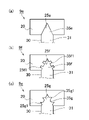
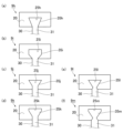
- FIGS. 6 to 8 are plan views of the concave-convex fitting structure 9.
- FIG. 6 to 8 are plan views of the concave-convex fitting structure 9.
- FIG. 6 The shape of the concave-convex fitting structure 9 described below is a shape viewed from above.
- the basic concave-convex fitting structure 9 is rectangular.
- the convex shape of the tooth convex portion 35a is rectangular, and the concave shape of the yoke concave portion 25a is rectangular.
- the concave-convex fitting structure 9b of FIG. 6(b) is a structure in which a smaller fitting structure is added to the concave-convex fitting structure 9a of FIG. 6(a).
- two small rectangular small protrusions 35b1 are provided on each of the left and right surfaces of the rectangular tooth protrusion 35b.
- two small rectangular recesses 25b1 are provided on each of the left and right surfaces of the yoke recess 25b. The small concave portion 25b1 and the small convex portion 35b1 are fitted.
- the concave-convex fitting structure 9c of FIG. 6(c) is a structure in which a smaller fitting structure is added to the upper side of the concave-convex fitting structure 9a of FIG.
- two small rectangular small protrusions 35c1 are provided on each of the left and right surfaces of the rectangular teeth protrusion 35c, and three small protrusions 35c2 are provided on the surface in the projecting direction.
- two small rectangular recesses 25c1 are provided on each of the left and right surfaces of the yoke recess 25c, and three small rectangular recesses 25c2 are provided on the recessed surface.
- the small protrusions 35c1 and 35c2 are fitted with the small recesses 25c1 and 25c2.
- the fitting structure 9a by forming the concave-convex fitting structure 9a into a rectangular concave-convex shape fitting, the fitting structure can be simplified, and the manufacturing cost can be reduced.
- the fitting accuracy that is, the fixing accuracy of the yoke 20 and the teeth 30 can be increased. Moreover, it is possible to prevent the teeth 30 from coming off to the rotor 2 side.
- the basic concave-convex fitting structure 9 is triangular.
- the convex shape of the tooth convex portion 35e is triangular, and the concave shape of the yoke concave portion 25e is triangular.
- the concave-convex fitting structure 9f of FIG. 7(b) is a structure in which a smaller fitting structure is added to the concave-convex fitting structure 9e of FIG. 7(a). Specifically, as shown in the drawing, two small rectangular small protrusions 35f1 are provided on each of the left and right surfaces of the triangular tooth protrusion 35f. In the yoke 20, two small rectangular recesses 25f1 are provided on each of the left and right surfaces of the yoke recess 25f. The small concave portion 25f1 and the small convex portion 35f1 are fitted.
- the fitting structure 9e As shown in FIG. 7(a), by forming the concave-convex fitting structure 9e into a rectangular concave-convex shape fitting, the fitting structure can be simplified, and the manufacturing cost can be reduced. Moreover, since the unevenness is triangular, fitting is easy. As shown in FIGS. 7B and 7C, by adding a small uneven fitting structure, the fitting accuracy, that is, the fixing accuracy of the yoke 20 and the teeth 30 can be increased. Moreover, it is possible to prevent the teeth 30 from coming off to the rotor 2 side.
- the basic concave-convex fitting structure 9 is wedge-shaped.
- the convex shape of the tooth convex portion 35h is a wedge shape that widens radially outward (projecting direction side).
- the concave shape of the yoke concave portion 25h is an inverted wedge shape that matches the wedge shape of the tooth convex portion 35h.
- the convex shape of the tooth convex portion 35i protrudes so as to widen from the tooth base portion 31 and becomes a rectangular shape with a constant width from the middle.
- the recessed shape of the yoke recessed portion 25i is gradually widened halfway so as to match the shape of the teeth protruded portion 35i, and becomes equal in width from the middle.
- the convex shape of the tooth convex portion 35j protrudes from the tooth base portion 31 with the same width, and the radially outer side (protruding direction side) becomes wider from the middle.
- the concave shape of the yoke concave portion 25j has a uniform width halfway so as to match the shape of the teeth convex portion 35j, and the radially outer side (protruding direction side) widens from the middle.
- the convex shape of the tooth convex portion 35k protrudes from the tooth base portion 31 with a uniform width, and the radially outer side (protruding direction side) becomes wide from the middle, and further the width becomes uniform from the middle. It's becoming
- the concave shape of the yoke concave portion 25k has a uniform width halfway so as to match the shape of the teeth convex portion 35k, the radially outer side (protruding direction side) becomes wider from the middle, and the width becomes uniform from the middle. It has become.
- the convex shape of the tooth convex portion 35l protrudes from the tooth base portion 31 so as to gradually become narrower, and is widened from the middle.
- the recessed shape of the yoke recessed portion 25l is formed so that the width gradually becomes narrower halfway so as to match the shape of the teeth projected portion 35l, and the width gradually widens from the middle.
- the convex shape of the tooth convex portion 35m protrudes from the tooth base portion 31 so as to gradually become narrower, gradually widens in the middle, and becomes equal in width from the middle.
- the concave shape of the yoke concave portion 25m is formed so that the width gradually narrows halfway so as to match the shape of the teeth convex portion 35m.
- FIG. 9 shows a concave-convex fitting structure 9n of a modification, in which the convex-concave fitting structure 9 (9a to 9m) described above is reversed. That is, the concave-convex fitting structure 9n is a structure in which the tooth concave portion 36 provided in the teeth 30 in a concave shape and the yoke convex portion 26 provided in the yoke 20 in a convex shape are fitted.
- the yoke convex portion 26 is formed in a wedge shape with a wider center side in the radial direction.
- the tooth recesses 36 are formed in an inverted wedge shape that matches the wedge shape of the yoke protrusions 26 .
- teeth 30 are prepared by laminating a plurality of magnetic steel sheets in the axial direction and fixing them in close contact.
- the tooth base 31 of the tooth 30 is covered with a thin first resin composition around the tooth base 31 by insert molding to form a tooth resin coating portion 37. is formed on the surface of the tooth base 31 .
- a method of manufacturing the yoke 20 will be described with particular attention to a method of forming the yoke resin coating portion 27 (yoke coating step) with reference to FIGS. 11 and 2 and 3 described above.
- a yoke 20 is prepared by laminating a plurality of magnetic steel sheets in the axial direction and fixing them in close contact.
- the surface of the yoke 20 on the slot side that is, the inner peripheral surface 23
- a covering portion 27 is formed.
- ⁇ Fitting Step (1) of Yoke 20 and Teeth 30> a method of manufacturing stator 10 will be described with particular focus on the step of fitting yoke 20 and teeth 30 (step of fixing teeth).
- a plurality of teeth 30 provided separately from the yoke 20 and having coils 50 wound around the cylindrical yoke 20 are fixed on the cylindrical inner peripheral surface 23 of the yoke 20 . Install so that it protrudes toward the direction center.
- a coil winding process of winding the coil 50 around the teeth 30 is included in the process prior to the teeth fixing process.
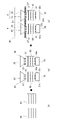
- Coil winding process As shown in FIG. 12(a), first, a wound coil 50 is prepared. At this time, the coil 50 is distributed winding or concentrated winding depending on the type of the motor 100 . Next, as shown in FIG. 12B, the teeth 30 provided with the tooth resin coating portions 37 in advance by the tooth resin coating step are prepared, and the teeth 30 are inserted into the holes of the coils 50 . At this time, the coil 50 is attached so as to wind around the tooth base 31 on which the tooth resin coating portion 37 is formed. If it is difficult to insert the teeth 30 into the holes of the coils 50 due to the shape of the teeth 30, the coils 50 may be wound around the teeth bases 31 by a coil winding device. In any case, the coil 50 is wound around the teeth 30 before the teeth 30 are fixed to the yoke 20 .
- Teeth fixing process Subsequently, as shown in FIG. 12(c), the tooth projections 35 of the teeth 30 around which the coils 50 are wound are attached to the yokes of the yoke 20 on which the yoke resin coating portion 27 is formed in advance by the yoke coating process. It fits into the recess 25 . As a result, the concave-convex fitting structure 9 in which the yoke 20 and the teeth 30 are fitted is obtained.
- the coils 50 are wound around a plurality of teeth 30 by distributed winding, in the teeth fixing step, the plurality of teeth 30 and the coils 50 formed as one unit by distributed winding are attached to the yoke 20 in unit units. can be done.
- the tooth convex portion 35 of the tooth 30 having the tooth resin coating portion 37 formed on the tooth base portion 31 is replaced with the yoke concave portion of the yoke 20 having the yoke resin coating portion 27 formed thereon. Fit in 25.
- a coil winding device is used to wind the coil 50 around the tooth base 31 on which the tooth resin coating portion 37 is formed.
- the method for manufacturing the stator 10 of this embodiment has the following features.
- the manufacturing method of the stator 10 includes a cylindrical yoke 20 and a plurality of teeth 30 which are provided separately from the yoke 20 and around which the coils 50 are wound. has a tooth fixing step of attaching so as to protrude toward the center in the radial direction, In the tooth 30, the region around which the coil 50 is wound (the tooth resin coating portion 37) is covered with the first cured product of the first resin composition. Since the separately provided yoke 20 and the teeth 30 are fitted together, the operation of providing the teeth resin coating portions 37 on the teeth 30 and winding the coils 50 is facilitated.
- a coil winding process of winding the coil 50 around the teeth 30 is included in the process preceding the teeth fixing process. Since the teeth 30 with the coils 50 wound thereon are prepared in advance and attached to the yoke 20 , damage to the teeth resin coating portions 37 during the process of winding the coils 50 can be suppressed.
- the coil winding step the coil 50 is wound around the plurality of teeth 30 by distributed winding.
- the teeth fixing step a plurality of teeth 30 and coils 50 formed as one unit by distributed winding are attached to the yoke 20 in unit units. Since a unit in which the coils 50 are distributed and wound around a plurality of teeth 30 is prepared in advance and attached to the yoke 20, the coil winding process is facilitated.
- the yoke 20 and the teeth 30 are fixed by the concave-convex fitting structure 9 . Thereby, the fixed state of the yoke 20 and the teeth 30 can be ensured.
- the concave-convex fitting structure 9 is a structure in which the yoke concave portion 25 provided in the yoke 20 in a concave shape and the tooth convex portion 35 provided in the tooth 30 in a convex shape are engaged. Thereby, the fixed state of the yoke 20 and the teeth 30 can be ensured.
- the yoke recesses 25 are formed in a wedge shape that narrows on the radial center side (rotor 2 side), and the tooth protrusions 35 are formed in a reverse wedge shape that matches the wedge shape of the yoke recesses 25 . ing. As a result, it is possible to prevent the teeth 30 from slipping out from the yoke 20 toward the center in the radial direction (toward the rotor 2).
- the concave-convex fitting structure 9 is a structure in which tooth concave portions 36 provided in the teeth 30 in a concave shape and yoke convex portions 26 provided in the yoke 20 in a convex shape are fitted.
- the yoke convex portion 26 is formed in a wedge shape with a wider radial center side,
- the tooth recesses 36 are formed in an inverted wedge shape that matches the wedge shape of the yoke protrusions 26 .
- the stator 10 of this embodiment has the following features.
- the stator 10 includes a cylindrical yoke 20, a plurality of teeth 30 provided separately from the yoke 20, attached to the yoke 20, and having a coil 50 wound thereon;
- the teeth 30 are attached to the cylindrical inner peripheral surface 23 of the yoke 20 so as to protrude toward the center in the radial direction.
- the tooth 30 has a region (the tooth base portion 31, the tooth resin coating portion 37) around which the coil 50 is wound, which is covered with a first cured product obtained by curing the first resin composition. (12)
- the glass transition temperature Tg of the resin (first resin composition) of the tooth resin coating portion 37, that is, the first cured product is 120° C. or higher.
- the motor 100 can be used at high temperatures. In addition, it is possible to cope with the increase in heat generated due to the increase in output of the motor 100 .
- the resin of the tooth resin coating portion 37 contains epoxy resin. This provides high heat resistance and insulation reliability.
- the first resin composition contains a filler as a filler. Thereby, the strength of the tooth resin coating portion 37 can be increased.
- the filler content of the first resin composition is 60% by volume or more. Thereby, the strength of the tooth resin coating portion 37 can be increased.
- the thermal conductivity of the first cured product is 0.5 W/mK or more.
- the yoke 20 has a region facing the slot 40 covered with a second cured product obtained by curing the second resin composition. That is, the region facing the slot 40 is configured as the yoke resin coating portion 27 coated with the second cured material. Insulation between the yoke 20 and the coil 50 can be ensured.
- the glass transition temperature Tg of the second resin composition (the second cured material forming the yoke resin coating portion 27) is 120°C or higher. By using a resin (especially a thermosetting resin) with a glass transition temperature Tg of 120° C. or higher, the motor 100 can be used at high temperatures.
- the second resin composition contains an epoxy resin. This provides high heat resistance and insulation reliability.
- the second resin composition contains a filler as a filler. Thereby, the strength of the yoke resin coating portion 27 can be increased.
- the filler content of the second resin composition is 60% by volume or more. Thereby, the strength of the yoke resin coating portion 27 can be increased.
- the thermal conductivity of the second cured product is 0.5 W/mK or more.
- the yoke 20 and the teeth 30 are fixed by the concave-convex fitting structure 9 (the yoke concave portions 25 and the tooth convex portions 35).
- the fixed state of the yoke 20 and the teeth 30 can be ensured.
- the concave-convex fitting structure 9 concavo-convex fitting structures 9a to 9m
- the yoke concave portion 25 provided in the yoke 20 in a concave shape and the tooth convex portion 35 provided in the tooth 30 in a convex shape are fitted. Structure. Thereby, the fixed state of the yoke 20 and the teeth 30 can be ensured.
- the yoke recess 25 is formed in a wedge shape that narrows toward the radial center side (that is, the rotor 2 side), and the tooth protrusion 35 is formed in a reverse wedge shape that matches the wedge shape of the yoke recess 25. It is Thereby, the fixed state of the yoke 20 and the teeth 30 can be ensured.
- the concave-convex fitting structure 9 (convex-convex fitting structure 9n) is a structure in which the tooth recesses 36 provided in the teeth 30 in a recessed manner and the yoke protrusions 26 provided in the yoke 20 in a protrusive manner are fitted. be.
- the yoke convex portion 26 is formed in a wedge shape with a radial center side widened, and the teeth concave portion 36 is formed in an inverted wedge shape that matches the wedge shape of the yoke convex portion 26 . As a result, it is possible to prevent the teeth 30 from slipping out of the yoke 20 toward the center of the shape.
Landscapes
- Engineering & Computer Science (AREA)
- Power Engineering (AREA)
- Manufacturing & Machinery (AREA)
- Manufacture Of Motors, Generators (AREA)
- Iron Core Of Rotating Electric Machines (AREA)
- Insulation, Fastening Of Motor, Generator Windings (AREA)
Priority Applications (1)
| Application Number | Priority Date | Filing Date | Title |
|---|---|---|---|
| JP2023514741A JP7311072B1 (ja) | 2021-09-15 | 2022-09-09 | ステータの製造方法、ステータ、ティース及びヨーク |
Applications Claiming Priority (2)
| Application Number | Priority Date | Filing Date | Title |
|---|---|---|---|
| JP2021150025 | 2021-09-15 | ||
| JP2021-150025 | 2021-09-15 |
Publications (1)
| Publication Number | Publication Date |
|---|---|
| WO2023042760A1 true WO2023042760A1 (ja) | 2023-03-23 |
Family
ID=85602174
Family Applications (1)
| Application Number | Title | Priority Date | Filing Date |
|---|---|---|---|
| PCT/JP2022/033863 Ceased WO2023042760A1 (ja) | 2021-09-15 | 2022-09-09 | ステータの製造方法、ステータ、ティース及びヨーク |
Country Status (2)
| Country | Link |
|---|---|
| JP (1) | JP7311072B1 (https=) |
| WO (1) | WO2023042760A1 (https=) |
Citations (4)
| Publication number | Priority date | Publication date | Assignee | Title |
|---|---|---|---|---|
| JP2009254133A (ja) * | 2008-04-07 | 2009-10-29 | Mitsubishi Electric Corp | エレベータのモータ及びエレベータ装置 |
| JP2011244674A (ja) * | 2010-05-21 | 2011-12-01 | Ihi Corp | 分割型ステータ |
| JP2012105420A (ja) * | 2010-11-09 | 2012-05-31 | Mitsubishi Electric Corp | モータの絶縁構造及びその製造方法 |
| JP2021040483A (ja) * | 2017-02-13 | 2021-03-11 | 株式会社三井ハイテック | 固定子積層鉄心の製造方法及び固定子積層鉄心 |
-
2022
- 2022-09-09 JP JP2023514741A patent/JP7311072B1/ja active Active
- 2022-09-09 WO PCT/JP2022/033863 patent/WO2023042760A1/ja not_active Ceased
Patent Citations (4)
| Publication number | Priority date | Publication date | Assignee | Title |
|---|---|---|---|---|
| JP2009254133A (ja) * | 2008-04-07 | 2009-10-29 | Mitsubishi Electric Corp | エレベータのモータ及びエレベータ装置 |
| JP2011244674A (ja) * | 2010-05-21 | 2011-12-01 | Ihi Corp | 分割型ステータ |
| JP2012105420A (ja) * | 2010-11-09 | 2012-05-31 | Mitsubishi Electric Corp | モータの絶縁構造及びその製造方法 |
| JP2021040483A (ja) * | 2017-02-13 | 2021-03-11 | 株式会社三井ハイテック | 固定子積層鉄心の製造方法及び固定子積層鉄心 |
Also Published As
| Publication number | Publication date |
|---|---|
| JP7311072B1 (ja) | 2023-07-19 |
| JPWO2023042760A1 (https=) | 2023-03-23 |
Similar Documents
| Publication | Publication Date | Title |
|---|---|---|
| US7939975B2 (en) | Over-mold stator assembly and process for preparation thereof | |
| JP6373854B2 (ja) | ステータ又はロータ | |
| US20240006947A1 (en) | Stator, rotating electric machine, and method of manufacturing stator | |
| EP4387057A1 (en) | Rotor for an axial flux motor | |
| CN101282066A (zh) | 旋转电机线圈部的绝缘结构 | |
| JP7311072B1 (ja) | ステータの製造方法、ステータ、ティース及びヨーク | |
| JP7375984B2 (ja) | 金型及び樹脂層形成方法 | |
| JP2022092163A (ja) | 電動機用ステータおよび電動機 | |
| JP5284847B2 (ja) | 電動機用ステータ又はロータの製造方法 | |
| CN114830508A (zh) | 定子用散热盖、包括该散热盖的定子组件及马达 | |
| JP2024123482A (ja) | ステータの製造方法 | |
| JP7608804B2 (ja) | 構造体 | |
| JP2013138611A (ja) | ロータに用いる固定用樹脂組成物 | |
| WO2025197744A1 (ja) | ステータの製造方法 | |
| JP2022149379A (ja) | ステータおよび回転電機 | |
| JP2025019635A (ja) | ステータの製造方法、ステータおよび金型 | |
| JP2024123480A (ja) | バスバー基板、バスバー基板装置およびステータ | |
| WO2024181529A1 (ja) | バスバー基板、バスバー基板装置、ステータおよびステータの製造方法 | |
| CN105471151B (zh) | 端部平面化的波纹弹簧和硬化定子线棒护面 | |
| WO2025115769A1 (ja) | 熱硬化性樹脂組成物およびステータの製造方法 | |
| JP7754372B2 (ja) | 構造体、インバータモジュール、モータ、および構造体の製造方法 | |
| JP2025119722A (ja) | ロータ、回転電機、およびロータの製造方法 | |
| JP2010239707A (ja) | 電動機用ステータ又はロータとその製造方法 | |
| JP2024126132A (ja) | 樹脂組成物およびロータ | |
| JP2022148598A (ja) | ステータおよびステータの製造方法 |
Legal Events
| Date | Code | Title | Description |
|---|---|---|---|
| WWE | Wipo information: entry into national phase |
Ref document number: 2023514741 Country of ref document: JP |
|
| 121 | Ep: the epo has been informed by wipo that ep was designated in this application |
Ref document number: 22869907 Country of ref document: EP Kind code of ref document: A1 |
|
| NENP | Non-entry into the national phase |
Ref country code: DE |
|
| 122 | Ep: pct application non-entry in european phase |
Ref document number: 22869907 Country of ref document: EP Kind code of ref document: A1 |