WO2023042575A1 - 状態推定システム、ダンプトラック、及び状態推定方法 - Google Patents
状態推定システム、ダンプトラック、及び状態推定方法 Download PDFInfo
- Publication number
- WO2023042575A1 WO2023042575A1 PCT/JP2022/030363 JP2022030363W WO2023042575A1 WO 2023042575 A1 WO2023042575 A1 WO 2023042575A1 JP 2022030363 W JP2022030363 W JP 2022030363W WO 2023042575 A1 WO2023042575 A1 WO 2023042575A1
- Authority
- WO
- WIPO (PCT)
- Prior art keywords
- exhaust gas
- temperature
- cargo
- dump
- flow rate
- Prior art date
- Legal status (The legal status is an assumption and is not a legal conclusion. Google has not performed a legal analysis and makes no representation as to the accuracy of the status listed.)
- Ceased
Links
Images




Classifications
-
- G—PHYSICS
- G07—CHECKING-DEVICES
- G07C—TIME OR ATTENDANCE REGISTERS; REGISTERING OR INDICATING THE WORKING OF MACHINES; GENERATING RANDOM NUMBERS; VOTING OR LOTTERY APPARATUS; ARRANGEMENTS, SYSTEMS OR APPARATUS FOR CHECKING NOT PROVIDED FOR ELSEWHERE
- G07C5/00—Registering or indicating the working of vehicles
- G07C5/08—Registering or indicating performance data other than driving, working, idle, or waiting time, with or without registering driving, working, idle or waiting time
- G07C5/0816—Indicating performance data, e.g. occurrence of a malfunction
- G07C5/0825—Indicating performance data, e.g. occurrence of a malfunction using optical means
-
- B—PERFORMING OPERATIONS; TRANSPORTING
- B60—VEHICLES IN GENERAL
- B60P—VEHICLES ADAPTED FOR LOAD TRANSPORTATION OR TO TRANSPORT, TO CARRY, OR TO COMPRISE SPECIAL LOADS OR OBJECTS
- B60P1/00—Vehicles predominantly for transporting loads and modified to facilitate loading, consolidating the load, or unloading
- B60P1/04—Vehicles predominantly for transporting loads and modified to facilitate loading, consolidating the load, or unloading with a tipping movement of load-transporting element
- B60P1/28—Tipping body constructions
-
- B—PERFORMING OPERATIONS; TRANSPORTING
- B60—VEHICLES IN GENERAL
- B60P—VEHICLES ADAPTED FOR LOAD TRANSPORTATION OR TO TRANSPORT, TO CARRY, OR TO COMPRISE SPECIAL LOADS OR OBJECTS
- B60P1/00—Vehicles predominantly for transporting loads and modified to facilitate loading, consolidating the load, or unloading
- B60P1/04—Vehicles predominantly for transporting loads and modified to facilitate loading, consolidating the load, or unloading with a tipping movement of load-transporting element
-
- G—PHYSICS
- G01—MEASURING; TESTING
- G01G—WEIGHING
- G01G19/00—Weighing apparatus or methods adapted for special purposes not provided for in the preceding groups
- G01G19/08—Weighing apparatus or methods adapted for special purposes not provided for in the preceding groups for incorporation in vehicles
Definitions
- the present disclosure relates to a state estimation system, a dump truck, and a state estimation method.
- a dump truck has a dump body on which cargo is loaded.
- the dump truck When discharging a load from a dump body, the dump truck performs a dump operation of the dump body. When a dump operation is performed, gravity ejects the load from the dump body. If the load is wet, at least a portion of the load may remain attached to the interior surface of the dump body and may not be ejected from the dump body when a dump operation is performed.
- BACKGROUND ART In order to prevent cargo from adhering to the inner surface of a dump body, a technique is known in which exhaust gas discharged from a dump truck engine is circulated through a channel provided in the dump body.
- Patent Literature 1 discloses a technique for heating a dump body.
- the purpose of the present disclosure is to obtain the temperature of the inner surface of the dump body.
- a state estimation system for a dump truck including an engine and a dump body having a flow path through which exhaust gas discharged from the engine flows and on which a load is loaded, wherein the flow rate of the exhaust gas flowing into the flow path is Based on the exhaust gas flow rate and the exhaust gas temperature, an exhaust gas flow rate acquisition unit that acquires the exhaust gas flow rate that indicates the detection data of the exhaust gas flow rate acquisition unit that acquires the exhaust gas temperature that indicates the detection data of the temperature of the exhaust gas flowing into the flow path, a body temperature estimator for estimating a body temperature indicative of the temperature of a predetermined portion of the interior surface of the dump body in contact with a load.
- the temperature of the inner surface of the dump body is acquired.
- FIG. 1 is a side view showing the dump truck according to the embodiment.
- FIG. 2 is a perspective view showing the dump body according to the embodiment.
- FIG. 3 is a diagram schematically showing the dump truck according to the embodiment.
- FIG. 4 is a diagram showing the inside of the cab according to the embodiment.
- FIG. 5 is a schematic diagram of a work site where the dump truck according to the embodiment operates.
- FIG. 6 is a functional block diagram showing the state estimation system according to the embodiment.
- FIG. 7 is a diagram for explaining predetermined portions of the inner surface of the dump body according to the embodiment.
- FIG. 8 is a flow chart showing a state estimation method according to an embodiment.
- FIG. 9 is a block diagram showing a computer system according to the embodiment.
- FIG. 1 is a side view showing a dump truck 1 according to an embodiment.
- the dump truck 1 is a manned dump truck operated by a driver's driving operation.
- the dump truck 1 is a rigid frame type dump truck.
- the dump truck 1 includes a vehicle body 2, a travel device 3, an engine 6, a dump body 10, and a hoist cylinder 7.
- the vehicle body 2 supports the dump body 10.
- a cab 9 is provided on the upper front portion of the vehicle body 2 .
- a driver of the dump truck 1 rides inside the cab 9 .
- the traveling device 3 supports the vehicle body 2 and travels.
- the travel device 3 has a plurality of wheels 4 .
- the wheels 4 on the front side are steering wheels.
- the rear wheels 4 are drive wheels.
- a tire 5 is attached to each of the plurality of wheels 4 .
- the dump truck 1 travels as the wheels 4 rotate.
- the engine 6 is the power source of the dump truck 1. Each of the traveling device 3 and the hoist cylinder 7 operates based on the power generated by the engine 6 .
- the engine 6 is supported by at least part of the vehicle body 2 .
- Engine 6 is an internal combustion engine. A diesel engine is exemplified as the engine 6 .
- the engine 6 burns fuel to generate power. Exhaust gas is discharged from the engine 6 by burning the fuel.
- the dump body 10 is loaded with cargo. Earth and sand are exemplified as the cargo loaded on the dump body 10 .
- a lower portion of the rear portion of the dump body 10 is connected to a bracket 8 of the vehicle body 2 via a rotating pin 8P.
- the dump body 10 is rotatable around the rotation pin 8P.
- the hoist cylinder 7 generates power to rotate the dump body 10 .
- a hoist cylinder is a hydraulic cylinder.
- the hoist cylinder 7 is arranged between the vehicle body 2 and the dump body 10 .
- the dump body 10 changes between a loading posture and a standing posture due to the expansion and contraction of the hoist cylinder 7.
- the loading posture refers to a posture in which the dump body 10 is lowered so as to be closest to the vehicle body 2 within the movable range.
- the standing posture refers to a posture in which the dump body 10 is raised so as to be the most separated from the vehicle body 2 within the movable range.
- a load is loaded on the dump body 10 when the dump body 10 is in the loading posture.
- the dump truck 1 travels when the dump body 10 is in the loading attitude.
- the operation of changing the dump body 10 from the loading posture to the standing posture while the load is loaded on the dump body 10 is appropriately referred to as a dumping motion.
- the cargo is discharged from the dump body 10 by performing the dump operation of the dump body 10 .
- the dumping operation of the dumping body 10 includes the operation of rotating the dumping body 10 backward. That is, in the embodiment, the dump body 10 discharges the cargo rearward by a rear dump method.
- FIG. 2 is a perspective view showing the dump body 10 according to the embodiment.
- the dump body 10 includes a front plate 11, a bottom plate 12 connected to the lower end of the front plate 11, and connected to the left and right ends of the front plate 11 and the left and right ends of the bottom plate 12. and a protector plate 14 connected to the upper end of the front plate 11 .
- the front plate 11, bottom plate 12, side plate 13, and protector plate 14 are integrated.
- Each of the front plate 11, bottom plate 12, side plate 13, and protector plate 14 is made of a steel material.
- the protector plate 14 is arranged above the cab 9 when the dump body 10 is in the loading posture. A rear end portion of the protector plate 14 and an upper end portion of the front plate 11 are connected. A lower end portion of the front plate 11 and a front end portion of the bottom plate 12 are connected.
- the side plates 13 are arranged on the right and left sides of the center of the dump body 10 in the left-right direction.
- the side plate 13 is arranged on the right side of the center of the dump body 10, and is arranged on the left side of the center of the dump body 10.
- a left side plate 13L connected to the left end of the front plate 11 and the left end of the bottom plate 12, respectively.
- the front plate 11 has a front surface facing forward and a rear surface facing in the direction opposite to the front surface.
- the bottom plate 12 has a bottom surface facing upward and a lower surface facing in the direction opposite to the bottom surface.
- the side plate 13 has an inner surface facing the center of the dump body 10 and an outer surface facing in the direction opposite to the inner surface in the left-right direction.
- a loading space in which cargo is loaded is defined between the rear surface of the front plate 11 , the bottom surface of the bottom plate 12 and the inner surface of the side plate 13 .
- the load contacts at least a portion of the rear surface of the front plate 11 , the bottom surface of the bottom plate 12 and the inner surface of the side plates 13 .
- the rear surface of the front plate 11 of the dump body 10, the bottom surface of the bottom plate 12, and the inner surface of the side plate 13, which come into contact with the cargo are collectively referred to as the inner surface of the dump body 10 as appropriate.
- the dump body 10 has an inlet 21 through which the exhaust gas discharged from the engine 6 is introduced, a flow path 23 through which the exhaust gas discharged from the engine 6 flows, and an exhaust port 22 through which the exhaust gas that has flowed through the flow path 23 is discharged. and
- the introduction port 21 side is synonymous with the upstream side of the exhaust gas
- the exhaust port 22 side is synonymous with the downstream side of the exhaust gas.
- the introduction port 21 is provided on the front surface of the front plate 11 .
- the introduction port 21 is provided on the upper right portion of the front surface of the front plate 11 .
- the introduction port 21 may be provided in the central portion of the front surface in the left-right direction.
- the vehicle body 2 has a conduit that guides the exhaust gas discharged from the engine 6 to the inlet 21 .
- the outlet of the conduit and the introduction port 21 are connected when the dump body 10 is in the loading posture. Exhaust gas discharged from the engine 6 is supplied to the introduction port 21 when the dump body 10 is in the loading posture.
- the outlet of the conduit and the inlet 21 are separated from each other.
- the exhaust gas discharged from the engine 6 is discharged from the outlet of the conduit.
- the exhaust port 22 is provided on the bottom surface of the bottom plate 12 .
- the exhaust port 22 is provided at the rear portion of the lower surface of the bottom plate 12 .
- the exhaust port 22 may be provided at the rear portion of the side plate 13 .
- the flow path 23 is provided inside the dump body 10 . At least part of the channel 23 is provided in the side plate 13 . Exhaust gas discharged from the engine 6 flows into the flow path 23 from the inlet 21 . Exhaust gas that has flowed through the flow path 23 is discharged from the exhaust port 22 .
- the flow passages 23 are provided at a first flow passage 23A provided at the upper end portion of the right side plate 13R, a second flow passage 23B provided at the boundary between the front plate 11 and the right side plate 13R, and a lower end portion of the right side plate 13R.
- It includes a sixth flow path 23F provided at the upper end and a seventh flow path 23G provided at the lower end of the left side plate 13L.
- Each of the upper end and lower end of the right side plate 13R includes strength members such as ribs.
- Each of the upper and lower ends of the left side plate 13L includes strength members such as ribs.
- the first flow path 23A, the third flow path 23C, the sixth flow path 23F, and the seventh flow path 23G are provided in the strength member of the dump body 10. As shown in FIG.
- the first flow path 23A extends in the front-rear direction at the upper end portion of the right side plate 13R.
- 23 A of 1st flow paths may incline with respect to the front-back direction.
- a front end portion of the first flow path 23A is connected to the inlet 21 . Exhaust gas that has flowed into the first flow path 23A from the inlet 21 flows through the first flow path 23A toward the rear end portion of the first flow path 23A.
- the second flow path 23B is provided at the boundary between the front plate 11 and the right side plate 13R.
- the second flow path 23B slopes downward and rearward.
- An upper end portion of the second flow path 23B is connected to the inlet 21 .
- the exhaust gas that has flowed into the second flow path 23B from the inlet 21 flows through the second flow path 23B toward the lower end portion of the second flow path 23B.
- the third flow path 23C is provided at the lower end of the right side plate 13R. 23 C of 3rd flow paths incline upward toward back. A front end portion of the third flow path 23C is connected to a lower end portion of the second flow path 23B. Exhaust gas that has flowed into the third flow path 23C from the second flow path 23B flows through the third flow path 23C toward the rear end portion of the third flow path 23C.
- the fourth flow path 23D extends in the left-right direction at the boundary between the front plate 11 and the bottom plate 12. A right end portion of the fourth flow path 23D is connected to a lower end portion of the second flow path 23B. Exhaust gas that has flowed into the fourth flow path 23D from the second flow path 23B flows through the fourth flow path 23D toward the left end of the fourth flow path 23D.
- the fifth flow path 23E is provided at the boundary between the front plate 11 and the left side plate 13L.
- the fifth flow path 23E slopes upward and forward.
- a lower end portion of the fifth flow path 23E is connected to a left end portion of the fourth flow path 23D. Exhaust gas that has flowed into the fifth flow path 23E from the fourth flow path 23D flows through the fifth flow path 23E toward the upper end portion of the fifth flow path 23E.
- the sixth flow path 23F extends in the front-rear direction at the upper end of the left side plate 13L.
- the sixth flow path 23F may be inclined with respect to the front-rear direction.
- a front end portion of the sixth flow path 23F is connected to an upper end portion of the fifth flow path 23E. Exhaust gas that has flowed into the sixth flow path 23F from the fifth flow path 23E flows through the sixth flow path 23F toward the rear end portion of the sixth flow path 23F.
- the seventh flow path 23G is provided at the lower end of the left side plate 13L.
- the seventh flow path 23G is inclined upward toward the rear.
- a front end portion of the seventh flow path 23G is connected to a left end portion of the fourth flow path 23D.
- the exhaust gas that has flowed into the seventh flow path 23G from the fourth flow path 23D flows through the seventh flow path 23G toward the rear end portion of the seventh flow path 23G.
- the rear end of the first channel 23A, the rear end of the third channel 23C, the rear end of the sixth channel 23F, and the rear end of the seventh channel 23G are provided on the lower surface of the bottom plate 12. It is connected to the exhaust port 22 via the flow path provided. Exhaust gas that has flowed through the flow path 23 is discharged below the bottom plate 12 through the exhaust port 22 .
- the exhaust gas supplied from the engine 6 to the inlet 21 is branched into the first flow path 23A and the second flow path 23B. As a result, the exhaust resistance of the engine 6 is reduced, and deterioration of the fuel consumption rate of the engine 6 is suppressed.
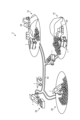
- FIG. 3 is a diagram schematically showing the dump truck 1 according to the embodiment.
- the dump truck 1 includes an engine 6, a conduit 24, an aftertreatment device 15, a conduit 25, a dump body 10, an exhaust gas flow sensor 16, an exhaust gas temperature sensor 17, and an outside air temperature sensor. 18 , a cargo weight sensor 19 , a controller 60 and an output device 35 .
- the conduit 24 connects the exhaust gas outlet 6B of the engine 6 and the exhaust gas inlet 15A of the aftertreatment device 15 .
- the exhaust gas discharged from the exhaust gas outlet 6B of the engine 6 flows through the conduit 24 and is supplied to the aftertreatment device 15 .
- the post-treatment device 15 purifies the exhaust gas discharged from the engine 6.
- a urea SCR (Selective Catalytic Reduction) system that reduces and purifies nitrogen oxides (NOx) contained in the exhaust gas using a selective catalyst and a reducing agent is exemplified.
- the conduit 25 connects the exhaust gas outlet 15B of the aftertreatment device 15 and the introduction port 21 of the dump body 10 .
- the exhaust gas discharged from the exhaust gas outlet 15 ⁇ /b>B of the aftertreatment device 15 flows through the conduit 25 and is supplied to the flow path 23 of the dump body 10 .
- Exhaust gas discharged from the post-treatment device 15 and flowing into the flow path 23 through the inlet 21 is discharged from the exhaust port 22 after flowing through the flow path 23 .
- the exhaust gas flow rate sensor 16 detects the flow rate of exhaust gas flowing into the flow path 23 of the dump body 10 .
- the exhaust gas flow rate sensor 16 is arranged near the exhaust gas outlet 6B of the engine 6 and detects the flow rate of the exhaust gas flowing out from the exhaust gas outlet 6B of the engine 6 .
- the exhaust gas flow rate sensor 16 may be arranged in the middle of the conduit 24, may be arranged near the exhaust gas inlet 15A of the post-treatment device 15, or may be arranged near the exhaust gas outlet 15B of the post-treatment device 15. It may be positioned or may be positioned in the middle of conduit 25 .
- the exhaust gas flow rate sensor 16 may be arranged near the introduction port 21 of the dump body 10 and detect the flow rate of the exhaust gas flowing into the introduction port 21 .
- the exhaust gas temperature sensor 17 detects the temperature of exhaust gas flowing into the flow path 23 of the dump body 10 .
- the exhaust gas temperature sensor 17 is arranged near the introduction port 21 of the dump body 10 and detects the temperature of the exhaust gas flowing into the introduction port 21 .
- the exhaust gas temperature sensor 17 may be arranged near the exhaust gas outlet 6B of the engine 6 to detect the temperature of the exhaust gas flowing out from the engine 6 .
- the exhaust gas temperature sensor 17 may be arranged in the middle of the conduit 24, may be arranged near the exhaust gas inlet 15A of the aftertreatment device 15, or may be arranged near the exhaust gas outlet 15B of the aftertreatment device 15. , or may be located in the middle of the conduit 25 .
- the outside air temperature sensor 18 detects the temperature of outside air around the dump body 10 .
- the outside air temperature sensor 18 is arranged, for example, in the upper portion of the vehicle body 2 . Before the exhaust gas is supplied to the flow path 23 of the dump body 10, the temperature of the outside air and the temperature of the dump body 10 are substantially equal. By detecting the temperature of the outside air, the outside air temperature sensor 18 can detect the temperature of the dump body 10 before exhaust gas is supplied to the flow path 23 .
- the cargo weight sensor 19 detects the weight of cargo loaded on the dump body 10 .
- the travel device 3 has suspension cylinders that support the rear wheels 4 .
- the payload sensor 19 is located on the suspension cylinder.
- the weight of the dump body 10 is known data.
- the cargo weight sensor 19 can detect the weight of cargo loaded on the dump body 10 by detecting the weight of the dump body 10 .
- the controller 60 includes a computer system. Controller 60 is mounted on vehicle body 2 .
- the output device 35 outputs predetermined output data.
- the output device 35 is arranged inside the cab 9 .
- the output device 35 provides output data to the driver in the cab 9 .
- output device 35 includes a display device.
- the display device displays display data as output data.
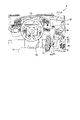
- FIG. 4 is a diagram showing the inside of the cab 9 according to the embodiment. As shown in FIG. 4, inside the cab 9, a driver's seat 31, a steering wheel 32, an accelerator pedal 33, a brake pedal 34, an output device 35, and an operation device 40 are arranged.
- a cigarette lighter 36, a power window switch 37, a side lamp switch 38, and an option switch 39 are arranged on the right side of the operating device 40.
- a fog lamp switch or a revolving lamp switch is exemplified as the option switch 39 .
- the driver of the dump truck 1 sits on the driver's seat 31.
- the steering wheel 32 is operated by the driver to change the traveling direction of the dump truck 1 .
- the front wheels 4 are steered by operating the steering wheel 32 .
- the accelerator pedal 33 is operated by the driver to accelerate the traveling device 3 .
- the brake pedal 34 is operated by the driver to decelerate or stop the traveling device 3 .
- the output device 35 provides predetermined output data to the driver.
- Output device 35 includes a display device that displays display data as output data.
- the output device 35 includes a display 71 for displaying display data and a display controller 72 .
- the display 71 includes a flat panel display such as a liquid crystal display (LCD) or an organic electroluminescence display (OELD).
- the operating device 40 is operated by the driver.
- the operating device 40 includes a shift lever 42 , a hoist switch 43 , a parking brake switch 44 and a hoist switch lock knob 45 .
- the shift lever 42 is operated to change the speed stages of the travel device 3 . Further, the shift lever 42 is operated to switch the dump truck 1 between forward and reverse.
- a hoist switch 43 is operated to drive the hoist cylinder 7 . By operating the hoist switch 43, the dump body 10 is dumped.
- the parking brake switch 44 is operated to operate the parking brake of the dump truck 1 .
- a hoist switch lock knob 45 is operated to disable the hoist switch 43 .
- FIG. 5 is a diagram schematically showing a work site 50 where the dump truck 1 according to the embodiment operates.
- the dump truck 1 is a self-propelled off-road dump truck that operates at a work site 50 .
- worksite 50 is a mine.
- a mine is an establishment where minerals are extracted.
- the work site 50 has a loading area 51 , an unloading area 52 , and a transport path 53 .
- the loading yard 51 is an area where a loader 54 such as a hydraulic excavator performs a loading operation for loading the dump body 10 of the dump truck 1 .
- the unloading site 52 is an area where the dump truck 1 performs unloading work for discharging the load from the dump body 10 .
- the transport path 53 is a path of the dump truck 1 that connects the loading site 51 and the dumping site 52 . The dump truck 1 travels along the transport path 53 so as to reciprocate between the loading site 51 and the dumping site 52 .
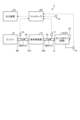
- FIG. 6 is a functional block diagram showing the state estimation system 100 according to the embodiment.
- a state estimation system 100 is mounted on a dump truck 1 .
- the state estimation system 100 estimates a body temperature Te, which indicates the temperature of a predetermined portion MP of the inner surface of the dump body 10 that contacts the cargo, based on the detection data of the exhaust gas flow rate sensor 16 and the detection data of the exhaust gas temperature sensor 17 .
- the state estimation system 100 also determines whether the dumping operation of the dumping body 10 is appropriate based on the estimated body temperature Te.
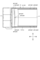
- FIG. 7 is a diagram for explaining a predetermined portion MP on the inner surface of the dump body 10 according to the embodiment.
- the loading space in which the load is loaded is defined between the rear surface of the front plate 11 , the bottom surface of the bottom plate 12 and the inner surfaces of the side plates 13 .
- the inner surface of the dump body 10 that contacts the load includes the rear surface of the front plate 11 , the bottom surface of the bottom plate 12 and the inner surface of the side plate 13 .
- the predetermined portion MP is a temperature estimation point whose temperature is estimated by the state estimation system 100 on the inner surface of the dump body 10 .
- a plurality of predetermined portions MP are defined on the inner surface of the dump body 10 . As shown in FIG. 7 , in the embodiment, the predetermined parts MP are defined at ten points on the inner surface of the dump body 10 . At least some of the plurality of predetermined portions MP are defined in the vicinity of the channel 23 .
- each of the first predetermined portion MP1, the second predetermined portion MP2, and the third predetermined portion MP3 is defined at the upper end portion of the front panel 11.
- the first predetermined portion MP1 is defined at the right end of the front plate 11
- the second predetermined portion MP2 is defined at the center of the front plate 11
- the third predetermined portion MP3 is defined at the left end of the front plate 11. specified in the Part.
- a fourth predetermined portion MP4 is defined at the right end of the front plate 11
- the fifth predetermined portion MP5 is defined at the center of the front plate 11
- the sixth predetermined portion MP6 is defined at the left end of the front plate 11. specified in the Part.
- a seventh predetermined portion MP7 and an eighth predetermined portion MP8 are defined at the lower end portion of the right side plate 13R.
- the seventh predetermined portion MP7 is defined in the central portion of the right side plate 13R
- the eighth predetermined portion MP8 is defined in the rear portion of the right side plate 13R.
- a ninth predetermined portion MP9 and a tenth predetermined portion MP10 are each defined at the lower end portion of the left side plate 13L.
- the ninth predetermined portion MP9 is defined in the central portion of the left side plate 13L
- the tenth predetermined portion MP10 is defined in the rear portion of the left side plate 13L.
- predetermined portions MP need not be defined at ten locations on the inner surface of the dump body 10, and may be defined at arbitrary multiple locations.
- the state estimation system 100 has an exhaust gas flow rate sensor 16, an exhaust gas temperature sensor 17, an outside air temperature sensor 18, a cargo weight sensor 19, a controller 60, and an output device 35.
- the controller 60 includes a body characteristic storage unit 61, a cargo characteristic storage unit 62, an exhaust gas flow rate acquiring unit 63, an exhaust gas temperature acquiring unit 64, an outside air temperature acquiring unit 65, a cargo weight acquiring unit 66, and a body temperature estimating unit. 67 , a loading state estimation unit 68 , and a dumping suitability determination unit 69 .
- the output device 35 has a display 71 and a display controller 72 .
- the display controller 72 has a body temperature display section 73 and a dump suitability display section 74 .
- the body characteristic storage unit 61 stores body characteristics Cb that indicate the characteristics of the dump body 10 .
- body characteristics Cb the shape of the dump body 10, the dimensions of the dump body 10, the material of the dump body 10, and the thermal characteristics of the dump body 10 are exemplified.
- thermal characteristics of the dump body 10 the heat capacity of the dump body 10 and the heat transfer coefficient of the dump body 10 are exemplified.
- the body characteristic Cb is known data known from the specifications of the dump truck 1 .
- the body characteristics Cb are pre-stored in the body characteristics storage unit 61 .
- the cargo characteristics storage unit 62 stores cargo characteristics Cs that indicate the characteristics of the cargo loaded on the dump body 10 .
- the cargo includes dirt.
- cargo characteristics Cs include the cargo material characteristics (soil quality), the cargo moisture content (wetness), and the cargo temperature.
- the material properties of the cargo are exemplified by cargo composition and cargo specific gravity.
- the cargo characteristic Cs is known data obtained from a preliminary survey of the loading area 51 .
- the cargo characteristic Cs is pre-stored in the cargo characteristic storage unit 62 .
- the cargo characteristics Cs may be set for each loading field 51 and stored in the cargo characteristics storage unit 62 . Further, the cargo characteristic Cs may be transmitted from the management computer of the control facility and stored in the cargo characteristic storage unit 62 each time the vehicle heads for a different loading area 51 .
- the exhaust gas flow rate acquisition unit 63 acquires detection data of the exhaust gas flow rate sensor 16 .
- the exhaust gas flow rate sensor 16 detects the flow rate of exhaust gas flowing into the flow path 23 of the dump body 10 .
- the exhaust gas flow rate acquisition unit 63 acquires an exhaust gas flow rate Df indicating detection data of the flow rate of the exhaust gas flowing into the flow path 23 of the dump body 10 detected by the exhaust gas flow rate sensor 16 .
- the exhaust gas temperature acquisition unit 64 acquires detection data from the exhaust gas temperature sensor 17 .
- the exhaust gas temperature sensor 17 detects the temperature of exhaust gas flowing into the flow path 23 of the dump body 10 .
- the exhaust gas temperature acquisition unit 64 acquires an exhaust gas temperature Dt indicating detection data of the temperature of the exhaust gas flowing into the flow path 23 of the dump body 10 detected by the exhaust gas temperature sensor 17 .
- the exhaust gas temperature Dt is, for example, 400[°C].
- the outside air temperature acquisition unit 65 acquires detection data from the outside air temperature sensor 18 .
- the outside air temperature sensor 18 detects the temperature of outside air around the dump body 10 .
- the outside air temperature acquisition unit 65 acquires an outside air temperature Do indicating detection data of the outside air temperature around the dump body 10 detected by the outside air temperature sensor 18 .
- the cargo weight acquisition unit 66 acquires the detection data of the cargo weight sensor 19 .
- the cargo weight sensor 19 detects the weight of cargo loaded on the dump body 10 .
- the cargo weight acquisition unit 66 acquires the cargo weight Da indicating detection data of the weight of the cargo loaded on the dump body 10 detected by the cargo weight sensor 19 .
- the body temperature estimator 67 estimates a body temperature Te that indicates the temperature of a predetermined portion MP of the inner surface of the dump body 10 that contacts the cargo. As described with reference to FIG. 7 , a plurality of predetermined parts MP are defined on the inner surface of the dump body 10 . Body temperature estimation unit 67 estimates body temperature Te of each of a plurality of predetermined parts MP.
- the body temperature estimator 67 has correlation data (map data) of the exhaust gas flow rate Df, the exhaust gas temperature Dt, and the body temperature Te. Correlation data can be created based on prior experiments or simulations.
- the body temperature estimator 67 can estimate the body temperature Te by collating the exhaust gas flow rate Df detected by the exhaust gas flow rate sensor 16 and the exhaust gas temperature Dt detected by the exhaust gas temperature sensor 17 with the correlation data. If the correlation data is discrete data, the body temperature Te may be estimated by interpolation.
- the body temperature estimating section 67 numerically analyzes the simulation model of the dump body 10 based on the exhaust gas flow rate Df and the exhaust gas temperature Dt.
- the body temperature Te may be estimated by implementation.
- the body temperature estimator 67 also estimates the required time Pr until the body temperature Te reaches the specified temperature Tp based on the exhaust gas flow rate Df and the exhaust gas temperature Dt.
- the prescribed temperature Tp related to the body temperature Te is, for example, 120 [°C].
- the body temperature estimator 67 estimates the required time Pr for the body temperature Te to reach 120[°C] from 30[°C].
- the body temperature estimator 67 has correlation data (map data) of the exhaust gas flow rate Df, the exhaust gas temperature Dt, the body temperature Te, and the required time Pr. Correlation data can be created based on prior experiments or simulations. The body temperature estimator 67 can estimate the required time Pr by collating the exhaust gas flow rate Df detected by the exhaust gas flow rate sensor 16 and the exhaust gas temperature Dt detected by the exhaust gas temperature sensor 17 with the correlation data.
- the body temperature estimating section 67 numerically analyzes the simulation model of the dump body 10 based on the exhaust gas flow rate Df and the exhaust gas temperature Dt.
- the required time Pr may be estimated by implementation.
- the body temperature estimator 67 may estimate the required time Pr based on the exhaust gas flow rate Df, the exhaust gas temperature Dt, and the outside air temperature Do. As described above, the temperature of the outside air and the temperature of the dump body 10 are substantially equal before exhaust gas is supplied to the flow path 23 of the dump body 10 . That is, the outside air temperature Do is substantially equal to the temperature of the dump body 10 before exhaust gas is supplied to the flow path 23 . Therefore, the outside air temperature Do can be regarded as an initial value related to the body temperature Te before exhaust gas is supplied to the flow path 23 . The body temperature estimator 67 can highly accurately estimate the required time Pr based on the exhaust gas flow rate Df, the exhaust gas temperature Dt, and the outside air temperature Do.
- the body temperature estimator 67 calculates the exhaust gas flow rate Df, the exhaust gas temperature Dt, and the outside air temperature Do. , and the correlation data, the required time Pr can be estimated. Further, when a simulation model of the dump body 10 is held in the body temperature estimating section 67, the body temperature estimating section 67 generates a simulation model of the dump body 10 based on the exhaust gas flow rate Df, the exhaust gas temperature Dt, and the outside air temperature Do. The required time Pr can be estimated by performing a numerical analysis on .
- the body temperature estimator 67 may estimate the required time Pr based on the exhaust gas flow rate Df, the exhaust gas temperature Dt, the outside air temperature Do, and the body characteristic Cb.
- the required time Pr may change based on the body characteristics Cb. For example, in the case of the body characteristic Cb in which the heat of the exhaust gas flowing through the flow path 23 is easily transmitted to the predetermined portion MP, the required time Pr is likely to be short. In the case of the body characteristic Cb in which the heat of the exhaust gas flowing through the flow path 23 is difficult to transfer to the predetermined portion MP, the required time Pr is likely to be long.
- the body temperature estimator 67 can more accurately estimate the required time Pr based on the exhaust gas flow rate Df, the exhaust gas temperature Dt, the outside air temperature Do, and the body characteristic Cb.
- the body temperature estimator 67 calculates the exhaust gas flow rate Df, the exhaust gas temperature Dt, the outside air The required time Pr can be estimated by comparing the temperature Do and the body characteristic Cb with the correlation data.
- the body temperature estimation unit 67 calculates the dump body temperature based on the exhaust gas flow rate Df, the exhaust gas temperature Dt, the outside air temperature Do, and the body characteristic Cb. By performing numerical analysis on 10 simulation models, the required time Pr can be estimated.
- the body temperature estimator 67 may estimate the required time Pr based on the exhaust gas flow rate Df, the exhaust gas temperature Dt, the outside air temperature Do, and the cargo characteristics Cs.
- the required time Pr may vary based on the cargo characteristics Cs. For example, when the moisture content of the cargo is low or the temperature of the cargo is high, the required time Pr is likely to be short. If the cargo has a high moisture content or a low temperature, the required time Pr is likely to be long. Therefore, the body temperature estimator 67 can more accurately estimate the required time Pr based on the exhaust gas flow rate Df, the exhaust gas temperature Dt, the outside air temperature Do, and the cargo characteristics Cs.
- the body temperature estimator 67 calculates the exhaust gas flow rate Df, the exhaust gas temperature Dt, the outside air By matching the temperature Do and the cargo characteristics Cs with the correlation data, the required time Pr can be estimated. Further, when the simulation model of the dump body 10 is held in the body temperature estimation unit 67, the body temperature estimation unit 67 calculates the dump body temperature based on the exhaust gas flow rate Df, the exhaust gas temperature Dt, the outside air temperature Do, and the cargo characteristics Cs. By performing numerical analysis on 10 simulation models, the required time Pr can be estimated.
- the body temperature estimator 67 may estimate the required time Pr based on the exhaust gas flow rate Df, the exhaust gas temperature Dt, the outside air temperature Do, the body characteristic Cb, and the cargo characteristic Cs.
- the body characteristic storage unit 61 may be omitted when there is a high possibility that the body characteristic Cb is constant. That is, the body characteristics Cb may be added in advance to the correlation data described above, or the body characteristics Cb may be added in advance to the simulation model described above.
- the cargo state estimator 68 estimates the cargo volume Vc and the contact area Ac of the cargo with the inner surface of the dump body 10 based on the cargo amount Da.
- the dumping suitability determination unit 69 determines whether the dumping operation of the dumping body 10 is appropriate based on the body temperature Te.
- the dumping suitability determination unit 69 estimates the degree of dryness of the cargo based on the body temperature Te. If the cargo is wet, at least a portion of the cargo may remain attached to the inner surface of the dump body 10 and may not be ejected from the dump body 10 even when the dump operation is performed.
- the dump body 10 is heated by the exhaust gas flowing through the flow path 23 , the cargo is dried, and adhesion of the cargo to the inner surface of the dump body 10 is suppressed.
- the body temperature Te is high, the dumping propriety determining unit 69 determines that the cargo has been dried. It is judged to be discharged.
- the dump suitability determination unit 69 determines that the dump operation is appropriate.
- the dumping propriety determining unit 69 determines that the cargo has not been dried yet, and at least a portion of the cargo adheres to the inner surface of the dump body 10 when the dumping operation is performed. It is determined that the dump body 10 is not discharged. That is, when the body temperature Te is low, the dump suitability determination unit 69 determines that the dump operation is inappropriate.
- the dumping suitability determination unit 69 determines that the cargo has not yet been dried and determines that the dumping operation is inappropriate.
- the dumping suitability determination unit 69 determines that the cargo has been dried and that the dumping operation is appropriate.
- the prescribed temperature Tp is, for example, 120[°C].
- the dump propriety determining unit 69 may determine propriety of the dump operation based on the elapsed time Pt after the body temperature Te reaches the specified temperature Tp. By the time the body temperature Te reaches the specified temperature Tp, there is a possibility that the cargo has not yet been dried. Therefore, the dump propriety determination unit 69 determines that the cargo has been dried when the elapsed time Pt after the body temperature Te reaches the specified temperature Tp exceeds the predetermined specified time Pp. Then, it may be determined that it is appropriate to perform the dump operation.
- the dumping suitability determination unit 69 may determine whether the dumping operation is appropriate based on the body temperature Te and the cargo characteristic Cs. For example, if the moisture content of the cargo is small, there is a high possibility that the cargo will be dry when the body temperature Te reaches the specified temperature Tp. If the cargo has a large moisture content, it is highly likely that the cargo has not yet been dried by the time the body temperature Te reaches the specified temperature Tp. Therefore, the dumping propriety determination unit 69 may change the specified time Pp based on, for example, the cargo characteristic Cs. If the moisture content of the cargo is small, the dumping propriety determination unit 69 shortens the specified time Pp.
- the dumping propriety determination unit 69 lengthens the specified time Pp.
- the dumping propriety determination unit 69 determines that the cargo has been dried, and dumps the cargo. It may be determined that performance of the action is appropriate.
- the dumping propriety determination unit 69 may determine the propriety of the dumping operation based on the body temperature Te, the cargo characteristics Cs, the volume Vc of the cargo, and the contact area Ac of the cargo. For example, if the volume Vc of the cargo is small or the contact area Ac of the cargo is small, there is a high possibility that the cargo will be dry when the body temperature Te reaches the specified temperature Tp. When the volume Vc of the cargo or the contact area Ac of the cargo is large, there is a high possibility that the cargo has not yet been dried when the body temperature Te reaches the specified temperature Tp.
- the dumping propriety determining unit 69 may change the specified time Pp based on, for example, the cargo characteristics Cs, the volume Vc of the cargo, and the contact area Ac of the cargo.
- the dumping adequacy determination unit 69 shortens the specified time Pp. If the moisture content of the cargo is large, the volume Vc of the cargo is large, or the contact area Ac of the cargo is large, the dumping propriety determination unit 69 lengthens the specified time Pp.
- the dumping propriety determination unit 69 determines that the cargo has been dried, and dumps the cargo. It may be determined that performance of the action is appropriate.
- the display 71 includes a display screen on which display data is displayed.
- the display 71 is arranged inside the cab 9 .
- the display controller 72 includes a computer system located on the output device 35 .
- the display controller 72 causes the display 71 to display display data as output data.
- the body temperature display section 73 causes the display 71 to display the body temperature Te estimated by the body temperature estimation section 67 .
- the driver can recognize the degree of heating of the inner surface of the dump body 10 by checking the body temperature Te displayed on the display 71 .
- the dumping suitability display unit 74 causes the display 71 to display the determination result of the dumping suitability determination unit 69 .
- the driver can perform the dumping operation of the dump body 10 at an appropriate timing by checking the propriety of the dumping operation displayed on the display 71 .
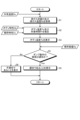
- FIG. 8 is a flow chart showing a state estimation method according to an embodiment.
- the exhaust gas flow rate sensor 16 detects the flow rate of the exhaust gas flowing into the flow path 23 .
- the exhaust gas temperature sensor 17 detects the temperature of the exhaust gas flowing into the flow path 23 .
- the exhaust gas flow rate acquisition unit 63 acquires the exhaust gas flow rate Df from the exhaust gas flow rate sensor 16 .
- the exhaust gas temperature acquisition unit 64 acquires the exhaust gas temperature Dt from the exhaust gas temperature sensor 17 (step S1).
- the outside air temperature sensor 18 detects the temperature of the outside air around the dump body 10 when the engine 6 is started.
- the outside air temperature acquisition unit 65 acquires the outside air temperature Do at the time when the engine 6 is started from the outside air temperature sensor 18 .
- the outside air temperature Do when the engine 6 is started is substantially equal to the temperature before the dump body 10 is heated by the exhaust gas.
- the outside air temperature Do can be regarded as an initial value relating to the body temperature Te before the dump body 10 is heated by the exhaust gas.
- the body temperature estimating section 67 estimates the body temperature Te of the predetermined portion MP of the inner surface of the dump body 10 based on the exhaust gas flow rate Df and the exhaust gas temperature Dt acquired in step S1. Further, the body temperature estimator 67 estimates the required time Pr until the body temperature Te reaches the specified temperature Tp based on the exhaust gas flow rate Df and the exhaust gas temperature Dt acquired in step S1 (step S2).
- the body temperature estimating section 67 may estimate the required time Pr based on the exhaust gas flow rate Df, the exhaust gas temperature Dt, and the outside air temperature Do.
- the body temperature estimator 67 may estimate the required time Pr based on the exhaust gas flow rate Df, the exhaust gas temperature Dt, the outside air temperature Do, and the body characteristic Cb.
- the body temperature estimator 67 may estimate the required time Pr based on the exhaust gas flow rate Df, the exhaust gas temperature Dt, the outside air temperature Do, and the cargo characteristics Cs.
- the body temperature display unit 73 causes the display 71 to display the body temperature Te estimated in step S2.
- the body temperature display unit 73 may display the required time Pr estimated in step S2 on the display 71 (step S3).
- the dump body 10 is loaded with the cargo by carrying out the loading operation in the loading field 51 .
- the dump truck 1 travels along the transport path 53 from the loading area 51 toward the dumping area 52 with the dump body 10 loaded with the cargo.
- the dumping propriety determination unit 69 determines whether the dumping operation of the dump body 10 is appropriate based on the body temperature Te estimated in step S2 (step S4). ).
- the dumping suitability determination unit 69 determines that the cargo has not yet been dried and determines that the dumping operation is inappropriate.
- the dumping suitability determination unit 69 determines that the cargo has been dried and that the dumping operation is appropriate.
- the dump propriety determining section 69 may determine propriety of the dump operation based on the elapsed time Pt after the body temperature Te reaches the specified temperature Tp.
- the dumping propriety determination unit 69 determines that the cargo has been dried when the elapsed time Pt from when the body temperature Te reaches the specified temperature Tp exceeds a predetermined specified time Pp. , it may be determined that it is appropriate to perform a dump operation.
- the dumping propriety determination unit 69 may determine the propriety of the dumping operation based on the body temperature Te and the cargo characteristic Cs.
- the dumping propriety determining unit 69 determines the body temperature Te and the cargo characteristic Cs.
- the propriety of the dump operation may be determined based on the volume Vc of the cargo and the contact area Ac of the cargo.
- step S4 if it is determined that the dumping operation is appropriate, that is, if it is determined that the adhesion of the cargo to the inner surface of the dump body 10 is suppressed when the dump body 10 performs the dumping operation (Ste S4: Yes), the dump suitability display unit 74 causes the display 71 to display that the dump operation is suitable (step S5).
- the driver of the dump truck 1 confirms the display 71 and recognizes that the dump operation is appropriate. can be implemented.
- step S4 if it is determined that the dumping operation is inappropriate, that is, it is determined that there is a high possibility that at least part of the cargo will adhere to the inner surface of the dump body 10 when the dump body 10 performs the dumping operation. If so (step S4: No), the dump suitability display unit 74 causes the display 71 to display that the dump operation is inappropriate (step S6).
- the driver of the dump truck 1 confirms the display 71 and recognizes that the dump operation is inappropriate, and waits until it is determined that the dump operation is appropriate. can be done.
- FIG. 9 is a block diagram illustrating a computer system 1000 according to an embodiment.
- a computer system 1000 includes a processor 1001 such as a CPU (Central Processing Unit), a main memory 1002 including non-volatile memory such as ROM (Read Only Memory) and volatile memory such as RAM (Random Access Memory), It has a storage 1003 and an interface 1004 including an input/output circuit.
- the respective functions of the controller 60 and the display controller 72 described above are stored in the storage 1003 as computer programs.
- the processor 1001 reads a computer program from the storage 1003, develops it in the main memory 1002, and executes the above-described processing according to the computer program. Note that the computer program may be distributed to the computer system 1000 via a network.
- the computer program or computer system 1000 detects the flow rate of the exhaust gas flowing into the channel 23 of the dump body 10, detects the temperature of the exhaust gas flowing into the channel 23, and detects the temperature of the exhaust gas according to the above-described embodiments. Acquiring an exhaust gas flow rate Df indicating the detection data of the flow rate, obtaining an exhaust gas temperature Dt indicating the detection data of the temperature of the exhaust gas, and based on the exhaust gas flow rate Df and the exhaust gas temperature Dt, the dump body contacting the cargo. and estimating a body temperature Te that indicates the temperature of the predetermined portion MP on the inner surface of the body 10 .
- the computer program or computer system 1000 can also determine whether the dumping operation of the dumping body 10 is appropriate based on the body temperature Te according to the embodiment described above.
- the state estimation system 100 includes the exhaust gas flow rate acquisition unit 63 for acquiring the exhaust gas flow rate Df indicating the detection data of the flow rate of the exhaust gas flowing into the flow path 23 of the dump body 10, and the flow path 23 an exhaust gas temperature acquisition unit 64 that acquires the exhaust gas temperature Dt indicating the detected data of the temperature of the exhaust gas flowing into the dump body 10, and based on the exhaust gas flow rate Df and the exhaust gas temperature Dt, a predetermined portion MP of the inner surface of the dump body 10 that contacts the cargo. and a body temperature estimator 67 that estimates a body temperature Te that indicates the temperature.
- the body temperature Te of the inner surface of the dump body 10 can be acquired without installing a temperature sensor for detecting the temperature of the inner surface of the dump body 10 in the dump body 10, for example. Further, according to the embodiment, the temperature (temperature distribution) of the entire inner surface of the dump body 10 is not estimated, but the body temperature Te of the predetermined portion MP is estimated. be done.
- a plurality of predetermined parts MP are defined on the inner surface of the dump body 10 .
- Body temperature estimation unit 67 estimates body temperature Te of each of a plurality of predetermined parts MP. Thereby, a rough temperature distribution of the inner surface of the dump body 10 is estimated.
- the body temperature estimation unit 67 estimates the required time Pr until the body temperature Te reaches the specified temperature Tp based on the exhaust gas flow rate Df and the exhaust gas temperature Dt. This allows the driver to recognize the required time Pr. Also, the driver can be aware of the approximate time until drying of the cargo is achieved.
- the state estimation system 100 includes an outside air temperature acquisition unit 65 that acquires the outside air temperature Do indicating the detection data of the outside air temperature around the dump body 10 .
- the body temperature estimating section 67 can highly accurately estimate the required time Pr based on the exhaust gas flow rate Df, the exhaust gas temperature Dt, and the outside air temperature Do.
- the state estimation system 100 further includes a body characteristic storage section 61 that stores body characteristics Cb that indicate the characteristics of the dump body 10 .
- the body temperature estimator 67 can highly accurately estimate the required time Pr based on the exhaust gas flow rate Df, the exhaust gas temperature Dt, the outside air temperature Do, and the body characteristic Cb.
- the state estimation system 100 includes a body temperature display section 73 that displays the body temperature Te on a display 71 arranged inside the cab 9 of the dump truck 1 . Thereby, the driver can confirm the body temperature Te displayed on the display 71 and can recognize the degree of heating of the inner surface of the dump body 10 .
- the state estimation system 100 includes a dumping suitability determination unit 69 that determines whether the dumping operation of the dumping body 10 is appropriate based on the body temperature Te. As a result, the driver can perform the dumping operation at an appropriate timing based on the determination result of the dumping appropriateness determination unit 69 .
- the dumping propriety determination unit 69 determines whether the dumping operation is appropriate based on the elapsed time Pt after the body temperature Te reaches the specified temperature Tp. By the time the body temperature Te reaches the specified temperature Tp, there is a possibility that the cargo has not yet been dried.
- the dumping suitability determination unit 69 can appropriately determine whether the dumping operation of the dump body 10 is appropriate based on the elapsed time Pt.
- the state estimation system 100 includes a cargo characteristics storage unit 62 that stores cargo characteristics Cs that indicate cargo characteristics.
- the dumping suitability determination unit 69 can appropriately determine whether the dumping operation is appropriate based on the body temperature Te and the cargo characteristic Cs.
- the state estimation system 100 includes a cargo volume acquisition unit 66 that acquires a cargo volume Da that indicates detection data of the weight of the cargo loaded on the dump body 10, and based on the cargo volume Da, the volume Vc of the cargo and the dump body of the cargo.
- a loading state estimating unit 68 for estimating a contact area Ac with the inner surface of 10 is further provided. Accordingly, the dumping propriety determination section 69 can more appropriately determine the propriety of the dumping operation based on the body temperature Te, the cargo characteristics Cs, the volume Vc of the cargo, and the contact area Ac of the cargo.
- the state estimation system 100 includes a dumping suitability display section 74 that displays the judgment result of the dumping suitability judgment section 69 on the display 71 arranged inside the cab 9 of the dump truck 1 .
- the driver can confirm whether or not the dumping operation displayed on the display 71 is appropriate, and can perform the dumping operation of the dump body 10 at an appropriate timing.
- the output device 35 includes a display device.
- Output device 35 may include an audio output device.
- the audio output device outputs audio data as output data.
- the body temperature Te and the result of determining whether the damping operation is appropriate may be output as audio data.
- the controller 60 includes the body characteristic storage unit 61, the cargo characteristic storage unit 62, the exhaust gas flow rate acquisition unit 63, the exhaust gas temperature acquisition unit 64, the outside air temperature acquisition unit 65, the cargo weight acquisition unit 66, the body temperature estimation
- a display controller 72 has functions of a body temperature display unit 73 and a dumping suitability display unit 74 . At least part of the functions of the controller 60 may be provided in the display controller 72 , and at least part of the functions of the display controller 72 may be provided in the controller 60 . Also, the controller 60 and the display controller 72 may be integrated.
- a body characteristic storage unit 61 a cargo characteristic storage unit 62, an exhaust gas flow rate acquiring unit 63, an exhaust gas temperature acquiring unit 64, an outside air temperature acquiring unit 65, a cargo weight acquiring unit 66, a body temperature estimating unit 67, a cargo condition estimating unit 68,
- Each of the dumping suitability determination unit 69, the body temperature display unit 73, and the dumping suitability display unit 74 may be configured by separate hardware (computer system).
- an external computer arranged outside the dump truck 1 may have at least part of the functions of the controller 60 .
- a cloud server is exemplified as an external computer.
- data detected by the exhaust gas flow rate sensor 16 and data detected by the exhaust gas temperature sensor 17 are transmitted to an external computer via a wireless communication network, and the external computer calculates the body temperature Te and determines whether the dumping operation is appropriate or not. good too.
- the body temperature Te calculated by the external computer and the determination result of the propriety of the dump operation may be transmitted to the dump truck 1 via the wireless communication network and output from the output device 35 .
- the dump truck 1 is a manned dump truck operated by a driver.
- the dump truck 1 may be an unmanned dump truck that operates based on control commands sent from a management computer of a control facility.
- the dump truck 1 may be a cabless dump truck that does not have the cab 9 .
- the output device 35 may be omitted. In that case, the output device 35 may be provided in the control facility.
- the dump propriety judging section 69 may determine that the dump truck cannot perform the dump operation.
- the dump truck 1 is of rigid frame type.
- the dump truck 1 may be articulated.
- the dump truck 1 is of the rear dump type.
- the dump truck 1 may be of a side dump type in which the cargo is discharged from the dump body 10 by tilting the dump body 10 leftward or rightward.
Landscapes
- Physics & Mathematics (AREA)
- General Physics & Mathematics (AREA)
- Engineering & Computer Science (AREA)
- Transportation (AREA)
- Mechanical Engineering (AREA)
- Combined Controls Of Internal Combustion Engines (AREA)
- Exhaust Gas After Treatment (AREA)
- Measuring Temperature Or Quantity Of Heat (AREA)
Abstract
Description
図1は、実施形態に係るダンプトラック1を示す側面図である。実施形態において、ダンプトラック1は、運転者の運転操作により稼働する有人ダンプトラックである。ダンプトラック1は、リジッドフレーム式のダンプトラックである。
図2は、実施形態に係るダンプボディ10を示す斜視図である。図2に示すように、ダンプボディ10は、前板11と、前板11の下端部に接続される底板12と、前板11の左右の端部及び底板12の左右の端部に接続される側板13と、前板11の上端部に接続されるプロテクタ板14とを有する。
図3は、実施形態に係るダンプトラック1を模式的に示す図である。図3に示すように、ダンプトラック1は、エンジン6と、導管24と、後処理装置15と、導管25と、ダンプボディ10と、排ガス流量センサ16と、排ガス温度センサ17と、外気温度センサ18と、積荷重量センサ19と、コントローラ60と、出力装置35とを備える。
図4は、実施形態に係るキャブ9の内部を示す図である。図4に示すように、キャブ9の内部には、運転シート31、ハンドル32、アクセルペダル33、ブレーキペダル34、出力装置35、及び操作装置40が配置される。
図5は、実施形態に係るダンプトラック1が稼働する作業現場50を模式的に示す図である。ダンプトラック1は、作業現場50で稼働する自走式のオフロードダンプトラックである。実施形態において、作業現場50は、鉱山である。鉱山とは、鉱物を採掘する事業場をいう。
図6は、実施形態に係る状態推定システム100を示す機能ブロック図である。状態推定システム100は、ダンプトラック1に搭載される。状態推定システム100は、排ガス流量センサ16の検出データと排ガス温度センサ17の検出データとに基づいて、積荷と接触するダンプボディ10の内面の所定部位MPの温度を示すボディ温度Teを推定する。また、状態推定システム100は、推定したボディ温度Teに基づいて、ダンプボディ10のダンプ動作の適否を判定する。
図8は、実施形態に係る状態推定方法を示すフローチャートである。エンジン6が起動されると、エンジン6から排ガスが排出される。エンジン6から排出された排ガスは、流路23に供給される。流路23に流入する排ガスの流量が排ガス流量センサ16により検出される。流路23に流入する排ガスの温度が排ガス温度センサ17により検出される。排ガス流量取得部63は、排ガス流量センサ16から排ガス流量Dfを取得する。排ガス温度取得部64は、排ガス温度センサ17から排ガス温度Dtを取得する(ステップS1)。
図9は、実施形態に係るコンピュータシステム1000を示すブロック図である。上述のコントローラ60及び表示コントローラ72のそれぞれは、コンピュータシステム1000を含む。コンピュータシステム1000は、CPU(Central Processing Unit)のようなプロセッサ1001と、ROM(Read Only Memory)のような不揮発性メモリ及びRAM(Random Access Memory)のような揮発性メモリを含むメインメモリ1002と、ストレージ1003と、入出力回路を含むインターフェース1004とを有する。上述のコントローラ60及び表示コントローラ72のそれぞれの機能は、コンピュータプログラムとしてストレージ1003に記憶されている。プロセッサ1001は、コンピュータプログラムをストレージ1003から読み出してメインメモリ1002に展開し、コンピュータプログラムに従って上述の処理を実行する。なお、コンピュータプログラムは、ネットワークを介してコンピュータシステム1000に配信されてもよい。
以上説明したように、実施形態において、状態推定システム100は、ダンプボディ10の流路23に流入する排ガスの流量の検出データを示す排ガス流量Dfを取得する排ガス流量取得部63と、流路23に流入する排ガスの温度の検出データを示す排ガス温度Dtを取得する排ガス温度取得部64と、排ガス流量Dfと排ガス温度Dtとに基づいて、積荷と接触するダンプボディ10の内面の所定部位MPの温度を示すボディ温度Teを推定するボディ温度推定部67と、を備える。
上述の実施形態においては、出力装置35が表示装置を含むこととした。出力装置35は、音声出力装置を含んでもよい。音声出力装置は、出力データとして音声データを出力する。例えばボディ温度Te及びダンプ動作の適否の判定結果が音声データとして出力されてもよい。
Claims (15)
- エンジンと前記エンジンから排出された排ガスが流通する流路を有し積荷が積載されるダンプボディとを備えるダンプトラックの状態推定システムであって、
前記流路に流入する前記排ガスの流量の検出データを示す排ガス流量を取得する排ガス流量取得部と、
前記流路に流入する前記排ガスの温度の検出データを示す排ガス温度を取得する排ガス温度取得部と、
前記排ガス流量と前記排ガス温度とに基づいて、前記積荷と接触する前記ダンプボディの内面の所定部位の温度を示すボディ温度を推定するボディ温度推定部と、を備える、
状態推定システム。 - 前記所定部位は、前記内面に複数規定され、
前記ボディ温度推定部は、複数の前記所定部位のそれぞれのボディ温度を推定する、
請求項1に記載の状態推定システム。 - 前記ボディ温度推定部は、前記排ガス流量と前記排ガス温度とに基づいて、前記ボディ温度が規定温度に到達するまでの所要時間を推定する、
請求項1又は請求項2に記載の状態推定システム。 - 前記ダンプボディの周囲の外気の温度の検出データを示す外気温度を取得する外気温度取得部を備え、
前記ボディ温度推定部は、前記排ガス流量と前記排ガス温度と前記外気温度とに基づいて、前記所要時間を推定する、
請求項3に記載の状態推定システム。 - 前記ダンプボディの特性を示すボディ特性を記憶するボディ特性記憶部を備え、
前記ボディ温度推定部は、前記排ガス流量と前記排ガス温度と前記外気温度と前記ボディ特性とに基づいて、前記所要時間を推定する、
請求項4に記載の状態推定システム。 - 前記積荷の特性を示す積荷特性を記憶する積荷特性記憶部を備え、
前記ボディ温度推定部は、前記排ガス流量と前記排ガス温度と前記外気温度と前記積荷特性とに基づいて、前記所要時間を推定する、
請求項4に記載の状態推定システム。 - 前記ダンプトラックのキャブの内部に配置されたディスプレイに前記ボディ温度を表示させるボディ温度表示部を備える、
請求項1から請求項6のいずれか一項に記載の状態推定システム。 - 前記ボディ温度に基づいて、前記ダンプボディのダンプ動作の適否を判定するダンプ適否判定部を備える、
請求項1又は請求項2に記載の状態推定システム。 - 前記ダンプ適否判定部は、前記ボディ温度が規定温度に到達してからの経過時間に基づいて、前記ダンプ動作の適否を判定する、
請求項8に記載の状態推定システム。 - 前記積荷の特性を示す積荷特性を記憶する積荷特性記憶部を備え、
前記ダンプ適否判定部は、前記ボディ温度と前記積荷特性とに基づいて、前記ダンプ動作の適否を判定する、
請求項8又は請求項9に記載の状態推定システム。 - 前記ダンプボディに積載された前記積荷の重量の検出データを示す積荷重量を取得する積荷重量取得部と、
前記積荷重量に基づいて、前記積荷の体積及び前記積荷の前記ダンプボディの内面との接触面積を推定する積荷状態推定部と、を備え、
前記ダンプ適否判定部は、前記ボディ温度と前記積荷特性と前記積荷の体積と前記積荷の接触面積とに基づいて、前記ダンプ動作の適否を判定する、
請求項10に記載の状態推定システム。 - 前記ダンプトラックのキャブの内部に配置されたディスプレイに前記ダンプ適否判定部の判定結果を表示させるダンプ適否表示部を備える、
請求項8から請求項11のいずれか一項に記載の状態推定システム。 - エンジンと、
前記エンジンからの排ガスが流通する流路を有するダンプボディと、
請求項1から請求項12のいずれか一項に記載の状態推定システムと、を備える、
ダンプトラック。 - エンジンと前記エンジンから排出された排ガスが流通する流路を有し積荷が積載されるダンプボディとを備えるダンプトラックの状態推定方法であって、
前記流路に流入する前記排ガスの流量を検出することと、
前記流路に流入する前記排ガスの温度を検出することと、
前記排ガスの流量の検出データを示す排ガス流量を取得することと、
前記排ガスの温度の検出データを示す排ガス温度を取得することと、
前記排ガス流量と前記排ガス温度とに基づいて、前記積荷と接触する前記ダンプボディの内面における所定部位の温度を示すボディ温度を推定することと、を含む、
状態推定方法。 - 前記ボディ温度に基づいて、前記ダンプボディのダンプ動作の適否を判定することを含む、
請求項14に記載の状態推定方法。
Priority Applications (3)
| Application Number | Priority Date | Filing Date | Title |
|---|---|---|---|
| CA3228557A CA3228557A1 (en) | 2021-09-16 | 2022-08-09 | State estimation system, dump truck, and state estimation method |
| CN202280055909.XA CN117794781B (zh) | 2021-09-16 | 2022-08-09 | 状态推断系统、自卸车以及状态推断方法 |
| US18/683,518 US12657970B2 (en) | 2021-09-16 | 2022-08-09 | State estimation system, dump truck, and state estimation method |
Applications Claiming Priority (2)
| Application Number | Priority Date | Filing Date | Title |
|---|---|---|---|
| JP2021-151402 | 2021-09-16 | ||
| JP2021151402A JP7742263B2 (ja) | 2021-09-16 | 2021-09-16 | 状態推定システム、ダンプトラック、及び状態推定方法 |
Publications (1)
| Publication Number | Publication Date |
|---|---|
| WO2023042575A1 true WO2023042575A1 (ja) | 2023-03-23 |
Family
ID=85602746
Family Applications (1)
| Application Number | Title | Priority Date | Filing Date |
|---|---|---|---|
| PCT/JP2022/030363 Ceased WO2023042575A1 (ja) | 2021-09-16 | 2022-08-09 | 状態推定システム、ダンプトラック、及び状態推定方法 |
Country Status (5)
| Country | Link |
|---|---|
| US (1) | US12657970B2 (ja) |
| JP (1) | JP7742263B2 (ja) |
| CN (1) | CN117794781B (ja) |
| CA (1) | CA3228557A1 (ja) |
| WO (1) | WO2023042575A1 (ja) |
Families Citing this family (1)
| Publication number | Priority date | Publication date | Assignee | Title |
|---|---|---|---|---|
| US12583375B2 (en) * | 2023-05-26 | 2026-03-24 | Caterpillar Global Mining Equipment Llc | Dump body and front wall retrofittable heat transfer system |
Citations (4)
| Publication number | Priority date | Publication date | Assignee | Title |
|---|---|---|---|---|
| JPH11151480A (ja) * | 1997-11-18 | 1999-06-08 | Sankyo Techno Kk | 生ゴミ処理装置及び生ゴミ処理方法 |
| US7743604B1 (en) * | 2007-03-23 | 2010-06-29 | Daniel Albanesi | Apparatus for heating the dump body of a dump truck having a diesel particulate filter |
| US20100170228A1 (en) * | 2007-12-18 | 2010-07-08 | Volvo Group North America, Inc. | Method and apparatus for truck heated dump body |
| JP2013147881A (ja) * | 2012-01-20 | 2013-08-01 | Hitachi Constr Mach Co Ltd | 寒冷地仕様の作業機械 |
Family Cites Families (10)
| Publication number | Priority date | Publication date | Assignee | Title |
|---|---|---|---|---|
| US6622548B1 (en) * | 2002-06-11 | 2003-09-23 | General Motors Corporation | Methods and apparatus for estimating gas temperatures within a vehicle engine |
| US7320504B2 (en) * | 2005-08-18 | 2008-01-22 | Mobile Heat Exchange, Llc | Vehicle heater using engine exhaust |
| CN101054108A (zh) * | 2007-04-06 | 2007-10-17 | 大连海事大学 | 油轮货油加热自动测控系统 |
| US20120169109A1 (en) * | 2010-12-30 | 2012-07-05 | Trinity Industries, Inc. | Heated Dump Body |
| JP2012201227A (ja) * | 2011-03-25 | 2012-10-22 | Hitachi Constr Mach Co Ltd | ダンプトラックの荷台加熱機構 |
| JP2015112907A (ja) * | 2013-12-09 | 2015-06-22 | 日立建機株式会社 | ダンプトラックおよびその荷台 |
| US20180194260A1 (en) * | 2017-01-10 | 2018-07-12 | Crysteel Manufacturing Inc. | System for dump body heating and temperature control |
| JP6501854B1 (ja) * | 2017-11-22 | 2019-04-17 | 三和ボデー工業株式会社 | ダンプカーの排気リフト装置 |
| JP7603439B2 (ja) * | 2019-12-25 | 2024-12-20 | 新明和工業株式会社 | 特装車の積載重量推定システム |
| CN211765141U (zh) * | 2019-12-25 | 2020-10-27 | 内蒙古北方重型汽车股份有限公司 | 设置有加热通道结构的矿用自卸车车厢 |
-
2021
- 2021-09-16 JP JP2021151402A patent/JP7742263B2/ja active Active
-
2022
- 2022-08-09 US US18/683,518 patent/US12657970B2/en active Active
- 2022-08-09 CA CA3228557A patent/CA3228557A1/en active Pending
- 2022-08-09 WO PCT/JP2022/030363 patent/WO2023042575A1/ja not_active Ceased
- 2022-08-09 CN CN202280055909.XA patent/CN117794781B/zh active Active
Patent Citations (4)
| Publication number | Priority date | Publication date | Assignee | Title |
|---|---|---|---|---|
| JPH11151480A (ja) * | 1997-11-18 | 1999-06-08 | Sankyo Techno Kk | 生ゴミ処理装置及び生ゴミ処理方法 |
| US7743604B1 (en) * | 2007-03-23 | 2010-06-29 | Daniel Albanesi | Apparatus for heating the dump body of a dump truck having a diesel particulate filter |
| US20100170228A1 (en) * | 2007-12-18 | 2010-07-08 | Volvo Group North America, Inc. | Method and apparatus for truck heated dump body |
| JP2013147881A (ja) * | 2012-01-20 | 2013-08-01 | Hitachi Constr Mach Co Ltd | 寒冷地仕様の作業機械 |
Also Published As
| Publication number | Publication date |
|---|---|
| JP7742263B2 (ja) | 2025-09-19 |
| CN117794781B (zh) | 2026-03-31 |
| US12657970B2 (en) | 2026-06-16 |
| US20240355155A1 (en) | 2024-10-24 |
| CN117794781A (zh) | 2024-03-29 |
| CA3228557A1 (en) | 2023-03-23 |
| JP2023043662A (ja) | 2023-03-29 |
Similar Documents
| Publication | Publication Date | Title |
|---|---|---|
| CN107176166A (zh) | 非公路矿用自卸车装载监控记录系统及装载监控记录方法 | |
| BRPI0711154A2 (pt) | sistema de controle de estabilidade com sensibilidades múltiplas | |
| JP6736597B2 (ja) | ホイールローダ | |
| CN104040133A (zh) | 作业车辆 | |
| CN105332805B (zh) | 车辆发动机的节能控制系统、方法、装置及工程车辆 | |
| JP6084306B2 (ja) | 作業車両及び作業車両の制御方法 | |
| JP2004513288A (ja) | 排気ガス処理システムの制御方法および制御装置 | |
| JP7742263B2 (ja) | 状態推定システム、ダンプトラック、及び状態推定方法 | |
| EP3561251B1 (en) | System for regenerating dpf during operation of engine-powered forklift and method therefor | |
| US10240506B2 (en) | Estimating nitrogen oxide values for vehicles | |
| US8700274B1 (en) | Method of determining when a bed of a hauling machine is empty | |
| JP6560004B2 (ja) | 選択触媒還元熱管理方法及びシステム | |
| CN112758062A (zh) | 车辆的组合式冷却和水制动系统及冷却车辆的推进装置和水制动车辆的一对车轮的方法 | |
| CN113748423A (zh) | 机器的动态侧翻控制系统 | |
| JP4550698B2 (ja) | ダンプトラックの油圧駆動装置 | |
| JP2015021810A (ja) | 推定車重の算出方法と車両 | |
| JP6794806B2 (ja) | 車両重量推定装置及び車両重量推定方法 | |
| CN113829826A (zh) | 结合空气悬挂的紧急制动控制方法、装置及电子设备 | |
| JP2009023595A (ja) | 運搬車両のサスペンション装置 | |
| JP7105652B2 (ja) | 電気駆動ダンプトラック | |
| US11428180B2 (en) | Method for controlling a vehicle propulsion system | |
| JP2023176621A (ja) | ダンプトラック | |
| JP6949798B2 (ja) | 運転支援装置 | |
| US20160297441A1 (en) | System and method for machine cost optimization | |
| KR102448750B1 (ko) | 휠 로더의 제어 방법 |
Legal Events
| Date | Code | Title | Description |
|---|---|---|---|
| 121 | Ep: the epo has been informed by wipo that ep was designated in this application |
Ref document number: 22869722 Country of ref document: EP Kind code of ref document: A1 |
|
| WWE | Wipo information: entry into national phase |
Ref document number: 3228557 Country of ref document: CA |
|
| WWE | Wipo information: entry into national phase |
Ref document number: 202280055909.X Country of ref document: CN |
|
| WWE | Wipo information: entry into national phase |
Ref document number: 18683518 Country of ref document: US |
|
| NENP | Non-entry into the national phase |
Ref country code: DE |
|
| 122 | Ep: pct application non-entry in european phase |
Ref document number: 22869722 Country of ref document: EP Kind code of ref document: A1 |
|
| WWG | Wipo information: grant in national office |
Ref document number: 18683518 Country of ref document: US |