WO2023042541A1 - 蓄電モジュール用圧力調整弁 - Google Patents
蓄電モジュール用圧力調整弁 Download PDFInfo
- Publication number
- WO2023042541A1 WO2023042541A1 PCT/JP2022/028040 JP2022028040W WO2023042541A1 WO 2023042541 A1 WO2023042541 A1 WO 2023042541A1 JP 2022028040 W JP2022028040 W JP 2022028040W WO 2023042541 A1 WO2023042541 A1 WO 2023042541A1
- Authority
- WO
- WIPO (PCT)
- Prior art keywords
- discharge
- pressure regulating
- valve body
- valve
- pressure
- Prior art date
Links
- 230000001105 regulatory effect Effects 0.000 claims description 67
- 239000008151 electrolyte solution Substances 0.000 claims description 6
- 238000005192 partition Methods 0.000 claims description 4
- 230000004308 accommodation Effects 0.000 claims 1
- 239000003792 electrolyte Substances 0.000 abstract description 19
- 230000002093 peripheral effect Effects 0.000 description 19
- 239000007789 gas Substances 0.000 description 8
- 239000000463 material Substances 0.000 description 7
- 230000005611 electricity Effects 0.000 description 3
- UFHFLCQGNIYNRP-UHFFFAOYSA-N Hydrogen Chemical compound [H][H] UFHFLCQGNIYNRP-UHFFFAOYSA-N 0.000 description 1
- 230000000694 effects Effects 0.000 description 1
- 229910052987 metal hydride Inorganic materials 0.000 description 1
- 230000000630 rising effect Effects 0.000 description 1
- 229920003002 synthetic resin Polymers 0.000 description 1
- 239000000057 synthetic resin Substances 0.000 description 1
Images


Classifications
-
- F—MECHANICAL ENGINEERING; LIGHTING; HEATING; WEAPONS; BLASTING
- F16—ENGINEERING ELEMENTS AND UNITS; GENERAL MEASURES FOR PRODUCING AND MAINTAINING EFFECTIVE FUNCTIONING OF MACHINES OR INSTALLATIONS; THERMAL INSULATION IN GENERAL
- F16K—VALVES; TAPS; COCKS; ACTUATING-FLOATS; DEVICES FOR VENTING OR AERATING
- F16K17/00—Safety valves; Equalising valves, e.g. pressure relief valves
- F16K17/02—Safety valves; Equalising valves, e.g. pressure relief valves opening on surplus pressure on one side; closing on insufficient pressure on one side
-
- F—MECHANICAL ENGINEERING; LIGHTING; HEATING; WEAPONS; BLASTING
- F16—ENGINEERING ELEMENTS AND UNITS; GENERAL MEASURES FOR PRODUCING AND MAINTAINING EFFECTIVE FUNCTIONING OF MACHINES OR INSTALLATIONS; THERMAL INSULATION IN GENERAL
- F16K—VALVES; TAPS; COCKS; ACTUATING-FLOATS; DEVICES FOR VENTING OR AERATING
- F16K27/00—Construction of housing; Use of materials therefor
- F16K27/02—Construction of housing; Use of materials therefor of lift valves
- F16K27/0209—Check valves or pivoted valves
-
- H—ELECTRICITY
- H01—ELECTRIC ELEMENTS
- H01M—PROCESSES OR MEANS, e.g. BATTERIES, FOR THE DIRECT CONVERSION OF CHEMICAL ENERGY INTO ELECTRICAL ENERGY
- H01M50/00—Constructional details or processes of manufacture of the non-active parts of electrochemical cells other than fuel cells, e.g. hybrid cells
- H01M50/30—Arrangements for facilitating escape of gases
- H01M50/317—Re-sealable arrangements
- H01M50/325—Re-sealable arrangements comprising deformable valve members, e.g. elastic or flexible valve members
-
- F—MECHANICAL ENGINEERING; LIGHTING; HEATING; WEAPONS; BLASTING
- F16—ENGINEERING ELEMENTS AND UNITS; GENERAL MEASURES FOR PRODUCING AND MAINTAINING EFFECTIVE FUNCTIONING OF MACHINES OR INSTALLATIONS; THERMAL INSULATION IN GENERAL
- F16K—VALVES; TAPS; COCKS; ACTUATING-FLOATS; DEVICES FOR VENTING OR AERATING
- F16K15/00—Check valves
- F16K15/14—Check valves with flexible valve members
-
- Y—GENERAL TAGGING OF NEW TECHNOLOGICAL DEVELOPMENTS; GENERAL TAGGING OF CROSS-SECTIONAL TECHNOLOGIES SPANNING OVER SEVERAL SECTIONS OF THE IPC; TECHNICAL SUBJECTS COVERED BY FORMER USPC CROSS-REFERENCE ART COLLECTIONS [XRACs] AND DIGESTS
- Y02—TECHNOLOGIES OR APPLICATIONS FOR MITIGATION OR ADAPTATION AGAINST CLIMATE CHANGE
- Y02E—REDUCTION OF GREENHOUSE GAS [GHG] EMISSIONS, RELATED TO ENERGY GENERATION, TRANSMISSION OR DISTRIBUTION
- Y02E60/00—Enabling technologies; Technologies with a potential or indirect contribution to GHG emissions mitigation
- Y02E60/10—Energy storage using batteries
Definitions
- the present disclosure relates to a pressure regulating valve for power storage modules.
- Electricity storage modules such as conventional nickel-metal hydride batteries have a pressure control valve that opens to discharge gas from the module when gas such as hydrogen gas is generated due to overdischarge, etc., and the pressure inside the module reaches a predetermined level.
- pressure regulating valves for power storage modules (hereinafter referred to as "pressure regulating valves")
- pressure regulating valves there are known pressure regulating valves that have a simple configuration and are capable of regulating pressure in a plurality of internal spaces between bipolar electrodes (for example, International Publication No. 2019/064843).
- the electrolyte When the pressure regulating valve opens, the electrolyte may be discharged along with the gas. In this case, the electrolyte may accumulate inside the pressure regulating valve.
- Conventional pressure regulating valves have multiple valve bodies in one discharge port, making it difficult to discharge the electrolyte without delay. As a result, the plurality of valve bodies are immersed in the electrolytic solution. In this case, in the conventional pressure regulating valve, when a plurality of valve bodies are opened at the same time and the electrolyte is discharged, a short circuit may occur between the cells through the electrolyte.
- An object of the present disclosure is to provide a pressure regulating valve that can improve electrolyte discharge.
- a pressure regulating valve attachable to a power storage module, A plurality of valve bodies that open according to the pressure in the power storage module to release the pressure in the power storage module, each valve body having a discharge for releasing pressure; The interior is isolated from other adjacent valve body parts, a plurality of valve bodies, A pressure regulating valve having
- FIG. 2 is a perspective view schematically showing an electricity storage module to which the pressure regulating valve of the first embodiment is connected;
- 1 is an exploded perspective view showing a schematic configuration of a pressure regulating valve according to a first embodiment;
- Front view of the case portion of the pressure regulating valve of FIG. Plan view of the case part of FIG. 9 is a front view of a cover portion as a lid portion of the pressure regulating valve of FIG. 8.
- FIG. 1 is a perspective view schematically showing an electricity storage module 500 to which the pressure regulating valve 1 of the first embodiment is connected.
- FIG. 2 is an exploded perspective view showing a schematic configuration of the pressure regulating valve 1 of the first embodiment.
- FIG. 3 is a cross-sectional view of the pressure regulating valve 1. As shown in FIG. 2 and subsequent drawings, the pressure regulating valve 1 is a partial enlarged view of the portion A shown in FIG.
- the axial direction of the cylindrical valve element 30 in the pressure regulating valve 1 shown in FIGS. 2 and 3 is defined as the Y-axis direction.
- the Y-axis direction is also referred to as the front-rear direction.
- the +Y axis direction is also called one end side (first direction side)
- the ⁇ Y axis direction is also called the other end side (second direction side).
- the direction of the pressure regulating valve 1 viewed in the +Y-axis direction is defined as the front direction.
- One of the directions (X-axis direction) orthogonal to the front-rear direction (Y-axis direction) is defined as the width direction.
- the width direction is the longitudinal direction of the pressure regulating valve 1 .
- the width direction is also referred to as the left-right direction.
- a direction (Z-axis direction) perpendicular to both the front-rear direction (Y-axis direction) and the left-right direction (X-axis direction) is also referred to as an up-down direction or a height direction.
- the pressure regulating valve 1 of this embodiment has a plurality of valve body portions 10. As shown in FIG. The plurality of valve bodies 10 open according to the pressure inside the power storage module 500 to release the pressure inside the power storage module 500 . Each valve body 10 has a vent 118 for releasing pressure. The interior of each valve body portion 10 is isolated from the interior of the adjacent valve body portion 10 .
- the power storage module 500 has a frame 502 that holds a plurality of electrode plates.
- the frame 502 has openings 503 that communicate with the spaces between the electrode plates.
- Pressure regulating valve 1 closes opening 503 .
- the valve body portion 10 has a case portion 110 .
- the case portion 110 has a tubular portion 114 .
- One end of the tubular portion 114 is connected to the opening 503 to define an internal space S2.
- a columnar valve body 30, which is an elastic member, is accommodated in the internal space S2 of the tubular portion 114. As shown in FIG.
- the case part 110 further has a bottom part 111 , an opening part 113 , a pressure introduction part 115 , a cover part 116 and a projection part 117 .
- the bottom portion 111 is provided on the first direction side.
- the opening 113 is provided on the second direction side.
- the pressure introducing portion 115 penetrates through the bottom portion 111 .
- the cover portion 116 is a lid portion that closes the opening portion 113 .
- the projecting portion 117 is provided on the cover portion 116 and contacts the end face 31 of the valve body 30 from the second direction side.
- the pressure regulating valve 1 will be specifically described below.
- the pressure regulating valve 1 has multiple valve bodies 10 .
- the valve body portion 10 accommodates the valve body 30 .
- Valve body portion 10 is attached to opening 503 of power storage module 500 .
- the valve body portion 10 has a cylindrical portion 114 , a cover portion 116 , a discharge portion 118 and a valve body 30 .
- the material of the case part 110 and the cover part 116 is not particularly limited, and is synthetic resin, for example.
- the shape of the case portion 110 is, for example, a substantially rectangular parallelepiped shape.
- the shape of the case portion 110 is not particularly limited as long as it can block the opening 503 .
- the size of the case portion 110 can also be appropriately set in relation to the size of the power storage module 500 or the size of the opening 503, and is not particularly limited.
- the materials of the case portion 110 and the cover portion 116 may be the same material or different materials.
- FIG. 4 is a front view of the case portion 110 of the pressure regulating valve 1.
- FIG. FIG. 5 is a cross-sectional view of the case portion 110 taken along line AA.
- the case part 110 is, for example, a rectangular parallelepiped box whose width dimension is longer than its height dimension and front-rear dimension.
- the case portion 110 has a bottom portion 111 , an outer peripheral wall portion 112 , an opening portion 113 , a tubular portion 114 and a pressure introducing portion 115 .
- the bottom portion 111 is provided on the first direction side of the case portion 110 .
- the pressure regulating valve 1 is attached to the opening 503 of the frame 502
- the bottom 111 is attached so as to face the opening 503, as shown in FIG. In this state, the bottom portion 111 is formed so as to close the opening 503 .
- the outer peripheral wall portion 112 is provided at the end of the outer periphery of the bottom portion 111 .
- the outer peripheral wall portion 112 is provided at an end portion 1111 of the bottom portion 111 in the vertical direction.
- the outer peripheral wall portion 112 is a wall-shaped member rising from the end portion 1111 toward the second direction ( ⁇ Y axis direction). As shown in FIG. 4, the bottom portion 111 and the outer peripheral wall portion 112 define an internal space S1 inside the case portion 110 that is isolated from the outside.
- the opening 113 is provided at the end 1122 of the outer peripheral wall 112 on the second direction side.
- the second direction side of the internal space S1 of the case portion 110 is opened to the outside by the opening portion 113 .
- the cylindrical portion 114 is provided in the internal space S1 of the case portion 110.
- the cylindrical portion 114 has a cylindrical shape or a substantially cylindrical shape whose axial direction is the front-rear direction (Y-axis direction) in the case portion 110 .
- One or more tubular portions 114 are provided in the internal space S1.
- the number of cylindrical portions 114 is not particularly limited.
- the end of the tubular portion 114 on the first direction side is integrated with the inner side surface 1112 that is the surface on the second direction side of the bottom portion 111 .
- An end portion of the cylindrical portion 114 on the second direction side is opened toward the opening portion 113 .
- the cylindrical portion 114 is combined with a cover portion 116, which will be described later, so that the valve body 30 can be accommodated in the cylindrical or substantially cylindrical inner space S2 as shown in FIG.
- the internal space S ⁇ b>2 of the tubular portion 114 functions as a housing chamber for housing the valve body 30 .
- the pressure regulating valve 1 can accommodate a plurality of valve bodies 30 corresponding to the number of cylindrical portions 114 provided in the internal space S1.
- the pressure introduction part 115 is provided in a cylindrical part bottom part 1113 which is a bottom part located inside the cylindrical part 114 .
- the pressure introducing portion 115 is a through hole extending in the Y-axis direction in the cylindrical portion bottom portion 1113 . That is, the pressure introduction part 115 penetrates the first direction side and the second direction side of the cylindrical part bottom part 1113 .
- the pressure introduction part 115 is not limited to one provided near the center of the circular or substantially circular shape of the cylindrical part bottom part 1113 as shown in FIG. 4 .
- the pressure introduction part 115 is, for example, a cylindrical space.
- the shape of the pressure introduction part 115 is not particularly limited, and may be, for example, an elliptical columnar or polygonal columnar space.
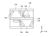
- FIG. 6 is a front view of the cover portion 116 of the pressure regulating valve 1.
- FIG. 7 is a plan view of the cover portion 116.
- the cover part 116 is, for example, a rectangular plate-like or substantially plate-like member whose width dimension is longer than its height dimension.
- the cover portion 116 has a cover portion body 1161 , projections 117 , discharge portions 118 and ribs 119 .
- the cover portion main body 1161 defines the general shape of the plate-like or substantially plate-like cover portion 116 described above. As long as the cover portion 116 can be combined with the case portion 110, the shape of the cover portion main body 1161 is not limited to the shapes shown in FIGS.
- the rib 119 is arranged on the second direction side of the cover body 1161 . That is, the rib 119 is provided on the opposite side of the case portion 110 in the cover portion main body 1161 .
- the rib 119 is an upright wall portion extending in the front-rear direction (Y-axis direction).
- the ribs 119 may be arranged corresponding to the positions of the cylindrical portion 114 and the discharge portion 118 .
- the ribs 119 surround the discharge portions 118 in the ⁇ Y-axis direction of the plurality of discharge portions 118 .
- the protrusion 117 is provided on the cover body 1161 .
- the projecting portion 117 has a projecting shape projecting in the Y-axis direction from the cover portion main body 1161 .
- a plurality of projecting portions 117 are provided corresponding to the number of discharge portions 118 .
- the protrusion 117 contacts the end face 31 of the valve body 30 .
- the projection portion 117 pressurizes the valve body 30 .
- the valve body 30 airtightly closes the pressure introducing portion 115 as described later.
- the shape and dimensions of the protrusion 117 are not particularly limited.
- the protrusion 117 may have, for example, a columnar shape, an elliptical columnar shape, or a polygonal columnar shape.
- the discharge portion 118 is formed in the cover portion main body 1161 .
- a discharge portion 118 is formed at a position overlapping the inner space S2 of the tubular portion 114 in a state where the opening portion 113 of the tubular portion 114 is closed by the cover portion 116 .
- the discharge portion 118 is an opening that communicates the inside and the outside of the cover body 1161 .
- the discharge portion 118 is a through hole extending in the front-rear direction (Y-axis direction) of the cover portion main body 1161 .
- the discharge portion 118 is provided corresponding to each of the cylindrical portions 114 forming the valve body portion 10 . Note that the specific shape of the discharge portion 118 is not limited to the examples in FIGS. 1, 5, and 6.
- FIG. A discharge portion 118 may be formed corresponding to each of the tubular portions 114 so as to communicate between the inside and the outside of the tubular portion 114 .
- the discharge part 118 is provided in each of the plurality of valve body parts 10 . At least one discharge portion 118 may be formed in one valve body portion 10 , and a plurality of discharge portions 118 may be formed in one valve body portion 10 .
- the outer surface of the cover main body 1161 and the ribs 119 are positioned between the plurality of discharge portions 118 . Therefore, the discharge portion 118 is isolated from the other discharge portions 118 by the cover portion main body 1161 and the ribs 119 , and is independent from the other discharge portions 118 without being in contact with the other discharge portions 118 .
- the cover portion main body 1161 and the ribs 119 function as partition portions that separate the plurality of discharge portions 118 from each other.
- the discharge portion 118 is arranged in the vertical direction (Z-axis direction), which is the direction in which the electrolyte accumulated in the inner space S2 of the cylindrical portion 114 flows when it leaks, and the discharge portion 118 corresponding to the other cylindrical portion 114 cannot be set.
- the discharge portion 118 is separated from the discharge portion 118 corresponding to the other cylindrical portion 114 at a predetermined interval in the width direction (X-axis direction) and does not overlap with the other discharge portion 118 .
- the ejection portions 118 are independent from each other without being in contact with other ejection portions 118 .
- the valve body 30 has a columnar shape and is housed in the tubular portion 114 .
- the material of the valve body 30 is, for example, an elastic member such as rubber.
- the material of the valve body 30 is not particularly limited as long as it is an elastic member.
- the valve body 30 covers the cylindrical portion bottom portion 1113 side of the cylindrical portion 114 .
- the length of the valve body 30 in the axial direction (Y-axis direction) is shorter than the outer diameter.
- the valve body 30 has a cylindrical shape, but as described above, the length in the axial direction (Y-axis direction) is shorter than the outer diameter (dimension in the Z-axis direction). Therefore, the valve body 30 can also be said to be plate-like or disk-like. More specifically, the valve body 30 can be substantially disc-shaped or the like.
- the valve body 30 closes the opening of the pressure introducing portion 115 by being inserted into the tubular portion 114 .
- pressure introducing portion 115 is maintained in an airtight state until the inside of power storage module 500 reaches a desired pressure.
- valve element 30 When the pressure inside power storage module 500 (hereinafter also simply referred to as “internal pressure”) rises to a desired value, valve element 30 is pushed out from cylindrical portion bottom 1113 according to the internal pressure of power storage module 500 . Open away.
- the value of the internal pressure of power storage module 500 at which valve body 30 separates from cylindrical portion bottom 1113 is determined so as to avoid excessive internal pressure of power storage module 500 due to valve body 30 opening.
- the value of the internal pressure of power storage module 500 at which valve element 30 separates from cylindrical portion bottom portion 1113 may vary depending on various conditions. Specifically, the value of the internal pressure may change according to individual differences (variations) of the valve body 30 and changes over time.
- a gap is generated between the valve body 30 and the bottom portion 1113 of the cylindrical portion by separating the valve body 30 from the bottom portion 1113 of the cylindrical portion.
- Compressed gas in power storage module 500 is introduced into pressure regulating valve 1 through this gap. Then, the pressure inside the power storage module 500 is lowered. Then, the valve body 30 returns to its original position inside the tubular portion 114 by elastic force, that is, the position in contact with the tubular portion bottom portion 1113 , and seals the pressure introducing portion 115 airtightly.
- the electrolytic solution is discharged together with the compressed gas. may be discharged. In this case, the electrolyte may accumulate inside the cylindrical portion 114 .
- Discharge portions 118 are provided in the cover portion main body 1161 corresponding to the plurality of cylindrical portions 114 that accommodate the valve bodies 30 . Discharge portion 118 discharges the electrolytic solution that has flowed into internal space S ⁇ b>2 of cylindrical portion 114 when valve body 30 is opened to the outside of cylindrical portion 114 . Therefore, the pressure regulating valve 1 can smoothly discharge the electrolyte accumulated inside the tubular portion 114 . The pressure regulating valve 1 prevents the valve body 30 from being immersed in the electrolytic solution.
- the discharge portion 118 provided corresponding to each of the plurality of valve bodies 30 is isolated from the other discharge portions 118 by the cover portion body 1161 . Therefore, when the plurality of valve bodies 30 are opened at the same time and the electrolyte is discharged, it is possible to prevent short circuits between the cells through the electrolyte.
- the pressure regulating valve 2 of the second embodiment opens according to the pressure inside the power storage module 500 shown in FIG. It has a plurality of valve bodies 20 for releasing the internal pressure.
- Each valve body portion 20 has a vent 218 for releasing pressure.
- the inside of each valve body portion 20 is isolated from other adjacent valve body portions 20 .
- the pressure regulating valve 2 closes an opening 503 communicating with the space between the electrode plates provided in the frame 502 in the frame 502 that holds the plurality of electrode plates of the power storage module 500 .
- the discharge portion 218 is provided on the side surface 220 of the tubular portion 214 and communicates the inside and the outside of the tubular portion 214 .
- a tubular portion 214 of the valve body portion 20 is provided in the case portion 210 . One end of the tubular portion 214 is connected to the opening.
- the tubular portion 214 has an internal space S2.
- the inner space S2 of the tubular portion 214 accommodates the columnar valve body 30, which is an elastic member.
- the case portion 210 has a bottom portion 211 , an opening portion 213 , a cylindrical portion 214 and a pressure introduction portion 215 in addition to the discharge portion 218 .
- the bottom portion 211 is provided on the first direction side.
- the opening 213 is provided on the second direction side.
- the tubular portion 214 is provided in the internal space S ⁇ b>1 of the valve body portion 20 and can accommodate the valve body 30 .
- the pressure introducing portion 215 penetrates through the bottom portion 211 .
- the pressure regulating valve 2 has a cover portion 216 and a protrusion portion 217 .
- the cover portion 216 is a lid portion that closes the opening portion 213 .
- the projecting portion 217 is provided on the cover portion 216 and contacts the end surface of the valve body 30 from the second direction side.
- the pressure regulating valve 2 will be specifically described below.
- the pressure regulating valve 2 has a plurality of valve bodies 20 . Similar to the pressure regulating valve 1 of the first embodiment, the valve body portion 20 accommodates the valve body 30 and is attached to the opening 503 of the power storage module 500 .
- valve body portion 20 has a cylindrical portion 214 , a discharge portion 218 , a cover portion 216 and a valve body 30 .
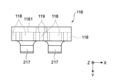
- FIG. 9 is a front view of the case portion 210 of the pressure regulating valve 2.
- FIG. 10 is a plan view of the case portion 210.
- the case part 210 is, for example, a rectangular parallelepiped box-shaped member whose width dimension is longer than its height dimension and front-rear dimension.
- the case portion 210 has a bottom portion 211 , an outer peripheral wall portion 212 , an opening portion 213 , a tubular portion 214 , a pressure introduction portion 215 and a discharge portion 218 .
- the case portion 210 differs from the case portion 110 of the first embodiment in that the side surface 220 of the tubular portion 214 and the outer peripheral wall portion 212 have a discharge portion 218 that communicates the inside and the outside of the tubular portion 214 .
- the discharge portion 218 is formed in the cylindrical or substantially cylindrical side surface 220 of the cylindrical portion 214 and the outer peripheral wall portion 212 .
- the discharge portion 218 is an opening that communicates between the inside and outside of the side surface 220 of the cylindrical portion 214 and between the inside and outside of the outer peripheral wall portion 212 .
- the discharge portion 218 extends in the front-rear direction (Y-axis direction) of the side surface 220 and the outer peripheral wall portion 212 .
- a discharge portion 218 is provided corresponding to each cylindrical portion 214 . Note that the specific shape of the discharge portion 218 is not limited to the examples in FIGS. 9 and 10 .
- a discharge portion 218 may be formed so as to communicate between the inside and outside of the side surface 220 .
- the discharge part 218 is provided corresponding to each of the plurality of tubular parts 214 . At least one discharge portion 218 may be formed in one tubular portion 214 . As shown in FIGS. 8 to 10, one tubular portion 214 may be formed with a plurality of discharge portions 218 . Between the plurality of discharge portions 218, the outer peripheral surface of the side surface 220 and the outer peripheral wall portion 212 are positioned. Therefore, the discharge portion 218 is isolated from the other discharge portions 218 by the side surface 220 and the outer peripheral wall portion 212 . The ejection portions 218 are independent from each other without contacting other ejection portions 218 .
- the side surface 220 of the cylindrical portion 214 and the outer peripheral wall portion 212 function as a partition wall portion that separates the plurality of discharge portions 218 from each other.
- the electrolyte accumulated in the internal space S2 of the cylindrical portion 214 flows out in the vertical direction (Z-axis direction) when leaking.
- the ejection portion 218 is not provided with an ejection portion 218 corresponding to another cylindrical portion 214 in the vertical direction (Z-axis direction).
- the discharge portion 118 is separated from the discharge portion 118 corresponding to the other cylindrical portion 114 with a predetermined gap in the width direction (X-axis direction) and does not overlap with the other discharge portion 218 .
- the discharge section 218 is isolated from the other discharge sections 218 and is independent from the other discharge sections 218 without being in contact with the other discharge sections 218 .
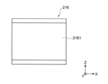
- FIG. 11 is a front view of the cover portion 216 of the pressure regulating valve 2.
- FIG. 12 is a plan view of the cover portion 216.
- the cover part 216 is, for example, a rectangular plate-like or substantially plate-like member whose width dimension is longer than its height dimension.
- the cover portion 216 has a cover portion main body 2161 and a projection portion 217 .
- the cover portion 216 of this embodiment differs from the cover portion 116 of the first embodiment in that it does not have the discharge portion 118 .
- the pressure regulating valve 2 when the valve element 30 is separated from the cylindrical portion bottom portion 2113 and the compressed gas in the power storage module 500 is discharged from the gap formed between the valve element 30 and the cylindrical portion bottom portion 2113. , the electrolyte may be expelled with the compressed gas.
- the internal space S ⁇ b>2 of the tubular portion 214 may be filled with electrolyte.
- the pressure regulating valve 2 is provided with discharge portions 218 on the side surface 220 and the outer peripheral wall portion 212 of the cylindrical portions 214 corresponding to the plurality of cylindrical portions 214 that accommodate the valve bodies 30 . Therefore, the pressure regulating valve 2 can smoothly discharge the electrolyte accumulated inside the tubular portion 214 . Therefore, the pressure regulating valve 2 can prevent the valve body 30 from being immersed in the electrolytic solution.
- the discharge portion 218 is isolated from other discharge portions 218 by the side surface 220 of the tubular portion 214 and the outer peripheral wall portion 212 . Therefore, when the plurality of valve bodies 30 are opened at the same time and the electrolyte is discharged, it is possible to prevent short circuits between the cells through the electrolyte.
- the present invention is not limited to the above-described embodiments of the present invention, and includes all aspects included in the concept of the present invention and the scope of claims. Moreover, each configuration may be selectively combined as appropriate so as to achieve at least part of the above-described problems and effects. For example, the shape, material, arrangement, size, etc. of each component in the above embodiments may be changed as appropriate according to the specific usage of the present invention.
- the cover portion main body 1161 of the cover portion 116 has the discharge portion 118 that communicates the inside and outside of the cover portion 116 .
- the side surface 220 of the tubular portion 214 and the outer peripheral wall portion 212 have a discharge portion 218 that communicates the inside and outside of the tubular portion 214 .
- both the cover portion and the case portion may have the discharge portion.
- Reference Signs List 1 2 Pressure regulating valves 10, 20 Valve body portion 31 End surface 30 Valve bodies 110, 210 Case portions 111, 211 Bottom portions 112, 212 Peripheral wall portions 113, 213 Opening portions 114, 214 Cylinder Shaped portions 115, 215 Pressure introduction portions 116, 216 Cover portions 117, 217 Protrusions 118, 218 Discharge portion 119 Rib 220 Side surface 500 Storage module 502 Frame body 503 Opening 1112 Inner surface 1113, 2113... Cylindrical part bottom part 1111, 1122... End part 1161, 2161... Cover part main body
Abstract
Description
蓄電モジュールに取り付け可能な圧力調整弁であって、
前記蓄電モジュール内の圧力に応じて開き、前記蓄電モジュール内の圧力を開放する複数の弁体部であって、
各弁体部が圧力を開放するための排出部を有し、
隣接する他の弁体部に対して、内部が隔絶される、
複数の弁体部、
を有する、圧力調整弁である。
図1は、第1実施形態の圧力調整弁1が接続された蓄電モジュール500を模式的に示す斜視図である。図2は、第1実施形態の圧力調整弁1の概略構成を示す分解斜視図である。図3は、圧力調整弁1の断面図である。図2以降において、圧力調整弁1は、図1に示すAの部分を拡大した部分拡大図である。
本実施形態において、圧力調整弁1を+Y軸方向に向かって見た方向を正面方向とする。前後方向(Y軸方向)に直交する方向のうち一方(X軸方向)を幅方向とする。幅方向は、圧力調整弁1の長手方向である。幅方向は、左右方向ともいう。前後方向(Y軸方向)及び左右方向(X軸方向)の双方に直交する方向(Z軸方向)を上下方向または高さ方向ともいう。
各構成要素の位置関係や方向を右側、左側、前側、後側、上側、下側として説明するときは、図面における位置関係や方向を示し、実際の圧力調整弁における位置関係や方向を限定するものではない。
弁体部10は、ケース部110を有する。ケース部110は、筒状部114を有する。筒状部114の一端は、開口503に接続され、内部空間S2を画定する。筒状部114の内部空間S2には、弾性部材である柱状の弁体30が収容される。
図4及び図5に示すように、ケース部110は、例えば、幅方向の寸法が高さ方向及び前後方向の寸法よりも長い直方体形状の箱型である。ケース部110は、底部111、外周壁部112、開口部113、筒状部114、及び、圧力導入部115を有する。
なお、弁体30が筒状部底部1113から離れる蓄電モジュール500の内部の圧力の値は、様々な条件により変化し得る。具体的には、内部圧力の値は、弁体30の個体差(ばらつき)や経時変化に応じて変化し得る。
次に、第2実施形態の圧力調整弁2について説明する。以下、第1実施形態の圧力調整弁1と同一の又は類似する機能を有する構成に対しては、同一の符号を付してその説明を省略し、異なる構成についてのみ説明する。
図9は、圧力調整弁2のケース部210の正面図である。図10は、ケース部210の平面図である。
なお、排出部218の具体的な形状は、図9及び図10の例に限定されない。各筒状部214に対応して、排出部218が側面220の内側と外側とを連通するように形成されればよい。
図11及び図12に示すように、カバー部216は、例えば、幅方向の寸法が高さ方向の寸法よりも長い長方形状の板状または略板状の部材である。カバー部216は、カバー部本体2161、及び、突起部217を有する。本実施形態のカバー部216は、排出部118を有さない点が、第1実施形態のカバー部116と異なる。
10,20…弁体部
31…端面
30…弁体
110,210…ケース部
111,211…底部
112,212…外周壁部
113,213…開口部
114,214…筒状部
115,215…圧力導入部
116,216…カバー部
117,217…突起部
118,218…排出部
119…リブ
220…側面
500…蓄電モジュール
502…枠体
503…開口
1112…内側面
1113,2113…筒状部底部
1111,1122…端部
1161,2161…カバー部本体
Claims (7)
- 蓄電モジュールに取り付け可能な圧力調整弁であって、
前記蓄電モジュール内の圧力に応じて開き、前記蓄電モジュール内の圧力を開放する複数の弁体部であって、
各弁体部が圧力を開放するための排出部を有し、
隣接する他の弁体部に対して、内部が隔絶される、
複数の弁体部、
を有する、圧力調整弁。 - 複数の前記排出部の間を隔離する隔壁部を更に有する、
請求項1に記載の圧力調整弁。 - 前記弁体部は、
前記蓄電モジュール内の圧力に応じて開く弁体と、
前記弁体を収容する収容室と、
を有し、
前記排出部は、前記弁体が開いて前記収容室に流入する電解液を前記収容室の外部へ排出する、
請求項1または2に記載の圧力調整弁。 - 前記弁体部は、
底部と、
前記底部の反対側に設けられる開口部と、
前記底部と前記開口部との間に設けられる側面と、
を有し、
前記排出部は、前記側面に設けられる、
請求項1から3のいずれかに記載の圧力調整弁。 - 前記弁体部は、
底部と、
前記底部の反対側に設けられる開口部と、
前記開口部を塞ぐ蓋部と、
を有し、
前記排出部は、前記蓋部に設けられる、
請求項1から4のいずれかに記載の圧力調整弁。 - 前記隔壁部は、
前記蓋部の外形を画定するカバー部本体と、
前記カバー部本体に設けられるリブと、
を有し、
複数の前記排出部は、前記カバー部本体及び前記リブにより、互いに独立している、
請求項5に記載の圧力調整弁。 - 前記排出部は、他の弁体部に対応する前記排出部と、幅方向において重ならない、
請求項6に記載の圧力調整弁。
Priority Applications (2)
| Application Number | Priority Date | Filing Date | Title |
|---|---|---|---|
| CN202280060472.9A CN117916937A (zh) | 2021-09-16 | 2022-07-19 | 蓄电模块用压力调整阀 |
| KR1020247003387A KR20240027099A (ko) | 2021-09-16 | 2022-07-19 | 축전 모듈용 압력 조정 밸브 |
Applications Claiming Priority (2)
| Application Number | Priority Date | Filing Date | Title |
|---|---|---|---|
| JP2021-151485 | 2021-09-16 | ||
| JP2021151485 | 2021-09-16 |
Publications (1)
| Publication Number | Publication Date |
|---|---|
| WO2023042541A1 true WO2023042541A1 (ja) | 2023-03-23 |
Family
ID=85602673
Family Applications (1)
| Application Number | Title | Priority Date | Filing Date |
|---|---|---|---|
| PCT/JP2022/028040 WO2023042541A1 (ja) | 2021-09-16 | 2022-07-19 | 蓄電モジュール用圧力調整弁 |
Country Status (3)
| Country | Link |
|---|---|
| KR (1) | KR20240027099A (ja) |
| CN (1) | CN117916937A (ja) |
| WO (1) | WO2023042541A1 (ja) |
Citations (6)
| Publication number | Priority date | Publication date | Assignee | Title |
|---|---|---|---|---|
| JP2018018674A (ja) * | 2016-07-27 | 2018-02-01 | 株式会社豊田自動織機 | 電池モジュール |
| JP2018018673A (ja) * | 2016-07-27 | 2018-02-01 | 株式会社豊田自動織機 | 電池モジュール |
| WO2019064843A1 (ja) | 2017-09-26 | 2019-04-04 | 株式会社豊田自動織機 | 蓄電モジュール及び蓄電モジュールの製造方法 |
| JP2019185925A (ja) * | 2018-04-04 | 2019-10-24 | 株式会社豊田自動織機 | 圧力調整弁及び蓄電モジュール |
| JP2021086674A (ja) * | 2019-11-26 | 2021-06-03 | 株式会社豊田自動織機 | 圧力調整弁構造及び蓄電モジュール |
| JP2021118087A (ja) * | 2020-01-24 | 2021-08-10 | 株式会社豊田自動織機 | 蓄電モジュール及び蓄電モジュールの製造方法 |
-
2022
- 2022-07-19 WO PCT/JP2022/028040 patent/WO2023042541A1/ja active Application Filing
- 2022-07-19 CN CN202280060472.9A patent/CN117916937A/zh active Pending
- 2022-07-19 KR KR1020247003387A patent/KR20240027099A/ko unknown
Patent Citations (6)
| Publication number | Priority date | Publication date | Assignee | Title |
|---|---|---|---|---|
| JP2018018674A (ja) * | 2016-07-27 | 2018-02-01 | 株式会社豊田自動織機 | 電池モジュール |
| JP2018018673A (ja) * | 2016-07-27 | 2018-02-01 | 株式会社豊田自動織機 | 電池モジュール |
| WO2019064843A1 (ja) | 2017-09-26 | 2019-04-04 | 株式会社豊田自動織機 | 蓄電モジュール及び蓄電モジュールの製造方法 |
| JP2019185925A (ja) * | 2018-04-04 | 2019-10-24 | 株式会社豊田自動織機 | 圧力調整弁及び蓄電モジュール |
| JP2021086674A (ja) * | 2019-11-26 | 2021-06-03 | 株式会社豊田自動織機 | 圧力調整弁構造及び蓄電モジュール |
| JP2021118087A (ja) * | 2020-01-24 | 2021-08-10 | 株式会社豊田自動織機 | 蓄電モジュール及び蓄電モジュールの製造方法 |
Also Published As
| Publication number | Publication date |
|---|---|
| CN117916937A (zh) | 2024-04-19 |
| KR20240027099A (ko) | 2024-02-29 |
Similar Documents
| Publication | Publication Date | Title |
|---|---|---|
| JP4830302B2 (ja) | 二次電池 | |
| US10135048B2 (en) | Lead-acid battery | |
| JP6756093B2 (ja) | 鉛蓄電池 | |
| JP7172076B2 (ja) | 蓄電装置 | |
| CN105359297B (zh) | 密封塞装置,壳体和蓄电池 | |
| JP5684053B2 (ja) | 密閉型電池及び安全弁 | |
| KR20170097976A (ko) | 배터리 팩 | |
| JP5147151B2 (ja) | 制御弁式鉛蓄電池 | |
| WO2023042541A1 (ja) | 蓄電モジュール用圧力調整弁 | |
| US20220336912A1 (en) | Vent plug for lead-acid battery and lead-acid battery | |
| JP4872280B2 (ja) | 組電池、及び単位電池 | |
| JP2014235935A (ja) | 電池トレイ用フタ、フタ付き電池トレイ、および電池の製造方法 | |
| JP5183985B2 (ja) | 蓄電池 | |
| WO2023042571A1 (ja) | 蓄電モジュール用圧力調整弁 | |
| JP2020035692A (ja) | 電池 | |
| US20230253666A1 (en) | Integrated valve plug and battery including the same | |
| US6066411A (en) | Cover device for a storage battery | |
| KR20160026509A (ko) | 이차 전지 모듈 | |
| KR102295775B1 (ko) | 미로 누액이동경로를 제공하는 납축전지의 누액방지 구조 | |
| CN111164792B (zh) | 蓄电装置 | |
| JP2017098011A (ja) | 車両用電池モジュール | |
| WO2023162910A1 (ja) | 蓄電モジュール | |
| JP2021072213A (ja) | 鉛蓄電池用液口栓および鉛蓄電池 | |
| JP2021072214A (ja) | 鉛蓄電池用液口栓および鉛蓄電池 | |
| WO2023162909A1 (ja) | 蓄電モジュール |
Legal Events
| Date | Code | Title | Description |
|---|---|---|---|
| 121 | Ep: the epo has been informed by wipo that ep was designated in this application |
Ref document number: 22869689 Country of ref document: EP Kind code of ref document: A1 |
|
| ENP | Entry into the national phase |
Ref document number: 20247003387 Country of ref document: KR Kind code of ref document: A |
|
| WWE | Wipo information: entry into national phase |
Ref document number: 1020247003387 Country of ref document: KR |
|
| WWE | Wipo information: entry into national phase |
Ref document number: 2023548147 Country of ref document: JP |
|
| WWE | Wipo information: entry into national phase |
Ref document number: 2022869689 Country of ref document: EP |
|
| ENP | Entry into the national phase |
Ref document number: 2022869689 Country of ref document: EP Effective date: 20240416 |