WO2023037745A1 - プロペラシャフト用の等速ジョイントおよびプロペラシャフト - Google Patents
プロペラシャフト用の等速ジョイントおよびプロペラシャフト Download PDFInfo
- Publication number
- WO2023037745A1 WO2023037745A1 PCT/JP2022/026935 JP2022026935W WO2023037745A1 WO 2023037745 A1 WO2023037745 A1 WO 2023037745A1 JP 2022026935 W JP2022026935 W JP 2022026935W WO 2023037745 A1 WO2023037745 A1 WO 2023037745A1
- Authority
- WO
- WIPO (PCT)
- Prior art keywords
- constant velocity
- outer ring
- velocity joint
- ring groove
- inner ring
- Prior art date
- Legal status (The legal status is an assumption and is not a legal conclusion. Google has not performed a legal analysis and makes no representation as to the accuracy of the status listed.)
- Ceased
Links
Images

Classifications
-
- F—MECHANICAL ENGINEERING; LIGHTING; HEATING; WEAPONS; BLASTING
- F16—ENGINEERING ELEMENTS AND UNITS; GENERAL MEASURES FOR PRODUCING AND MAINTAINING EFFECTIVE FUNCTIONING OF MACHINES OR INSTALLATIONS; THERMAL INSULATION IN GENERAL
- F16C—SHAFTS; FLEXIBLE SHAFTS; ELEMENTS OR CRANKSHAFT MECHANISMS; ROTARY BODIES OTHER THAN GEARING ELEMENTS; BEARINGS
- F16C3/00—Shafts; Axles; Cranks; Eccentrics
- F16C3/02—Shafts; Axles
- F16C3/023—Shafts; Axles made of several parts, e.g. by welding
-
- F—MECHANICAL ENGINEERING; LIGHTING; HEATING; WEAPONS; BLASTING
- F16—ENGINEERING ELEMENTS AND UNITS; GENERAL MEASURES FOR PRODUCING AND MAINTAINING EFFECTIVE FUNCTIONING OF MACHINES OR INSTALLATIONS; THERMAL INSULATION IN GENERAL
- F16D—COUPLINGS FOR TRANSMITTING ROTATION; CLUTCHES; BRAKES
- F16D3/00—Yielding couplings, i.e. with means permitting movement between the connected parts during the drive
- F16D3/16—Universal joints in which flexibility is produced by means of pivots or sliding or rolling connecting parts
- F16D3/20—Universal joints in which flexibility is produced by means of pivots or sliding or rolling connecting parts one coupling part entering a sleeve of the other coupling part and connected thereto by sliding or rolling members
- F16D3/22—Universal joints in which flexibility is produced by means of pivots or sliding or rolling connecting parts one coupling part entering a sleeve of the other coupling part and connected thereto by sliding or rolling members the rolling members being balls, rollers, or the like, guided in grooves or sockets in both coupling parts
- F16D3/223—Universal joints in which flexibility is produced by means of pivots or sliding or rolling connecting parts one coupling part entering a sleeve of the other coupling part and connected thereto by sliding or rolling members the rolling members being balls, rollers, or the like, guided in grooves or sockets in both coupling parts the rolling members being guided in grooves in both coupling parts
- F16D3/226—Universal joints in which flexibility is produced by means of pivots or sliding or rolling connecting parts one coupling part entering a sleeve of the other coupling part and connected thereto by sliding or rolling members the rolling members being balls, rollers, or the like, guided in grooves or sockets in both coupling parts the rolling members being guided in grooves in both coupling parts the groove centre-lines in each coupling part lying on a cylinder co-axial with the respective coupling part
- F16D3/2265—Universal joints in which flexibility is produced by means of pivots or sliding or rolling connecting parts one coupling part entering a sleeve of the other coupling part and connected thereto by sliding or rolling members the rolling members being balls, rollers, or the like, guided in grooves or sockets in both coupling parts the rolling members being guided in grooves in both coupling parts the groove centre-lines in each coupling part lying on a cylinder co-axial with the respective coupling part the joints being non-telescopic
-
- F—MECHANICAL ENGINEERING; LIGHTING; HEATING; WEAPONS; BLASTING
- F16—ENGINEERING ELEMENTS AND UNITS; GENERAL MEASURES FOR PRODUCING AND MAINTAINING EFFECTIVE FUNCTIONING OF MACHINES OR INSTALLATIONS; THERMAL INSULATION IN GENERAL
- F16D—COUPLINGS FOR TRANSMITTING ROTATION; CLUTCHES; BRAKES
- F16D3/00—Yielding couplings, i.e. with means permitting movement between the connected parts during the drive
- F16D3/16—Universal joints in which flexibility is produced by means of pivots or sliding or rolling connecting parts
- F16D3/20—Universal joints in which flexibility is produced by means of pivots or sliding or rolling connecting parts one coupling part entering a sleeve of the other coupling part and connected thereto by sliding or rolling members
- F16D3/22—Universal joints in which flexibility is produced by means of pivots or sliding or rolling connecting parts one coupling part entering a sleeve of the other coupling part and connected thereto by sliding or rolling members the rolling members being balls, rollers, or the like, guided in grooves or sockets in both coupling parts
- F16D3/223—Universal joints in which flexibility is produced by means of pivots or sliding or rolling connecting parts one coupling part entering a sleeve of the other coupling part and connected thereto by sliding or rolling members the rolling members being balls, rollers, or the like, guided in grooves or sockets in both coupling parts the rolling members being guided in grooves in both coupling parts
- F16D3/226—Universal joints in which flexibility is produced by means of pivots or sliding or rolling connecting parts one coupling part entering a sleeve of the other coupling part and connected thereto by sliding or rolling members the rolling members being balls, rollers, or the like, guided in grooves or sockets in both coupling parts the rolling members being guided in grooves in both coupling parts the groove centre-lines in each coupling part lying on a cylinder co-axial with the respective coupling part
- F16D3/227—Universal joints in which flexibility is produced by means of pivots or sliding or rolling connecting parts one coupling part entering a sleeve of the other coupling part and connected thereto by sliding or rolling members the rolling members being balls, rollers, or the like, guided in grooves or sockets in both coupling parts the rolling members being guided in grooves in both coupling parts the groove centre-lines in each coupling part lying on a cylinder co-axial with the respective coupling part the joints being telescopic
-
- F—MECHANICAL ENGINEERING; LIGHTING; HEATING; WEAPONS; BLASTING
- F16—ENGINEERING ELEMENTS AND UNITS; GENERAL MEASURES FOR PRODUCING AND MAINTAINING EFFECTIVE FUNCTIONING OF MACHINES OR INSTALLATIONS; THERMAL INSULATION IN GENERAL
- F16D—COUPLINGS FOR TRANSMITTING ROTATION; CLUTCHES; BRAKES
- F16D3/00—Yielding couplings, i.e. with means permitting movement between the connected parts during the drive
- F16D3/16—Universal joints in which flexibility is produced by means of pivots or sliding or rolling connecting parts
- F16D3/20—Universal joints in which flexibility is produced by means of pivots or sliding or rolling connecting parts one coupling part entering a sleeve of the other coupling part and connected thereto by sliding or rolling members
- F16D3/22—Universal joints in which flexibility is produced by means of pivots or sliding or rolling connecting parts one coupling part entering a sleeve of the other coupling part and connected thereto by sliding or rolling members the rolling members being balls, rollers, or the like, guided in grooves or sockets in both coupling parts
- F16D3/223—Universal joints in which flexibility is produced by means of pivots or sliding or rolling connecting parts one coupling part entering a sleeve of the other coupling part and connected thereto by sliding or rolling members the rolling members being balls, rollers, or the like, guided in grooves or sockets in both coupling parts the rolling members being guided in grooves in both coupling parts
- F16D2003/22309—Details of grooves
Definitions
- the present invention relates to constant velocity joints for propeller shafts and propeller shafts.
- an outer ring member having an outer ring groove formed on its inner side, an inner ring member having an inner ring groove formed on its outer side, and the outer ring groove and the inner ring groove are arranged with respect to the direction of the rotation axis of the constant velocity joint.
- an inclined portion having a predetermined angle; a straight portion continuous with the inclined portion and extending along the direction of the axis of rotation; a retainer disposed between the outer ring member and the inner ring member; and a window opening in the retainer.
- a cross group constant velocity joint having balls disposed between the outer ring groove and the inner ring groove.
- a constant velocity joint for a propeller shaft provided between a first propelling shaft and a second propelling shaft of the propeller shaft in one embodiment of the present invention and connecting the first propelling shaft and the second propelling shaft
- the tubular and is connected to the first propulsion shaft and is provided on the inner circumference of the outer ring member and formed at a predetermined angle with respect to the direction of the rotation axis of the constant velocity joint.
- An outer ring member that is recessed, a ball member that is arranged in an outer ring groove, a retainer that is provided on the inner peripheral side of the outer ring member and has windows that hold the ball members, and an inner peripheral side of the retainer.
- an inner ring member connected to the second propulsion shaft, which is recessed in the outer periphery of the inner ring member so as to intersect with the outer ring groove, and has an inner ring groove in which the ball member is arranged, and an inner ring groove at the bottom of the inner ring groove. and an inner ring member having a smaller diameter than the other bottom portion of the inner ring groove on the side of the second propulsion shaft.
- FIG. 2 is a diagram showing a propeller shaft of Embodiment 1;
- FIG. 2 is a cross-sectional view of the constant velocity joint of Embodiment 1.
- FIG. FIG. 2 is a single part view of an inner ring member of the constant velocity joint of Embodiment 1;
- 2 is a single part view of a retainer of the constant velocity joint of Embodiment 1.
- FIG. 4 is a diagram showing the state of the constant velocity joint of Embodiment 1 at the time of collision.
- FIG. 4 is a diagram showing a state before the stub shaft is attached to the constant velocity joint of Embodiment 1.
- FIG. 8 is a cross-sectional view of the inner ring member of the constant velocity joint of Embodiment 2.
- FIG. 11 is a cross-sectional view of an inner ring member of a constant velocity joint of Embodiment 3;
- FIG. 11 is a cross-sectional view showing a state of the constant velocity joint of Embodiment 4 at the time
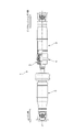
- FIG. 1 is a diagram showing a propeller shaft of Embodiment 1.
- FIG. 1 is a diagram showing a propeller shaft of Embodiment 1.
- the propeller shaft 1 includes a first propulsion shaft 2 connected to a differential gear (not shown), a stub shaft (second propulsion shaft) 3 connected to an output shaft of a transmission connected to an engine (not shown) that is a drive source, A constant velocity joint 4 connecting the first propulsion shaft 2 and the stub shaft 3 and a boot 5 sealing between the stub shaft 3 and the constant velocity joint 4 are provided.
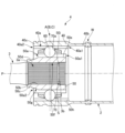
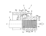
- FIG. 2 is a cross-sectional view of the constant velocity joint of Embodiment 1.
- FIG. 2 is a cross-sectional view of the constant velocity joint of Embodiment 1.
- the constant velocity joint 4 is held by an outer ring member 40, an inner ring member 50, a retainer 70 disposed between the outer ring member 40 and the inner ring member 50, and an open window portion 70a of the retainer 70. and a ball 60 that connects the inner ring member 50 .
- the tubular outer ring member 40 has a first outer ring end portion 40b on the first propelling shaft 2 side and a second outer ring end portion 40c on the second propelling shaft 3 side.
- the first outer ring end portion 40b is connected to the tubular first propulsion shaft 2 by a welded portion W.
- the inner circumference of the outer ring member 40 has a first outer ring groove end portion 40a1 on the first propulsion shaft 2 side and a second outer ring end portion 40a2 on the stub shaft 3 side. , forming an outer ring groove portion 40a in which a ball (ball member) 60 is disposed.
- the outer ring groove portion 40a has an outer ring groove neutral position A at which the ball 60 abuts between the first outer ring groove end portion 40a1 and the second outer ring groove end portion 40a2.
- the retainer 70 is provided on the inner peripheral side of the outer ring member 40 and has an open window portion 70 a that retains the balls 60 .
- the inner ring member 50 is provided on the inner peripheral side of the retainer 70 and connected to the stub shaft 3 .
- the outer circumference of the inner ring member 50 has a first inner ring groove end portion 50a1 on the first propelling shaft 2 side and a second inner ring groove end portion 50a2 on the stub shaft 3 side, and is inclined with respect to the rotation axis P of the constant velocity joint 4.
- the inner ring groove portion 50a is recessed to intersect with the outer ring groove portion 40a, has a bottom portion 50e and a wall portion 50h, and has an inner ring groove portion 50a in which the balls 60 are arranged.
- a small diameter portion 50c smaller in diameter than the bottom portion 50e of the recessed portion 50g of the recess 50a, and a jig engaging recess 50d smaller in diameter than the small diameter portion 50c are formed in the small diameter portion 50c.
- the inner ring groove portion 50a has an inner ring groove neutral position B that contacts the ball 60 between the first inner ring groove end portion 50a1 and the second inner ring groove end portion 50a2.
- a bottom portion 50e of the second inner ring groove end portion 50a2 of the inner ring groove portion 50a is formed with an arcuate recess portion 50g having a smaller diameter than the other bottom portion 50e of the inner ring groove portion 50a.
- the recessed portion 50g is formed so that the distance from the rotation axis P of the constant velocity joint 4 becomes smaller as it approaches the stub shaft 3 in the direction of the rotation axis P of the constant velocity joint 4 . Thereby, even when the ball 60 moves to the recessed portion 50g, it can slide smoothly.
- a through hole 50b is formed in the inner periphery of the inner ring member 50, and a female spline portion 50f and a snap ring engagement groove portion 50i are formed in the inner peripheral surface of the through hole 50b.
- the stub shaft 3 has a male spline portion 3a and a snap ring accommodating groove 3b for holding the snap ring S on the outer peripheral surface of the end portion.
- the male spline portion 3a of the stub shaft 3 and the snap ring housing groove 3b holding the snap ring S are inserted into the through hole 50b of the inner ring member 50, and the male spline portion 3a of the stub shaft 3 is inserted into the female spline portion 50f of the inner ring member 50.
- the stub shaft 3 and the inner ring member 50 are connected and fixed by engaging the outer periphery of the snap ring S with the snap ring engagement groove portion 50i of the inner ring member 50. As shown in FIG.
- the outer ring groove neutral position A of the outer ring groove portion 40a of the outer ring member 40 where the ball 60 is located and the inner ring groove neutral position B of the inner ring groove portion 50a of the inner ring member 50 are positions where the stress acting on the boot 5 is minimized. Thereby, the durability of the boot 5 can be ensured, and the durability of the constant velocity joint 4 can be improved.
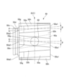
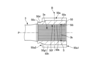
- FIG. 3 is a single part view of the inner ring member of the constant velocity joint of Embodiment 1.
- FIG. 3 is a single part view of the inner ring member of the constant velocity joint of Embodiment 1.
- the central inner ring groove portion 50a is recessed so that the center line Q is inclined clockwise with respect to the rotation axis P of the constant velocity joint 4 at an angle ⁇ .
- the inner ring groove portions 50a on both sides adjacent to the central inner ring groove portion 50a are recessed so that the center line Q is inclined counterclockwise at an angle ⁇ with respect to the rotation axis P of the constant velocity joint 4.
- adjacent inner ring groove portions 50a are provided so as to incline in opposite directions.
- the outer ring groove portion 40a indicated by the dashed line is inclined and recessed so as to intersect the rotation axis P of the constant velocity joint 4 and the central inner ring groove portion 50a.
- the outer ring groove portions 40a on both sides adjacent to the outer ring groove portion 40a are provided so as to incline in opposite directions, similarly to the inner ring groove portion 50a.
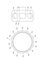
- FIG. 4 is a single part drawing of the retainer of the constant velocity joint of Embodiment 1.
- FIG. 4 is a single part drawing of the retainer of the constant velocity joint of Embodiment 1.
- the retainer 70 has eight windows 70a for holding the balls 60 having a width a in the circumferential direction and eight walls 70b partitioning the windows 70a having a width b in the circumferential direction.
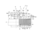
- FIG. 5 is a diagram showing a state of the constant velocity joint of Embodiment 1 at the time of collision. That is, at the time of a vehicle collision, the movement of the engine causes the stub shaft 3 and the inner ring member 50 to move in the F direction, and the ball 60 is positioned in the arcuate recess 50g of the second inner ring groove end portion 50a2 of the inner ring groove portion 50a. The ball 60 indicated by , has moved downward in the figure as indicated by the solid line from the position B in the inner ring groove neutral position.
- the diameter of the balls 60 contacting the side walls of the windows 70a of the retainer 70 can be reduced. That is, by reducing the diameter of the ball 60 that contacts the side wall of the window portion 70a of the retainer 70, the circumferential width b of the wall portion 70b is narrowed without widening the circumferential width a of the window portion 70a. Therefore, it is possible to increase the amount of sliding while maintaining the strength of the constant velocity joint 4, and only the inner ring member 50 needs to be machined, thereby suppressing an increase in machining cost.
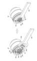
- FIG. 6 is a diagram showing a state before the stub shaft is attached to the constant velocity joint of Embodiment 1.
- the jig 100 Before assembling and fixing the stub shaft 3 in the next step to the constant velocity joint 4 assembled with the retainer 70 holding the outer ring member 40, the inner ring member 50, and the balls 60 in the windows 70a, the jig 100 is installed.
- the engaging portion 100a is engaged with the jig engaging concave portion 50d of the inner ring member 50, and the contacting portion 100b of the jig 100 is brought into contact with the outer ring member 40, so that the relative movement between the inner ring member 50 and the outer ring member 40 is prevented. I try to suppress it.
- the stub shaft 3 is inserted into the through hole 50b of the inner ring member 50 in the next process, in the constant velocity joint 4 assembled with the retainer 70 holding the outer ring member 40, the inner ring member 50, and the balls 60 in the windows 70a. Since it can be inserted, the assembling workability of the propeller shaft 1 can be improved, and the reliability can also be improved.
- the outer ring member 40 formed in a cylindrical shape and connected to the first propulsion shaft 2 is provided on the inner circumference of the outer ring member 40 and has a predetermined An outer ring member 40 in which an outer ring groove portion 40a formed with an angle is recessed, a ball member 60 disposed in the outer ring groove portion 40a, and a ball member 60 provided on the inner peripheral side of the outer ring member 40 to hold the ball member 60.
- a cage 70 provided with a window portion 70a, and an inner ring member 50 provided on the inner peripheral side of the cage 70 and connected to the second propulsion shaft 3, the outer circumference of the inner ring member 50 intersecting with the outer ring groove portion 40a.
- the inner ring groove portion 50a in which the ball member 60 is arranged and the bottom portion 50e of the second inner ring groove end portion 50a2 of the inner ring groove portion 50a are formed to have a smaller diameter than the other bottom portion 50e of the inner ring groove portion 50a.
- An inner ring member 50 having a recessed portion 50g is provided. Therefore, by dropping the balls 60 into the recessed portions 50g, the diameter of the balls 60 contacting the side walls of the windows 70a of the retainer 70 can be reduced. Without narrowing the circumferential width b of the wall portion 70b, the sliding amount can be increased while ensuring the strength of the constant velocity joint 4, and only the inner ring member 50 needs to be processed, resulting in processing costs. increase can be suppressed.
- the recessed portion 50g is formed on an arc. Therefore, even when the ball 60 moves to the recessed portion 50g, it can slide smoothly.
- the outer ring groove neutral position A of the outer ring groove portion 40a of the outer ring member 40 where the ball 60 is located and the inner ring groove neutral position B of the inner ring groove portion 50a of the inner ring member 50 are positions where the stress acting on the boot 5 is minimized. I made it Therefore, the durability of the boot 5 can be ensured, and the durability of the constant velocity joint 4 can be improved.
- a repair is performed.
- the engaging portion 100a of the jig 100 is engaged with the jig engaging concave portion 50d of the inner ring member 50, and the contact portion 100b of the jig 100 is brought into contact with the outer ring member 40, thereby separating the inner ring member 50 and the outer ring member 40. Suppresses relative movement.
- the stub shaft 3 is inserted into the through hole 50b of the inner ring member 50 in the next step. Since the work of (1) can be performed, disassembly and reassembly in the next process are not necessary, and the assembling workability of the propeller shaft 1 is improved. can be done.
- FIG. 7 is a cross-sectional view of an inner ring member of a constant velocity joint of Embodiment 2.
- the recessed portion 50g provided in the bottom portion 50e of the second inner ring groove end portion 50a2 of the inner ring groove portion 50a of the inner ring member 50 is arranged so that the distance from the rotation axis P of the constant velocity joint 4 is equal to the rotation axis of the constant velocity joint 4.
- the recessed portion 50g is formed in the arc shape that becomes smaller as it approaches the stub shaft 3, but in the second embodiment, the recessed portion 50g provided in the bottom portion 50e of the second inner ring groove end portion 50a2 of the inner ring groove portion 50a of the inner ring member 50 is formed.
- the distance from the rotation axis P of the constant velocity joint 4 is formed in a linear shape in which the distance from the rotation axis P of the constant velocity joint 4 decreases as the stub shaft 3 is approached. Since other configurations are the same as those of the first embodiment, the same configurations are denoted by the same reference numerals, and descriptions thereof are omitted. Therefore, in the second embodiment, in addition to the effects of the first embodiment except for the function and effect (2), there is a function and effect that processing can be facilitated.
- FIG. 8 is a cross-sectional view of a constant velocity joint of Embodiment 3.
- FIG. 8 is a cross-sectional view of a constant velocity joint of Embodiment 3.
- the arcuate depression 50g is provided only on the bottom 50e of the second inner ring groove end 50a2 of the inner ring groove 50a of the inner ring member 50.
- the arcuate depression 50g is provided on the inner ring member. 50 are provided on both the first inner ring groove end portion 50a1 of the inner ring groove portion 50a and the bottom portion 50e of the second inner ring groove end portion 50a2. Since other configurations are the same as those of the first embodiment, the same configurations are denoted by the same reference numerals, and descriptions thereof are omitted. Therefore, in addition to the effects of the first embodiment, the third embodiment has the effect of maximizing the amount of sliding of the constant velocity joint 4 .
- FIG. 9 is a cross-sectional view showing a state of the constant velocity joint of Embodiment 4 at the time of collision.
- the arcuate depression 50g is provided in the bottom 50e of the second inner ring groove end 50a2 of the inner ring groove 50a of the inner ring member 50, but in Embodiment 4, the depression 40e is provided in the outer ring groove of the outer ring member 40. It is provided at the bottom portion 40d of the first outer ring groove end portion 40a1 of 40a.
- the recessed portion 40e has a recessed shape in which the bottom portion 40d of the first outer ring groove end portion 40a1 of the outer ring groove portion 40a of the outer ring member 40 is formed to have a larger diameter than the other bottom portion 40d of the outer ring groove portion 40a. Since other configurations are the same as those of the first embodiment, the same configurations are denoted by the same reference numerals, and descriptions thereof are omitted. Therefore, the fourth embodiment has the same effect as the first embodiment.
- the recessed portion 40e provided in the first outer ring groove end portion 40a1 of the outer ring groove portion 40a of the outer ring member 40 of the fourth embodiment has a concave shape, but it may be formed in an arc shape as in the first embodiment, It may be formed linearly as in the second embodiment, or may be provided at both the first outer ring groove end portion 40a1 and the second outer ring groove end portion 40a2 of the outer ring groove portion 40a of the outer ring member 40 as in the third embodiment. .
- the present invention is not limited to the above-described embodiments, and includes various modifications.
- the above-described embodiments have been described in detail in order to explain the present invention in an easy-to-understand manner, and are not necessarily limited to those having all the configurations described.
- part of the configuration of one embodiment can be replaced with the configuration of another embodiment, and the configuration of another embodiment can be added to the configuration of one embodiment.
Landscapes
- Engineering & Computer Science (AREA)
- General Engineering & Computer Science (AREA)
- Mechanical Engineering (AREA)
- Ocean & Marine Engineering (AREA)
- Shafts, Cranks, Connecting Bars, And Related Bearings (AREA)
- Motor Power Transmission Devices (AREA)
Priority Applications (2)
| Application Number | Priority Date | Filing Date | Title |
|---|---|---|---|
| CN202280059442.6A CN117897564A (zh) | 2021-09-10 | 2022-07-07 | 传动轴用等速接头以及传动轴 |
| US18/689,333 US20250003454A1 (en) | 2021-09-10 | 2022-07-07 | Constant velocity joint for propeller shaft and propeller shaft |
Applications Claiming Priority (2)
| Application Number | Priority Date | Filing Date | Title |
|---|---|---|---|
| JP2021147400A JP2023040443A (ja) | 2021-09-10 | 2021-09-10 | プロペラシャフト用の等速ジョイントおよびプロペラシャフト |
| JP2021-147400 | 2021-09-10 |
Publications (1)
| Publication Number | Publication Date |
|---|---|
| WO2023037745A1 true WO2023037745A1 (ja) | 2023-03-16 |
Family
ID=85506535
Family Applications (1)
| Application Number | Title | Priority Date | Filing Date |
|---|---|---|---|
| PCT/JP2022/026935 Ceased WO2023037745A1 (ja) | 2021-09-10 | 2022-07-07 | プロペラシャフト用の等速ジョイントおよびプロペラシャフト |
Country Status (4)
| Country | Link |
|---|---|
| US (1) | US20250003454A1 (enExample) |
| JP (1) | JP2023040443A (enExample) |
| CN (1) | CN117897564A (enExample) |
| WO (1) | WO2023037745A1 (enExample) |
Citations (4)
| Publication number | Priority date | Publication date | Assignee | Title |
|---|---|---|---|---|
| JPH05231435A (ja) * | 1992-02-24 | 1993-09-07 | Ntn Corp | 等速自在継手 |
| JP2003056590A (ja) * | 2001-06-08 | 2003-02-26 | Ntn Corp | プロペラシャフト用等速自在継手 |
| JP2007232192A (ja) * | 2006-03-03 | 2007-09-13 | Ntn Corp | 固定式等速自在継手 |
| JP2009058074A (ja) * | 2007-08-31 | 2009-03-19 | Ntn Corp | ダブルオフセット型等速自在継手 |
-
2021
- 2021-09-10 JP JP2021147400A patent/JP2023040443A/ja not_active Abandoned
-
2022
- 2022-07-07 CN CN202280059442.6A patent/CN117897564A/zh active Pending
- 2022-07-07 WO PCT/JP2022/026935 patent/WO2023037745A1/ja not_active Ceased
- 2022-07-07 US US18/689,333 patent/US20250003454A1/en active Pending
Patent Citations (4)
| Publication number | Priority date | Publication date | Assignee | Title |
|---|---|---|---|---|
| JPH05231435A (ja) * | 1992-02-24 | 1993-09-07 | Ntn Corp | 等速自在継手 |
| JP2003056590A (ja) * | 2001-06-08 | 2003-02-26 | Ntn Corp | プロペラシャフト用等速自在継手 |
| JP2007232192A (ja) * | 2006-03-03 | 2007-09-13 | Ntn Corp | 固定式等速自在継手 |
| JP2009058074A (ja) * | 2007-08-31 | 2009-03-19 | Ntn Corp | ダブルオフセット型等速自在継手 |
Also Published As
| Publication number | Publication date |
|---|---|
| JP2023040443A (ja) | 2023-03-23 |
| CN117897564A (zh) | 2024-04-16 |
| US20250003454A1 (en) | 2025-01-02 |
Similar Documents
| Publication | Publication Date | Title |
|---|---|---|
| EP2716925B1 (en) | Constant velocity universal joint | |
| WO2012005087A1 (ja) | 固定式等速自在継手 | |
| JP2012017809A5 (enExample) | ||
| KR101994661B1 (ko) | 등속조인트용 케이지 및 그 케이지 및 슬리브 일체형 내륜을 갖는 등속조인트 | |
| EP1394430B2 (en) | Cross coupling | |
| EP1703157B1 (en) | Structure for preventing shaft of constant velocity joint from coming off | |
| WO2023037745A1 (ja) | プロペラシャフト用の等速ジョイントおよびプロペラシャフト | |
| US20250163971A1 (en) | Plunging-type constant velocity universal joint | |
| JP2010133442A (ja) | 固定型等速自在継手 | |
| JP6863785B2 (ja) | 固定式等速自在継手 | |
| WO2023037744A1 (ja) | プロペラシャフト用の等速ジョイントおよびプロペラシャフト | |
| JP2010133444A (ja) | 固定型等速自在継手 | |
| JP7058622B2 (ja) | プロペラシャフト | |
| KR20220099762A (ko) | 등속 조인트 | |
| JP2009074594A (ja) | 摺動型等速自在継手 | |
| US20080064509A1 (en) | Fixed Type Constant Velocity Universal Joint | |
| JPH11236926A (ja) | バーフィールド型等速自在継手 | |
| JP2008267533A (ja) | 固定式等速自在継手 | |
| JP2008240970A (ja) | 固定型等速自在継手 | |
| JP6904891B2 (ja) | 車両の等速自在継手 | |
| JP2008309221A (ja) | 固定式等速自在継手 | |
| JP2009103251A (ja) | 固定型等速自在継手 | |
| JP2009047236A (ja) | 固定型等速自在継手 | |
| JP2007010086A (ja) | 等速自在継手 | |
| JP7071854B2 (ja) | 等速自在継手 |
Legal Events
| Date | Code | Title | Description |
|---|---|---|---|
| 121 | Ep: the epo has been informed by wipo that ep was designated in this application |
Ref document number: 22867069 Country of ref document: EP Kind code of ref document: A1 |
|
| WWE | Wipo information: entry into national phase |
Ref document number: 202280059442.6 Country of ref document: CN |
|
| WWE | Wipo information: entry into national phase |
Ref document number: 18689333 Country of ref document: US |
|
| NENP | Non-entry into the national phase |
Ref country code: DE |
|
| 122 | Ep: pct application non-entry in european phase |
Ref document number: 22867069 Country of ref document: EP Kind code of ref document: A1 |