WO2023037697A1 - 物品管理システム、データ生成方法及び情報処理装置 - Google Patents
物品管理システム、データ生成方法及び情報処理装置 Download PDFInfo
- Publication number
- WO2023037697A1 WO2023037697A1 PCT/JP2022/025035 JP2022025035W WO2023037697A1 WO 2023037697 A1 WO2023037697 A1 WO 2023037697A1 JP 2022025035 W JP2022025035 W JP 2022025035W WO 2023037697 A1 WO2023037697 A1 WO 2023037697A1
- Authority
- WO
- WIPO (PCT)
- Prior art keywords
- user
- history
- article
- tag
- wireless device
- Prior art date
- Legal status (The legal status is an assumption and is not a legal conclusion. Google has not performed a legal analysis and makes no representation as to the accuracy of the status listed.)
- Ceased
Links
Images


Classifications
-
- G—PHYSICS
- G06—COMPUTING OR CALCULATING; COUNTING
- G06Q—INFORMATION AND COMMUNICATION TECHNOLOGY [ICT] SPECIALLY ADAPTED FOR ADMINISTRATIVE, COMMERCIAL, FINANCIAL, MANAGERIAL OR SUPERVISORY PURPOSES; SYSTEMS OR METHODS SPECIALLY ADAPTED FOR ADMINISTRATIVE, COMMERCIAL, FINANCIAL, MANAGERIAL OR SUPERVISORY PURPOSES, NOT OTHERWISE PROVIDED FOR
- G06Q10/00—Administration; Management
- G06Q10/02—Reservations, e.g. for tickets, services or events
-
- G—PHYSICS
- G01—MEASURING; TESTING
- G01S—RADIO DIRECTION-FINDING; RADIO NAVIGATION; DETERMINING DISTANCE OR VELOCITY BY USE OF RADIO WAVES; LOCATING OR PRESENCE-DETECTING BY USE OF THE REFLECTION OR RERADIATION OF RADIO WAVES; ANALOGOUS ARRANGEMENTS USING OTHER WAVES
- G01S5/00—Position-fixing by co-ordinating two or more direction or position line determinations; Position-fixing by co-ordinating two or more distance determinations
- G01S5/02—Position-fixing by co-ordinating two or more direction or position line determinations; Position-fixing by co-ordinating two or more distance determinations using radio waves
-
- G—PHYSICS
- G06—COMPUTING OR CALCULATING; COUNTING
- G06K—GRAPHICAL DATA READING; PRESENTATION OF DATA; RECORD CARRIERS; HANDLING RECORD CARRIERS
- G06K7/00—Methods or arrangements for sensing record carriers, e.g. for reading patterns
- G06K7/10—Methods or arrangements for sensing record carriers, e.g. for reading patterns by electromagnetic radiation, e.g. optical sensing; by corpuscular radiation
- G06K7/10009—Methods or arrangements for sensing record carriers, e.g. for reading patterns by electromagnetic radiation, e.g. optical sensing; by corpuscular radiation sensing by radiation using wavelengths larger than 0.1 mm, e.g. radio-waves or microwaves
- G06K7/10019—Methods or arrangements for sensing record carriers, e.g. for reading patterns by electromagnetic radiation, e.g. optical sensing; by corpuscular radiation sensing by radiation using wavelengths larger than 0.1 mm, e.g. radio-waves or microwaves resolving collision on the communication channels between simultaneously or concurrently interrogated record carriers.
- G06K7/10079—Methods or arrangements for sensing record carriers, e.g. for reading patterns by electromagnetic radiation, e.g. optical sensing; by corpuscular radiation sensing by radiation using wavelengths larger than 0.1 mm, e.g. radio-waves or microwaves resolving collision on the communication channels between simultaneously or concurrently interrogated record carriers. the collision being resolved in the spatial domain, e.g. temporary shields for blindfolding the interrogator in specific directions
- G06K7/10089—Methods or arrangements for sensing record carriers, e.g. for reading patterns by electromagnetic radiation, e.g. optical sensing; by corpuscular radiation sensing by radiation using wavelengths larger than 0.1 mm, e.g. radio-waves or microwaves resolving collision on the communication channels between simultaneously or concurrently interrogated record carriers. the collision being resolved in the spatial domain, e.g. temporary shields for blindfolding the interrogator in specific directions the interrogation device using at least one directional antenna or directional interrogation field to resolve the collision
- G06K7/10099—Methods or arrangements for sensing record carriers, e.g. for reading patterns by electromagnetic radiation, e.g. optical sensing; by corpuscular radiation sensing by radiation using wavelengths larger than 0.1 mm, e.g. radio-waves or microwaves resolving collision on the communication channels between simultaneously or concurrently interrogated record carriers. the collision being resolved in the spatial domain, e.g. temporary shields for blindfolding the interrogator in specific directions the interrogation device using at least one directional antenna or directional interrogation field to resolve the collision the directional field being used for pinpointing the location of the record carrier, e.g. for finding or locating an RFID tag amongst a plurality of RFID tags, each RFID tag being associated with an object, e.g. for physically locating the RFID tagged object in a warehouse
-
- G—PHYSICS
- G06—COMPUTING OR CALCULATING; COUNTING
- G06Q—INFORMATION AND COMMUNICATION TECHNOLOGY [ICT] SPECIALLY ADAPTED FOR ADMINISTRATIVE, COMMERCIAL, FINANCIAL, MANAGERIAL OR SUPERVISORY PURPOSES; SYSTEMS OR METHODS SPECIALLY ADAPTED FOR ADMINISTRATIVE, COMMERCIAL, FINANCIAL, MANAGERIAL OR SUPERVISORY PURPOSES, NOT OTHERWISE PROVIDED FOR
- G06Q10/00—Administration; Management
- G06Q10/06—Resources, workflows, human or project management; Enterprise or organisation planning; Enterprise or organisation modelling
-
- G—PHYSICS
- G06—COMPUTING OR CALCULATING; COUNTING
- G06Q—INFORMATION AND COMMUNICATION TECHNOLOGY [ICT] SPECIALLY ADAPTED FOR ADMINISTRATIVE, COMMERCIAL, FINANCIAL, MANAGERIAL OR SUPERVISORY PURPOSES; SYSTEMS OR METHODS SPECIALLY ADAPTED FOR ADMINISTRATIVE, COMMERCIAL, FINANCIAL, MANAGERIAL OR SUPERVISORY PURPOSES, NOT OTHERWISE PROVIDED FOR
- G06Q10/00—Administration; Management
- G06Q10/08—Logistics, e.g. warehousing, loading or distribution; Inventory or stock management
- G06Q10/087—Inventory or stock management, e.g. order filling, procurement or balancing against orders
Definitions
- the present disclosure relates to an article management system, a data generation method, and an information processing device.
- factories and construction sites use a variety of equipment (for example, vehicles or machines).
- equipment for example, vehicles or machines.
- the usage record that is, the information on who used which equipment.
- information such as the name of the user and the time of use has been recorded in a ledger.
- manual entry of information into the ledger has sometimes resulted in records being inconsistent with the facts, for example due to inaccuracies or omissions.
- Patent Document 1 an IC tag is mounted on a key for unlocking and locking a vault for storing articles, and based on the information read from the IC tag when the key is lent and returned, the history of key lending is obtained. is disclosed.
- Patent Document 1 the history recorded by the technique disclosed in Patent Document 1 indicates when and until when the user possessed the key, and indicates when and who used the item that can be used with the key. not.
- Such techniques are incomplete from the standpoint of keeping an accurate record of the use of goods, for example, even if a key that has been lent once is handed over to another user, the fact cannot be recognized.
- the present invention seeks to realize a mechanism for keeping highly accurate records regarding the use of goods.
- a first wireless device installed in a plurality of areas, a second wireless device attached to an article, a third wireless device carried by each of a plurality of users, and a wireless device from the wireless device at least one reader capable of reading identification information stored in a device; a history acquisition unit that acquires a location history and a movement history of each user based on results of reading identification information from the first wireless device and the third wireless device by the at least one reader; a generation unit that generates usage record data that associates the item with users who have used the item based on a comparison of the location history of the item and the movement history of one or more users. be done.
- a corresponding method and information processing apparatus are also provided.
- FIG. 1 is a schematic diagram showing an example of the configuration of an article management system according to one embodiment
- FIG. 1 is a block diagram showing an example of the configuration of a tag reader according to one embodiment
- FIG. FIG. 2 is a block diagram showing an example of the configuration of a management server according to one embodiment
- Explanatory drawing which shows an example of a structure of the goods table which concerns on one Embodiment.
- Explanatory drawing which shows an example of a structure of the area table which concerns on one Embodiment.
- 4 is an explanatory diagram showing an example of the configuration of a reader table according to one embodiment
- FIG. Explanatory drawing which shows an example of a structure of the user table which concerns on one Embodiment.
- FIG. 4 is an explanatory diagram showing an example of the configuration of a reading result table according to one embodiment
- FIG. 4 is an explanatory diagram for explaining acquisition of a position history of an article and a movement history of a user
- 4 is an explanatory diagram showing an example of the configuration of a reservation table according to one embodiment
- FIG. 4 is an explanatory diagram showing an example of the configuration of a usage history table according to one embodiment
- FIG. 11 is an explanatory diagram for explaining determination of usage record based on comparison of histories according to the first embodiment
- FIG. 11 is an explanatory diagram for explaining determination of a usage record based on comparison of histories according to the second embodiment
- 11 is an explanatory diagram for explaining determination of a usage record based on comparison of histories according to the third embodiment; 4 is a flowchart showing an example of the flow of position estimation processing according to one embodiment; 4 is a flowchart showing an example of the flow of history acquisition processing according to an embodiment; 4 is a flowchart showing a first example of the flow of usage record generation processing according to an embodiment; 9 is a flowchart showing a second example of the flow of usage history generation processing according to one embodiment;
- FIG. 1 is a schematic diagram showing an example of the configuration of an article management system 1 according to one embodiment.
- the article management system 1 is a system for managing the usage of articles by users.
- any type of article may be used by the user, and the article may be inanimate (for example, machine, equipment, instrument, material, consumer goods, parts, vehicle or robot) or living (for example, animal or plant).
- the space in which each user can be active is divided into multiple areas 10a to 10n.
- a user 20a and articles 30a and 30b are present in the area 10a.
- a user 20b exists in the area 10b. Users 20a and 20b can freely move between multiple areas 10a-10n.
- the article management system 1 utilizes wireless devices, also called tags, for the purpose of article management.
- the article management system 1 includes three types of tags.
- a first type of tag (first wireless device) is a location tag installed in each of the areas 10a-10n.
- a second type of tag (second wireless device) is an article tag attached to each article managed by the article management system 1 .
- a third type of tag (third wireless device) is a user tag carried by a user.
- location tags 40a to 40n are installed in areas 10a to 10n, respectively.
- the installation position of each of the position tags 40a-40n may be fixed or changeable.
- the position tag When the area itself moves (for example, the work site moves), the position tag may be moved along with the movement of the area.
- Article tags 50a and 50b are attached to the articles 30a and 30b, respectively. Each item tag moves as the corresponding item moves.
- the user 20a carries a user tag 60a.
- User 20b carries user tag 60b.
- the user tags 60a and 60b may be IC card-type devices such as employee ID cards or admission cards.
- the expression that the user carries some object broadly encompasses various modes in which the user moves with the object (for example, moves while holding or wearing the object). do.
- area 10 when it is not necessary to distinguish the areas 10a to 10n from each other, they are collectively referred to as area 10 by omitting the alphabet at the end of the code.
- articles 30 articles 30a, 30b
- location tags 40 40a-40n
- article tags 50 article tags 50a, 50b
- user tags 60 user tags 60a, 60b
- the number of users 20 and the number of items 30 existing in the item management system 1 are not limited to the example shown in FIG. 1, and may be any number.
- each of the tags such as the position tag 40, article tag 50, and user tag 60 is assumed to be a passive RFID (Radio Frequency Identification) tag (passive tag).
- a passive tag consists of a small IC (Integrated Circuit) chip with built-in memory and an antenna, and stores identification information and other information for identifying the tag in the memory.
- the identification information is simply referred to as an ID
- the identification information for identifying a tag is also referred to as a tag ID.
- the tag ID may be regarded as information that identifies the object to which the tag is attached.
- the IC chip of the passive tag operates using the energy of the electromagnetic wave emitted from the tag reader, modulates the tag ID and other information stored in the memory into an information signal, and transmits the information signal from the antenna. (return).
- item tags 50a and 50b have unique tag IDs 51a and 51b, respectively, embedded within the tags.
- the tag ID 51 of each article tag 50 is associated with the article 30 to which the article tag 50 is attached in a database described later.
- Each user tag 60 also has a unique tag ID embedded within the tag.
- the tag ID of each user tag 60 is associated with the user 20 carrying that user tag 60 .
- Each location tag 40 also has a unique tag ID embedded within the tag.
- the tag ID of each position tag 40 is associated with the area 10 in which the position tag 40 is installed.
- each tag may be an active RFID tag.
- a tag may be called a beacon tag if it actively (for example, periodically) transmits information to its surroundings using power from an internal battery.
- each tag may be a wireless device that returns information in response to a signal from the reader, eg, in Near Field Communication (NFC) or Bluetooth.
- NFC Near Field Communication
- Each tag may be called by any name such as an IC tag, an IC card, or a responder.
- the user 20a carries a tag reader 100a in addition to the user tag 60a.
- the user 20b carries a tag reader 100b in addition to the user tag 60b.
- each tag reader 100 can be carried by a user 20 to move between multiple areas 10a-10n.
- the article management system 1 includes at least one tag reader 100, a management server 200, and a terminal device 300 as described above. Note that each tag reader 100 need not be associated with a specific user 20 . For example, users 20 a and 20 b may exchange tag readers 100 a and 100 b with each other, or multiple users 20 may share a smaller number of tag readers 100 .
- Network 5 may be a wired network, a wireless network, or any combination thereof. Examples of network 5 may include the Internet, intranets and cloud networks.
- the tag reader 100 is a reader capable of reading information stored in a wireless device such as an RFID tag from the wireless device.
- the tag reader 100 can detect the article 30 by reading the tag ID 51 from the article tag 50 attached to the article 30 .
- the tag reader 100 performs reading periodically or in response to some trigger such as user operation, and transmits the tag reading result to the management server 200 .
- the tag reader 100 may communicate directly with the management server 200, or indirectly communicate with the management server 200 via some relay device (for example, a PC or smartphone carried by the user 20). good too.
- some relay device for example, a PC or smartphone carried by the user 20.
- the management server 200 is an information processing device that tracks the locations of the user 20 and the item 30 and records the usage of the item 30 by the user 20 in a database.
- the management server 200 may be implemented as an application server, database server, or cloud server using, for example, a high-performance general-purpose computer. An example of a specific configuration of the management server 200 will be further described later.
- management server 200 may be provided by a single device, or may be provided by a plurality of physically separate devices. It may be provided by cooperating. Also, in this embodiment, an example in which the management server 200 holds the database will be described, but a device separate from the management server 200 may hold part or all of the database. For example, some data may be held by the wireless device, tag reader 100 or terminal device 300 .
- the terminal device 300 is used by the user 20 or administrator of the article management system 1.
- the terminal device 300 may be, for example, a general-purpose terminal such as a PC (Personal Computer) or a smartphone, or may be a dedicated terminal specialized for the purpose of article management.
- the terminal device 300 may be portable or stationary.
- the terminal device 300 typically includes an input device that receives user input, a communication interface that communicates with other devices (for example, the management server 200), and a display device that displays information.
- the terminal device 300 is used when the user 20 registers a usage reservation for the article 30 with the management server 200 .
- the terminal device 300 is used when the administrator views usage record data, which can be provided from the management server 200 and will be described later.
- FIG. 1 depicts the tag reader 100 and the terminal device 300 as separate devices, an integrated device having the functions of both the tag reader 100 and the terminal device 300 may be provided.
- the terminal device 300 may be carried by the user 20 and relay communication between the tag reader 100 and the management server 200 .
- the functions of the management server 200 described in this embodiment may be implemented in the terminal device 300 .
- FIG. 2 is a block diagram showing an example of the configuration of the tag reader 100 according to one embodiment.
- the tag reader 100 includes a control section 111, a storage section 112, a communication section 113, a measurement section 114, a power supply 115, and a reading section .
- the control unit 111 consists of a memory that stores computer programs and one or more processors (eg, CPU or microcontroller) that execute computer programs.
- the control unit 111 controls all functions of the tag reader 100 described in this specification. For example, the control unit 111 causes the reading unit 116 to try to read an RFID tag within the tag reading range, and temporarily stores the read information and the reading time in the storage unit 112 as reading result data. In parallel with reading the RFID tag, the control unit 111 causes the measurement unit 114 to measure the position of the tag reader 100 and stores the measurement result in the storage unit 112 . Then, the control unit 111 sends the reading result data and the measurement result data stored in the storage unit 112 to the management server 200 via the communication unit 113 together with the reader identification information (also referred to as reader ID) that identifies the own device. Send.
- the reader identification information also referred to as reader ID
- the storage unit 112 may include any type of storage medium, such as a semiconductor memory such as ROM (Read Only Memory) or RAM (Random Access Memory), an optical disk, or a magnetic disk. In this embodiment, the storage unit 112 stores the reading result data, the measurement result data, and the reader ID of the tag reader 100 described above.
- ROM Read Only Memory
- RAM Random Access Memory
- the storage unit 112 stores the reading result data, the measurement result data, and the reader ID of the tag reader 100 described above.
- the communication unit 113 is a communication interface for the tag reader 100 to communicate with the management server 200.
- the communication unit 113 may be a WLAN interface that communicates with a WLAN (Wireless Local Area Network) access point, or a cellular communication interface that communicates with a cellular base station.
- the communication unit 113 may be a connection interface (for example, a Bluetooth (registered trademark) interface or a USB (Universal Serial Bus) interface) for connection with a relay device.
- the measurement unit 114 is a unit capable of measuring the position of the tag reader 100.
- the measurement unit 114 uses self-position estimation technology, also called PDR (Pedestrian Dead Reckoning), to measure the amount of relative movement of the tag reader 100 from a certain reference position, and control the measured amount of movement. Output to unit 111 .
- the reference position for measuring the relative movement amount may be, for example, the position of the tag reader 100 when the tag reader 100 is activated.
- a relative movement amount of the tag reader 100 can be treated as a relative position.
- the measurement unit 114 includes a triaxial acceleration sensor 114a, a gyro sensor 114b, and a geomagnetic sensor 114c.
- the triaxial acceleration sensor 114a measures the acceleration applied to the tag reader 100 in a device coordinate system unique to the tag reader 100 and outputs first sensor data.
- the gyro sensor 114b measures the angular velocity of the tag reader 100, that is, changes in the posture of the tag reader 100, and outputs second sensor data.
- the geomagnetic sensor 114c measures the azimuth of the tag reader 100 in real space and outputs third sensor data. Based on the sensor data from these sensors, the measurement unit 114 accumulates the acceleration while converting the direction of the acceleration of the tag reader 100 into the direction in the coordinate system of the real space, thereby measuring the relative movement amount of the tag reader 100. can do.
- the relative movement amount output from the measurement unit 114 to the control unit 111 may be a two-dimensional vector in the horizontal plane, or a three-dimensional vector including a component in the height direction.
- the position coordinates of the installation position of each position tag 40 are known and registered in the database. Therefore, the current absolute position (positional coordinates) of the tag reader 100 is determined based on the relative movement amount from the time when the tag reader 100 detects the positional tag 40 to the current time and the known positional coordinates of the positional tag 40. can be estimated.
- the management server 200 estimates the absolute position of the tag reader 100 will be mainly described. good too.
- the measurement unit 114 may measure the current geographical position of the tag reader 100 using GPS (Global Positioning System).
- the measurement unit 114 may perform base station positioning or wireless LAN positioning for estimating the current position using known position coordinates of a connected base station or wireless LAN access point.
- FIG. 2 shows an example in which the tag reader 100 includes the measurement unit 114
- the measurement unit 114 may be included in an external device capable of communicating with the tag reader 100 and carried by the user together with the tag reader 100. good.
- the tag reader 100 receives movement amount information indicating the relative movement amount measured by the measuring unit 114 from the external device.
- the power supply 115 includes a battery and a DC-DC converter, and supplies electric power to the control unit 111, the storage unit 112, the communication unit 113, the measurement unit 114, and the reading unit 116 of the tag reader 100 to operate the electronic circuits.
- the battery may be a primary battery or a rechargeable secondary battery.
- the tag reader 100 may have connection terminals for connecting the tag reader 100 to an external power source for charging the power source 115 .
- the reading unit 116 is a unit that can read the information stored in each of the tags such as the position tag 40, article tag 50, and user tag 60 described above.
- reader 116 includes RF controller 120 , power amplifier 121 , filter 122 , first coupler 123 , second coupler 124 , antenna 125 , power detector 126 and canceller 127 .
- the RF controller 120 outputs a transmission signal (for example, a signal modulated in the UHF band) from the TX terminal to the power amplifier 121 under the control of the control section 111 .
- the power amplifier 121 amplifies the transmission signal input from the RF controller 120 and outputs it to the filter 122 .
- the amplification factor of the transmission signal here may be variably controllable, and the higher the amplification factor, the higher the output intensity of the electromagnetic waves radiated from the tag reader 100 .
- the filter 122 may be a low-pass filter, for example, and removes unnecessary low-frequency components of the transmission signal amplified by the power amplifier 121 .
- the first coupler 123 distributes the transmission signal that has passed through the filter 122 to the coupler 124 and the power detector 126 .
- the second coupler 124 outputs the transmission signal input from the first coupler 123 to the antenna 125 and outputs the reception signal input from the antenna 125 to the RF controller 120 .
- Antenna 125 transmits the transmission signal input from coupler 124 into the air as electromagnetic waves.
- the antenna 125 receives a signal returned from an RFID tag existing within the reading range of the tag reader 100 as a response to the transmitted signal, and outputs the received signal to the coupler 124 .
- antenna 125 may be an omni-directional antenna.
- antenna 125 may be a directional antenna with variably controllable beam direction.
- Power detection section 126 detects the power level of the signal input from first coupler 123 and outputs signal RF_DETECT indicating the detected power level to control section 111 .
- Canceller 127 receives signal CARRIER_CANCEL indicating the power level of the carrier wave from control unit 111 .
- the canceller 127 extracts the desired signal component of the received signal to be output to the RX terminal of the RF controller 120 by canceling the carrier wave component of the transmission signal based on CARRIER_CANCEL.
- the RF controller 120 demodulates the signal input from the RX terminal, acquires the tag ID and other information returned from the RFID tag, and outputs the acquired information to the control unit 111 . Further, RF controller 120 measures the reception level (also referred to as reception strength) of the signal input from the RX terminal and outputs the measurement result to control section 111 .
- reading unit 116 may attempt to read tags periodically (eg, once every second) without requiring explicit instructions from the user.
- the transmission of data from the communication unit 113 to the management server 200 can also be performed periodically (for example, once every few seconds) or each time the tag is read without requiring an explicit instruction by the user.
- the control unit 111 may exclude, from the data to be transmitted, records that are the same as the records that have been transmitted within the most recent predetermined period. .
- the control unit 111 determines that the RFID tag has been detected, and sends the read result data of the detected RFID tag to the management server. 200.
- one or both of the attempt to read the tag by the reading unit 116 and the transmission of data to the management server 200 are detected via an input device (e.g., button) provided on the tag reader 100. It may be performed according to a user operation.
- an input device e.g., button
- communication unit 113 indirectly communicates with management server 200 via a relay device, data transmission to management server 200 is performed only while the connection between communication unit 113 and the relay device is valid.
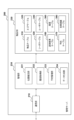
- FIG. 3 is a block diagram showing an example of the configuration of the management server 200 according to one embodiment.
- the management server 200 includes a communication section 210 , an article database (DB) 220 and a management section 230 .
- DB article database
- the communication unit 210 is a communication interface for the management server 200 to communicate with other devices.
- the communication unit 210 may be a wired communication interface or a wireless communication interface.
- the communication unit 210 communicates with the tag reader 100 and the terminal device 300 .
- the article DB 220 is a database that stores various information for tracking the positions of the user 20 and the article 30 and grasping the usage status of the article 30 .
- the article DB 220 includes an article table 310, an area table 320, a reader table 330, a user table 340, a reading result table 350, a history table 360, a reservation table 370, and a usage record table 380.
- the management unit 230 is a set of software modules that provide management functions for managing data in the article DB 220 .
- the individual software modules may operate by one or more processors (not shown) of management server 200 executing computer programs stored in memory (not shown).
- the management section 230 includes a position estimation section 231 , a history acquisition section 232 , a reservation management section 233 and a data generation section 234 .
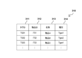
- Configuration of master data> 4A and 4B respectively show examples of configurations of the article table 310 and the area table 320 of the article DB 220.
- the item table 310 has four data items: tag ID 311, item ID 312, name 313, and type 314.
- the tag ID 311 is identification information that uniquely identifies the article tag 50 attached to each article 30 under the control of the system.
- the value of the tag ID 311 is the same as the tag ID value internally stored in the corresponding article tag 50 .
- the article ID 312 is identification information that uniquely identifies each article 30 .
- the name 313 represents the name of each item 30 .
- the items identified by the item IDs "IT01", “IT02” and “IT03” are given the names “item A", “item B" and “item C", respectively.
- article A" may correspond to the article 30a shown in FIG.
- Type 314 represents the type into which each item 30 is classified.
- the type of "goods A” and “goods C” is "Type 1”
- the type of "goods B” is "Type 2”.
- the values of the name 313 and type 314 of each item 30 may be determined by the user and registered in advance via a user interface (UI) provided by the management unit 230 .
- the values of name 313 and type 314 may be stored as item-related information on item tag 50 and read by tag reader 100 .
- the management server 200 receives the values of the name 313 and type 314 of the article 30 from the tag reader 100 and registers them in the article table 310 in response to the initial tag reading from the article tag 50 of each article 30 . can.
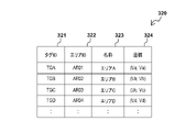
- the area table 320 has four data items: tag ID 321, area ID 322, name 323, and coordinates 324.
- the tag ID 321 is identification information that uniquely identifies the position tag 40 installed in each of the multiple areas 10 .
- the value of the tag ID 321 is the same as the tag ID value internally stored in the corresponding position tag 40 .
- the area ID 322 is identification information that uniquely identifies each area 10 .
- a name 323 represents the name of each area 10 .
- the areas identified by the area IDs "AR01”, “AR02”, “AR03” and “AR04" are respectively "area A", "area B", "area C” and "area D". is given the name.
- These names may actually be, for example, "construction section X", "floor Y", or "warehouse Z”.
- Coordinates 324 represent the position coordinates of the installation position of the position tag 40 installed in each area 10 .
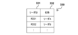
- 5A and 5B show examples of configurations of the reader table 330 and the user table 340, respectively.
- the reader table 330 has two data items, a reader ID 331 and a name 332.
- the reader ID 331 is identification information that uniquely identifies each tag reader 100 used in the system.
- Name 332 represents the name of each tag reader.
- the tag readers 100 identified by the reader IDs "RD01” and “RD02” are given the names “reader A” and “reader B", respectively.
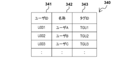
- the user table 340 has three data items: user ID 341, name 342, and tag ID 343.
- the user ID 341 is identification information that uniquely identifies each user 20 who uses the item 30 in the item management system 1 .
- Name 342 represents the name of each user. In the example of FIG. 5B, the name of the user 20 identified by the user ID "U001" is "user A”, the name of the user 20 identified by the user ID "U002" is “user B”, and the user ID "U003". The name of the identified user 20 is "user C”.
- the tag ID 343 is identification information that uniquely identifies the user tag 60 carried by each user 20 . The value of the tag ID 343 is the same as the tag ID value stored internally by the corresponding user tag 60 .
- user table 340 may have additional data items that hold authentication information (e.g., passwords or biometrics) for user authentication when logging into the system. .
- the reading result table 350 is a table for storing records of reading result data received from the tag reader 100 (hereinafter referred to as reading result records).
- FIG. 5C shows an example of the configuration of the reading result table 350.
- the reading result table 350 has four data items: reading time 351 , tag ID 352 , reader ID 353 and coordinates 354 .
- the read time 351 represents the time when the tag ID was read for each read result record.
- Tag ID 352 represents the tag ID read for each read result record.
- the reader ID 353 is identification information that identifies the tag reader 100 that has read the tag for each read result record. In the example of FIG.
- the first record of the reading result table 350 indicates that the tag reader 100a identified by the reader ID "RD01” reads the tag ID "TGA” (for example, the tag ID of the position tag 40a) at time "T01". is read.
- the second record indicates that the tag reader 100a read the tag ID "TGU1" (for example, the tag ID of the user tag 60a of the user 20a) at time "T02”.
- the third record indicates that tag reader 100a read tag ID "TG01" (for example, tag ID of article tag 50a of article 30a) at time "T03".
- Coordinates 354 represent the location coordinates of the point where the tag reader 100 was at the time the tag was read.
- the position estimating unit 231 determines that the user 20 associated with the read tag ID was present at the reading time indicated by the reading result data. Estimate location. User position estimation is performed using measurement result data periodically received from the tag reader 100 . For example, it is assumed that the tag reader 100a reads the tag ID of the position tag 40a at reading time T01 (first time point) and then reads the tag ID of the user tag 60a at reading time T02 (second time point).
- the amount of relative movement of the tag reader 100a from the reading time T01 to the reading time T02 corresponds to the difference in the amount of movement measured by the tag reader 100a at two points in time, and the position estimator 231 calculates this difference based on the measurement result data.
- the coordinates of the installation position of the position tag 40a installed in the area 10a are known and defined in the area table 320.
- FIG. Therefore, the position estimator 231 adds the relative movement amount of the tag reader 100a from the reading time T01 to the reading time T02 to the known position coordinates of the position tag 40a.
- Position can be estimated.
- the position estimation unit 231 additionally writes the position coordinates of each user 20 estimated in this way in the column of the coordinates 354 of the corresponding record of the reading result table 350 .
- the position estimating section 231 determines that the article 30 associated with the read tag ID exists at the reading time indicated by the reading result data. Estimate the position where the Item location estimation is also performed using measurement data received periodically from the tag reader 100 . For example, after the tag reader 100a reads the tag ID of the position tag 40a at reading time T01 (first time), it reads the tag ID of the article tag 50a attached to the article 30a at reading time T03 (third time).
- the relative movement amount of the tag reader 100a from the reading time T01 to the reading time T03 corresponds to the difference between the movement amounts measured by the tag reader 100a at two points in time, and the position estimator 231 calculates this difference based on the measurement result data. can be derived. Then, the position estimating unit 231 adds the relative movement amount of the tag reader 100a from the reading time T01 to the reading time T03 to the known position coordinates of the position tag 40a, thereby determining whether the article 30a existed at the reading time T03. Position can be estimated. The position estimation unit 231 additionally writes the position coordinates of each article 30 estimated in this way in the column of the coordinates 354 of the corresponding record in the reading result table 350 .
- the history acquisition unit 232 periodically acquires the history of the position of each article 30 and the history of movement of each user 20 from the reading result table 350 .
- the history acquisition unit 232 executes a process for acquiring the position history of each article 30 and the movement history of each user 20 each time a predefined period elapses, and obtains the acquired position history and movement history.
- the predefined time period may have any length, for example several hours, half a day or a day.
- the history acquisition unit 232 acquires the position history of the article 30 to which the article tag 50 is attached based on the result of reading the tag IDs from the position tag 40 and the article tag 50 by the tag reader 100. . Also, the history acquisition unit 232 acquires the movement history of the user 20 carrying the user tag 60 based on the result of reading the tag ID from the position tag 40 and the user tag 60 by the tag reader 100 .
- the position history of each article 30 is data indicating in which area 10 each article 30 was located in chronological order.
- the movement history of each user 20 is data indicating in which area each user 20 was located in chronological order.
- FIG. 6 is an explanatory diagram for explaining acquisition of position history and movement history by the history acquisition unit 232.
- FIG. The upper part of FIG. 6 shows only a part of exemplary contents of the reading result table 350 .
- the tag ID "TGU1" was read from the user tag 60a of the user 20a, and it is estimated that the user 20a was located at the position coordinates (U11, V11) at that time. shall have been Also, at 8:02 am on the same day, the tag ID "TG01" was read from the article tag 50a of the article 30a, and it was estimated that the article 30a was located at the position coordinates (U12, V12) at that time. do.
- the history table 360 has three data items: object 361 , time 362 and area 363 .
- the target 361 indicates the article ID of the article 30 or the user ID of the user 20 associated with each history record (hereinafter referred to as history record).
- the time 362 represents the representative time (for example, the start time) of each section (for example, having a time length of several minutes, several tens of minutes, or one hour) obtained by dividing the above-described period into shorter sections.
- the area 363 indicates in which area 10 the article 30 or the user 20 identified by the value of the target 361 existed in the corresponding section by the area ID or name of the area 10 .
- the history acquisition unit 232 extracts from the reading result table 350 the reading result record for the article 30a indicating the reading time belonging to a certain section. If there is no corresponding read result record, the history acquisition unit 232 may determine that the position of the article 30a in that section is unknown, and generate a history record with the area 363 blank. When one or more applicable reading result records are extracted, the history acquisition unit 232 determines, for example, which area 10 the position coordinates indicated by those reading result records belong to. Then, the history acquisition unit 232 can determine, for example, the area 10 corresponding to the largest number of read result records as the area 10 in which the article 30a existed in that section. In the example of FIG.
- the coordinates (U12, V12) of the estimated position of the article 30a at 8:02 a.m. belong to area A. It is determined that the article 30a (article A) existed in area A at . Further, since the coordinates (U11, V11) of the estimated position of the user 20a at 8:01 am belong to the area A, the user 20a It is determined that (user A) was in area A.
- the determination of which area 10 a certain position coordinate belongs to may be made based on, for example, the distance between the position coordinate and the known coordinates of the position tag 40 of each area 10 . As an example, if the position tag 40a among the plurality of position tags 40 is closest to the position coordinates (U12, V12), then the position coordinates (U12, V12) are said to belong to the area 10a associated with the position tag 40a. can be determined. As another example, the radius of each area 10 is predefined in the area table 320, and if the position coordinates fall within the circle defined by the position coordinates of the position tag 40 and the radius of the area 10, the position coordinates 10 may be determined.
- information representing the boundary of each area 10 may be defined in advance in the area table 320 .
- the position coordinates fall inside the boundary of the defined area 10, the position coordinates can be determined to belong to the area 10 in question.
- the determination of which area 10 the user 20 or the article 30 was located may be made without relying on the position coordinates of those objects.
- a position tag 40 is installed at the gate of each area 10 and the tag ID of the position tag 40 is always read by the tag reader 100 carried by the user 20 when entering/exiting each area 10 .
- the history acquisition unit 232 can determine the area 10 in which the user 20 or the article 30 existed from the detection history of the position tag 40 (for example, the time from entering to exiting the area 10 where the target is located). while the target is in its area 10).
- the reservation management unit 233 manages reservation data indicating reservations for use of the goods 30 in the reservation table 370 of the goods DB 220 .
- the reservation management unit 233 provides a UI for accepting reservation registration (for example, a reservation registration screen) to the user 20 or the administrator via the terminal device 300, and the reservation data input via the provided UI. may be registered in the reservation table 370.
- the reservation management unit 233 may provide the user 20 or the administrator via the terminal device 300 with a UI that enables browsing, correction, or deletion of registered reservation data.
- FIG. 7A shows an example of the configuration of the reservation table 370 of the article DB 220.
- the reservation table 370 has four data items: reservation ID 371 , period 372 , target item 373 and reservation person 374 .
- the reservation ID 371 is identification information that uniquely identifies each record of the reservation table 370 (hereinafter referred to as a reservation record).
- the period 372 indicates which period each reservation record covers.
- the target item 373 indicates which item 30 is targeted by each reservation record by the item ID of the item 30 .
- the reservation person 374 indicates the user 20 who is scheduled to use the item 30 represented by the target item 373 during the period represented by the period 372 by the user ID of the user 20 .
- a UI that enables such registration, viewing, correction, or deletion of reservation data may be configured by any method known to those skilled in the art, and therefore description thereof is omitted here.
- the data generator 234 associates the item 30 with the user 20 who used the item 30 based on a comparison between the location history of the item 30 and the movement history of one or more users 20 stored in the history table 360. Generate usage data. For example, the data generation unit 234 generates usage record data for each article 30 for the elapsed period each time a predefined period elapses, and stores the generated usage record data in the usage record table 380 .
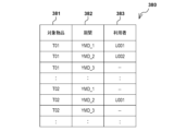
- FIG. 7B shows an example of the configuration of the usage record table 380 of the article DB 220. As shown in FIG.
- the usage record table 380 has three data items: target item 381 , period 382 and user 383 .
- Each record of the usage record table 380 indicates which user 20 used each item 30 in each period by combining the values of the target item 381 , period 382 and user 383 .
- the data generator 234 may allow the user 20 or the administrator to view the generated usage record data via the terminal device 300, for example.
- the data generation unit 234 may output usage record data for a specific period to a data file and transmit it to another device.
- the data generation unit 234 determines that the user 20 having the highest correlation with the position history of each article 30 (hereinafter referred to as the target article) in a certain period (hereinafter referred to as the target period) is the user 20 during the target period. can be determined to be the user who used the target item in. For example, for each user, the data generation unit 234 determines the matching degree of the time-based area where the user existed during the target period with respect to the time-based area where the target article existed during the target period. Then, the data generation unit 234 determines the users who used the target article during the target period based on the degree of matching determined for each user. At this time, the higher the determined degree of matching, the higher the correlation between the location history and the movement history can be evaluated. Therefore, in principle, it is determined that the user exhibiting the highest matching degree of history is the user who used the target product during the target period.
- the data generation unit 234 may further determine the degree of discrepancy between the time-based area where the user was present during the target period and the time-based area where the target article was present during the target period. Then, the data generation unit 234 may determine that a user whose determined degree of disagreement exceeds the reference value is not a user who used the target product during the target period, regardless of the degree of match in the history. That is, the correlation between location history and movement history may be rated lower the higher the discrepancy that is determined.
- the reference value to be compared with the non-matching degree may be, for example, a predefined fixed value or a product of the matching degree multiplied by a certain coefficient ⁇ (0 ⁇ 1).
- FIG. 8 is an explanatory diagram for explaining the determination of the usage history based on the history comparison according to the first embodiment.
- the target article is article A.
- the target period from 8:00 a.m. to noon on a certain date is divided into a total of eight sections, and the start times of these sections are shown in the second column from the left in FIG. 8 (hereinafter referred to as the time column).
- the time column there is To the left of the time column, the location history of item A that can be obtained from the history table 360 is shown. , 7th and 8th intervals.
- To the right of the time column movement histories of user A, user B, and user C that can be acquired from the history table 360 are shown.
- the data generation unit 234 identifies one or more users whose movement history includes the area included in the position history of the target article, and makes these users the targets of history comparison.
- the number of areas included in the location history is large (three areas A, B, and C in the example of FIG. 8)
- only a predetermined number of areas in descending order of the number of appearances in the location history are selected from the candidate users. May be used for primary filtering.
- the movement history of user C does not include any area described in the position history of article A, user C is excluded from history comparison targets.
- the number of article detections is the number of times the target article has been detected by the tag reader 100 (the number of times per section).
- the number of times of article detection is six.
- the number of matches is the number of sections in which the area matches between the position history of the target article and the movement history of each candidate user.
- User A is detected in the same area as the target article in five sections indicated by black circles in the figure, so the number of matches for user A is five.
- User B is detected in the same area as the target article in three sections indicated by black circles in the figure, so the number of matches for user B is three.
- the number of discrepancies is the number of sections in which the areas do not match between the position history of the target article and the movement history of each candidate user. It should be noted that sections in which at least one of the areas of the position history and movement history is blank may be ignored in the totalization. As for user A, since there is no section in which the areas do not match, the number of mismatches for user A is zero. User B is detected in an area different from the target article in the two sections indicated by X marks in the figure, so the number of discrepancies for user B is two.
- the data generation unit 234 may generate usage record data further based on the reservation data held in the reservation table 370 .
- Considering reservation data in determining usage history can reduce computational load by avoiding cross-comparison of multiple histories, or reduce accuracy when there are multiple users 20 exhibiting similar correlations. can make high-level decisions.
- the data generation unit 234 first generates the specified item 30 for the location history of the item 30 of users 20 may be compared. Then, when the correlation between these histories satisfies a predetermined criterion, it is determined that the specific user 20 used the item 30 during the target period without considering the movement histories of other users 20. good too.
- the predetermined criterion here may include that the degree of matching between the histories described above exceeds a certain reference value, and may further include that the degree of non-matching between the histories does not exceed another reference value.
- the user 20 registered as the user of the item 30 has a high probability of actually using the item 30 according to the reservation.
- Such an approach thus makes it possible in many cases to avoid the primary filtering of candidate users and the computation and inter-comparison of statistics for multiple users 20 . If the correlation between the movement history of the user 20 who is the reservation person and the location history of the target item does not satisfy the criteria, the remaining users 20 are temporarily filtered, and statistical values for the candidate users are calculated and compared with each other. , the user 20 who used the target item may be determined.
- FIG. 9 is an explanatory diagram for explaining the determination of the usage record based on the history comparison according to the second embodiment.
- the target article is article C.
- a target period (YMD_1) from 8:00 am to 12:00 noon on a certain date is divided into a total of eight sections, and the start times of these sections are indicated in the time column.
- the position history of article C is shown on the left of the time column, and the movement history of user D, user E, and user A is shown on the right of the time column.
- FIG. 9 partially shows the reservation data registered in the reservation table, and this reservation data indicates that the user D was scheduled to use the article C during the target period. Therefore, the data generator 234 first compares the movement history of the user D who made the reservation with the position history of the article C.
- the data generation unit 234 determines that one of the candidate users was the person who reserved the target item. may preferentially determine that the user indicated by the reservation data has used the target article. Since it is highly probable that the user 20 registered as the user of the item 30 will actually use the item 30 according to the reservation, such a method can determine with high accuracy the actual use record that matches the fact. .
- FIG. 10 is an explanatory diagram for explaining the determination of the usage history based on the history comparison according to the third embodiment.
- the target article is article A.
- a target period (YMD_2) from 13:00 to 17:00 on a certain date is divided into a total of eight sections, and the start times of these sections are indicated in the time column.
- the position history of the article A is shown on the left side of the time column, and the movement histories of the users A, B, and C are shown on the right side of the time column.
- the data generation unit 234 identifies one or more users whose movement history includes the area included in the position history of the target article, and makes these users the targets of history comparison.
- reservation data already registered in the reservation table is partially shown, and this reservation data indicates that user B was scheduled to use item A during the target period. Therefore, the data generation unit 234 can determine that the user B used the item A during the target period based on the correlation between histories and the usage reservation during the target period.
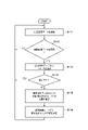
- FIG. 11 is a flowchart showing an example of the flow of position estimation processing mainly performed by the position estimation unit 231 of the management server 200. As shown in FIG. The position estimation process of FIG. 11 can be repeatedly executed while at least one tag reader 100 is operating in the article management system 1.
- FIG. 11 is a flowchart showing an example of the flow of position estimation processing mainly performed by the position estimation unit 231 of the management server 200. As shown in FIG. The position estimation process of FIG. 11 can be repeatedly executed while at least one tag reader 100 is operating in the article management system 1.
- FIG. 11 is a flowchart showing an example of the flow of position estimation processing mainly performed by the position estimation unit 231 of the management server 200. As shown in FIG. The position estimation process of FIG. 11 can be repeatedly executed while at least one tag reader 100 is operating in the article management system 1.
- FIG. 11 is a flowchart showing an example of the flow of position estimation processing mainly performed by the position estimation unit 231 of the management server 200. As shown in FIG. The position estimation process of FIG.
- the position estimation unit 231 receives measurement result data transmitted from the tag reader 100 via the communication unit 210 .
- the position estimation unit 231 waits for reception of reading result data from the tag reader 100 in parallel with reception of measurement result data. If read result data has been received from the tag reader 100, the process proceeds to S113. If the read result data is not received, the process returns to S111.
- the position estimation unit 231 adds a record corresponding to the read result data received from the tag reader 100 to the read result table 350 . Processing thereafter branches at S114 depending on whether the received read result data indicates that the tag ID of the position tag 40 has been read. If the tag ID of the position tag 40 has been read, the process returns to S111. If the tag ID of the article tag 50 or the user tag 60 is read instead of the position tag 40, the process proceeds to S115.
- the position estimating unit 231 calculates the position of the tag reader 100 at (or near) the reading time indicated by the received reading result data as the position of the tag reader 100 from when the same tag reader 100 detected the position tag 40. It is derived based on the amount of relative movement. The position derived here can be represented by the sum of the known position coordinates of the position tag 40 detected at a certain point in time and the amount of relative movement of the tag reader 100 from that point in time that can be calculated from the measurement result data. Then, the position estimation unit 231 estimates that the detected object (the article 30 attached with the article tag 50 or the user 20 carrying the user tag 60) is located at the derived position. Next, in S116, the position estimation unit 231 adds the position coordinates of the estimated position of the detected target to the column of coordinates 354 of the reading result record added to the reading result table 350 in S113. Then, the process returns to S111.
- FIG. 12 is a flowchart showing an example of the flow of history acquisition processing mainly executed by the history acquisition unit 232 of the management server 200. As shown in FIG. The history acquisition process in FIG. 12 can be executed for an elapsed period, for example, each time a period of several hours, half a day, or one day elapses.
- the history acquisition process consists of repetition (loop) of history acquisition for each section included in the target period.
- An interval treated in one iteration is referred to herein as a target interval.
- the history acquisition unit 232 extracts from the reading result table 350 the reading result record having the reading time belonging to the target section.
- the history acquisition unit 232 starts repetition (sub-loop) of history acquisition with each of the plurality of users 20 as the target user.
- the history acquisition unit 232 further extracts a record indicating the tag ID of the user tag 60 of the target user from the reading result record acquired in S122.
- the history acquisition unit 232 determines the area 10 in which the target user was present in the target section based on the value of the position coordinates of the extracted reading result record (detection position of the user tag 60). For example, the history acquisition unit 232 may determine that the target user exists in the area 10 associated with the position tag 40 installed closest to the detection position of the user tag 60 .
- the history acquisition unit 232 if the detection position of the user tag 60 falls within a certain area 10 determined by the definition of a simple area radius or the definition of a boundary having a more complicated shape, the target user existed in the area 10.
- the history acquisition unit 232 may determine the area 10 where the target user was present based on the values of the position coordinates of the reading result records by majority voting. good.
- the history acquisition unit 232 adds to the history table 360 a history record including the user ID of the target user, the time representing the target section, and the area ID or name of the area 10 determined in S ⁇ b>125 . If it is determined that acquisition of such movement histories has been completed for all target users (S127), the process proceeds to S130.
- the history acquisition unit 232 starts repetition (sub-loop) of history acquisition with each of the plurality of articles 30 as the target article.
- the history acquisition unit 232 further extracts a record indicating the tag ID of the article tag 50 of the target article from the read result record acquired in S122.
- the history acquisition unit 232 determines the area 10 in which the target article was present in the target section based on the value of the position coordinates of the extracted reading result record (the detection position of the article tag 50).
- the area determination method here may be the same as the method described in relation to S125.
- the history acquisition unit 232 adds to the history table 360 a history record including the item ID of the target item, the time representing the target section, and the area ID or name of the area 10 determined in S ⁇ b>132 .
- the process proceeds to S136.
- the history acquisition unit 232 determines whether there are unprocessed sections remaining in the target period, and if there are unprocessed sections remaining, the processing steps of S122 to S134 are executed for the next section. When it is determined that the acquisition of histories for all sections has been completed, the history acquisition process of FIG. 12 ends.
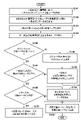
- FIGS. 13 and 14 are flowcharts showing an example of the flow of usage record generation processing mainly executed by the data generation unit 234 of the management server 200.
- FIG. For example, similar to the history acquisition process described above, the usage record generation process can be periodically executed each time the target period elapses. Although the usage history generation process can be repeated for each item 30 under the control of the system, FIGS. 13 and 14 only show the flow of processing for a single target item for the sake of clarity of explanation. .
- the data generation unit 234 determines the degree of match and the degree of mismatch between the position history of the target item and the movement history of each of the candidate users identified in S141.
- the data generation unit 234 selects candidate users whose degree of matching determined in S142 exceeds the first reference value.
- the data generation unit 234 excludes candidate users whose degree of disagreement determined in S142 exceeds a second reference value (lower than the first reference value) from the candidate users selected in S143.
- the data generator 234 determines whether at least one selected candidate user remains. If there are no selected candidate users remaining, the process proceeds to S146. On the other hand, if at least one selected candidate user remains, the process proceeds to S147.
- the data generation unit 234 determines that no user 20 used the target product during the target period. Then, the process proceeds to S152.
- the data generation unit 234 determines whether there are multiple candidate users with the highest degree of matching among the remaining candidate users. If there is only one candidate user with the highest degree of matching, the process proceeds to S148. On the other hand, if there are multiple candidate users with the highest degree of matching, the process proceeds to S149.
- the data generation unit 234 determines that the candidate user with the highest degree of matching used the target product during the target period. Then, the process proceeds to S152.
- the data generation unit 234 refers to the reservation data for the target item during the target period, and determines whether the remaining candidate users include the person who planned to use the target item. If the remaining candidate users do not include the reservation person, the process proceeds to S150. On the other hand, if the remaining candidate users include the reservation person, the process proceeds to S151.
- the data generation unit 234 determines the user 20 who has used the target item among the remaining candidate users according to some other conditions. For example, the data generator 234 may determine that all of the remaining candidate users "may" have used the target product during the target period. Then, the process proceeds to S152.
- the data generation unit 234 determines that the reservation person who was planning to use the target item actually used the target item during the target period. Then, the process proceeds to S152.
- the data generation unit 234 generates a record of the usage history of the target article for the target period according to the determination at S146, S148, S150 or S151, and adds the generated record to the usage history table 380.
- the data generation unit 234 determines whether there is a reservation for using the target article during the target period by referring to the reservation table 370. . If there is no usage reservation, the process proceeds to S165. If there is a reservation for use, the process proceeds to S161.
- the data generation unit 234 identifies the reservation person indicated by the reservation record of the reservation table 370 as the first candidate user whose history comparison should be preferentially performed.
- the data generator 234 determines the degree of matching and the degree of mismatching between the position history of the target article and the movement history of the first candidate user.
- the data generation unit 234 determines whether or not the correlation between the position history and the movement history, that is, the matching degree and the non-matching degree determined in S162 satisfy a certain criterion.
- the criterion here may be, for example, that the degree of matching exceeds the above-described first reference value and the degree of non-matching does not exceed the above-described second reference value. If the correlation between histories satisfies the criterion, the process proceeds to S164. On the other hand, if the correlation between histories does not satisfy the criterion, the process proceeds to S165.
- the data generation unit 234 determines that the first candidate user who made the reservation actually used the target item during the target period. Then, the process proceeds to S167.
- the data generation unit 234 performs primary filtering based on the position history of the target item for the users 20 other than the first candidate users, and identifies candidate users who have used the target item.
- the primary filtering here may be performed in the same manner as in S141 of FIG.
- the data generation unit 234 determines the correlation between the movement history of each of the candidate users identified in S165 and the position history of the target item, and determines the target item during the target period based on the determined correlation.
- the user 20 who used it is determined.
- the determination may be made in the same manner as in S142-S150 of FIG. 13, except that the first candidate user has already been excluded. Then, the process proceeds to S167.
- the data generation unit 234 generates a record of the usage history of the target article for the target period according to the determination at S164 or S166, and adds the generated record to the usage history table 380.
- the first wireless devices are installed in a plurality of areas, the second wireless devices are attached to articles, and the third wireless devices are carried by a plurality of users.
- At least one reader attempts to read identifying information from the wireless device.
- an article location history based on the reading results from the first and second wireless devices and a movement history of each user based on the reading results from the first and third wireless devices are acquired, and these histories are compared. Based on this, data is generated indicating who actually used the item.
- reservation data indicating reservations for use of goods is managed in the database, and usage record data indicating users who have actually used the goods is further generated based on the reservation data.
- a comparison may be preferentially made between the movement history of the person who reserved the item and the location history of the item, who planned to use the item for a certain period of time.
- the user who is the reservation person indicated by the reservation data is given priority as the user who used the item. may be determined.
- the ambiguity of the usage history can be resolved, and the usage history that matches the fact can be determined with high accuracy.
- the correlation between the location history of the item and the movement history of the user is determined by the time-based area where the item was present during the period. It can be represented by the matching degree of the area by time when the user was present. According to such a configuration, it is possible to objectively evaluate the correlation between the position history of the article and the movement history of the user using quantitative numerical values, and to accurately determine the usage record of the article.
- the above correlation between the location history of the item and the movement history of the user can be further expressed by the degree of discrepancy between the area by time where the item was present in a certain period and the area by time where the user was present in that period. . According to such a configuration, it is possible to eliminate the possibility of erroneously determining that a user who has left the area where the article was present and has moved to another area is the user who used the article.
- each of the at least one reader can be carried by the user and moved between multiple areas.
- various wireless devices in the system can be sequentially sensed along with the user's normal activities, and reading results can be collected. Therefore, no additional workload is imposed on the user for obtaining the position history of the article and the movement history of the user.
- At least one reading device can measure the amount of relative movement from the reference position. Also, the installation position of each of the first wireless devices is known. Then, the relative movement amount measured from the time when the identification information is read from the first wireless device to the time when the identification information is read from the second or third wireless device, and the known installation of the first wireless device. The location of the item or user is estimated based on the location. Which area the item or user was in can be determined based on this estimated location. According to such a configuration, even if the reading device does not always communicate with an external system such as a GPS satellite, the position of the article and the user can be estimated to a certain degree of precision from the data accumulated over time. This makes it easier to achieve both a reduction in device cost and power consumption and an accurate determination of usage history.
- each wireless device is an RFID tag
- the reader uses the energy of electromagnetic waves radiated into the reading range to read information returned from the RFID tag.
- the wireless device attached to each item and the wireless device carried by each user do not need to be equipped with a battery and a complicated transmitter/receiver. , the scheme described above can be incorporated at low cost.
- a program that implements one or more functions is supplied to a system or device via a network or a storage medium, and one or more processors in the computer of the system or device reads and executes the program.
- format is also feasible. It can also be implemented by a circuit (eg, an ASIC) that implements one or more functions.
Landscapes
- Engineering & Computer Science (AREA)
- Business, Economics & Management (AREA)
- Physics & Mathematics (AREA)
- Economics (AREA)
- General Physics & Mathematics (AREA)
- Theoretical Computer Science (AREA)
- Tourism & Hospitality (AREA)
- Strategic Management (AREA)
- Human Resources & Organizations (AREA)
- Entrepreneurship & Innovation (AREA)
- Development Economics (AREA)
- General Business, Economics & Management (AREA)
- Quality & Reliability (AREA)
- Operations Research (AREA)
- Marketing (AREA)
- Toxicology (AREA)
- Health & Medical Sciences (AREA)
- Electromagnetism (AREA)
- Computer Vision & Pattern Recognition (AREA)
- General Health & Medical Sciences (AREA)
- Artificial Intelligence (AREA)
- Finance (AREA)
- Computer Networks & Wireless Communication (AREA)
- Accounting & Taxation (AREA)
- Educational Administration (AREA)
- Game Theory and Decision Science (AREA)
- Radar, Positioning & Navigation (AREA)
- Remote Sensing (AREA)
- Management, Administration, Business Operations System, And Electronic Commerce (AREA)
- Position Fixing By Use Of Radio Waves (AREA)
- Radar Systems Or Details Thereof (AREA)
Priority Applications (1)
| Application Number | Priority Date | Filing Date | Title |
|---|---|---|---|
| US18/586,895 US20240211877A1 (en) | 2021-09-07 | 2024-02-26 | Item management system, data generation method, and information processing apparatus |
Applications Claiming Priority (2)
| Application Number | Priority Date | Filing Date | Title |
|---|---|---|---|
| JP2021-145715 | 2021-09-07 | ||
| JP2021145715A JP7695158B2 (ja) | 2021-09-07 | 2021-09-07 | 物品管理システム、データ生成方法及び情報処理装置 |
Related Child Applications (1)
| Application Number | Title | Priority Date | Filing Date |
|---|---|---|---|
| US18/586,895 Continuation US20240211877A1 (en) | 2021-09-07 | 2024-02-26 | Item management system, data generation method, and information processing apparatus |
Publications (1)
| Publication Number | Publication Date |
|---|---|
| WO2023037697A1 true WO2023037697A1 (ja) | 2023-03-16 |
Family
ID=85506376
Family Applications (1)
| Application Number | Title | Priority Date | Filing Date |
|---|---|---|---|
| PCT/JP2022/025035 Ceased WO2023037697A1 (ja) | 2021-09-07 | 2022-06-23 | 物品管理システム、データ生成方法及び情報処理装置 |
Country Status (3)
| Country | Link |
|---|---|
| US (1) | US20240211877A1 (https=) |
| JP (1) | JP7695158B2 (https=) |
| WO (1) | WO2023037697A1 (https=) |
Cited By (1)
| Publication number | Priority date | Publication date | Assignee | Title |
|---|---|---|---|---|
| WO2025204113A1 (ja) * | 2024-03-29 | 2025-10-02 | キヤノン株式会社 | 読取装置及び情報提供システム |
Families Citing this family (1)
| Publication number | Priority date | Publication date | Assignee | Title |
|---|---|---|---|---|
| JP2024157966A (ja) | 2023-04-26 | 2024-11-08 | キヤノン株式会社 | 表示制御システム、情報処理装置、方法及びコンピュータプログラム |
Citations (3)
| Publication number | Priority date | Publication date | Assignee | Title |
|---|---|---|---|---|
| JP2011060041A (ja) * | 2009-09-10 | 2011-03-24 | Toshiba Tec Corp | 物品持ち出し管理シテム及び物品持ち出し管理方法 |
| JP2017142594A (ja) * | 2016-02-09 | 2017-08-17 | 日本電信電話株式会社 | 物品取扱い管理装置および管理方法 |
| JP2021057040A (ja) * | 2019-09-25 | 2021-04-08 | 株式会社アヴァンザ | 情報処理装置 |
Family Cites Families (10)
| Publication number | Priority date | Publication date | Assignee | Title |
|---|---|---|---|---|
| JP2010134621A (ja) * | 2008-12-03 | 2010-06-17 | Chugoku Electric Power Co Inc:The | 移動履歴管理システム、移動履歴管理方法およびプログラム |
| JP2010235222A (ja) * | 2009-03-30 | 2010-10-21 | Brother Ind Ltd | 物品管理システムおよび物品棚卸装置 |
| US8833652B2 (en) * | 2011-08-23 | 2014-09-16 | Tyco Fire & Security Gmbh | Product information system and method using a tag and mobile device |
| JP5498454B2 (ja) * | 2011-09-15 | 2014-05-21 | 株式会社東芝 | 追跡装置、追跡方法およびプログラム |
| US9165319B1 (en) * | 2014-04-30 | 2015-10-20 | iBoss Innovations LLC | Vehicle information delivery and management system and method |
| US10339493B1 (en) * | 2014-06-24 | 2019-07-02 | Amazon Technologies, Inc. | Associating users with totes |
| US9792542B2 (en) * | 2014-12-09 | 2017-10-17 | Peter M. Curtis | Facility walkthrough and maintenance guided by scannable tags or data |
| US20160171451A1 (en) * | 2014-12-10 | 2016-06-16 | Meijer, Inc. | System and method for tracking employee attendance and managing employee access to company assets |
| US10938585B2 (en) * | 2015-03-16 | 2021-03-02 | Qualcomm Incorporated | Location and range determination using broadcast messages |
| JP2022127312A (ja) * | 2021-02-19 | 2022-08-31 | 東芝テック株式会社 | 情報処理装置及び情報処理システム |
-
2021
- 2021-09-07 JP JP2021145715A patent/JP7695158B2/ja active Active
-
2022
- 2022-06-23 WO PCT/JP2022/025035 patent/WO2023037697A1/ja not_active Ceased
-
2024
- 2024-02-26 US US18/586,895 patent/US20240211877A1/en active Pending
Patent Citations (3)
| Publication number | Priority date | Publication date | Assignee | Title |
|---|---|---|---|---|
| JP2011060041A (ja) * | 2009-09-10 | 2011-03-24 | Toshiba Tec Corp | 物品持ち出し管理シテム及び物品持ち出し管理方法 |
| JP2017142594A (ja) * | 2016-02-09 | 2017-08-17 | 日本電信電話株式会社 | 物品取扱い管理装置および管理方法 |
| JP2021057040A (ja) * | 2019-09-25 | 2021-04-08 | 株式会社アヴァンザ | 情報処理装置 |
Cited By (1)
| Publication number | Priority date | Publication date | Assignee | Title |
|---|---|---|---|---|
| WO2025204113A1 (ja) * | 2024-03-29 | 2025-10-02 | キヤノン株式会社 | 読取装置及び情報提供システム |
Also Published As
| Publication number | Publication date |
|---|---|
| JP2023038808A (ja) | 2023-03-17 |
| JP7695158B2 (ja) | 2025-06-18 |
| US20240211877A1 (en) | 2024-06-27 |
Similar Documents
| Publication | Publication Date | Title |
|---|---|---|
| EP3311186B1 (en) | Systems and methods for locating objects within a space | |
| CN101027700B (zh) | 用于检测和跟踪所限定的区域内的对象的方法和设备 | |
| US7298314B2 (en) | Near field electromagnetic positioning system and method | |
| Schneegans et al. | Using RFID Snapshots for Mobile Robot Self-Localization. | |
| CN109642940A (zh) | 标签定位系统的校准 | |
| CN111123340B (zh) | 物流配送导航方法及系统、近场定位导航装置、存储介质 | |
| US20240211877A1 (en) | Item management system, data generation method, and information processing apparatus | |
| WO2022239815A1 (ja) | ロック管理システム及び読取書込装置 | |
| Moreno et al. | An indoor localization system based on 3D magnetic fingerprints for smart buildings | |
| Singh et al. | Localization of life safety vests in an aircraft using backscattering RFID communication | |
| JP4913013B2 (ja) | 移動体の管理方法及び管理システム | |
| Regus et al. | Indoor positioning and navigation system for autonomous vehicles based on RFID technology | |
| Kozłowski et al. | H4LO: automation platform for efficient RF fingerprinting using SLAM‐derived map and poses | |
| Mathavan et al. | Application of optimization algorithm for virtual reference tag assisted localization and tracking of RFID | |
| Stisen et al. | Task phase recognition for highly mobile workers in large building complexes | |
| De Schepper et al. | Dynamic BLE-based fingerprinting for location-aware smart homes | |
| Pandian et al. | Correction to: A Detailed Evolutionary Scrutiny of PEIS with GPS Fleet Tracker and AOMDV-SAPTV Based on Throughput, Delay, Accuracy, Error Rate, and Success Rate. | |
| Yang et al. | BASIL: Binary anchor-based smart indoor localization | |
| JP7633863B2 (ja) | 物品管理システム、物品管理方法、読取装置、及び情報処理装置 | |
| Hentout et al. | Multi-agent control architecture for RFID cyberphysical robotic systems initial validation of tagged objects detection and identification using Player/Stage | |
| Vorst et al. | A comparison of similarity measures for localization with passive RFID fingerprints | |
| US20250116531A1 (en) | Information processing apparatus, computer-readable storage medium, and information management system | |
| Philips | Location Accuracy Improvement in Bluetooth Low Energy Based Indoor Positioning System for Remote Asset Monitoring | |
| JP2025154556A (ja) | 読取装置及び情報提供システム | |
| KR102249106B1 (ko) | 태그 및 ap를 활용한 실내 측위 및 인원계수 방법 및 장치 |
Legal Events
| Date | Code | Title | Description |
|---|---|---|---|
| 121 | Ep: the epo has been informed by wipo that ep was designated in this application |
Ref document number: 22867024 Country of ref document: EP Kind code of ref document: A1 |
|
| NENP | Non-entry into the national phase |
Ref country code: DE |
|
| 122 | Ep: pct application non-entry in european phase |
Ref document number: 22867024 Country of ref document: EP Kind code of ref document: A1 |