WO2023037697A1 - 物品管理システム、データ生成方法及び情報処理装置 - Google Patents
物品管理システム、データ生成方法及び情報処理装置 Download PDFInfo
- Publication number
- WO2023037697A1 WO2023037697A1 PCT/JP2022/025035 JP2022025035W WO2023037697A1 WO 2023037697 A1 WO2023037697 A1 WO 2023037697A1 JP 2022025035 W JP2022025035 W JP 2022025035W WO 2023037697 A1 WO2023037697 A1 WO 2023037697A1
- Authority
- WO
- WIPO (PCT)
- Prior art keywords
- user
- history
- article
- tag
- wireless device
- Prior art date
Links
- 238000000034 method Methods 0.000 title claims description 45
- 230000010365 information processing Effects 0.000 title claims description 6
- 238000007726 management method Methods 0.000 claims description 75
- 238000004891 communication Methods 0.000 claims description 23
- 238000009434 installation Methods 0.000 claims description 7
- 230000008569 process Effects 0.000 description 33
- 238000005259 measurement Methods 0.000 description 23
- 238000010586 diagram Methods 0.000 description 18
- 101100079986 Caenorhabditis elegans nrfl-1 gene Proteins 0.000 description 16
- 238000012545 processing Methods 0.000 description 16
- 230000005540 biological transmission Effects 0.000 description 12
- 238000001514 detection method Methods 0.000 description 11
- 238000001914 filtration Methods 0.000 description 10
- 230000006870 function Effects 0.000 description 7
- 230000001133 acceleration Effects 0.000 description 5
- 239000000284 extract Substances 0.000 description 5
- 230000004044 response Effects 0.000 description 4
- 238000004590 computer program Methods 0.000 description 3
- 238000005516 engineering process Methods 0.000 description 3
- 230000003321 amplification Effects 0.000 description 2
- 238000010276 construction Methods 0.000 description 2
- 238000012937 correction Methods 0.000 description 2
- 238000012217 deletion Methods 0.000 description 2
- 230000037430 deletion Effects 0.000 description 2
- 230000001747 exhibiting effect Effects 0.000 description 2
- 238000012986 modification Methods 0.000 description 2
- 230000004048 modification Effects 0.000 description 2
- 238000003199 nucleic acid amplification method Methods 0.000 description 2
- 238000013459 approach Methods 0.000 description 1
- 230000010267 cellular communication Effects 0.000 description 1
- 230000001413 cellular effect Effects 0.000 description 1
- 230000000694 effects Effects 0.000 description 1
- 239000000463 material Substances 0.000 description 1
- 230000007246 mechanism Effects 0.000 description 1
- 230000003287 optical effect Effects 0.000 description 1
- 230000009467 reduction Effects 0.000 description 1
- 239000004065 semiconductor Substances 0.000 description 1
Images


Classifications
-
- G—PHYSICS
- G01—MEASURING; TESTING
- G01S—RADIO DIRECTION-FINDING; RADIO NAVIGATION; DETERMINING DISTANCE OR VELOCITY BY USE OF RADIO WAVES; LOCATING OR PRESENCE-DETECTING BY USE OF THE REFLECTION OR RERADIATION OF RADIO WAVES; ANALOGOUS ARRANGEMENTS USING OTHER WAVES
- G01S5/00—Position-fixing by co-ordinating two or more direction or position line determinations; Position-fixing by co-ordinating two or more distance determinations
- G01S5/02—Position-fixing by co-ordinating two or more direction or position line determinations; Position-fixing by co-ordinating two or more distance determinations using radio waves
-
- G—PHYSICS
- G06—COMPUTING; CALCULATING OR COUNTING
- G06Q—INFORMATION AND COMMUNICATION TECHNOLOGY [ICT] SPECIALLY ADAPTED FOR ADMINISTRATIVE, COMMERCIAL, FINANCIAL, MANAGERIAL OR SUPERVISORY PURPOSES; SYSTEMS OR METHODS SPECIALLY ADAPTED FOR ADMINISTRATIVE, COMMERCIAL, FINANCIAL, MANAGERIAL OR SUPERVISORY PURPOSES, NOT OTHERWISE PROVIDED FOR
- G06Q10/00—Administration; Management
- G06Q10/06—Resources, workflows, human or project management; Enterprise or organisation planning; Enterprise or organisation modelling
Definitions
- the present disclosure relates to an article management system, a data generation method, and an information processing device.
- factories and construction sites use a variety of equipment (for example, vehicles or machines).
- equipment for example, vehicles or machines.
- the usage record that is, the information on who used which equipment.
- information such as the name of the user and the time of use has been recorded in a ledger.
- manual entry of information into the ledger has sometimes resulted in records being inconsistent with the facts, for example due to inaccuracies or omissions.
- Patent Document 1 an IC tag is mounted on a key for unlocking and locking a vault for storing articles, and based on the information read from the IC tag when the key is lent and returned, the history of key lending is obtained. is disclosed.
- Patent Document 1 the history recorded by the technique disclosed in Patent Document 1 indicates when and until when the user possessed the key, and indicates when and who used the item that can be used with the key. not.
- Such techniques are incomplete from the standpoint of keeping an accurate record of the use of goods, for example, even if a key that has been lent once is handed over to another user, the fact cannot be recognized.
- the present invention seeks to realize a mechanism for keeping highly accurate records regarding the use of goods.
- a first wireless device installed in a plurality of areas, a second wireless device attached to an article, a third wireless device carried by each of a plurality of users, and a wireless device from the wireless device at least one reader capable of reading identification information stored in a device; a history acquisition unit that acquires a location history and a movement history of each user based on results of reading identification information from the first wireless device and the third wireless device by the at least one reader; a generation unit that generates usage record data that associates the item with users who have used the item based on a comparison of the location history of the item and the movement history of one or more users. be done.
- a corresponding method and information processing apparatus are also provided.
- FIG. 1 is a schematic diagram showing an example of the configuration of an article management system according to one embodiment
- FIG. 1 is a block diagram showing an example of the configuration of a tag reader according to one embodiment
- FIG. FIG. 2 is a block diagram showing an example of the configuration of a management server according to one embodiment
- Explanatory drawing which shows an example of a structure of the goods table which concerns on one Embodiment.
- Explanatory drawing which shows an example of a structure of the area table which concerns on one Embodiment.
- 4 is an explanatory diagram showing an example of the configuration of a reader table according to one embodiment
- FIG. Explanatory drawing which shows an example of a structure of the user table which concerns on one Embodiment.
- FIG. 4 is an explanatory diagram showing an example of the configuration of a reading result table according to one embodiment
- FIG. 4 is an explanatory diagram for explaining acquisition of a position history of an article and a movement history of a user
- 4 is an explanatory diagram showing an example of the configuration of a reservation table according to one embodiment
- FIG. 4 is an explanatory diagram showing an example of the configuration of a usage history table according to one embodiment
- FIG. 11 is an explanatory diagram for explaining determination of usage record based on comparison of histories according to the first embodiment
- FIG. 11 is an explanatory diagram for explaining determination of a usage record based on comparison of histories according to the second embodiment
- 11 is an explanatory diagram for explaining determination of a usage record based on comparison of histories according to the third embodiment; 4 is a flowchart showing an example of the flow of position estimation processing according to one embodiment; 4 is a flowchart showing an example of the flow of history acquisition processing according to an embodiment; 4 is a flowchart showing a first example of the flow of usage record generation processing according to an embodiment; 9 is a flowchart showing a second example of the flow of usage history generation processing according to one embodiment;
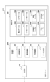
- FIG. 1 is a schematic diagram showing an example of the configuration of an article management system 1 according to one embodiment.
- the article management system 1 is a system for managing the usage of articles by users.
- any type of article may be used by the user, and the article may be inanimate (for example, machine, equipment, instrument, material, consumer goods, parts, vehicle or robot) or living (for example, animal or plant).
- the space in which each user can be active is divided into multiple areas 10a to 10n.
- a user 20a and articles 30a and 30b are present in the area 10a.
- a user 20b exists in the area 10b. Users 20a and 20b can freely move between multiple areas 10a-10n.
- the article management system 1 utilizes wireless devices, also called tags, for the purpose of article management.
- the article management system 1 includes three types of tags.
- a first type of tag (first wireless device) is a location tag installed in each of the areas 10a-10n.
- a second type of tag (second wireless device) is an article tag attached to each article managed by the article management system 1 .
- a third type of tag (third wireless device) is a user tag carried by a user.
- location tags 40a to 40n are installed in areas 10a to 10n, respectively.
- the installation position of each of the position tags 40a-40n may be fixed or changeable.
- the position tag When the area itself moves (for example, the work site moves), the position tag may be moved along with the movement of the area.
- Article tags 50a and 50b are attached to the articles 30a and 30b, respectively. Each item tag moves as the corresponding item moves.
- the user 20a carries a user tag 60a.
- User 20b carries user tag 60b.
- the user tags 60a and 60b may be IC card-type devices such as employee ID cards or admission cards.
- the expression that the user carries some object broadly encompasses various modes in which the user moves with the object (for example, moves while holding or wearing the object). do.
- area 10 when it is not necessary to distinguish the areas 10a to 10n from each other, they are collectively referred to as area 10 by omitting the alphabet at the end of the code.
- articles 30 articles 30a, 30b
- location tags 40 40a-40n
- article tags 50 article tags 50a, 50b
- user tags 60 user tags 60a, 60b
- the number of users 20 and the number of items 30 existing in the item management system 1 are not limited to the example shown in FIG. 1, and may be any number.
- each of the tags such as the position tag 40, article tag 50, and user tag 60 is assumed to be a passive RFID (Radio Frequency Identification) tag (passive tag).
- a passive tag consists of a small IC (Integrated Circuit) chip with built-in memory and an antenna, and stores identification information and other information for identifying the tag in the memory.
- the identification information is simply referred to as an ID
- the identification information for identifying a tag is also referred to as a tag ID.
- the tag ID may be regarded as information that identifies the object to which the tag is attached.
- the IC chip of the passive tag operates using the energy of the electromagnetic wave emitted from the tag reader, modulates the tag ID and other information stored in the memory into an information signal, and transmits the information signal from the antenna. (return).
- item tags 50a and 50b have unique tag IDs 51a and 51b, respectively, embedded within the tags.
- the tag ID 51 of each article tag 50 is associated with the article 30 to which the article tag 50 is attached in a database described later.
- Each user tag 60 also has a unique tag ID embedded within the tag.
- the tag ID of each user tag 60 is associated with the user 20 carrying that user tag 60 .
- Each location tag 40 also has a unique tag ID embedded within the tag.
- the tag ID of each position tag 40 is associated with the area 10 in which the position tag 40 is installed.
- each tag may be an active RFID tag.
- a tag may be called a beacon tag if it actively (for example, periodically) transmits information to its surroundings using power from an internal battery.
- each tag may be a wireless device that returns information in response to a signal from the reader, eg, in Near Field Communication (NFC) or Bluetooth.
- NFC Near Field Communication
- Each tag may be called by any name such as an IC tag, an IC card, or a responder.
- the user 20a carries a tag reader 100a in addition to the user tag 60a.
- the user 20b carries a tag reader 100b in addition to the user tag 60b.
- each tag reader 100 can be carried by a user 20 to move between multiple areas 10a-10n.
- the article management system 1 includes at least one tag reader 100, a management server 200, and a terminal device 300 as described above. Note that each tag reader 100 need not be associated with a specific user 20 . For example, users 20 a and 20 b may exchange tag readers 100 a and 100 b with each other, or multiple users 20 may share a smaller number of tag readers 100 .
- Network 5 may be a wired network, a wireless network, or any combination thereof. Examples of network 5 may include the Internet, intranets and cloud networks.
- the tag reader 100 is a reader capable of reading information stored in a wireless device such as an RFID tag from the wireless device.
- the tag reader 100 can detect the article 30 by reading the tag ID 51 from the article tag 50 attached to the article 30 .
- the tag reader 100 performs reading periodically or in response to some trigger such as user operation, and transmits the tag reading result to the management server 200 .
- the tag reader 100 may communicate directly with the management server 200, or indirectly communicate with the management server 200 via some relay device (for example, a PC or smartphone carried by the user 20). good too.
- some relay device for example, a PC or smartphone carried by the user 20.
- the management server 200 is an information processing device that tracks the locations of the user 20 and the item 30 and records the usage of the item 30 by the user 20 in a database.
- the management server 200 may be implemented as an application server, database server, or cloud server using, for example, a high-performance general-purpose computer. An example of a specific configuration of the management server 200 will be further described later.
- management server 200 may be provided by a single device, or may be provided by a plurality of physically separate devices. It may be provided by cooperating. Also, in this embodiment, an example in which the management server 200 holds the database will be described, but a device separate from the management server 200 may hold part or all of the database. For example, some data may be held by the wireless device, tag reader 100 or terminal device 300 .
- the terminal device 300 is used by the user 20 or administrator of the article management system 1.
- the terminal device 300 may be, for example, a general-purpose terminal such as a PC (Personal Computer) or a smartphone, or may be a dedicated terminal specialized for the purpose of article management.
- the terminal device 300 may be portable or stationary.
- the terminal device 300 typically includes an input device that receives user input, a communication interface that communicates with other devices (for example, the management server 200), and a display device that displays information.
- the terminal device 300 is used when the user 20 registers a usage reservation for the article 30 with the management server 200 .
- the terminal device 300 is used when the administrator views usage record data, which can be provided from the management server 200 and will be described later.
- FIG. 1 depicts the tag reader 100 and the terminal device 300 as separate devices, an integrated device having the functions of both the tag reader 100 and the terminal device 300 may be provided.
- the terminal device 300 may be carried by the user 20 and relay communication between the tag reader 100 and the management server 200 .
- the functions of the management server 200 described in this embodiment may be implemented in the terminal device 300 .
- FIG. 2 is a block diagram showing an example of the configuration of the tag reader 100 according to one embodiment.
- the tag reader 100 includes a control section 111, a storage section 112, a communication section 113, a measurement section 114, a power supply 115, and a reading section .
- the control unit 111 consists of a memory that stores computer programs and one or more processors (eg, CPU or microcontroller) that execute computer programs.
- the control unit 111 controls all functions of the tag reader 100 described in this specification. For example, the control unit 111 causes the reading unit 116 to try to read an RFID tag within the tag reading range, and temporarily stores the read information and the reading time in the storage unit 112 as reading result data. In parallel with reading the RFID tag, the control unit 111 causes the measurement unit 114 to measure the position of the tag reader 100 and stores the measurement result in the storage unit 112 . Then, the control unit 111 sends the reading result data and the measurement result data stored in the storage unit 112 to the management server 200 via the communication unit 113 together with the reader identification information (also referred to as reader ID) that identifies the own device. Send.
- the reader identification information also referred to as reader ID
- the storage unit 112 may include any type of storage medium, such as a semiconductor memory such as ROM (Read Only Memory) or RAM (Random Access Memory), an optical disk, or a magnetic disk. In this embodiment, the storage unit 112 stores the reading result data, the measurement result data, and the reader ID of the tag reader 100 described above.
- ROM Read Only Memory
- RAM Random Access Memory
- the storage unit 112 stores the reading result data, the measurement result data, and the reader ID of the tag reader 100 described above.
- the communication unit 113 is a communication interface for the tag reader 100 to communicate with the management server 200.
- the communication unit 113 may be a WLAN interface that communicates with a WLAN (Wireless Local Area Network) access point, or a cellular communication interface that communicates with a cellular base station.
- the communication unit 113 may be a connection interface (for example, a Bluetooth (registered trademark) interface or a USB (Universal Serial Bus) interface) for connection with a relay device.
- the measurement unit 114 is a unit capable of measuring the position of the tag reader 100.
- the measurement unit 114 uses self-position estimation technology, also called PDR (Pedestrian Dead Reckoning), to measure the amount of relative movement of the tag reader 100 from a certain reference position, and control the measured amount of movement. Output to unit 111 .
- the reference position for measuring the relative movement amount may be, for example, the position of the tag reader 100 when the tag reader 100 is activated.
- a relative movement amount of the tag reader 100 can be treated as a relative position.
- the measurement unit 114 includes a triaxial acceleration sensor 114a, a gyro sensor 114b, and a geomagnetic sensor 114c.
- the triaxial acceleration sensor 114a measures the acceleration applied to the tag reader 100 in a device coordinate system unique to the tag reader 100 and outputs first sensor data.
- the gyro sensor 114b measures the angular velocity of the tag reader 100, that is, changes in the posture of the tag reader 100, and outputs second sensor data.
- the geomagnetic sensor 114c measures the azimuth of the tag reader 100 in real space and outputs third sensor data. Based on the sensor data from these sensors, the measurement unit 114 accumulates the acceleration while converting the direction of the acceleration of the tag reader 100 into the direction in the coordinate system of the real space, thereby measuring the relative movement amount of the tag reader 100. can do.
- the relative movement amount output from the measurement unit 114 to the control unit 111 may be a two-dimensional vector in the horizontal plane, or a three-dimensional vector including a component in the height direction.
- the position coordinates of the installation position of each position tag 40 are known and registered in the database. Therefore, the current absolute position (positional coordinates) of the tag reader 100 is determined based on the relative movement amount from the time when the tag reader 100 detects the positional tag 40 to the current time and the known positional coordinates of the positional tag 40. can be estimated.
- the management server 200 estimates the absolute position of the tag reader 100 will be mainly described. good too.
- the measurement unit 114 may measure the current geographical position of the tag reader 100 using GPS (Global Positioning System).
- the measurement unit 114 may perform base station positioning or wireless LAN positioning for estimating the current position using known position coordinates of a connected base station or wireless LAN access point.
- FIG. 2 shows an example in which the tag reader 100 includes the measurement unit 114
- the measurement unit 114 may be included in an external device capable of communicating with the tag reader 100 and carried by the user together with the tag reader 100. good.
- the tag reader 100 receives movement amount information indicating the relative movement amount measured by the measuring unit 114 from the external device.
- the power supply 115 includes a battery and a DC-DC converter, and supplies electric power to the control unit 111, the storage unit 112, the communication unit 113, the measurement unit 114, and the reading unit 116 of the tag reader 100 to operate the electronic circuits.
- the battery may be a primary battery or a rechargeable secondary battery.
- the tag reader 100 may have connection terminals for connecting the tag reader 100 to an external power source for charging the power source 115 .
- the reading unit 116 is a unit that can read the information stored in each of the tags such as the position tag 40, article tag 50, and user tag 60 described above.
- reader 116 includes RF controller 120 , power amplifier 121 , filter 122 , first coupler 123 , second coupler 124 , antenna 125 , power detector 126 and canceller 127 .
- the RF controller 120 outputs a transmission signal (for example, a signal modulated in the UHF band) from the TX terminal to the power amplifier 121 under the control of the control section 111 .
- the power amplifier 121 amplifies the transmission signal input from the RF controller 120 and outputs it to the filter 122 .
- the amplification factor of the transmission signal here may be variably controllable, and the higher the amplification factor, the higher the output intensity of the electromagnetic waves radiated from the tag reader 100 .
- the filter 122 may be a low-pass filter, for example, and removes unnecessary low-frequency components of the transmission signal amplified by the power amplifier 121 .
- the first coupler 123 distributes the transmission signal that has passed through the filter 122 to the coupler 124 and the power detector 126 .
- the second coupler 124 outputs the transmission signal input from the first coupler 123 to the antenna 125 and outputs the reception signal input from the antenna 125 to the RF controller 120 .
- Antenna 125 transmits the transmission signal input from coupler 124 into the air as electromagnetic waves.
- the antenna 125 receives a signal returned from an RFID tag existing within the reading range of the tag reader 100 as a response to the transmitted signal, and outputs the received signal to the coupler 124 .
- antenna 125 may be an omni-directional antenna.
- antenna 125 may be a directional antenna with variably controllable beam direction.
- Power detection section 126 detects the power level of the signal input from first coupler 123 and outputs signal RF_DETECT indicating the detected power level to control section 111 .
- Canceller 127 receives signal CARRIER_CANCEL indicating the power level of the carrier wave from control unit 111 .
- the canceller 127 extracts the desired signal component of the received signal to be output to the RX terminal of the RF controller 120 by canceling the carrier wave component of the transmission signal based on CARRIER_CANCEL.
- the RF controller 120 demodulates the signal input from the RX terminal, acquires the tag ID and other information returned from the RFID tag, and outputs the acquired information to the control unit 111 . Further, RF controller 120 measures the reception level (also referred to as reception strength) of the signal input from the RX terminal and outputs the measurement result to control section 111 .
- reading unit 116 may attempt to read tags periodically (eg, once every second) without requiring explicit instructions from the user.
- the transmission of data from the communication unit 113 to the management server 200 can also be performed periodically (for example, once every few seconds) or each time the tag is read without requiring an explicit instruction by the user.
- the control unit 111 may exclude, from the data to be transmitted, records that are the same as the records that have been transmitted within the most recent predetermined period. .
- the control unit 111 determines that the RFID tag has been detected, and sends the read result data of the detected RFID tag to the management server. 200.
- one or both of the attempt to read the tag by the reading unit 116 and the transmission of data to the management server 200 are detected via an input device (e.g., button) provided on the tag reader 100. It may be performed according to a user operation.
- an input device e.g., button
- communication unit 113 indirectly communicates with management server 200 via a relay device, data transmission to management server 200 is performed only while the connection between communication unit 113 and the relay device is valid.
- FIG. 3 is a block diagram showing an example of the configuration of the management server 200 according to one embodiment.
- the management server 200 includes a communication section 210 , an article database (DB) 220 and a management section 230 .
- DB article database
- the communication unit 210 is a communication interface for the management server 200 to communicate with other devices.
- the communication unit 210 may be a wired communication interface or a wireless communication interface.
- the communication unit 210 communicates with the tag reader 100 and the terminal device 300 .
- the article DB 220 is a database that stores various information for tracking the positions of the user 20 and the article 30 and grasping the usage status of the article 30 .
- the article DB 220 includes an article table 310, an area table 320, a reader table 330, a user table 340, a reading result table 350, a history table 360, a reservation table 370, and a usage record table 380.
- the management unit 230 is a set of software modules that provide management functions for managing data in the article DB 220 .
- the individual software modules may operate by one or more processors (not shown) of management server 200 executing computer programs stored in memory (not shown).
- the management section 230 includes a position estimation section 231 , a history acquisition section 232 , a reservation management section 233 and a data generation section 234 .
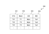
- Configuration of master data> 4A and 4B respectively show examples of configurations of the article table 310 and the area table 320 of the article DB 220.
- the item table 310 has four data items: tag ID 311, item ID 312, name 313, and type 314.
- the tag ID 311 is identification information that uniquely identifies the article tag 50 attached to each article 30 under the control of the system.
- the value of the tag ID 311 is the same as the tag ID value internally stored in the corresponding article tag 50 .
- the article ID 312 is identification information that uniquely identifies each article 30 .
- the name 313 represents the name of each item 30 .
- the items identified by the item IDs "IT01", “IT02” and “IT03” are given the names “item A", “item B" and “item C", respectively.
- article A" may correspond to the article 30a shown in FIG.
- Type 314 represents the type into which each item 30 is classified.
- the type of "goods A” and “goods C” is "Type 1”
- the type of "goods B” is "Type 2”.
- the values of the name 313 and type 314 of each item 30 may be determined by the user and registered in advance via a user interface (UI) provided by the management unit 230 .
- the values of name 313 and type 314 may be stored as item-related information on item tag 50 and read by tag reader 100 .
- the management server 200 receives the values of the name 313 and type 314 of the article 30 from the tag reader 100 and registers them in the article table 310 in response to the initial tag reading from the article tag 50 of each article 30 . can.
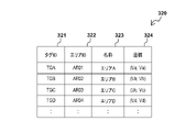
- the area table 320 has four data items: tag ID 321, area ID 322, name 323, and coordinates 324.
- the tag ID 321 is identification information that uniquely identifies the position tag 40 installed in each of the multiple areas 10 .
- the value of the tag ID 321 is the same as the tag ID value internally stored in the corresponding position tag 40 .
- the area ID 322 is identification information that uniquely identifies each area 10 .
- a name 323 represents the name of each area 10 .
- the areas identified by the area IDs "AR01”, “AR02”, “AR03” and “AR04" are respectively "area A", "area B", "area C” and "area D". is given the name.
- These names may actually be, for example, "construction section X", "floor Y", or "warehouse Z”.
- Coordinates 324 represent the position coordinates of the installation position of the position tag 40 installed in each area 10 .
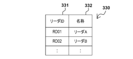
- 5A and 5B show examples of configurations of the reader table 330 and the user table 340, respectively.
- the reader table 330 has two data items, a reader ID 331 and a name 332.
- the reader ID 331 is identification information that uniquely identifies each tag reader 100 used in the system.
- Name 332 represents the name of each tag reader.
- the tag readers 100 identified by the reader IDs "RD01” and “RD02” are given the names “reader A” and “reader B", respectively.
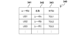
- the user table 340 has three data items: user ID 341, name 342, and tag ID 343.
- the user ID 341 is identification information that uniquely identifies each user 20 who uses the item 30 in the item management system 1 .
- Name 342 represents the name of each user. In the example of FIG. 5B, the name of the user 20 identified by the user ID "U001" is "user A”, the name of the user 20 identified by the user ID "U002" is “user B”, and the user ID "U003". The name of the identified user 20 is "user C”.
- the tag ID 343 is identification information that uniquely identifies the user tag 60 carried by each user 20 . The value of the tag ID 343 is the same as the tag ID value stored internally by the corresponding user tag 60 .
- user table 340 may have additional data items that hold authentication information (e.g., passwords or biometrics) for user authentication when logging into the system. .
- the reading result table 350 is a table for storing records of reading result data received from the tag reader 100 (hereinafter referred to as reading result records).
- FIG. 5C shows an example of the configuration of the reading result table 350.
- the reading result table 350 has four data items: reading time 351 , tag ID 352 , reader ID 353 and coordinates 354 .
- the read time 351 represents the time when the tag ID was read for each read result record.
- Tag ID 352 represents the tag ID read for each read result record.
- the reader ID 353 is identification information that identifies the tag reader 100 that has read the tag for each read result record. In the example of FIG.
- the first record of the reading result table 350 indicates that the tag reader 100a identified by the reader ID "RD01” reads the tag ID "TGA” (for example, the tag ID of the position tag 40a) at time "T01". is read.
- the second record indicates that the tag reader 100a read the tag ID "TGU1" (for example, the tag ID of the user tag 60a of the user 20a) at time "T02”.
- the third record indicates that tag reader 100a read tag ID "TG01" (for example, tag ID of article tag 50a of article 30a) at time "T03".
- Coordinates 354 represent the location coordinates of the point where the tag reader 100 was at the time the tag was read.
- the position estimating unit 231 determines that the user 20 associated with the read tag ID was present at the reading time indicated by the reading result data. Estimate location. User position estimation is performed using measurement result data periodically received from the tag reader 100 . For example, it is assumed that the tag reader 100a reads the tag ID of the position tag 40a at reading time T01 (first time point) and then reads the tag ID of the user tag 60a at reading time T02 (second time point).
- the amount of relative movement of the tag reader 100a from the reading time T01 to the reading time T02 corresponds to the difference in the amount of movement measured by the tag reader 100a at two points in time, and the position estimator 231 calculates this difference based on the measurement result data.
- the coordinates of the installation position of the position tag 40a installed in the area 10a are known and defined in the area table 320.
- FIG. Therefore, the position estimator 231 adds the relative movement amount of the tag reader 100a from the reading time T01 to the reading time T02 to the known position coordinates of the position tag 40a.
- Position can be estimated.
- the position estimation unit 231 additionally writes the position coordinates of each user 20 estimated in this way in the column of the coordinates 354 of the corresponding record of the reading result table 350 .
- the position estimating section 231 determines that the article 30 associated with the read tag ID exists at the reading time indicated by the reading result data. Estimate the position where the Item location estimation is also performed using measurement data received periodically from the tag reader 100 . For example, after the tag reader 100a reads the tag ID of the position tag 40a at reading time T01 (first time), it reads the tag ID of the article tag 50a attached to the article 30a at reading time T03 (third time).
- the relative movement amount of the tag reader 100a from the reading time T01 to the reading time T03 corresponds to the difference between the movement amounts measured by the tag reader 100a at two points in time, and the position estimator 231 calculates this difference based on the measurement result data. can be derived. Then, the position estimating unit 231 adds the relative movement amount of the tag reader 100a from the reading time T01 to the reading time T03 to the known position coordinates of the position tag 40a, thereby determining whether the article 30a existed at the reading time T03. Position can be estimated. The position estimation unit 231 additionally writes the position coordinates of each article 30 estimated in this way in the column of the coordinates 354 of the corresponding record in the reading result table 350 .
- the history acquisition unit 232 periodically acquires the history of the position of each article 30 and the history of movement of each user 20 from the reading result table 350 .
- the history acquisition unit 232 executes a process for acquiring the position history of each article 30 and the movement history of each user 20 each time a predefined period elapses, and obtains the acquired position history and movement history.
- the predefined time period may have any length, for example several hours, half a day or a day.
- the history acquisition unit 232 acquires the position history of the article 30 to which the article tag 50 is attached based on the result of reading the tag IDs from the position tag 40 and the article tag 50 by the tag reader 100. . Also, the history acquisition unit 232 acquires the movement history of the user 20 carrying the user tag 60 based on the result of reading the tag ID from the position tag 40 and the user tag 60 by the tag reader 100 .
- the position history of each article 30 is data indicating in which area 10 each article 30 was located in chronological order.
- the movement history of each user 20 is data indicating in which area each user 20 was located in chronological order.
- FIG. 6 is an explanatory diagram for explaining acquisition of position history and movement history by the history acquisition unit 232.
- FIG. The upper part of FIG. 6 shows only a part of exemplary contents of the reading result table 350 .
- the tag ID "TGU1" was read from the user tag 60a of the user 20a, and it is estimated that the user 20a was located at the position coordinates (U11, V11) at that time. shall have been Also, at 8:02 am on the same day, the tag ID "TG01" was read from the article tag 50a of the article 30a, and it was estimated that the article 30a was located at the position coordinates (U12, V12) at that time. do.
- the history table 360 has three data items: object 361 , time 362 and area 363 .
- the target 361 indicates the article ID of the article 30 or the user ID of the user 20 associated with each history record (hereinafter referred to as history record).
- the time 362 represents the representative time (for example, the start time) of each section (for example, having a time length of several minutes, several tens of minutes, or one hour) obtained by dividing the above-described period into shorter sections.
- the area 363 indicates in which area 10 the article 30 or the user 20 identified by the value of the target 361 existed in the corresponding section by the area ID or name of the area 10 .
- the history acquisition unit 232 extracts from the reading result table 350 the reading result record for the article 30a indicating the reading time belonging to a certain section. If there is no corresponding read result record, the history acquisition unit 232 may determine that the position of the article 30a in that section is unknown, and generate a history record with the area 363 blank. When one or more applicable reading result records are extracted, the history acquisition unit 232 determines, for example, which area 10 the position coordinates indicated by those reading result records belong to. Then, the history acquisition unit 232 can determine, for example, the area 10 corresponding to the largest number of read result records as the area 10 in which the article 30a existed in that section. In the example of FIG.
- the coordinates (U12, V12) of the estimated position of the article 30a at 8:02 a.m. belong to area A. It is determined that the article 30a (article A) existed in area A at . Further, since the coordinates (U11, V11) of the estimated position of the user 20a at 8:01 am belong to the area A, the user 20a It is determined that (user A) was in area A.
- the determination of which area 10 a certain position coordinate belongs to may be made based on, for example, the distance between the position coordinate and the known coordinates of the position tag 40 of each area 10 . As an example, if the position tag 40a among the plurality of position tags 40 is closest to the position coordinates (U12, V12), then the position coordinates (U12, V12) are said to belong to the area 10a associated with the position tag 40a. can be determined. As another example, the radius of each area 10 is predefined in the area table 320, and if the position coordinates fall within the circle defined by the position coordinates of the position tag 40 and the radius of the area 10, the position coordinates 10 may be determined.
- information representing the boundary of each area 10 may be defined in advance in the area table 320 .
- the position coordinates fall inside the boundary of the defined area 10, the position coordinates can be determined to belong to the area 10 in question.
- the determination of which area 10 the user 20 or the article 30 was located may be made without relying on the position coordinates of those objects.
- a position tag 40 is installed at the gate of each area 10 and the tag ID of the position tag 40 is always read by the tag reader 100 carried by the user 20 when entering/exiting each area 10 .
- the history acquisition unit 232 can determine the area 10 in which the user 20 or the article 30 existed from the detection history of the position tag 40 (for example, the time from entering to exiting the area 10 where the target is located). while the target is in its area 10).
- the reservation management unit 233 manages reservation data indicating reservations for use of the goods 30 in the reservation table 370 of the goods DB 220 .
- the reservation management unit 233 provides a UI for accepting reservation registration (for example, a reservation registration screen) to the user 20 or the administrator via the terminal device 300, and the reservation data input via the provided UI. may be registered in the reservation table 370.
- the reservation management unit 233 may provide the user 20 or the administrator via the terminal device 300 with a UI that enables browsing, correction, or deletion of registered reservation data.
- FIG. 7A shows an example of the configuration of the reservation table 370 of the article DB 220.
- the reservation table 370 has four data items: reservation ID 371 , period 372 , target item 373 and reservation person 374 .
- the reservation ID 371 is identification information that uniquely identifies each record of the reservation table 370 (hereinafter referred to as a reservation record).
- the period 372 indicates which period each reservation record covers.
- the target item 373 indicates which item 30 is targeted by each reservation record by the item ID of the item 30 .
- the reservation person 374 indicates the user 20 who is scheduled to use the item 30 represented by the target item 373 during the period represented by the period 372 by the user ID of the user 20 .
- a UI that enables such registration, viewing, correction, or deletion of reservation data may be configured by any method known to those skilled in the art, and therefore description thereof is omitted here.
- the data generator 234 associates the item 30 with the user 20 who used the item 30 based on a comparison between the location history of the item 30 and the movement history of one or more users 20 stored in the history table 360. Generate usage data. For example, the data generation unit 234 generates usage record data for each article 30 for the elapsed period each time a predefined period elapses, and stores the generated usage record data in the usage record table 380 .
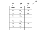
- FIG. 7B shows an example of the configuration of the usage record table 380 of the article DB 220. As shown in FIG.
- the usage record table 380 has three data items: target item 381 , period 382 and user 383 .
- Each record of the usage record table 380 indicates which user 20 used each item 30 in each period by combining the values of the target item 381 , period 382 and user 383 .
- the data generator 234 may allow the user 20 or the administrator to view the generated usage record data via the terminal device 300, for example.
- the data generation unit 234 may output usage record data for a specific period to a data file and transmit it to another device.
- the data generation unit 234 determines that the user 20 having the highest correlation with the position history of each article 30 (hereinafter referred to as the target article) in a certain period (hereinafter referred to as the target period) is the user 20 during the target period. can be determined to be the user who used the target item in. For example, for each user, the data generation unit 234 determines the matching degree of the time-based area where the user existed during the target period with respect to the time-based area where the target article existed during the target period. Then, the data generation unit 234 determines the users who used the target article during the target period based on the degree of matching determined for each user. At this time, the higher the determined degree of matching, the higher the correlation between the location history and the movement history can be evaluated. Therefore, in principle, it is determined that the user exhibiting the highest matching degree of history is the user who used the target product during the target period.
- the data generation unit 234 may further determine the degree of discrepancy between the time-based area where the user was present during the target period and the time-based area where the target article was present during the target period. Then, the data generation unit 234 may determine that a user whose determined degree of disagreement exceeds the reference value is not a user who used the target product during the target period, regardless of the degree of match in the history. That is, the correlation between location history and movement history may be rated lower the higher the discrepancy that is determined.
- the reference value to be compared with the non-matching degree may be, for example, a predefined fixed value or a product of the matching degree multiplied by a certain coefficient ⁇ (0 ⁇ 1).
- FIG. 8 is an explanatory diagram for explaining the determination of the usage history based on the history comparison according to the first embodiment.
- the target article is article A.
- the target period from 8:00 a.m. to noon on a certain date is divided into a total of eight sections, and the start times of these sections are shown in the second column from the left in FIG. 8 (hereinafter referred to as the time column).
- the time column there is To the left of the time column, the location history of item A that can be obtained from the history table 360 is shown. , 7th and 8th intervals.
- To the right of the time column movement histories of user A, user B, and user C that can be acquired from the history table 360 are shown.
- the data generation unit 234 identifies one or more users whose movement history includes the area included in the position history of the target article, and makes these users the targets of history comparison.
- the number of areas included in the location history is large (three areas A, B, and C in the example of FIG. 8)
- only a predetermined number of areas in descending order of the number of appearances in the location history are selected from the candidate users. May be used for primary filtering.
- the movement history of user C does not include any area described in the position history of article A, user C is excluded from history comparison targets.
- the number of article detections is the number of times the target article has been detected by the tag reader 100 (the number of times per section).
- the number of times of article detection is six.
- the number of matches is the number of sections in which the area matches between the position history of the target article and the movement history of each candidate user.
- User A is detected in the same area as the target article in five sections indicated by black circles in the figure, so the number of matches for user A is five.
- User B is detected in the same area as the target article in three sections indicated by black circles in the figure, so the number of matches for user B is three.
- the number of discrepancies is the number of sections in which the areas do not match between the position history of the target article and the movement history of each candidate user. It should be noted that sections in which at least one of the areas of the position history and movement history is blank may be ignored in the totalization. As for user A, since there is no section in which the areas do not match, the number of mismatches for user A is zero. User B is detected in an area different from the target article in the two sections indicated by X marks in the figure, so the number of discrepancies for user B is two.
- the data generation unit 234 may generate usage record data further based on the reservation data held in the reservation table 370 .
- Considering reservation data in determining usage history can reduce computational load by avoiding cross-comparison of multiple histories, or reduce accuracy when there are multiple users 20 exhibiting similar correlations. can make high-level decisions.
- the data generation unit 234 first generates the specified item 30 for the location history of the item 30 of users 20 may be compared. Then, when the correlation between these histories satisfies a predetermined criterion, it is determined that the specific user 20 used the item 30 during the target period without considering the movement histories of other users 20. good too.
- the predetermined criterion here may include that the degree of matching between the histories described above exceeds a certain reference value, and may further include that the degree of non-matching between the histories does not exceed another reference value.
- the user 20 registered as the user of the item 30 has a high probability of actually using the item 30 according to the reservation.
- Such an approach thus makes it possible in many cases to avoid the primary filtering of candidate users and the computation and inter-comparison of statistics for multiple users 20 . If the correlation between the movement history of the user 20 who is the reservation person and the location history of the target item does not satisfy the criteria, the remaining users 20 are temporarily filtered, and statistical values for the candidate users are calculated and compared with each other. , the user 20 who used the target item may be determined.
- FIG. 9 is an explanatory diagram for explaining the determination of the usage record based on the history comparison according to the second embodiment.
- the target article is article C.
- a target period (YMD_1) from 8:00 am to 12:00 noon on a certain date is divided into a total of eight sections, and the start times of these sections are indicated in the time column.
- the position history of article C is shown on the left of the time column, and the movement history of user D, user E, and user A is shown on the right of the time column.
- FIG. 9 partially shows the reservation data registered in the reservation table, and this reservation data indicates that the user D was scheduled to use the article C during the target period. Therefore, the data generator 234 first compares the movement history of the user D who made the reservation with the position history of the article C.
- the data generation unit 234 determines that one of the candidate users was the person who reserved the target item. may preferentially determine that the user indicated by the reservation data has used the target article. Since it is highly probable that the user 20 registered as the user of the item 30 will actually use the item 30 according to the reservation, such a method can determine with high accuracy the actual use record that matches the fact. .
- FIG. 10 is an explanatory diagram for explaining the determination of the usage history based on the history comparison according to the third embodiment.
- the target article is article A.
- a target period (YMD_2) from 13:00 to 17:00 on a certain date is divided into a total of eight sections, and the start times of these sections are indicated in the time column.
- the position history of the article A is shown on the left side of the time column, and the movement histories of the users A, B, and C are shown on the right side of the time column.
- the data generation unit 234 identifies one or more users whose movement history includes the area included in the position history of the target article, and makes these users the targets of history comparison.
- reservation data already registered in the reservation table is partially shown, and this reservation data indicates that user B was scheduled to use item A during the target period. Therefore, the data generation unit 234 can determine that the user B used the item A during the target period based on the correlation between histories and the usage reservation during the target period.
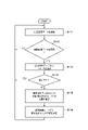
- FIG. 11 is a flowchart showing an example of the flow of position estimation processing mainly performed by the position estimation unit 231 of the management server 200. As shown in FIG. The position estimation process of FIG. 11 can be repeatedly executed while at least one tag reader 100 is operating in the article management system 1.
- FIG. 11 is a flowchart showing an example of the flow of position estimation processing mainly performed by the position estimation unit 231 of the management server 200. As shown in FIG. The position estimation process of FIG. 11 can be repeatedly executed while at least one tag reader 100 is operating in the article management system 1.
- FIG. 11 is a flowchart showing an example of the flow of position estimation processing mainly performed by the position estimation unit 231 of the management server 200. As shown in FIG. The position estimation process of FIG. 11 can be repeatedly executed while at least one tag reader 100 is operating in the article management system 1.
- FIG. 11 is a flowchart showing an example of the flow of position estimation processing mainly performed by the position estimation unit 231 of the management server 200. As shown in FIG. The position estimation process of FIG.
- the position estimation unit 231 receives measurement result data transmitted from the tag reader 100 via the communication unit 210 .
- the position estimation unit 231 waits for reception of reading result data from the tag reader 100 in parallel with reception of measurement result data. If read result data has been received from the tag reader 100, the process proceeds to S113. If the read result data is not received, the process returns to S111.
- the position estimation unit 231 adds a record corresponding to the read result data received from the tag reader 100 to the read result table 350 . Processing thereafter branches at S114 depending on whether the received read result data indicates that the tag ID of the position tag 40 has been read. If the tag ID of the position tag 40 has been read, the process returns to S111. If the tag ID of the article tag 50 or the user tag 60 is read instead of the position tag 40, the process proceeds to S115.
- the position estimating unit 231 calculates the position of the tag reader 100 at (or near) the reading time indicated by the received reading result data as the position of the tag reader 100 from when the same tag reader 100 detected the position tag 40. It is derived based on the amount of relative movement. The position derived here can be represented by the sum of the known position coordinates of the position tag 40 detected at a certain point in time and the amount of relative movement of the tag reader 100 from that point in time that can be calculated from the measurement result data. Then, the position estimation unit 231 estimates that the detected object (the article 30 attached with the article tag 50 or the user 20 carrying the user tag 60) is located at the derived position. Next, in S116, the position estimation unit 231 adds the position coordinates of the estimated position of the detected target to the column of coordinates 354 of the reading result record added to the reading result table 350 in S113. Then, the process returns to S111.
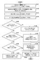
- FIG. 12 is a flowchart showing an example of the flow of history acquisition processing mainly executed by the history acquisition unit 232 of the management server 200. As shown in FIG. The history acquisition process in FIG. 12 can be executed for an elapsed period, for example, each time a period of several hours, half a day, or one day elapses.
- the history acquisition process consists of repetition (loop) of history acquisition for each section included in the target period.
- An interval treated in one iteration is referred to herein as a target interval.
- the history acquisition unit 232 extracts from the reading result table 350 the reading result record having the reading time belonging to the target section.
- the history acquisition unit 232 starts repetition (sub-loop) of history acquisition with each of the plurality of users 20 as the target user.
- the history acquisition unit 232 further extracts a record indicating the tag ID of the user tag 60 of the target user from the reading result record acquired in S122.
- the history acquisition unit 232 determines the area 10 in which the target user was present in the target section based on the value of the position coordinates of the extracted reading result record (detection position of the user tag 60). For example, the history acquisition unit 232 may determine that the target user exists in the area 10 associated with the position tag 40 installed closest to the detection position of the user tag 60 .
- the history acquisition unit 232 if the detection position of the user tag 60 falls within a certain area 10 determined by the definition of a simple area radius or the definition of a boundary having a more complicated shape, the target user existed in the area 10.
- the history acquisition unit 232 may determine the area 10 where the target user was present based on the values of the position coordinates of the reading result records by majority voting. good.
- the history acquisition unit 232 adds to the history table 360 a history record including the user ID of the target user, the time representing the target section, and the area ID or name of the area 10 determined in S ⁇ b>125 . If it is determined that acquisition of such movement histories has been completed for all target users (S127), the process proceeds to S130.
- the history acquisition unit 232 starts repetition (sub-loop) of history acquisition with each of the plurality of articles 30 as the target article.
- the history acquisition unit 232 further extracts a record indicating the tag ID of the article tag 50 of the target article from the read result record acquired in S122.
- the history acquisition unit 232 determines the area 10 in which the target article was present in the target section based on the value of the position coordinates of the extracted reading result record (the detection position of the article tag 50).
- the area determination method here may be the same as the method described in relation to S125.
- the history acquisition unit 232 adds to the history table 360 a history record including the item ID of the target item, the time representing the target section, and the area ID or name of the area 10 determined in S ⁇ b>132 .
- the process proceeds to S136.
- the history acquisition unit 232 determines whether there are unprocessed sections remaining in the target period, and if there are unprocessed sections remaining, the processing steps of S122 to S134 are executed for the next section. When it is determined that the acquisition of histories for all sections has been completed, the history acquisition process of FIG. 12 ends.
- FIGS. 13 and 14 are flowcharts showing an example of the flow of usage record generation processing mainly executed by the data generation unit 234 of the management server 200.
- FIG. For example, similar to the history acquisition process described above, the usage record generation process can be periodically executed each time the target period elapses. Although the usage history generation process can be repeated for each item 30 under the control of the system, FIGS. 13 and 14 only show the flow of processing for a single target item for the sake of clarity of explanation. .
- the data generation unit 234 determines the degree of match and the degree of mismatch between the position history of the target item and the movement history of each of the candidate users identified in S141.
- the data generation unit 234 selects candidate users whose degree of matching determined in S142 exceeds the first reference value.
- the data generation unit 234 excludes candidate users whose degree of disagreement determined in S142 exceeds a second reference value (lower than the first reference value) from the candidate users selected in S143.
- the data generator 234 determines whether at least one selected candidate user remains. If there are no selected candidate users remaining, the process proceeds to S146. On the other hand, if at least one selected candidate user remains, the process proceeds to S147.
- the data generation unit 234 determines that no user 20 used the target product during the target period. Then, the process proceeds to S152.
- the data generation unit 234 determines whether there are multiple candidate users with the highest degree of matching among the remaining candidate users. If there is only one candidate user with the highest degree of matching, the process proceeds to S148. On the other hand, if there are multiple candidate users with the highest degree of matching, the process proceeds to S149.
- the data generation unit 234 determines that the candidate user with the highest degree of matching used the target product during the target period. Then, the process proceeds to S152.
- the data generation unit 234 refers to the reservation data for the target item during the target period, and determines whether the remaining candidate users include the person who planned to use the target item. If the remaining candidate users do not include the reservation person, the process proceeds to S150. On the other hand, if the remaining candidate users include the reservation person, the process proceeds to S151.
- the data generation unit 234 determines the user 20 who has used the target item among the remaining candidate users according to some other conditions. For example, the data generator 234 may determine that all of the remaining candidate users "may" have used the target product during the target period. Then, the process proceeds to S152.
- the data generation unit 234 determines that the reservation person who was planning to use the target item actually used the target item during the target period. Then, the process proceeds to S152.
- the data generation unit 234 generates a record of the usage history of the target article for the target period according to the determination at S146, S148, S150 or S151, and adds the generated record to the usage history table 380.
- the data generation unit 234 determines whether there is a reservation for using the target article during the target period by referring to the reservation table 370. . If there is no usage reservation, the process proceeds to S165. If there is a reservation for use, the process proceeds to S161.
- the data generation unit 234 identifies the reservation person indicated by the reservation record of the reservation table 370 as the first candidate user whose history comparison should be preferentially performed.
- the data generator 234 determines the degree of matching and the degree of mismatching between the position history of the target article and the movement history of the first candidate user.
- the data generation unit 234 determines whether or not the correlation between the position history and the movement history, that is, the matching degree and the non-matching degree determined in S162 satisfy a certain criterion.
- the criterion here may be, for example, that the degree of matching exceeds the above-described first reference value and the degree of non-matching does not exceed the above-described second reference value. If the correlation between histories satisfies the criterion, the process proceeds to S164. On the other hand, if the correlation between histories does not satisfy the criterion, the process proceeds to S165.
- the data generation unit 234 determines that the first candidate user who made the reservation actually used the target item during the target period. Then, the process proceeds to S167.
- the data generation unit 234 performs primary filtering based on the position history of the target item for the users 20 other than the first candidate users, and identifies candidate users who have used the target item.
- the primary filtering here may be performed in the same manner as in S141 of FIG.
- the data generation unit 234 determines the correlation between the movement history of each of the candidate users identified in S165 and the position history of the target item, and determines the target item during the target period based on the determined correlation.
- the user 20 who used it is determined.
- the determination may be made in the same manner as in S142-S150 of FIG. 13, except that the first candidate user has already been excluded. Then, the process proceeds to S167.
- the data generation unit 234 generates a record of the usage history of the target article for the target period according to the determination at S164 or S166, and adds the generated record to the usage history table 380.
- the first wireless devices are installed in a plurality of areas, the second wireless devices are attached to articles, and the third wireless devices are carried by a plurality of users.
- At least one reader attempts to read identifying information from the wireless device.
- an article location history based on the reading results from the first and second wireless devices and a movement history of each user based on the reading results from the first and third wireless devices are acquired, and these histories are compared. Based on this, data is generated indicating who actually used the item.
- reservation data indicating reservations for use of goods is managed in the database, and usage record data indicating users who have actually used the goods is further generated based on the reservation data.
- a comparison may be preferentially made between the movement history of the person who reserved the item and the location history of the item, who planned to use the item for a certain period of time.
- the user who is the reservation person indicated by the reservation data is given priority as the user who used the item. may be determined.
- the ambiguity of the usage history can be resolved, and the usage history that matches the fact can be determined with high accuracy.
- the correlation between the location history of the item and the movement history of the user is determined by the time-based area where the item was present during the period. It can be represented by the matching degree of the area by time when the user was present. According to such a configuration, it is possible to objectively evaluate the correlation between the position history of the article and the movement history of the user using quantitative numerical values, and to accurately determine the usage record of the article.
- the above correlation between the location history of the item and the movement history of the user can be further expressed by the degree of discrepancy between the area by time where the item was present in a certain period and the area by time where the user was present in that period. . According to such a configuration, it is possible to eliminate the possibility of erroneously determining that a user who has left the area where the article was present and has moved to another area is the user who used the article.
- each of the at least one reader can be carried by the user and moved between multiple areas.
- various wireless devices in the system can be sequentially sensed along with the user's normal activities, and reading results can be collected. Therefore, no additional workload is imposed on the user for obtaining the position history of the article and the movement history of the user.
- At least one reading device can measure the amount of relative movement from the reference position. Also, the installation position of each of the first wireless devices is known. Then, the relative movement amount measured from the time when the identification information is read from the first wireless device to the time when the identification information is read from the second or third wireless device, and the known installation of the first wireless device. The location of the item or user is estimated based on the location. Which area the item or user was in can be determined based on this estimated location. According to such a configuration, even if the reading device does not always communicate with an external system such as a GPS satellite, the position of the article and the user can be estimated to a certain degree of precision from the data accumulated over time. This makes it easier to achieve both a reduction in device cost and power consumption and an accurate determination of usage history.
- each wireless device is an RFID tag
- the reader uses the energy of electromagnetic waves radiated into the reading range to read information returned from the RFID tag.
- the wireless device attached to each item and the wireless device carried by each user do not need to be equipped with a battery and a complicated transmitter/receiver. , the scheme described above can be incorporated at low cost.
- a program that implements one or more functions is supplied to a system or device via a network or a storage medium, and one or more processors in the computer of the system or device reads and executes the program.
- format is also feasible. It can also be implemented by a circuit (eg, an ASIC) that implements one or more functions.
Landscapes
- Engineering & Computer Science (AREA)
- Business, Economics & Management (AREA)
- Entrepreneurship & Innovation (AREA)
- General Physics & Mathematics (AREA)
- Strategic Management (AREA)
- Human Resources & Organizations (AREA)
- Physics & Mathematics (AREA)
- Economics (AREA)
- Game Theory and Decision Science (AREA)
- Educational Administration (AREA)
- Development Economics (AREA)
- Remote Sensing (AREA)
- Radar, Positioning & Navigation (AREA)
- Marketing (AREA)
- Operations Research (AREA)
- Quality & Reliability (AREA)
- Tourism & Hospitality (AREA)
- General Business, Economics & Management (AREA)
- Theoretical Computer Science (AREA)
- Position Fixing By Use Of Radio Waves (AREA)
- Management, Administration, Business Operations System, And Electronic Commerce (AREA)
Abstract
複数のエリアにそれぞれ設置される第1無線デバイスと、物品に付される第2無線デバイスと、複数のユーザによりそれぞれ携帯される第3無線デバイスと、無線デバイスから識別情報を読取り可能な少なくとも1つの読取装置と、前記第1無線デバイス及び前記第2無線デバイスからの識別情報の読取りの結果に基づく前記物品の位置の履歴、並びに、前記第1無線デバイス及び前記第3無線デバイスからの識別情報の読取りの結果に基づく各ユーザの移動の履歴を取得する履歴取得部と、前記物品の位置の履歴と1人以上のユーザの移動の履歴との比較に基づいて、前記物品と前記物品を利用したユーザとを関連付ける利用実績データを生成する生成部と、を含む物品管理システムが提供される。
Description
本開示は、物品管理システム、データ生成方法及び情報処理装置に関する。
一般に、工場や建設作業の現場では、多様な機器(例えば、車両又は機械など)が利用される。適正な作業計画を策定し、作業の進捗を管理し、及び作業の安全を確保するためには、利用実績、即ち誰がどの機器を利用したのかに関する情報を正確に把握することが重要である。従来、こうした情報を記録に残す目的で、例えば機器の利用に要する鍵の貸出し及び返却の際に、利用者名及び利用時刻等の情報を台帳に記入する業務が行われていた。しかし、手作業で台帳に情報を記入する手法では、例えば記載の不正確さ又は記入忘れに起因して、記録が事実と合わなくなる事態が発生することがあった。
特許文献1は、物品を保管する保管庫の解錠及び施錠のための鍵にICタグを搭載し、鍵の貸出し及び返却の際にICタグから読取られる情報に基づいて、鍵の貸出しの履歴を記録する技術を開示している。
しかしながら、特許文献1により開示された技術で記録される履歴は、ユーザがいつからいつまで鍵を所持していたかを示すのであって、鍵を用いて利用可能となる物品をいつ誰が利用したのかを示すのではない。こうした技術は、例えば一旦貸出された鍵が他のユーザに受渡されてもその事実を認識できないなど、物品の利用に関する正確な記録を残すという観点では不完全である。
本発明は、上述した点に鑑み、物品の利用に関する正確性の高い記録を残すための仕組みを実現しようとするものである。
ある観点によれば、複数のエリアにそれぞれ設置される第1無線デバイスと、物品に付される第2無線デバイスと、複数のユーザによりそれぞれ携帯される第3無線デバイスと、無線デバイスから当該無線デバイスに記憶されている識別情報を読取り可能な少なくとも1つの読取装置と、前記少なくとも1つの読取装置による前記第1無線デバイス及び前記第2無線デバイスからの識別情報の読取りの結果に基づく前記物品の位置の履歴、並びに、前記少なくとも1つの読取装置による前記第1無線デバイス及び前記第3無線デバイスからの識別情報の読取りの結果に基づく各ユーザの移動の履歴を取得する履歴取得部と、前記物品の位置の履歴と1人以上のユーザの移動の履歴との比較に基づいて、前記物品と前記物品を利用したユーザとを関連付ける利用実績データを生成する生成部と、を含む物品管理システムが提供される。対応する方法及び情報処理装置もまた提供される。
本発明によれば、物品の利用に関する正確性の高い記録を残すことが可能となる。
以下、添付図面を参照して実施形態を詳しく説明する。なお、以下の実施形態は特許請求の範囲に係る発明を限定するものではない。実施形態には複数の特徴が記載されているが、これらの複数の特徴の全てが発明に必須のものとは限らず、また、複数の特徴は任意に組み合わせられてもよい。さらに、添付図面においては、同一若しくは同様の構成に同一の参照番号を付し、重複した説明は省略する。
<1.システムの概要>
図1は、一実施形態に係る物品管理システム1の構成の一例を示す模式図である。ここでは、物品管理システム1は、ユーザによる物品の利用の状況を管理するためのシステムである。物品管理システム1において、いかなる種類の物品がユーザにより利用されてもよく、物品は無生物(例えば、機械、機器、器具、資材、消費財、部品、車両又はロボット)であっても生物(例えば、動物又は植物)であってもよい。
図1は、一実施形態に係る物品管理システム1の構成の一例を示す模式図である。ここでは、物品管理システム1は、ユーザによる物品の利用の状況を管理するためのシステムである。物品管理システム1において、いかなる種類の物品がユーザにより利用されてもよく、物品は無生物(例えば、機械、機器、器具、資材、消費財、部品、車両又はロボット)であっても生物(例えば、動物又は植物)であってもよい。
物品管理システム1において、各ユーザが活動し得る空間は、複数のエリア10a~10nに区画される。エリア10aには、ユーザ20a、並びに、物品30a及び30bが存在している。エリア10bには、ユーザ20bが存在している。ユーザ20a及び20bは、複数のエリア10a~10nの間を自在に移動し得る。
物品管理システム1は、物品管理の目的のために、タグとも呼ばれる無線デバイスを活用する。本実施形態では、物品管理システム1は、3種類のタグを含む。第1の種類のタグ(第1無線デバイス)は、エリア10a~10nの各々に設置される位置タグである。第2の種類のタグ(第2無線デバイス)は、物品管理システム1において管理される物品の各々に付される物品タグである。第3の種類のタグ(第3無線デバイス)は、ユーザにより携帯されるユーザタグである。
図1の例では、エリア10a~10nに、それぞれ位置タグ40a~40nが設置されている。位置タグ40a~40nの各々の設置位置は、固定的であってもよく、又は変更可能であってもよい。エリアそのものが移動する場合(例えば、作業現場の移動)には、エリアの移動に伴って位置タグも移設されてよい。物品30a及び30bには、それぞれ物品タグ50a及び50bが付されている。各物品タグは、対応する物品の移動に伴って移動する。ユーザ20aは、ユーザタグ60aを携帯する。ユーザ20bは、ユーザタグ60bを携帯する。ユーザタグ60a及び60bは、例えば社員証又は入館証のようなICカード型のデバイスであってもよい。なお、本明細書において、ユーザが何らかの対象を携帯するとの表現は、ユーザがその対象と共に移動する様々な態様(例えば、対象を保持し又は装着した状態で移動するなど)を広く包含するものとする。
以下の説明において、エリア10a~10nを相互に区別する必要のない場合には、符号の末尾のアルファベットを省略することにより、これらをエリア10と総称する。物品30(物品30a、30b)、位置タグ40(40a~40n)、物品タグ50(物品タグ50a、50b)、ユーザタグ60(ユーザタグ60a、60b)、並びに他の要素についても同様である。物品管理システム1において存在するユーザ20の人数及び物品30の数は、図1に示した例に限定されず、いかなる数であってもよい。
本実施形態において、位置タグ40、物品タグ50及びユーザタグ60といったタグの各々は、パッシブ型のRFID(Radio Frequency IDentification)タグ(パッシブタグ)であるものとする。パッシブタグは、メモリを内蔵する小型のIC(Integrated Circuit)チップ、及びアンテナで構成され、メモリ内に当該タグを識別する識別情報及びその他の情報を記憶する。本明細書では、識別情報を単にID、タグを識別する識別情報をタグIDともいう。なお、タグIDは、タグが付された対象を識別する情報であるとみなされてもよい。パッシブタグのICチップは、タグリーダから放射される電磁波のエネルギーを利用して動作し、メモリ内に記憶されているタグID及びその他の情報を情報信号へと変調して、情報信号をアンテナから送信(返送)する。
図1の例では、物品タグ50a及び50bは、タグ内に埋め込まれた固有のタグID51a及び51bをそれぞれ有する。各物品タグ50のタグID51は、後述するデータベースにおいて、当該物品タグ50が付された物品30に関連付けられる。各ユーザタグ60もまた、タグ内に埋め込まれた固有のタグIDを有する。各ユーザタグ60のタグIDは、当該ユーザタグ60を携帯するユーザ20に関連付けられる。各位置タグ40もまた、タグ内に埋め込まれた固有のタグIDを有する。各位置タグ40のタグIDは、当該位置タグ40が設置されたエリア10に関連付けられる。
なお、他の実施形態において、各タグは、アクティブ型のRFIDタグであってもよい。各タグが内蔵するバッテリからの電力を利用して能動的に(例えば、周期的に)情報を周囲へ送信する場合、当該タグはビーコンタグと呼ばれてもよい。また別の実施形態において、各タグは、リーダからの信号に応答して、例えばNFC(Near Field Communication)方式又はBluetooth(登録商標)方式で情報を返送する無線デバイスであってもよい。各タグは、ICタグ、ICカード又はレスポンダなど、いかなる名称で呼ばれてもよい。
ユーザ20aは、ユーザタグ60aに加えて、タグリーダ100aを携帯する。ユーザ20bは、ユーザタグ60bに加えて、タグリーダ100bを携帯する。本実施形態において、各タグリーダ100は、ユーザ20により携帯されて複数のエリア10a~10nの間で移動し得る。物品管理システム1は、このような少なくとも1つのタグリーダ100と、管理サーバ200と、端末装置300とを含む。なお、各タグリーダ100は、特定のユーザ20に関連付けられなくてよい。例えば、ユーザ20a及び20bがタグリーダ100a及び100bを互いに交換してもよく、複数のユーザ20がより少数のタグリーダ100を共用してもよい。
タグリーダ100、管理サーバ200及び端末装置300は、ネットワーク5へ接続される。ネットワーク5は、有線ネットワーク、無線ネットワーク、又はそれらの任意の組合せであってよい。ネットワーク5の例は、インターネット、イントラネット及びクラウドネットワークを含み得る。
タグリーダ100は、RFIDタグなどの無線デバイスから当該無線デバイスに記憶されている情報を読取可能な読取装置である。例えば、タグリーダ100は、物品30に付された物品タグ50からタグID51を読取ることにより、物品30を検知することができる。タグリーダ100は、周期的に又はユーザ操作などの何らかのトリガに応じて読取りを実行し、タグ読取結果を管理サーバ200へ送信する。タグリーダ100は、管理サーバ200と直接的に通信可能であってもよく、又は何らかの中継装置(例えば、ユーザ20が携帯するPC又はスマートフォン)を介して間接的に管理サーバ200と通信可能であってもよい。タグリーダ100の具体的な構成の一例について、後にさらに説明する。
管理サーバ200は、ユーザ20及び物品30の位置を追跡し、ユーザ20による物品30の利用の状況をデータベースに記録する情報処理装置である。管理サーバ200は、例えば、高性能な汎用コンピュータを用いて、アプリケーションサーバ、データベースサーバ又はクラウドサーバとして実装されてよい。管理サーバ200の具体的な構成の一例について、後にさらに説明する。
図1には単一の管理サーバ200を示しているが、後に詳しく説明する管理サーバ200の機能は、単一の装置により提供されてもよく、又は物理的に別個の複数の装置が相互に連携することにより提供されてもよい。また、本実施形態では、管理サーバ200がデータベースを保持する例を説明するが、管理サーバ200とは別個の装置がデータベースの一部又は全部を保持していてもよい。例えば、一部のデータは、無線デバイス、タグリーダ100又は端末装置300により保持されてもよい。
端末装置300は、物品管理システム1のユーザ20又は管理者により使用される。端末装置300は、例えば、PC(Personal Computer)若しくはスマートフォンといった汎用端末であってもよく、又は物品管理の目的に特化した専用端末であってもよい。端末装置300は、携帯型であっても据え置き型であってもよい。端末装置300は、典型的には、ユーザ入力を受け付ける入力デバイス、他の装置(例えば、管理サーバ200)と通信する通信インタフェース、及び情報を表示する表示デバイスを備える。一例として、端末装置300は、ユーザ20が管理サーバ200へ物品30の利用予約を登録する際に使用される。他の例として、端末装置300は、管理サーバ200から提供され得る後述する利用実績データを管理者が閲覧する際に使用される。
なお、図1ではタグリーダ100及び端末装置300を別個の装置として描いているが、タグリーダ100及び端末装置300の双方の機能を有する統合的な装置が提供されてもよい。また、端末装置300が、ユーザ20により携帯され、タグリーダ100と管理サーバ200との間の通信を中継してもよい。また、本実施形態において説明する管理サーバ200の機能が、端末装置300において実現されてもよい。
<2.タグリーダの構成例>
図2は、一実施形態に係るタグリーダ100の構成の一例を示すブロック図である。図2を参照すると、タグリーダ100は、制御部111、記憶部112、通信部113、測定部114、電源115、及び読取部116を備える。
図2は、一実施形態に係るタグリーダ100の構成の一例を示すブロック図である。図2を参照すると、タグリーダ100は、制御部111、記憶部112、通信部113、測定部114、電源115、及び読取部116を備える。
制御部111は、コンピュータプログラムを記憶するメモリ、及びコンピュータプログラムを実行する1つ以上のプロセッサ(例えば、CPU又はマイクロコントローラ)からなる。制御部111は、本明細書で説明するタグリーダ100の機能全般を制御する。例えば、制御部111は、読取部116にタグ読取レンジ内のRFIDタグの読取りを試行させ、読取られた情報及び読取時刻を、読取結果データとして記憶部112に一時的に記憶させる。また、制御部111は、RFIDタグの読取りと並行して、測定部114にタグリーダ100の位置を測定させ、その測定結果を記憶部112に記憶させる。そして、制御部111は、記憶部112に記憶されている読取結果データ及び測定結果データを、自装置を識別するリーダ識別情報(リーダIDともいう)と共に、通信部113を介して管理サーバ200へ送信する。
記憶部112は、例えば、ROM(Read Only Memory)若しくはRAM(Random Access Memory)などの半導体メモリ、光ディスク、又は磁気ディスクといった、任意の種類の記憶媒体を含んでよい。本実施形態において、記憶部112は、上述した読取結果データ、測定結果データ、及びタグリーダ100のリーダIDを記憶する。
通信部113は、タグリーダ100が管理サーバ200と通信するための通信インタフェースである。例えば、通信部113は、WLAN(Wireless Local Area Network)アクセスポイントと通信するWLANインタフェース、又はセルラー基地局と通信するセルラー通信インタフェースであってもよい。また、通信部113は、中継装置との接続用の接続インタフェース(例えば、Bluetooth(登録商標)インタフェース又はUSB(Universal Serial Bus)インタフェース)であってもよい。
測定部114は、タグリーダ100の位置を測定可能なユニットである。本実施形態において、測定部114は、PDR(Pedestrian Dead Reckoning)とも呼ばれる自己位置推定技術を用いて、ある基準位置からのタグリーダ100の相対的な移動量を測定して、測定した移動量を制御部111へ出力する。相対移動量の測定の基準位置は、例えば、タグリーダ100が起動された時点のタグリーダ100の位置であってよい。タグリーダ100の相対移動量は、相対位置として扱われ得る。例えば、測定部114は、3軸加速度センサ114a、ジャイロセンサ114b、及び地磁気センサ114cを含む。3軸加速度センサ114aは、タグリーダ100に固有のデバイス座標系でタグリーダ100に加わる加速度を測定して、第1のセンサデータを出力する。ジャイロセンサ114bは、タグリーダ100の角速度、即ちタグリーダ100の姿勢の変化を測定して、第2のセンサデータを出力する。地磁気センサ114cは、実空間におけるタグリーダ100の方位を測定して、第3のセンサデータを出力する。測定部114は、これらセンサからのセンサデータに基づいて、タグリーダ100の加速度の方向を実空間の座標系における方向に換算しながら加速度を累積することで、タグリーダ100の相対的な移動量を測定することができる。測定部114から制御部111へ出力される相対移動量は、水平面内の2次元ベクトルであってもよく、又は高さ方向の成分も含む3次元ベクトルであってもよい。
後に説明するように、本実施形態において、各位置タグ40の設置位置の位置座標は、既知であってデータベースに登録されている。したがって、タグリーダ100がある位置タグ40を検知した時点から現在時点までの相対移動量と、当該位置タグ40の既知の位置座標とに基づいて、タグリーダ100の現在の絶対位置(の位置座標)を推定することができる。本実施形態では、管理サーバ200がタグリーダ100の絶対位置を推定する例を主に説明するが、タグリーダ100の制御部111又は測定部114がデータベースへアクセスしてタグリーダ100の絶対位置を推定してもよい。他の実施形態において、測定部114は、GPS(Global Positioning System)を利用してタグリーダ100の現在の地理的位置を測定してもよい。また別の実施形態において、測定部114は、接続先の基地局又は無線LANアクセスポイントの既知の位置座標を利用して現在位置を推定する基地局測位又は無線LAN測位を行ってもよい。
なお、図2にはタグリーダ100が測定部114を含む例を示しているが、測定部114は、タグリーダ100と通信可能であってタグリーダ100と共にユーザにより携帯される外部デバイスに含まれていてもよい。その場合には、タグリーダ100は、外部デバイスから測定部114により測定された相対的な移動量を示す移動量情報を受信する。
電源115は、バッテリ及びDC-DCコンバータを含み、タグリーダ100の制御部111、記憶部112、通信部113、測定部114及び読取部116に電子回路を動作させるための電力を供給する。バッテリは、一次電池であってもよく、又は充電可能な二次電池であってもよい。図示していないものの、タグリーダ100は、電源115の充電のためにタグリーダ100を外部電源へ接続するための接続端子を有していてもよい。
読取部116は、上述した位置タグ40、物品タグ50及びユーザタグ60といったタグの各々から当該タグが記憶している情報を読取可能なユニットである。図2を参照すると、読取部116は、RFコントローラ120、パワーアンプ121、フィルタ122、第1カプラ123、第2カプラ124、アンテナ125、電力検知部126及びキャンセラ127を含む。RFコントローラ120は、制御部111による制御に従って、TX端子からパワーアンプ121へ送信信号(例えば、UHF帯で変調された信号)を出力する。パワーアンプ121は、RFコントローラ120から入力された送信信号を増幅して、フィルタ122へ出力する。ここでの送信信号の増幅率は可変的に制御可能であってもよく、増幅率がより高いほどタグリーダ100から放射される電磁波の出力強度は高められる。フィルタ122は、例えばローパスフィルタであってよく、パワーアンプ121による増幅後の送信信号の不要な低周波成分を除去する。第1カプラ123は、フィルタ122を通過した送信信号をカプラ124及び電力検知部126へ分配する。第2カプラ124は、第1カプラ123から入力される送信信号をアンテナ125へ出力し、及びアンテナ125から入力される受信信号をRFコントローラ120へ出力する。アンテナ125は、カプラ124から入力される送信信号を空中へ電磁波として送信する。また、アンテナ125は、送信信号への応答としてタグリーダ100の読取レンジ内に存在するRFIDタグから返送される信号を受信し、受信信号をカプラ124へ出力する。一例として、アンテナ125は、全方向アンテナであってもよい。他の例として、アンテナ125は、ビーム方向を可変的に制御可能な指向性アンテナであってもよい。電力検知部126は、第1カプラ123から入力される信号の電力レベルを検知し、検知した電力レベルを示す信号RF_DETECTを制御部111へ出力する。キャンセラ127は、搬送波の電力レベルを示す信号CARRIER_CANCELを制御部111から受け付ける。そして、キャンセラ127は、CARRIER_CANCELに基づき、送信信号の搬送波成分をキャンセルすることにより、RFコントローラ120のRX端子へ出力されるべき受信信号の所望の信号成分を抽出する。RFコントローラ120は、RX端子から入力される信号を復調して、RFIDタグから返送されたタグIDその他の情報を取得し、取得した情報を制御部111へ出力する。また、RFコントローラ120は、RX端子から入力される信号の受信レベル(受信強度ともいう)を測定し、測定結果を制御部111へ出力する。
本実施形態において、読取部116によるタグ読取りの試行は、ユーザによる明示的な指示を要することなく、(例えば、毎秒1回など)周期的に行われ得る。通信部113から管理サーバ200へのデータの送信もまた、ユーザによる明示的な指示を要することなく、(例えば、数秒ごとに1回など)周期的に、又はタグ読取りの都度行われ得る。制御部111は、冗長なデータの送信を省略して通信の負荷を削減するために、直近の所定の期間内に送信済みのレコードと同一のレコードを、送信されるデータから除外してもよい。制御部111は、RFIDタグからの受信信号の受信レベルが予め設定される最小検知レベルを上回る場合に、当該RFIDタグを検知したと判定して、検知したRFIDタグについての読取結果データを管理サーバ200へ送信してもよい。なお、他の実施形態において、読取部116によるタグ読取りの試行、及び管理サーバ200へのデータの送信の一方又は双方が、タグリーダ100に設けられる入力デバイス(例えば、ボタン)を介して検知されるユーザ操作に応じて行われてもよい。通信部113が中継装置を介して間接的に管理サーバ200と通信する場合、管理サーバ200へのデータの送信は、通信部113と中継装置との間の接続が有効である間にのみ行われてもよい。
<3.管理サーバの構成例>
<3-1.基本的な構成>
図3は、一実施形態に係る管理サーバ200の構成の一例を示すブロック図である。図3を参照すると、管理サーバ200は、通信部210、物品データベース(DB)220及び管理部230を備える。
<3-1.基本的な構成>
図3は、一実施形態に係る管理サーバ200の構成の一例を示すブロック図である。図3を参照すると、管理サーバ200は、通信部210、物品データベース(DB)220及び管理部230を備える。
通信部210は、管理サーバ200が他の装置と通信するための通信インタフェースである。通信部210は、有線通信インタフェースであってもよく、又は無線通信インタフェースであってもよい。本実施形態において、通信部210は、タグリーダ100及び端末装置300と通信する。物品DB220は、ユーザ20及び物品30の位置の追跡及び物品30の利用状況の把握のための多様な情報を記憶するデータベースである。本実施形態において、物品DB220は、物品テーブル310、エリアテーブル320、リーダテーブル330、ユーザテーブル340、読取結果テーブル350、履歴テーブル360、予約テーブル370及び利用実績テーブル380を含む。管理部230は、物品DB220内のデータを管理する管理機能を提供する、複数のソフトウェアモジュールの集合である。個々のソフトウェアモジュールは、管理サーバ200の1つ以上のプロセッサ(図示せず)がメモリ(図示せず)に記憶されるコンピュータプログラムを実行することにより動作し得る。本実施形態において、管理部230は、位置推定部231、履歴取得部232、予約管理部233及びデータ生成部234を含む。
<3-2.マスタデータの構成>
図4A及び図4Bは、物品DB220の物品テーブル310及びエリアテーブル320の構成の例をそれぞれ示している。
図4A及び図4Bは、物品DB220の物品テーブル310及びエリアテーブル320の構成の例をそれぞれ示している。
物品テーブル310は、タグID311、物品ID312、名称313及び種別314という4つのデータ項目を有する。タグID311は、システムの管理下の物品30の各々に付された物品タグ50を一意に識別する識別情報である。タグID311の値は、対応する物品タグ50が内部で記憶しているタグIDの値と同一である。物品ID312は、各物品30を一意に識別する識別情報である。名称313は、各物品30の名称を表す。図4Aの例では、物品ID「IT01」、「IT02」及び「IT03」で識別される物品に、それぞれ「物品A」、「物品B」及び「物品C」という名称が与えられている。ここでの「物品A」は図1に示した物品30aに、「物品B」は図1に示した物品30bに対応してよい。種別314は、各物品30が分類される種別を表す。図4Aの例では、「物品A」及び「物品C」の種別は「Type1」であり、「物品B」の種別は「Type2」である。各物品30の名称313及び種別314の値は、ユーザにより決定され、管理部230により提供されるユーザインタフェース(UI)を介して事前に登録されてもよい。その代わりに、名称313及び種別314の値は、物品タグ50に物品関連情報として記憶され、タグリーダ100により読取られてもよい。後者の場合、管理サーバ200は、各物品30の物品タグ50からの初回のタグ読取りに応じて、当該物品30の名称313及び種別314の値をタグリーダ100から受信して、物品テーブル310に登録し得る。
エリアテーブル320は、タグID321、エリアID322、名称323、及び座標324という4つのデータ項目を有する。タグID321は、複数のエリア10の各々に設置された位置タグ40を一意に識別する識別情報である。タグID321の値は、対応する位置タグ40が内部で記憶しているタグIDの値と同一である。エリアID322は、各エリア10を一意に識別する識別情報である。名称323は、各エリア10の名称を表す。図4Bの例では、エリアID「AR01」、「AR02」、「AR03」及び「AR04」で識別されるエリアに、それぞれ「エリアA」、「エリアB」、「エリアC」及び「エリアD」という名称が与えられている。これら名称は、実際には、例えば「工事区画X」、「フロアY」、又は「倉庫Z」といったものであってよい。座標324は、各エリア10に設置された位置タグ40の設置位置の位置座標を表す。
図5A及び図5Bは、リーダテーブル330及びユーザテーブル340の構成の例をそれぞれ示している。
リーダテーブル330は、リーダID331及び名称332という2つのデータ項目を有する。リーダID331は、システム内で利用されるタグリーダ100の各々を一意に識別する識別情報である。名称332は、各タグリーダの名称を表す。図5Aの例では、リーダID「RD01」及び「RD02」で識別されるタグリーダ100に、それぞれ「リーダA」及び「リーダB」という名称が与えられている。
ユーザテーブル340は、ユーザID341、名称342及びタグID343という3つのデータ項目を有する。ユーザID341は、物品管理システム1において物品30を利用するユーザ20の各々を一意に識別する識別情報である。名称342は、各ユーザの名称を表す。図5Bの例では、ユーザID「U001」で識別されるユーザ20の名称は「ユーザA」、ユーザID「U002」で識別されるユーザ20の名称は「ユーザB」、ユーザID「U003」で識別されるユーザ20の名称は「ユーザC」である。タグID343は、各ユーザ20により携帯されるユーザタグ60を一意に識別する識別情報である。タグID343の値は、対応するユーザタグ60が内部で記憶しているタグIDの値と同一である。図には示していないものの、ユーザテーブル340は、システムへのログインの際に行われるユーザ認証のための認証情報(例えば、パスワード又は生体情報)を保持するさらなるデータ項目を有していてもよい。
<3-3.位置の追跡>
読取結果テーブル350は、タグリーダ100から受信される読取結果データのレコード(以下、読取結果レコードという)を蓄積するためのテーブルである。図5Cは、読取結果テーブル350の構成の一例を示している。読取結果テーブル350は、読取時刻351、タグID352、リーダID353及び座標354という4つのデータ項目を有する。読取時刻351は、各読取結果レコードについてタグIDの読取りが行われた時刻を表す。タグID352は、各読取結果レコードについて読取られたタグIDを表す。リーダID353は、各読取結果レコードについてタグ読取りを行ったタグリーダ100を識別する識別情報である。図5Cの例では、読取結果テーブル350の1番目のレコードは、リーダID「RD01」で識別されるタグリーダ100aが、時刻「T01」にタグID「TGA」(例えば、位置タグ40aのタグID)を読取ったことを示している。2番目のレコードは、タグリーダ100aが、時刻「T02」にタグID「TGU1」(例えば、ユーザ20aのユーザタグ60aのタグID)を読取ったことを示している。3番目のレコードは、タグリーダ100aが、時刻「T03」にタグID「TG01」(例えば、物品30aの物品タグ50aのタグID)を読取ったことを示している。座標354は、タグ読取りが行われた時点でタグリーダ100が存在していた地点の位置座標を表す。
読取結果テーブル350は、タグリーダ100から受信される読取結果データのレコード(以下、読取結果レコードという)を蓄積するためのテーブルである。図5Cは、読取結果テーブル350の構成の一例を示している。読取結果テーブル350は、読取時刻351、タグID352、リーダID353及び座標354という4つのデータ項目を有する。読取時刻351は、各読取結果レコードについてタグIDの読取りが行われた時刻を表す。タグID352は、各読取結果レコードについて読取られたタグIDを表す。リーダID353は、各読取結果レコードについてタグ読取りを行ったタグリーダ100を識別する識別情報である。図5Cの例では、読取結果テーブル350の1番目のレコードは、リーダID「RD01」で識別されるタグリーダ100aが、時刻「T01」にタグID「TGA」(例えば、位置タグ40aのタグID)を読取ったことを示している。2番目のレコードは、タグリーダ100aが、時刻「T02」にタグID「TGU1」(例えば、ユーザ20aのユーザタグ60aのタグID)を読取ったことを示している。3番目のレコードは、タグリーダ100aが、時刻「T03」にタグID「TG01」(例えば、物品30aの物品タグ50aのタグID)を読取ったことを示している。座標354は、タグ読取りが行われた時点でタグリーダ100が存在していた地点の位置座標を表す。
位置推定部231は、タグリーダ100からユーザタグ60についての読取結果データが受信されると、読取結果データにより示される読取時刻において、読取られたタグIDに関連付けられているユーザ20が存在していた位置を推定する。ユーザ位置の推定は、タグリーダ100から周期的に受信される測定結果データを用いて行われる。例えば、タグリーダ100aが、読取時刻T01(第1時点)に位置タグ40aのタグIDを読取った後、読取時刻T02(第2時点)にユーザタグ60aのタグIDを読取ったものとする。読取時刻T01から読取時刻T02までのタグリーダ100aの相対移動量は、2つの時点においてタグリーダ100aにより測定された移動量の差に相当し、位置推定部231は、測定結果データに基づいてこの差を導出することができる。ここで、エリア10aに設置された位置タグ40aの設置位置の座標は既知であり、エリアテーブル320において定義されている。したがって、位置推定部231は、位置タグ40aの既知の位置座標に、読取時刻T01から読取時刻T02までのタグリーダ100aの相対移動量を加算することにより、読取時刻T02においてユーザ20aが存在していた位置を推定することができる。位置推定部231は、このように推定される各ユーザ20の位置座標を、読取結果テーブル350の対応するレコードの座標354の欄に追記する。
同様に、位置推定部231は、タグリーダ100から物品タグ50についての読取結果データが受信されると、読取結果データにより示される読取時刻において、読取られたタグIDに関連付けられている物品30が存在していた位置を推定する。物品位置の推定もまた、タグリーダ100から周期的に受信される測定結果データを用いて行われる。例えば、タグリーダ100aが、読取時刻T01(第1時点)に位置タグ40aのタグIDを読取った後、読取時刻T03(第3時点)に物品30aに付された物品タグ50aのタグIDを読取ったものとする。読取時刻T01から読取時刻T03までのタグリーダ100aの相対移動量は、2つの時点においてタグリーダ100aにより測定された移動量の差に相当し、位置推定部231は、測定結果データに基づいてこの差を導出することができる。そして、位置推定部231は、位置タグ40aの既知の位置座標に、読取時刻T01から読取時刻T03までのタグリーダ100aの相対移動量を加算することにより、読取時刻T03において物品30aが存在していた位置を推定することができる。位置推定部231は、このように推定される各物品30の位置座標を、読取結果テーブル350の対応するレコードの座標354の欄に追記する。
<3-4.履歴の取得>
履歴取得部232は、読取結果テーブル350から定期的に、各物品30の位置の履歴及び各ユーザ20の移動の履歴を取得する。例えば、履歴取得部232は、予め定義された期間が経過する都度、各物品30の位置の履歴及び各ユーザ20の移動の履歴を取得するための処理を実行して、取得した位置履歴及び移動履歴を履歴テーブル360に格納する。予め定義された期間は、例えば、数時間、半日又は1日など、いかなる長さを有していてもよい。
履歴取得部232は、読取結果テーブル350から定期的に、各物品30の位置の履歴及び各ユーザ20の移動の履歴を取得する。例えば、履歴取得部232は、予め定義された期間が経過する都度、各物品30の位置の履歴及び各ユーザ20の移動の履歴を取得するための処理を実行して、取得した位置履歴及び移動履歴を履歴テーブル360に格納する。予め定義された期間は、例えば、数時間、半日又は1日など、いかなる長さを有していてもよい。
より具体的には、履歴取得部232は、タグリーダ100による位置タグ40及び物品タグ50からのタグIDの読取りの結果に基づいて、当該物品タグ50が付された物品30の位置履歴を取得する。また、履歴取得部232は、タグリーダ100による位置タグ40及びユーザタグ60からのタグIDの読取りの結果に基づいて、当該ユーザタグ60を携帯するユーザ20の移動履歴を取得する。本実施形態において、各物品30の位置履歴は、各物品30がどのエリア10に存在したかを時系列で示すデータである。また、各ユーザ20の移動履歴は、各ユーザ20がどのエリアに存在したかを時系列で示すデータである。
図6は、履歴取得部232による位置履歴及び移動履歴の取得について説明するための説明図である。図6の上段には、読取結果テーブル350の例示的な内容が一部のみ示されている。例えば、2021年X月Y日の午前8時1分にユーザ20aのユーザタグ60aからタグID「TGU1」が読取られ、その時点でユーザ20aが位置座標(U11,V11)に位置していたと推定されたものとする。また、同じ日の午前8時2分に物品30aの物品タグ50aからタグID「TG01」が読取られ、その時点で物品30aが位置座標(U12,V12)に位置していたと推定されたものとする。
図6の下段には、履歴取得部232により履歴テーブル360に格納される、物品30a(物品A)の位置履歴、ユーザ20a(ユーザA)の移動履歴、及びユーザ20b(ユーザB)の移動履歴の例が示されている。図示したように、履歴テーブル360は、対象361、時刻362及びエリア363という3つのデータ項目を有する。対象361は、履歴の各レコード(以下、履歴レコードという)に関連付けられる物品30の物品ID又はユーザ20のユーザIDを示す。時刻362は、上述した期間をより短く区分けした区間(例えば、数分、数十分又は1時間の時間長を有する)の各々の代表時刻(例えば、開始時刻)を表す。エリア363は、対応する区間において対象361の値で識別される物品30又はユーザ20がどのエリア10に存在したかを、当該エリア10のエリアID又は名称で表す。
例えば、履歴取得部232は、ある区間に属する読取時刻を示す物品30aについての読取結果レコードを読取結果テーブル350から抽出する。該当する読取結果レコードが無ければ、履歴取得部232は、その区間の物品30aの位置は不明であると判定し、エリア363が空欄の履歴レコードを生成してよい。該当する1つ以上の読取結果レコードが抽出された場合、履歴取得部232は、例えばそれら読取結果レコードにより示される位置座標がそれぞれどのエリア10に属するかを判定する。そして、履歴取得部232は、例えば最も多くの読取結果レコードに対応するエリア10を、その区間において物品30aが存在していたエリア10であると判定し得る。図6の例では、午前8時2分の時点の物品30aの推定位置の座標(U12,V12)がエリアAに属することから、左下に示したように、8時から8時半までの区間に物品30a(物品A)がエリアAに存在したと判定されている。また、午前8時1分の時点のユーザ20aの推定位置の座標(U11,V11)がエリアAに属することから、中央下に示したように、8時から8時半までの区間にユーザ20a(ユーザA)がエリアAに存在したと判定されている。
ある位置座標がどのエリア10に属するかの判定は、例えば、当該位置座標と、各エリア10の位置タグ40の既知の座標との間の距離に基づいてなされてもよい。一例として、複数の位置タグ40のうちで位置タグ40aが位置座標(U12,V12)の最も近くにある場合、位置座標(U12,V12)は位置タグ40aに関連付けられているエリア10aに属すると判定され得る。他の例として、エリアテーブル320において各エリア10の半径が予め定義され、位置タグ40の位置座標とエリア10の半径とによって定まる円の内部に位置座標が入る場合に、当該位置座標は当該エリア10に属すると判定されてもよい。さらに別の例として、エリアテーブル320において各エリア10の境界を表す情報(例えば、多角形状の境界の頂点の座標)が予め定義されてもよい。この場合には、定義されたエリア10の境界の内部に位置座標が入る場合に、当該位置座標は当該エリア10に属すると判定され得る。
なお、ユーザ20又は物品30がどのエリア10に存在したかの判定は、それら対象の位置座標に依拠することなくなされてもよい。例えば、各エリア10のゲートに位置タグ40が設置され、ユーザ20により携帯されるタグリーダ100が、各エリア10に出入りする際に必ず位置タグ40のタグIDを読取ることを想定する。この場合、履歴取得部232は、位置タグ40の検知の履歴からユーザ20又は物品30が存在したエリア10を判定することが可能である(例えば、対象があるエリア10へ入ってから出るまでの間、その対象はそのエリア10に存在する)。
<3-5.利用予約の管理>
予約管理部233は、物品30の利用の予約を示す予約データを、物品DB220の予約テーブル370において管理する。例えば、予約管理部233は、予約の登録を受付けるためのUI(例えば、予約登録画面)を端末装置300を介してユーザ20又は管理者へ提供し、提供したUIを介して入力された予約データを予約テーブル370に登録してもよい。予約管理部233は、登録済みの予約データの閲覧、修正又は削除を可能とするUIを端末装置300を介してユーザ20又は管理者に提供してもよい。
予約管理部233は、物品30の利用の予約を示す予約データを、物品DB220の予約テーブル370において管理する。例えば、予約管理部233は、予約の登録を受付けるためのUI(例えば、予約登録画面)を端末装置300を介してユーザ20又は管理者へ提供し、提供したUIを介して入力された予約データを予約テーブル370に登録してもよい。予約管理部233は、登録済みの予約データの閲覧、修正又は削除を可能とするUIを端末装置300を介してユーザ20又は管理者に提供してもよい。
図7Aは、物品DB220の予約テーブル370の構成の一例を示している。予約テーブル370は、予約ID371、期間372、対象物品373及び予約者374という4つのデータ項目を有する。予約ID371は、予約テーブル370の各レコード(以下、予約レコードという)を一意に識別する識別情報である。期間372は、各予約レコードがどの期間を対象としているのかを表す。対象物品373は、各予約レコードがどの物品30を対象としているのかを、当該物品30の物品IDで表す。予約者374は、各予約レコードについて、期間372により表される期間に対象物品373により表される物品30を利用する予定であるユーザ20を、当該ユーザ20のユーザIDで表す。このような予約データの登録、閲覧、修正又は削除を可能とするUIは、当業者に知られているいかなる手法で構成されてもよいため、ここではその説明を省略する。
<3-6.利用実績データの生成>
データ生成部234は、履歴テーブル360に格納された物品30の位置履歴及び1人以上のユーザ20の移動履歴の間の比較に基づいて、物品30と当該物品30を利用したユーザ20とを関連付ける利用実績データを生成する。例えば、データ生成部234は、予め定義された期間が経過する都度、経過した期間の各物品30についての利用実績データを生成し、生成した利用実績データを利用実績テーブル380に格納する。図7Bは、物品DB220の利用実績テーブル380の構成の一例を示している。利用実績テーブル380は、対象物品381、期間382及び利用者383という3つのデータ項目を有する。利用実績テーブル380の各レコードは、対象物品381、期間382及び利用者383の値の組合せによって、各物品30が各期間にどのユーザ20により利用されたかを表す。データ生成部234は、生成した利用実績データを、例えば、端末装置300を介してユーザ20又は管理者により閲覧可能としてもよい。また、データ生成部234は、特定の期間における利用実績データをデータファイルへ出力して、他の装置へ送信してもよい。
データ生成部234は、履歴テーブル360に格納された物品30の位置履歴及び1人以上のユーザ20の移動履歴の間の比較に基づいて、物品30と当該物品30を利用したユーザ20とを関連付ける利用実績データを生成する。例えば、データ生成部234は、予め定義された期間が経過する都度、経過した期間の各物品30についての利用実績データを生成し、生成した利用実績データを利用実績テーブル380に格納する。図7Bは、物品DB220の利用実績テーブル380の構成の一例を示している。利用実績テーブル380は、対象物品381、期間382及び利用者383という3つのデータ項目を有する。利用実績テーブル380の各レコードは、対象物品381、期間382及び利用者383の値の組合せによって、各物品30が各期間にどのユーザ20により利用されたかを表す。データ生成部234は、生成した利用実績データを、例えば、端末装置300を介してユーザ20又は管理者により閲覧可能としてもよい。また、データ生成部234は、特定の期間における利用実績データをデータファイルへ出力して、他の装置へ送信してもよい。
本実施形態において、データ生成部234は、ある期間(以下、対象期間という)における各物品30(以下、対象物品という)の位置履歴との相関が最も高い移動履歴を有するユーザ20が、対象期間において対象物品を利用したユーザであると決定し得る。例えば、データ生成部234は、各ユーザについて、対象期間において対象物品が存在した時間別のエリアに対する、対象期間において当該ユーザが存在した時間別のエリアの一致度を判定する。そして、データ生成部234は、各ユーザについて判定した一致度に基づいて、対象期間において対象物品を利用したユーザを決定する。このとき、位置履歴と移動履歴との間の相関は、判定される一致度がより高いほど高く評価され得る。したがって、原則として、最も高い履歴の一致度を示すユーザが、対象期間において対象物品を利用したユーザであると決定される。
データ生成部234は、各ユーザについて、対象期間において対象物品が存在した時間別のエリアに対する、対象期間において当該ユーザが存在した時間別のエリアの不一致度をさらに判定してもよい。そして、データ生成部234は、判定した不一致度が基準値を上回るユーザは、履歴の一致度に関わらず、対象期間において対象物品を利用したユーザではないと決定してもよい。即ち、位置履歴と移動履歴との間の相関は、判定される不一致度がより高いほど低く評価され得る。不一致度と比較される基準値は、例えば、予め定義される固定的な値であってもよく、又は一致度にある係数α(0<α<1)を乗算した積であってもよい。
図8は、第1実施例に係る履歴の比較に基づく利用実績の決定について説明するための説明図である。ここでは、対象物品は物品Aである。ある日付の午前8時から正午までの対象期間は、合計8つの区間に区分けされており、それら区間の開始時刻が図8の左から2番目の列(以下、時刻列という)に示されている。時刻列の左には、履歴テーブル360から取得され得る物品Aの位置履歴が示されており、物品Aは、対象期間の最初の3つの区間でエリアAに、5番目の区間でエリアCに、7番目及び8番目の区間でエリアBに存在したと判定されている。時刻列の右には、履歴テーブル360から取得され得るユーザA、ユーザB及びユーザCの移動履歴が示されている。
データ生成部234は、候補ユーザの一次フィルタリングとして、対象物品の位置履歴に含まれるエリアを移動履歴に含む1人以上のユーザを特定し、それらユーザを履歴比較の対象とする。位置履歴に含まれるエリアの個数(図8の例ではエリアA、B及びCの3個)が多い場合には、位置履歴における出現回数の多い方から所定の個数のエリアのみが、候補ユーザの一次フィルタリングのために使用されてよい。図8の例では、ユーザCの移動履歴は物品Aの位置履歴に記述されたどのエリアも含まないため、ユーザCは履歴比較の対象から除外されている。履歴比較の前に、こうした一次フィルタリングを通じて候補ユーザを絞り込むことで、利用実績の決定に要する処理時間を短縮し、演算の負荷を軽減することができる。
図8の下部には、データ生成部234により集計されるいくつかの統計値が示されている。物品検知回数は、対象物品がタグリーダ100により検知された回数(区間単位の回数)である。ここでは、対象物品である物品Aが合計8つの区間のうち6つの区間で検知されているため、物品検知回数は6である。一致数は、対象物品の位置履歴と各候補ユーザの移動履歴との間で、エリアが一致している区間の個数である。ユーザAは、図中に黒丸で示した5つの区間で対象物品と同じエリアで検知されているため、ユーザAの一致数は5である。ユーザBは、図中に黒丸で示した3つの区間で対象物品と同じエリアで検知されているため、ユーザBの一致数は3である。不一致数は、対象物品の位置履歴と各候補ユーザの移動履歴との間で、エリアが一致していない区間の個数である。なお、位置履歴及び移動履歴の少なくとも一方のエリアが空欄の区間は、集計において無視されてよい。ユーザAについては、エリアが不一致となる区間が無いため、ユーザAの不一致数はゼロである。ユーザBは、図中にX印で示した2つの区間で対象物品とは異なるエリアで検知されているため、ユーザBの不一致数は2である。ここで、対象物品の物品検知回数をT、候補ユーザkについての一致数をrk、不一致数をskとして、一致度Rk=rk/T、不一致度Sk=sk/Tと定義する。すると、図8の例におけるユーザAの一致度RA及び不一致度SA、並びにユーザBの一致度RB及び不一致度SBは、次のように算出され得る:
RA=5/6=83.3%
SA=0/6=0%
RB=3/6=50%
SB=2/6=33.3%
この場合、データ生成部234は、候補ユーザのうちでユーザAの一致度が最も高く、ユーザAの不一致度は基準値(例えば、係数α=0.3とした場合、25%)を下回ることから、対象期間においてユーザAが物品Aを利用したと決定し得る。
RA=5/6=83.3%
SA=0/6=0%
RB=3/6=50%
SB=2/6=33.3%
この場合、データ生成部234は、候補ユーザのうちでユーザAの一致度が最も高く、ユーザAの不一致度は基準値(例えば、係数α=0.3とした場合、25%)を下回ることから、対象期間においてユーザAが物品Aを利用したと決定し得る。
データ生成部234は、予約テーブル370において保持されている予約データにさらに基づいて、利用実績データを生成してもよい。利用実績の決定において予約データを考慮することで、多数の履歴の相互比較を回避して演算の負荷を軽減することができ、あるいは、同等の相関を示す複数のユーザ20が存在する場合に確度の高い決定を行うことができる。
一例として、データ生成部234は、対象期間において特定のユーザ20がある物品30を利用する予定であったことを予約データが示す場合に、当該物品30の位置履歴に対して、最初にその特定のユーザ20の移動履歴を比較してもよい。そして、それら履歴の間の相関が所定の基準を満たす場合には、他のユーザ20の移動履歴を考慮することなく、対象期間においてその特定のユーザ20が当該物品30を利用したと決定してもよい。ここでの所定の基準とは、上述した履歴間の一致度がある基準値を上回ることを含んでもよく、履歴間の不一致度が他の基準値を上回らないことをさらに含んでもよい。物品30の利用者として登録されたユーザ20は、予約に従って実際にその物品30を利用する蓋然性が高い。そのため、このような手法によって、多くのケースで、候補ユーザの一次フィルタリング、並びに複数のユーザ20についての統計値の算出及び相互比較を回避することが可能となる。予約者であるユーザ20の移動履歴と対象物品の位置履歴との間の相関が基準を満たさない場合には、残りのユーザ20に対する一時フィルタリング並びに候補ユーザについての統計値の算出及び相互比較を経て、対象物品を利用したユーザ20が決定されてよい。
図9は、第2実施例に係る履歴の比較に基づく利用実績の決定について説明するための説明図である。ここでは、対象物品は物品Cである。ある日付の午前8時から正午までの対象期間(YMD_1)は、合計8つの区間に区分けされており、それら区間の開始時刻が時刻列に示されている。時刻列の左には物品Cの位置履歴、時刻列の右にはユーザD、ユーザE及びユーザAの移動履歴が示されている。
図9の上部には、予約テーブルに登録済みの予約データが部分的に示されており、この予約データは対象期間において物品CをユーザDが利用する予定であったことを表す。したがって、データ生成部234は、予約者であったユーザDの移動履歴をまず物品Cの位置履歴と比較する。図9の下部に示したように、この例においては、物品検知回数T=6、ユーザDについての一致数rD=4、不一致数sD=2と集計され、一致度RD及び不一致度SDは次のように算出され得る:
RD=4/6=66.7%
SD=2/6=33.3%
この場合、データ生成部234は、ユーザDの不一致度SDが基準値(例えば、係数α=0.3とした場合、20%)を上回ることから、ユーザDの移動履歴は基準を満たさず、対象期間においてユーザDは物品Cを利用しなかったと決定し得る。
RD=4/6=66.7%
SD=2/6=33.3%
この場合、データ生成部234は、ユーザDの不一致度SDが基準値(例えば、係数α=0.3とした場合、20%)を上回ることから、ユーザDの移動履歴は基準を満たさず、対象期間においてユーザDは物品Cを利用しなかったと決定し得る。
データ生成部234は、このように予約者が対象期間において対象物品を利用したユーザではないと決定した場合、残りのユーザ20について第1実施例で説明したような候補ユーザの一次フィルタリングを行う。そして、データ生成部234は、候補ユーザとして特定されるユーザEについて、履歴間の一致度RE=4/6=66.7%及び不一致度SE=0/6=0%が基準を満たすため、対象期間においてユーザEが物品Cを利用したと決定し得る。
他の例として、データ生成部234は、対象物品の位置履歴に対し2人以上の候補ユーザの移動履歴が同程度の相関を示す場合、それら候補ユーザのうち対象物品の予約者であったことを予約データが示すユーザが対象物品を利用したと優先的に決定してもよい。物品30の利用者として登録されたユーザ20は、予約に従って実際にその物品30を利用する蓋然性が高いことから、このような手法によって、事実に整合する利用実績を高い確度で決定することができる。
図10は、第3実施例に係る履歴の比較に基づく利用実績の決定について説明するための説明図である。ここでは、対象物品は物品Aである。ある日付の13時から17時までの対象期間(YMD_2)は、合計8つの区間に区分けされており、それら区間の開始時刻が時刻列に示されている。時刻列の左には物品Aの位置履歴、時刻列の右にはユーザA、ユーザB及びユーザCの移動履歴が示されている。
データ生成部234は、候補ユーザの一次フィルタリングとして、対象物品の位置履歴に含まれるエリアを移動履歴に含む1人以上のユーザを特定し、それらユーザを履歴比較の対象とする。図10の例では、ユーザA~Cが候補ユーザとして特定されており、これら候補ユーザについての一致度及び不一致度は次のように算出され得る:
RA=4/6=66.7%
SA=1/6=16.7%
RB=4/6=66.7%
SB=1/6=16.7%
RC=0/6=0%
SC=4/6=66.7%
この場合、ユーザA及びユーザBの双方が基準を満たすことから、データ生成部234は、予約テーブル370を参照する。
RA=4/6=66.7%
SA=1/6=16.7%
RB=4/6=66.7%
SB=1/6=16.7%
RC=0/6=0%
SC=4/6=66.7%
この場合、ユーザA及びユーザBの双方が基準を満たすことから、データ生成部234は、予約テーブル370を参照する。
図10の下部には、予約テーブルに登録済みの予約データが部分的に示されており、この予約データは対象期間において物品AをユーザBが利用する予定であったことを表す。したがって、データ生成部234は、対象期間における履歴間の相関及び利用予約に基づいて、対象期間においてユーザBが物品Aを利用したと決定し得る。
<4.処理の流れ>
本節では、物品管理システム1において実行され得るいくつかの処理の流れの例を、図11~図14のフローチャートを用いて説明する。なお、以下の説明では、処理ステップをS(ステップ)と略記する。
本節では、物品管理システム1において実行され得るいくつかの処理の流れの例を、図11~図14のフローチャートを用いて説明する。なお、以下の説明では、処理ステップをS(ステップ)と略記する。
<4-1.位置推定処理>
図11は、主として管理サーバ200の位置推定部231により実行される位置推定処理の流れの一例を示すフローチャートである。図11の位置推定処理は、物品管理システム1において少なくとも1つのタグリーダ100が稼働している間に反復的に実行され得る。
図11は、主として管理サーバ200の位置推定部231により実行される位置推定処理の流れの一例を示すフローチャートである。図11の位置推定処理は、物品管理システム1において少なくとも1つのタグリーダ100が稼働している間に反復的に実行され得る。
まず、S111で、位置推定部231は、タグリーダ100から送信される測定結果データを通信部210を介して受信する。S112で、位置推定部231は、測定結果データの受信と並行して、タグリーダ100からの読取結果データの受信を待ち受ける。タグリーダ100から読取結果データが受信された場合、処理はS113へ進む。読取結果データが受信されない場合、処理はS111へ戻る。
S113で、位置推定部231は、タグリーダ100から受信した読取結果データに対応するレコードを読取結果テーブル350へ追加する。その後の処理は、S114で、受信した読取結果データが位置タグ40のタグIDが読取られたことを示しているかに依存して分岐する。位置タグ40のタグIDが読取られた場合には、処理はS111へ戻る。位置タグ40ではなく物品タグ50又はユーザタグ60のタグIDが読取られた場合には、処理はS115へ進む。
S115で、位置推定部231は、受信した読取結果データにより示される読取時刻(又は時間的にその近く)におけるタグリーダ100の位置を、同じタグリーダ100が位置タグ40を検知した時点からのタグリーダ100の相対移動量に基づいて導出する。ここで導出される位置は、ある時点で検知された位置タグ40の既知の位置座標と、測定結果データから算出され得る当該時点からのタグリーダ100の相対移動量との和により表され得る。そして、位置推定部231は、導出した位置に、検知された対象(物品タグ50を付された物品30又はユーザタグ60を携帯するユーザ20)が位置していると推定する。次いで、S116で、位置推定部231は、検知された対象の推定位置の位置座標を、S113で読取結果テーブル350に追加した読取結果レコードの座標354の欄に追記する。そして、処理はS111へ戻る。
<4-2.履歴取得処理>
図12は、主として管理サーバ200の履歴取得部232により実行される履歴取得処理の流れの一例を示すフローチャートである。図12の履歴取得処理は、例えば、数時間、半日又は1日などといった期間が経過するごとに、経過した期間を対象として実行され得る。
図12は、主として管理サーバ200の履歴取得部232により実行される履歴取得処理の流れの一例を示すフローチャートである。図12の履歴取得処理は、例えば、数時間、半日又は1日などといった期間が経過するごとに、経過した期間を対象として実行され得る。
S121で示したように、履歴取得処理は、対象期間に含まれる区間の各々についての履歴取得の反復(ループ)から構成される。1回の反復において扱われる区間を、ここでは対象区間という。まず、S122で、履歴取得部232は、対象区間に属する読取時刻を有する読取結果レコードを、読取結果テーブル350から抽出する。
次いで、S123で、履歴取得部232は、複数のユーザ20の各々を対象ユーザとする履歴取得の反復(サブループ)を開始する。まず、S124で、履歴取得部232は、S122で取得した読取結果レコードから、対象ユーザのユーザタグ60のタグIDを示すレコードをさらに抽出する。次いで、S125で、履歴取得部232は、抽出した読取結果レコードの位置座標の値(ユーザタグ60の検知位置)に基づいて、対象区間において対象ユーザが存在したエリア10を判定する。例えば、履歴取得部232は、ユーザタグ60の検知位置の最も近くに設置された位置タグ40に関連付けられているエリア10に対象ユーザが存在したと判定してもよい。その代わりに、履歴取得部232は、簡易的なエリア半径の定義、又はより複雑な形状を有する境界の定義によって定まるあるエリア10の領域内にユーザタグ60の検知位置が入る場合に、対象ユーザが当該エリア10に存在したと判定してもよい。S124で複数の読取結果レコードが抽出された場合には、履歴取得部232は、それら読取結果レコードの位置座標の値に基づいて、対象ユーザが存在したエリア10を、多数決方式で判定してもよい。次いで、S126で、履歴取得部232は、対象ユーザのユーザID、対象区間を代表する時刻、及びS125で判定したエリア10のエリアID又は名称を含む履歴レコードを、履歴テーブル360へ追加する。全ての対象ユーザについてこうした移動履歴の取得が終了したと判定されると(S127)、処理はS130へ進む。
S130で、履歴取得部232は、複数の物品30の各々を対象物品とする履歴取得の反復(サブループ)を開始する。まず、S131で、履歴取得部232は、S122で取得した読取結果レコードから、対象物品の物品タグ50のタグIDを示すレコードをさらに抽出する。次いで、S132で、履歴取得部232は、抽出した読取結果レコードの位置座標の値(物品タグ50の検知位置)に基づいて、対象区間において対象物品が存在したエリア10を判定する。ここでのエリア判定の手法は、S125に関連して説明した手法と同様であってよい。次いで、S133で、履歴取得部232は、対象物品の物品ID、対象区間を代表する時刻、及びS132で判定したエリア10のエリアID又は名称を含む履歴レコードを、履歴テーブル360へ追加する。全ての対象物品についてこうした位置履歴の取得が終了したと判定されると(S134)、処理はS136へ進む。
S136で、履歴取得部232は、対象期間内に未処理の区間が残っているかを判定し、未処理の区間が残っていれば次の区間についてS122~S134の処理ステップを実行する。全ての区間について履歴の取得が終了したと判定されると、図12の履歴取得処理は終了する。
<4-3.利用実績生成処理>
図13及び図14は、主として管理サーバ200のデータ生成部234により実行される利用実績生成処理の流れの一例を示すフローチャートである。利用実績生成処理は、例えば、上述した履歴取得処理と同様に、対象期間が経過するごとに定期的に実行され得る。なお、利用実績生成処理は、システムの管理下の各物品30について反復され得るが、図13及び図14では、説明の簡明さのために、単一の対象物品についての処理の流れのみを示す。
図13及び図14は、主として管理サーバ200のデータ生成部234により実行される利用実績生成処理の流れの一例を示すフローチャートである。利用実績生成処理は、例えば、上述した履歴取得処理と同様に、対象期間が経過するごとに定期的に実行され得る。なお、利用実績生成処理は、システムの管理下の各物品30について反復され得るが、図13及び図14では、説明の簡明さのために、単一の対象物品についての処理の流れのみを示す。
図13に示した第1の例では、予約データを参照する前に、候補ユーザの一次フィルタリングが行われる。図14に示した第2の例では、まず最初に、予約データが参照され、対象物品を利用する予定であった予約者について履歴間の相関が判定される。
(1)第1の例
図13の第1の例において、まず、S141で、データ生成部234は、対象期間における対象物品の位置履歴に基づく一次フィルタリングを実行して、対象物品を利用したユーザの候補を特定する。例えば、データ生成部234は、対象期間における対象物品の位置履歴に記述されている、最大でM個のエリア10を特定する(例えば、M=5)。そして、データ生成部234は、特定したエリア10を対象期間の移動履歴に含むユーザ20を、候補ユーザとして特定する。
図13の第1の例において、まず、S141で、データ生成部234は、対象期間における対象物品の位置履歴に基づく一次フィルタリングを実行して、対象物品を利用したユーザの候補を特定する。例えば、データ生成部234は、対象期間における対象物品の位置履歴に記述されている、最大でM個のエリア10を特定する(例えば、M=5)。そして、データ生成部234は、特定したエリア10を対象期間の移動履歴に含むユーザ20を、候補ユーザとして特定する。
次いで、S142で、データ生成部234は、対象物品の位置履歴と、S141で特定した候補ユーザの各々の移動履歴との間の一致度及び不一致度を判定する。次いで、S143で、データ生成部234は、S142で判定した一致度が第1基準値を上回る候補ユーザを選択する。次いで、S144で、データ生成部234は、S143で選択した候補ユーザから、S142で判定した不一致度が(第1基準値よりも低い)第2基準値を上回る候補ユーザを除外する。
ここまでの処理の結果として、ゼロ又は1人以上の任意の数の選択された候補ユーザが残っている。S145で、データ生成部234は、少なくとも1人の選択された候補ユーザが残っているかを判定する。選択された候補ユーザが残っていない場合、処理はS146へ進む。一方、少なくとも1人の選択された候補ユーザが残っている場合、処理はS147へ進む。
S146で、データ生成部234は、対象期間において対象物品をどのユーザ20も利用しなかったと決定する。そして、処理はS152へ進む。
S147で、データ生成部234は、残っている候補ユーザのうち一致度が最も高い候補ユーザが複数存在するかを判定する。一致度が最も高い候補ユーザが1人だけ存在する場合、処理はS148へ進む。一方、一致度が最も高い候補ユーザが複数存在する場合、処理はS149へ進む。
S148で、データ生成部234は、一致度が最も高い候補ユーザが対象期間において対象物品を利用したと決定する。そして、処理はS152へ進む。
S149で、データ生成部234は、対象期間における対象物品についての予約データを参照し、残っている候補ユーザに対象物品を利用する予定であった予約者が含まれるかを判定する。残っている候補ユーザに予約者が含まれない場合、処理はS150へ進む。一方、残っている候補ユーザに予約者が含まれる場合、処理はS151へ進む。
S150で、データ生成部234は、残っている複数の候補ユーザのうち対象物品を利用したユーザ20を、何らかの他の条件に従って決定する。例えば、データ生成部234は、残っている複数の候補ユーザの全員が対象期間において対象物品を利用した「可能性がある」と決定してもよい。そして、処理はS152へ進む。
S151で、データ生成部234は、対象物品を利用する予定であった予約者が対象期間において実際に対象物品を利用したと決定する。そして、処理はS152へ進む。
S152で、データ生成部234は、S146、S148、S150又はS151での決定に従って、対象期間についての対象物品の利用実績のレコードを生成して、生成したレコードを利用実績テーブル380へ追加する。
(2)第2の例
図14の第2の例において、まず、S160で、データ生成部234は、対象期間における対象物品の利用予約が存在するかを、予約テーブル370を参照して判定する。利用予約が存在しない場合、処理はS165へ進む。利用予約が存在する場合、処理はS161へ進む。
図14の第2の例において、まず、S160で、データ生成部234は、対象期間における対象物品の利用予約が存在するかを、予約テーブル370を参照して判定する。利用予約が存在しない場合、処理はS165へ進む。利用予約が存在する場合、処理はS161へ進む。
S161で、データ生成部234は、予約テーブル370の予約レコードにより示される予約者を、優先的に履歴比較を行うべき第1候補ユーザとして特定する。次いで、S162で、データ生成部234は、対象物品の位置履歴と第1候補ユーザの移動履歴との間の一致度及び不一致度を判定する。次いで、S163で、データ生成部234は、位置履歴と移動履歴との間の相関、即ちS162で判定した一致度及び不一致度がある基準を満たすか否かを判定する。ここでの基準とは、例えば、一致度が上述した第1基準値を上回り、かつ不一致度が上述した第2基準値を上回らないことであってよい。履歴間の相関が基準を満たす場合、処理はS164へ進む。一方、履歴間の相関が基準を満たさない場合、処理はS165へ進む。
S164で、データ生成部234は、予約者である第1候補ユーザが対象期間において実際に対象物品を利用したと決定する。そして、処理はS167へ進む。
S165で、データ生成部234は、第1候補ユーザ以外のユーザ20に対し、対象物品の位置履歴に基づく一次フィルタリングを実行して、対象物品を利用したユーザの候補を特定する。ここでの一次フィルタリングは、図13のS141と同様に行われてよい。次いで、S166で、データ生成部234は、S165で特定した候補ユーザの各々の移動履歴と対象物品の位置履歴との間の相関を判定し、判定した相関に基づいて、対象期間において対象物品を利用したユーザ20を決定する。ここでの決定は、第1候補ユーザが既に除外されていることを除いて、図13のS142~S150と同様に行われてよい。そして、処理はS167へ進む。
S167で、データ生成部234は、S164又はS166での決定に従って、対象期間についての対象物品の利用実績のレコードを生成して、生成したレコードを利用実績テーブル380へ追加する。
<5.まとめ>
ここまで、図1~図14を用いて、本開示に係る技術の様々な実施形態、実施例及び変形例について詳細に説明した。上述した実施形態によれば、物品管理システムにおいて、複数のエリアにそれぞれの第1無線デバイスが設置され、第2無線デバイスが物品に付され、複数のユーザによりそれぞれの第3無線デバイスが携帯される。少なくとも1つの読取装置は、無線デバイスからの識別情報の読取りを試行する。そして、第1及び第2無線デバイスからの読取りの結果に基づく物品の位置履歴、並びに第1及び第3無線デバイスからの読取りの結果に基づく各ユーザの移動履歴が取得され、これら履歴の比較に基づいて物品を誰が実際に利用したかを示すデータが生成される。かかる構成によれば、物品を実際に利用したユーザを示す利用実績データを、手作業での台帳への情報の記入といった負担をユーザに課すことなく自動的に生成することができる。また、物品の位置の追跡及びユーザの移動の追跡が、物品が利用されている間に継続的に行われるため、鍵の貸出し及び返却の履歴から利用実績を間接的に把握するような既存の手法と比較して、上述した実施形態に係る利用実績データの正確性はより高くなる。
ここまで、図1~図14を用いて、本開示に係る技術の様々な実施形態、実施例及び変形例について詳細に説明した。上述した実施形態によれば、物品管理システムにおいて、複数のエリアにそれぞれの第1無線デバイスが設置され、第2無線デバイスが物品に付され、複数のユーザによりそれぞれの第3無線デバイスが携帯される。少なくとも1つの読取装置は、無線デバイスからの識別情報の読取りを試行する。そして、第1及び第2無線デバイスからの読取りの結果に基づく物品の位置履歴、並びに第1及び第3無線デバイスからの読取りの結果に基づく各ユーザの移動履歴が取得され、これら履歴の比較に基づいて物品を誰が実際に利用したかを示すデータが生成される。かかる構成によれば、物品を実際に利用したユーザを示す利用実績データを、手作業での台帳への情報の記入といった負担をユーザに課すことなく自動的に生成することができる。また、物品の位置の追跡及びユーザの移動の追跡が、物品が利用されている間に継続的に行われるため、鍵の貸出し及び返却の履歴から利用実績を間接的に把握するような既存の手法と比較して、上述した実施形態に係る利用実績データの正確性はより高くなる。
また、上述した実施形態によれば、物品の利用の予約を示す予約データがデータベースにおいて管理され、物品を実際に利用したユーザを示す利用実績データは、当該予約データにさらに基づいて生成される。一例として、ある期間に物品を利用する予定であった予約者の移動履歴と当該物品の位置履歴との間の比較が優先的に行われてもよい。それにより、多くのケースで、多数のユーザについて履歴比較を反復することを回避して、利用実績データの生成に要する演算の負荷を軽減することができる。他の例として、物品の位置履歴に対して複数のユーザの移動履歴が同程度の相関を示す場合に、予約データにより示される予約者であるユーザが優先的に、当該物品を利用したユーザとして決定されてもよい。それにより、利用実績の曖昧性を解消して、事実に整合する利用実績を高い確度で決定することができる。
また、上述した実施形態によれば、利用実績の決定の基礎となる物品の位置履歴とユーザの移動履歴との間の相関が、ある期間において物品が存在した時間別のエリアに対する、当該期間においてユーザが存在した時間別のエリアの一致度により表され得る。かかる構成によれば、物品の位置履歴とユーザの移動履歴との間の相関を定量的な数値によって客観的に評価して、物品の利用実績を正確に決定することができる。物品の位置履歴とユーザの移動履歴との間の上記相関は、さらに、ある期間において物品が存在した時間別のエリアに対する、当該期間においてユーザが存在した時間別のエリアの不一致度により表され得る。かかる構成によれば、物品が存在したエリアから離れて他のエリアへ移動したユーザを当該物品を利用したユーザであると誤って決定してしまう可能性を排除することができる。
また、上述した実施形態によれば、少なくとも1つの読取装置の各々は、ユーザにより携帯されて複数のエリア間で移動し得る。かかる構成によれば、システム内の多様な無線デバイスをユーザの通常の活動に伴って逐次検知して、読取結果を収集することができる。したがって、物品の位置履歴の取得及びユーザの移動履歴の取得のためにユーザに追加的な作業負担が課されることもない。
また、上述した実施形態によれば、少なくとも1つの読取装置は、基準位置からの相対的な移動量を測定可能である。また、第1無線デバイスの各々の設置位置は既知とされる。そして、第1無線デバイスからの識別情報の読取時刻から、第2又は第3無線デバイスからの識別情報の読取時刻までの間に測定された相対移動量と、当該第1無線デバイスの既知の設置位置とに基づいて、物品又はユーザの位置が推定される。物品又はユーザがどのエリアに存在したかは、この推定位置に基づいて判定され得る。かかる構成によれば、読取装置が例えばGPS衛星などの外部システムと常に通信していなくても、経時的に蓄積されるデータから、物品及びユーザの位置をある程度精細に推定することができる。それにより、装置のコスト及び電力消費の低減と、正確な利用実績の決定とを両立させることが容易となる。
また、上述した実施形態によれば、各無線デバイスは、RFIDタグであり、読取装置は、読取レンジ内へ放射した電磁波のエネルギーを利用してRFIDタグから返送されて来る情報を読取る。この場合、各物品に付される無線デバイス及び各ユーザにより携帯される無線デバイスにバッテリ及び複雑な送受信機を搭載する必要がなく、システムで多数の物品が管理され多数のユーザが活動する状況でも、上述した仕組みを低コストで取入れることができる。
<6.その他の実施形態>
上記実施形態は、1つ以上の機能を実現するプログラムをネットワーク又は記憶媒体を介してシステム又は装置に供給し、そのシステム又は装置のコンピュータにおける1つ以上のプロセッサがプログラムを読み出して実行する処理の形式でも実現可能である。また、1つ以上の機能を実現する回路(例えば、ASIC)によっても実現可能である。
上記実施形態は、1つ以上の機能を実現するプログラムをネットワーク又は記憶媒体を介してシステム又は装置に供給し、そのシステム又は装置のコンピュータにおける1つ以上のプロセッサがプログラムを読み出して実行する処理の形式でも実現可能である。また、1つ以上の機能を実現する回路(例えば、ASIC)によっても実現可能である。
発明は上記実施形態に制限されるものではなく、発明の精神及び範囲から離脱することなく、様々な変更及び変形が可能である。従って、発明の範囲を公にするために請求項を添付する。
本願は、2021年9月7日提出の日本国特許出願特願2021-145715を基礎として優先権を主張するものであり、その記載内容の全てを、ここに援用する。
Claims (12)
- 複数のエリアにそれぞれ設置される第1無線デバイスと、
物品に付される第2無線デバイスと、
複数のユーザによりそれぞれ携帯される第3無線デバイスと、
無線デバイスから当該無線デバイスに記憶されている識別情報を読取り可能な少なくとも1つの読取装置と、
前記少なくとも1つの読取装置による前記第1無線デバイス及び前記第2無線デバイスからの識別情報の読取りの結果に基づく前記物品の位置の履歴、並びに、前記少なくとも1つの読取装置による前記第1無線デバイス及び前記第3無線デバイスからの識別情報の読取りの結果に基づく各ユーザの移動の履歴を取得する履歴取得部と、
前記物品の位置の履歴と1人以上のユーザの移動の履歴との比較に基づいて、前記物品と前記物品を利用したユーザとを関連付ける利用実績データを生成する生成部と、
を含む物品管理システム。 - 前記物品管理システムは、
前記物品の利用の予約を示す予約データをデータベースにおいて管理する予約管理部、
をさらに備え、
前記生成部は、前記予約データにさらに基づいて、前記利用実績データを生成する、
請求項1に記載の物品管理システム。 - 前記生成部は、第1ユーザがある期間に前記物品を利用する予定であったことを前記予約データが示す場合に、前記期間の前記物品の位置の履歴と、前記期間の少なくとも前記第1ユーザの移動の履歴とを比較する、請求項2に記載の物品管理システム。
- 前記生成部は、前記物品の位置の履歴に対して第2ユーザの移動の履歴及び第3ユーザの移動の履歴が同程度の相関を示す場合に、前記第2ユーザ及び前記第3ユーザのうち前記物品を利用する予定であったことを前記予約データが示すユーザを優先的に、前記物品を利用したユーザとして決定する、請求項2に記載の物品管理システム。
- 前記物品の前記位置の履歴は、前記物品がどのエリアに存在したかを時系列で示し、
各ユーザの前記移動の履歴は、各ユーザがどのエリアに存在したかを時系列で示す、
請求項1~4のいずれか1項に記載の物品管理システム。 - 前記生成部は、
前記1人以上のユーザの各々について、ある期間において前記物品が存在した時間別のエリアに対する、当該期間において当該ユーザが存在した時間別のエリアの一致度を判定し、
各ユーザについて判定した前記一致度に基づいて、前記期間において前記物品を利用したユーザを決定する、
請求項5に記載の物品管理システム。 - 前記生成部は、
前記1人以上のユーザの各々について、ある期間において前記物品が存在した時間別のエリアに対する、当該期間において当該ユーザが存在した時間別のエリアの不一致度を判定し、
判定した前記不一致度が基準値を上回るユーザは、前記期間において前記物品を利用したユーザではないと決定する、
請求項6に記載の物品管理システム。 - 前記少なくとも1つの読取装置の各々は、ユーザにより携帯されて前記複数のエリア間で移動する、請求項1~7のいずれか1項に記載の物品管理システム。
- 各エリアに設置された前記第1無線デバイスの設置位置は既知であり、
前記少なくとも1つの読取装置は、基準位置からの相対的な移動量を測定可能であり、
前記物品管理システムは、
前記第1無線デバイスから識別情報が読取られた第1時点から、前記第2無線デバイス又は各第3無線デバイスから識別情報が読取られた第2時点までの、前記少なくとも1つの読取装置により測定される前記相対的な移動量に基づいて、前記物品又は各ユーザの前記第2時点における位置を推定する位置推定部、
をさらに備え、
前記履歴取得部は、前記位置推定部により推定される前記物品又は各ユーザの前記第2時点における前記位置に基づいて、前記第2時点において前記物品又は各ユーザがどのエリアに存在したかを判定する、請求項8に記載の物品管理システム。 - 前記無線デバイスは、RFID(Radio Frequency IDentification)タグであり、
前記少なくとも1つの読取装置は、読取レンジ内へ電磁波を放射し、前記電磁波のエネルギーを利用して前記無線デバイスから返送されて来る情報を読取る、
請求項1~9のいずれか1項に記載の物品管理システム。 - 情報処理装置により実行されるデータ生成方法であって、
複数のエリアにそれぞれ設置される第1無線デバイス、物品に付される第2無線デバイス、及び、複数のユーザによりそれぞれ携帯される第3無線デバイス、を含む複数の無線デバイスから当該無線デバイスに記憶されている識別情報を読取り可能な少なくとも1つの読取装置と通信して、前記識別情報の読取りの結果を受信することと、
前記少なくとも1つの読取装置による前記第1無線デバイス及び前記第2無線デバイスからの識別情報の読取りの結果に基づいて、前記物品の位置の履歴を取得することと、
前記少なくとも1つの読取装置による前記第1無線デバイス及び前記第3無線デバイスからの識別情報の読取りの結果に基づいて、各ユーザの移動の履歴を取得することと、
前記物品の位置の履歴と1人以上のユーザの移動の履歴との比較に基づいて、前記物品と前記物品を利用したユーザとを関連付ける利用実績データを生成することと、
を含む、データ生成方法。 - 複数のエリアにそれぞれ設置される第1無線デバイス、物品に付される第2無線デバイス、及び、複数のユーザによりそれぞれ携帯される第3無線デバイス、を含む複数の無線デバイスから当該無線デバイスに記憶されている識別情報を読取り可能な少なくとも1つの読取装置と通信する通信部と、
前記少なくとも1つの読取装置による前記第1無線デバイス及び前記第2無線デバイスからの識別情報の読取りの結果に基づく前記物品の位置の履歴、並びに、前記少なくとも1つの読取装置による前記第1無線デバイス及び前記第3無線デバイスからの識別情報の読取りの結果に基づく各ユーザの移動の履歴を取得する履歴取得部と、
前記物品の位置の履歴と1人以上のユーザの移動の履歴との比較に基づいて、前記物品と前記物品を利用したユーザとを関連付ける利用実績データを生成する生成部と、
を備える情報処理装置。
Applications Claiming Priority (2)
| Application Number | Priority Date | Filing Date | Title |
|---|---|---|---|
| JP2021145715A JP2023038808A (ja) | 2021-09-07 | 2021-09-07 | 物品管理システム、データ生成方法及び情報処理装置 |
| JP2021-145715 | 2021-09-07 |
Publications (1)
| Publication Number | Publication Date |
|---|---|
| WO2023037697A1 true WO2023037697A1 (ja) | 2023-03-16 |
Family
ID=85506376
Family Applications (1)
| Application Number | Title | Priority Date | Filing Date |
|---|---|---|---|
| PCT/JP2022/025035 WO2023037697A1 (ja) | 2021-09-07 | 2022-06-23 | 物品管理システム、データ生成方法及び情報処理装置 |
Country Status (2)
| Country | Link |
|---|---|
| JP (1) | JP2023038808A (ja) |
| WO (1) | WO2023037697A1 (ja) |
Citations (3)
| Publication number | Priority date | Publication date | Assignee | Title |
|---|---|---|---|---|
| JP2011060041A (ja) * | 2009-09-10 | 2011-03-24 | Toshiba Tec Corp | 物品持ち出し管理シテム及び物品持ち出し管理方法 |
| JP2017142594A (ja) * | 2016-02-09 | 2017-08-17 | 日本電信電話株式会社 | 物品取扱い管理装置および管理方法 |
| JP2021057040A (ja) * | 2019-09-25 | 2021-04-08 | 株式会社アヴァンザ | 情報処理装置 |
-
2021
- 2021-09-07 JP JP2021145715A patent/JP2023038808A/ja active Pending
-
2022
- 2022-06-23 WO PCT/JP2022/025035 patent/WO2023037697A1/ja unknown
Patent Citations (3)
| Publication number | Priority date | Publication date | Assignee | Title |
|---|---|---|---|---|
| JP2011060041A (ja) * | 2009-09-10 | 2011-03-24 | Toshiba Tec Corp | 物品持ち出し管理シテム及び物品持ち出し管理方法 |
| JP2017142594A (ja) * | 2016-02-09 | 2017-08-17 | 日本電信電話株式会社 | 物品取扱い管理装置および管理方法 |
| JP2021057040A (ja) * | 2019-09-25 | 2021-04-08 | 株式会社アヴァンザ | 情報処理装置 |
Also Published As
| Publication number | Publication date |
|---|---|
| JP2023038808A (ja) | 2023-03-17 |
Similar Documents
| Publication | Publication Date | Title |
|---|---|---|
| Motamedi et al. | Localization of RFID-equipped assets during the operation phase of facilities | |
| EP3311186B1 (en) | Systems and methods for locating objects within a space | |
| US7298314B2 (en) | Near field electromagnetic positioning system and method | |
| CN101027700B (zh) | 用于检测和跟踪所限定的区域内的对象的方法和设备 | |
| Schneegans et al. | Using RFID Snapshots for Mobile Robot Self-Localization. | |
| US11763249B2 (en) | Robotic generation of a marker data mapping for use in inventorying processes | |
| US20100217672A1 (en) | Positional Information Analysis Apparatus, Positional Information Analysis Method, and Positional Information Analysis System | |
| Le | Enhanced indoor localization based BLE using Gaussian process regression and improved weighted kNN | |
| Krishnan et al. | Real-time asset tracking for Smart Manufacturing | |
| Cavur et al. | RSSI-based hybrid algorithm for real-time tracking in underground mining by using RFID technology | |
| Moreno et al. | An indoor localization system based on 3D magnetic fingerprints for smart buildings | |
| Wei et al. | Efficient Wi-Fi fingerprint crowdsourcing for indoor localization | |
| Singh et al. | Localization of life safety vests in an aircraft using backscattering RFID communication | |
| WO2023037697A1 (ja) | 物品管理システム、データ生成方法及び情報処理装置 | |
| JP4913013B2 (ja) | 移動体の管理方法及び管理システム | |
| Stisen et al. | Task phase recognition for highly mobile workers in large building complexes | |
| Pandian et al. | Correction to: A Detailed Evolutionary Scrutiny of PEIS with GPS Fleet Tracker and AOMDV-SAPTV Based on Throughput, Delay, Accuracy, Error Rate, and Success Rate. | |
| Kozłowski et al. | H4LO: automation platform for efficient RF fingerprinting using SLAM‐derived map and poses | |
| Hentout et al. | Multi-agent control architecture for rfid cyberphysical robotic systems initial validation of tagged objects detection and identification using player/stage | |
| WO2022210352A1 (ja) | 物品管理システム、物品管理方法、読取装置、及び情報処理装置 | |
| Ma | An investigation of indoor positioning systems and their applications | |
| CN111123340B (zh) | 物流配送导航方法及系统、近场定位导航装置、存储介质 | |
| WO2022239815A1 (ja) | ロック管理システム及び読取書込装置 | |
| Salih et al. | Design and implementation of tracking personnel within building featuring FPGA and RFID | |
| Vastianos et al. | Indoor localization using passive RFID |
Legal Events
| Date | Code | Title | Description |
|---|---|---|---|
| 121 | Ep: the epo has been informed by wipo that ep was designated in this application |
Ref document number: 22867024 Country of ref document: EP Kind code of ref document: A1 |
|
| NENP | Non-entry into the national phase |
Ref country code: DE |