WO2023037674A1 - 分析装置 - Google Patents
分析装置 Download PDFInfo
- Publication number
- WO2023037674A1 WO2023037674A1 PCT/JP2022/022521 JP2022022521W WO2023037674A1 WO 2023037674 A1 WO2023037674 A1 WO 2023037674A1 JP 2022022521 W JP2022022521 W JP 2022022521W WO 2023037674 A1 WO2023037674 A1 WO 2023037674A1
- Authority
- WO
- WIPO (PCT)
- Prior art keywords
- sample
- mounting table
- opening
- moving
- section
- Prior art date
- Legal status (The legal status is an assumption and is not a legal conclusion. Google has not performed a legal analysis and makes no representation as to the accuracy of the status listed.)
- Ceased
Links
Images






Classifications
-
- G—PHYSICS
- G01—MEASURING; TESTING
- G01N—INVESTIGATING OR ANALYSING MATERIALS BY DETERMINING THEIR CHEMICAL OR PHYSICAL PROPERTIES
- G01N30/00—Investigating or analysing materials by separation into components using adsorption, absorption or similar phenomena or using ion-exchange, e.g. chromatography or field flow fractionation
- G01N30/02—Column chromatography
- G01N30/04—Preparation or injection of sample to be analysed
- G01N30/06—Preparation
-
- G—PHYSICS
- G01—MEASURING; TESTING
- G01N—INVESTIGATING OR ANALYSING MATERIALS BY DETERMINING THEIR CHEMICAL OR PHYSICAL PROPERTIES
- G01N30/00—Investigating or analysing materials by separation into components using adsorption, absorption or similar phenomena or using ion-exchange, e.g. chromatography or field flow fractionation
- G01N30/02—Column chromatography
- G01N30/04—Preparation or injection of sample to be analysed
- G01N30/16—Injection
-
- G—PHYSICS
- G01—MEASURING; TESTING
- G01N—INVESTIGATING OR ANALYSING MATERIALS BY DETERMINING THEIR CHEMICAL OR PHYSICAL PROPERTIES
- G01N30/00—Investigating or analysing materials by separation into components using adsorption, absorption or similar phenomena or using ion-exchange, e.g. chromatography or field flow fractionation
- G01N30/02—Column chromatography
- G01N30/04—Preparation or injection of sample to be analysed
- G01N30/24—Automatic injection systems
-
- G—PHYSICS
- G01—MEASURING; TESTING
- G01N—INVESTIGATING OR ANALYSING MATERIALS BY DETERMINING THEIR CHEMICAL OR PHYSICAL PROPERTIES
- G01N35/00—Automatic analysis not limited to methods or materials provided for in any single one of groups G01N1/00 - G01N33/00; Handling materials therefor
-
- G—PHYSICS
- G01—MEASURING; TESTING
- G01N—INVESTIGATING OR ANALYSING MATERIALS BY DETERMINING THEIR CHEMICAL OR PHYSICAL PROPERTIES
- G01N35/00—Automatic analysis not limited to methods or materials provided for in any single one of groups G01N1/00 - G01N33/00; Handling materials therefor
- G01N35/02—Automatic analysis not limited to methods or materials provided for in any single one of groups G01N1/00 - G01N33/00; Handling materials therefor using a plurality of sample containers moved by a conveyor system past one or more treatment or analysis stations
- G01N35/04—Details of the conveyor system
-
- G—PHYSICS
- G01—MEASURING; TESTING
- G01N—INVESTIGATING OR ANALYSING MATERIALS BY DETERMINING THEIR CHEMICAL OR PHYSICAL PROPERTIES
- G01N30/00—Investigating or analysing materials by separation into components using adsorption, absorption or similar phenomena or using ion-exchange, e.g. chromatography or field flow fractionation
- G01N30/02—Column chromatography
- G01N30/62—Detectors specially adapted therefor
Definitions
- the present invention relates to analyzers such as liquid chromatographs and gas chromatographs.
- the sample storage unit includes a microplate having a plurality of wells, a vial rack that holds a plurality of vials storing individual samples, and the like.
- the analysis device described in Patent Document 1 includes a reagent loading section in which a plurality of bottles of reagents to be dispensed to samples are installed on a reagent disk.
- the reagent disk is kept cool, and is provided with a sample loading/unloading port for loading and unloading the sample from the outside, and an opening/closing cover for opening/closing the sample loading/unloading port.
- the opening/closing cover is opened, and the operator places multiple reagent bottles one by one on the reagent loading section within the reagent disk, and closes the opening/closing cover. do the work.
- the operator when taking out a sample from the reagent disk, after opening the opening/closing cover, the operator picks up the reagent bottles one by one from the reagent loading section, carries them out from the reagent disk, and closes the opening/closing cover. .
- the reagent (sample) is cooled in the reagent disk (sample cooler) in order to prevent the solvent in the reagent (sample) from volatilizing and the solute from decomposing.
- the sample cooler and the sample heater are collectively referred to as the sample warmer. It is necessary to prevent outside air from flowing into the heat insulating chamber as much as possible.
- the analyzer has a structure in which an operator carries reagents (samples) into and out of the sample warmer one by one, as in the analysis apparatus described in Patent Document 1, opening and closing of the container may occur when an inexperienced operator takes time to operate. If the cover is left open for a long time, the temperature inside the sample warmer will change significantly. As a result, solvent volatilization, decomposition of the solute (in the case of the cold storage), and deposition of the solute (in the case of the heating) may occur before the inside of the sample warmer returns to its original temperature. Also, in the case of a cold storage, if outside air containing moisture flows in, there is a risk that condensation will occur inside the refrigerator.
- the problem to be solved by the present invention is to provide a sample that can suppress temperature changes in a predetermined sample storage container including a sample heat storage container as much as possible when the sample is carried into and out of the sample storage container. It is an object of the present invention to provide an analyzer with a loading section.
- a sample container having an opening/closing portion and including therein an internal mounting table for receiving the sample containing portion via the opening/closing portion; a sample loading unit for loading the sample storage unit into the sample storage;
- the sample containing portion has a plane direction and has a flange provided at an end in the plane direction,
- the sample loading unit is an external mounting table provided outside the sample storage and having a surface;
- the sample container is movably provided on the surface of the external mounting table between a first position spaced apart from the internal mounting table and a second position closer to the internal mounting table.
- a carriage having an engaging portion that engages with the flange of the and a driving section that moves the movable table and changes the engagement state between the flange of the sample containing section and the engaging section of the movable table.
- the operator stores the sample in the sample storage section in advance, and moves the sample storage section to the first position when loading the sample storage section into the sample storage. All that is required is to place the specimen on the table and engage the flange of the sample holding section with the engaging section of the moving table.
- the sample charging device automatically opens the opening/closing part, moves the moving table to the second position by the moving part, closes the opening/closing part, and disengages the flange and the engaging part by the driving part.
- the sample containing portion is inserted into the sample containing container only by setting the mated state. The same is true when the sample storage section is taken out of the sample storage chamber.
- the sample loading device automatically brings the flange and the engagement section into the engaged state by the driving section, opens the opening and closing section, and moves the sample storage section by the moving section.
- the platform is moved from the second position to the first position and the closure is closed.
- the operator only needs to pick up from the moving table the sample holding part which is placed on the moving table moved to the first position and whose flange is engaged with the engaging part. In this way, the operation of inserting the sample into the sample container and removing it from the sample container can be easily performed collectively by the operation of inserting and removing the sample container from the sample container. temperature change and condensation in the sample storage can be minimized.
- the operation of placing the sample storage unit on the moving table or removing it from the moving table may be performed by a robot instead of the operator.
- the operator's burden is reduced, and the time during which the opening/closing unit of the sample container is open is further shortened. can be shortened.
- FIG. 2 is a top view showing an example of a microplate (sample storage section) loaded into the analyzer by the sample loading device according to the present invention;
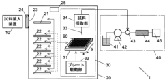
- 1 is a schematic configuration diagram showing an embodiment of a chromatograph having a sample charging device according to the present invention;
- FIG. 1 is a top view showing the configuration of an embodiment of a sample charging device according to the present invention, showing a state in which a moving table is at a first position;
- FIG. FIG. 4 is a top view showing the state of the sample loading device of the present embodiment when the moving table is at the second and third positions;
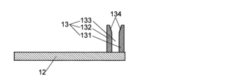
- FIG. 4 is an enlarged top view of a moving table and an engaging portion of the sample loading device of the present embodiment; Enlarged B-B cross-sectional view of the moving base and the engaging portion. The enlarged view which shows the state which engaged the flange of the sample accommodation part with the engaging part.
- FIG. 2B is a cross-sectional view along line B-B showing a state in which the moving table is at the first position in the sample charging apparatus of the present embodiment; BB sectional view showing the state when the moving table is at the second position. BB sectional view showing the state when the moving table is at the third position.
- FIG. 4 is a cross-sectional view taken along line C-C showing a state in which the moving table is at the first position in the sample loading device of the present embodiment; CC sectional view showing a state when the moving table is at the second position. CC cross-sectional view showing a state when the moving table is in the third position.
- FIG. 2B is a cross-sectional view along line B-B showing a state in which charging of the microplate into the sample container is completed in the sample charging device of the present embodiment.
- FIG. 11 is a top view showing an example in which a notch is provided at the tip of the internal mounting table on the side of the sample loading/unloading port in the sample loading device of the modified example.
- This sample storage unit 90 is a microplate conforming to the ANSI/SBS standard established by the Society for Biomolecular Screening (SBS) and approved by the American National Standards Institute (ANSI). be.
- SBS Society for Biomolecular Screening
- ANSI American National Standards Institute
- ANSI/SBS 3-2004 prescribes that a flange protruding from the outer periphery of the microplate and extending downward at its tip is provided (Non-Patent Document 1).
- the sample storage portion 90 includes a main body portion 91 provided with a plurality of wells 911 (96 in the example of FIG.
- flange 93 is provided over the entire circumference of the main body portion 91 in the example shown here, it may be provided only on a part of the outer peripheral portion of the main body portion 91 .
- similar flanges provided in compliance with ANSI/SBS standards are also widely used in sample storage units such as vial racks other than microplates.
- a sample storage unit such as a vial rack can be handled by the analyzer of this embodiment.
- FIG. 2 shows an outline of the configuration of the chromatograph, which is the analyzer of this embodiment.
- This chromatograph 1 includes a sample loading device (sample loading section) 10 , a sample container 20 , an autosampler 30 and a liquid chromatograph (LC) section 40 .
- sample loading section sample loading section
- LC liquid chromatograph
- the sample container 20 has an internal mounting table 21 and a sample storage shelf 22 arranged therein, and an opening (sample loading/unloading port) 23 is provided in a part of the side wall.
- the autosampler 30 is also arranged inside the sample container 20 .
- the internal mounting table 21 is designed to accommodate a sample when the sample container 90 is loaded into the sample container 20 by the sample loading device 10 and immediately before the sample container 90 is taken out of the sample container 20 . It is a stand on which the part 90 is placed.
- the upper surface of the internal mounting table 21 is positioned at the same height as the sample loading/unloading port 23 .
- the sample storage shelf 22 stores the sample until the sample storage unit 90 loaded in the sample storage chamber 20 is transferred to the autosampler 30 and after the sample in the sample storage unit 90 is collected by the autosampler 30. This shelf stores the sample storage section 90 until it is taken out of the storage 20 .
- sample storage shelf 22 is provided below the internal mounting table 21 in this embodiment, the position of the internal mounting table 21 is not limited to this example as long as it is inside the sample storage chamber 20 .
- a manipulator (not shown) moves the sample container 90 between the internal mounting table 21 and the sample storage shelf 22 and between the sample storage shelf 22 and the autosampler 30 .
- the opening/closing door (opening/closing part) 24 is a door that closes the sample loading/unloading port 23 from the outside of the sample container 20, and the sample loading/unloading is performed by descending from the height of the sample loading/unloading port 23 to a predetermined position (open position).
- the sample loading/unloading port 23 is closed by opening the sample loading/unloading port 23 and moving the sample loading/unloading port 23 from the opened state to a predetermined position (closed position).
- the opening/closing door 24 is lifted/lowered by the operation of the carriage tilting/opening/closing door lifting/lowering motor 1521, as will be described later.
- the sample storage chamber 20 is further provided with a heat retaining device 25 that heats and/or cools the interior of the chamber to maintain the temperature within the predetermined temperature range.
- the autosampler 30 includes a sample plate 31 on which a sample containing portion 90 is placed, a plate moving portion 32 that moves the sample plate 31 in mutually orthogonal X-axis directions and Y-axis directions, a needle 33, and a needle 33.
- a sampling unit 34 including an elevating mechanism and the like is provided.
- the plate moving unit 32 sequentially moves a plurality of wells 911 (or vials, etc.; the same shall apply hereinafter) of the sample storage unit 90 placed on the sample plate 31 directly below the needles 33, and the needles 33 move to the respective wells. Each time 911 reaches directly below, it descends to the well 911 and aspirates a liquid sample.
- the sampled liquid sample is supplied to the injector 43 of the LC section 40 described below.
- the LC unit 40 includes a mobile phase container 41 in which a mobile phase is stored, a pump 42 that sucks the mobile phase in the mobile phase container 41 and supplies it at a substantially constant flow rate, and a sample solution that is injected into the mobile phase. a column 44 that temporally separates various components contained in the sample solution injected into the mobile phase; and a detector 45 that sequentially detects the various components separated by the column 44.
- Detector 45 can be a mass spectrometer, a photodiode array (PDA) detector, an ultraviolet-visible spectrophotometric detector, or the like.
- the autosampler 30 and the LC section 40 have the same configurations as the autosampler and LC section of a conventional liquid chromatograph. Configurations different from those described above can also be applied to the autosampler 30 and the LC section 40 .
- a mechanism may be added to add a solvent to the sample, a reagent for causing a chemical reaction in the sample, or the like.
- a gas chromatograph may be used in place of the liquid chromatograph (LC section 40), and the autosampler 30 may collect the gas sample enclosed in the vial bottle of the sample storage section.
- the configuration of the sample charging device 10 will be described in detail below with reference to FIGS. 3 to 6.
- FIG. The sample loading device 10 is provided outside the sample container 20, and includes an external mounting table 11, a moving table 12, an engaging portion 13, an auxiliary mounting table 14, and a moving table moving mechanism (driving portion) 15. and
- the external mounting table 11 has a rectangular parallelepiped box-shaped main body 111, moving table guide rails 112, and auxiliary mounting table support rails 113 (Fig. 3A).
- the main body 111 is provided so that one of the short sides of the rectangular top face faces the sample loading/unloading port 23 .
- the front, rear, left, and right are defined with the end of the external mounting table 11 on the side of the sample loading/unloading port 23 as the front side.
- a portion of the main body 111 including the front side surface and the end portion of the upper surface near the sample loading/unloading port 23 is an opening, and the moving table 12 and the auxiliary mounting table 14 are arranged near the opening on the upper surface side.
- the moving base guide rails 112 and the auxiliary mounting base support rails 113 extend in the front-rear direction, and are provided in the main body 111 two by two in parallel in the lateral direction.
- the moving table guide rails 112 are arranged below the auxiliary table support rails 113 .
- the moving table 12 consists of a rectangular plate-like member (Figs. 4A and 4B), and is arranged with one short side of the rectangle facing forward.
- the rear end of the carriage 12 protrudes from the rectangular shape in the left and right sides, and gripping portions 121 provided at the ends of the protrusions hold the carriage guide rails 112 (FIG. 3A).
- illustration of the moving base guide rail 112 and the grip portion 121 is omitted in the drawings other than FIG. 3A.
- the engaging portion 13 is provided near the front end of the upper surface of the moving table 12, and has a first claw portion 131 and a second claw portion 132 extending upward from the upper surface of the moving table 12 (FIGS. 4A and 4B). .
- the second claw portion 132 is arranged behind the first claw portion 131 with a gap 133 therebetween.
- the gap 133 is set larger than the thickness of the flange 93 of the microplate 90 .
- Each of the first claw portion 131 and the second claw portion 132 is provided with a taper 134 formed in a shape such that the surface on the side of the gap 133 becomes farther away from the gap 133 from the vicinity of the center in the height direction toward the upper end.
- the taper 134 may be provided on only one of the first claw portion 131 and the second claw portion 132 .
- the auxiliary mounting table 14 consists of a rectangular plate-shaped member placed on the auxiliary mounting table support rails 113, and a rectangular hole 141 is provided in the center of the plate-shaped member.
- the rectangular shape of these plate members and the hole 141 is provided so that one short side faces the front side.
- the engaging portion 13 is arranged inside the hole 141 of the auxiliary mounting table 14 when viewed from above, and the upper end of the engaging portion 13 extends above the upper surface of the auxiliary mounting table 14 .
- the upper surface of the moving table 12 is below the upper surface of the auxiliary mounting table 14 .
- the moving table moving mechanism 15 consists of a moving table linear moving mechanism 151 and a moving table tilting mechanism 152 .
- the moving table linear movement mechanism 151 is composed of a motor and a mechanism for converting the rotary motion of the motor into linear motion, and linearly moves the moving table 12 in the front-rear direction by the linear motion.
- the auxiliary table 14 is also moved linearly in the front-rear direction by the moving table linear movement mechanism 151 .
- the moving table 12 moves between a first position (FIGS. 3A, 5A, 6A) away from the internal mounting table 21 and a second position (FIGS. 3B, 5B, 5B) approaching the internal mounting table 21. 6B).
- the engaging part 13 When the moving table 12 is at the first position, the engaging part 13 is arranged outside the sample container 20, and when the moving table 12 is at the second position, the engaging part 13 is arranged inside the sample container 20. . Also, the front end of the auxiliary mounting table 14 moves between the outside of the sample container 20 and the inside of the sample container 20 .
- moving the auxiliary table 14 is not essential in the present invention, and only the moving table 12 (and the engaging portion 13 fixed thereto) may be moved in the front-rear direction. In that case, it is preferable to open the front end of the hole 141 of the auxiliary table 14 and allow the engaging portion 13 to pass through the open portion and reach the inside of the sample container 20 as in the present embodiment. . Furthermore, the auxiliary mounting table 14 may be omitted.
- the moving table tilting mechanism 152 includes a moving table tilting/opening/closing door lifting motor 1521, a mechanism (not shown) that converts the rotary motion of the motor into vertical linear motion, and a mechanism that moves vertically by the linear motion. and a connector 1522 .
- a substantially horizontal rotating shaft 114 extending in the left-right direction is provided on the side surface of the external mounting table 11 at a position closer to the front than the center of gravity. Further, a plate member 115 extending downward and forward is fixed to the side surface of the external mounting table 11, and a projection 116 is fixed to the front end of the plate member 115 and forward and downward of the rotating shaft 114 ( Figure 6).
- the abutment member 1522 is fixed to the side surface of the opening/closing door 24 .
- the connecting rod 241 extending below the opening/closing door 24 moves up and down.
- the opening/closing door 24 is lowered from the closed position (FIG. 6A) where the opening/closing door 24 closes the sample loading/unloading port 23 to the open position where the entire sample loading/unloading port 23 is just opened, the abutment 1522 is not attached to the projection 116. No contact (Fig. 6B).
- the moving table 12 and the like are tilted as described above (FIG. 6C).
- the position of the moving table 12 when the moving table 12 is tilted from the second position corresponds to the above-described third position.
- the opening/closing operation of the opening/closing door 24 and the tilting operation of the external mounting table 11, the moving table 12, etc. can be performed by the same motor (moving table tilting/opening/closing door lifting/lowering motor 1521). , the equipment cost can be reduced.
- the projection 116 is pushed backward by the abutment member 1522, but the abutment member 1522 may push the projection 116 downward. Further, instead of fixing the abutment member 1522 to the open/close door 24, the contact member 1522 may be fixed to the connecting rod 241.
- the carriage 12 is placed at the first position when starting a new charging operation. state. Further, the sample loading/unloading port 23 is closed by the opening/closing door 24 . In this state, the sample containing portion 90 is placed on the moving table 12 and the auxiliary mounting table 14, and the flange 93 of the sample containing portion 90 and the engaging portion 13 of the moving table 12 are engaged (Figs. 6A).
- the auxiliary mounting table 14 supports a portion including the side portion of the sample holding portion 90 (the lateral end portion with respect to the direction in which the moving table 12 moves between the first position and the second position as described later). do.
- the moving table tilting and opening/closing door lifting motor 1521 is operated, and the opening/closing door 24 is lowered to a position where the abutment member 1522 does not contact the protrusion 116 while the sample loading/unloading port 23 is opened.
- the moving table linear movement mechanism 151 moves the moving table 12 and the auxiliary mounting table 14 forward, that is, in a direction approaching the internal mounting table 21, and moves the moving table 12 to the second position. 2 positions (FIGS. 3B, 5B, 6B).
- the engaging portion 13 is arranged immediately after the internal mounting table 21 , and most of the sample containing portion 90 except for the first engaging portion 931 is mounted on the internal mounting table 21 .
- the abutment member 1522 does not abut on the projection 116 as described above, the moving table 12 is not tilted.
- the carriage tilting mechanism 152 operates the carriage tilting/opening/closing door lifting motor 1521 to further lower the abutment member 1522 (and the opening/closing door 24 to which it is fixed), and move the abutment member 1522 to the protrusion 116 .
- the external mounting table 11, the moving table 12, etc. are tilted (FIGS. 5C and 6C).
- the movable table 12 is placed at the third position, and the engagement between the flange 93 of the sample holding portion 90 and the engaging portion 13 of the movable table 12 is disengaged, resulting in a non-engaged state.
- the moving table 12 and the auxiliary mounting table 14 are moved away from the internal mounting table 21 by the moving table linear movement mechanism 151 .
- the movable table tilting mechanism 152 operates the movable table tilting/opening/closing door lifting motor 1521 to raise the opening/closing door 24 and the abutment member 1522, thereby canceling the inclination of the external mounting table 11, the moving table 12, and the like.
- the opening/closing door 24 closes the sample loading/unloading port 23 . As a result, the carriage 12 returns to the first position.
- the sample storage unit 90 is loaded into the sample storage chamber 20, and the sample loading device 10 returns to its initial state (Fig. 7).
- the operations may be performed in the reverse order of the insertion.
- the take-out operation starts from a state in which the sample containing portion 90 transferred from the autosampler 30 or the sample storage shelf 22 is placed on the internal mounting table 21 , but the sample containing portion 90 is not necessarily placed on the internal mounting table 21 . It is not always placed in a fixed position, and some positional deviation may occur.
- the position of the sample containing portion 90 on the internal mounting table 21 can be shifted back and forth.
- the flange 93 can be engaged with the engaging portion 13 even if it is slightly deviated in the direction.
- Positional deviation in the left-right direction can be dealt with by providing the first claw portion 131 and the second claw portion 132 with a certain length in the left-right direction (FIG. 4A).
- the sample storage unit 90 storing a plurality of samples in advance can be easily loaded into the sample storage chamber 20 and taken out at once.
- the time during which the opening/closing door 24 of the sample loading/unloading port 23 of 20 is open can be minimized, and the temperature change and condensation in the sample container 20 can be minimized.
- the time during which the opening/closing door 24 is open could be suppressed to about 10 to 20 seconds.
- the microplate 90 is carried in while adjusting the temperature inside the sample container 20 so as to cool it to a temperature within the range of 5 to 7°C in an environment where the room temperature is 25°C. I did an experiment.
- the opening time of the open/close door 24 is set to 10 seconds, and the temperature in the sample storage chamber 20 and the temperature of the sample in the microplate previously stored in the sample storage shelf 22 separately from the microplate 90 to be carried in are different. Time change was measured.
- the burden on the operator can be further reduced.
- the work time can be further shortened.
- the moving table is moved to the third position inclined with respect to the surface of the external mounting table, and the flange of the sample plate and the engaging portion of the moving table are in the non-engaged state.
- the present invention is not limited to this, but provides a mechanism for changing the engagement state between the flange of the sample plate and the engagement portion of the moving table. For example, if the engaging portion projects from the moving table by an electrical or mechanical mechanism and is retracted into the moving table, the engaging state can be changed without tilting the moving table. be able to.
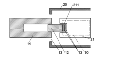
- a notch 211 may be provided at the end of the internal mounting table 21 on the side of the sample loading/unloading port 23 (FIG. 8).
- the tip of the moving table 12 reaches the inside of the notch 211 , so that the sample containing section 90 can reach a deeper position on the internal mounting table 21 .
- the portion of the sample containing portion 90 supported by the internal mounting table 21 becomes wider. Therefore, the sample containing section 90 can be mounted on the internal mounting table 21 more stably.
- the heat-retaining device 25 is provided to maintain the temperature within the sample container 20 within a predetermined temperature range. good. In such a case, the temperature change in the sample container 20 due to the opening of the opening/closing door 24 does not pose a problem, but the sample loading device of the present embodiment enables the sample to be stored quickly while reducing the operational burden on the operator. Parts can be loaded and unloaded.
- the sample analysis device is a chromatograph. can.
- the analysis device is a sample container having an opening/closing portion and including therein an internal mounting table for receiving the sample containing portion via the opening/closing portion; a sample loading unit for loading the sample storage unit into the sample storage;
- the sample containing portion has a plane direction and has a flange provided at an end in the plane direction,
- the sample loading unit is an external mounting table provided outside the sample storage and having a surface; a first position spaced apart from the internal mounting table and a second position closer to the internal mounting table on the surface of the external mounting table; a carriage having an engaging portion that engages with the flange of the and a driving section that moves the movable table and changes the engagement state between the flange of the sample containing section and the engaging section of the movable table.
- the operator stores the sample in advance in the sample storage unit, and when inserting the sample storage unit into the sample storage, moves the sample storage unit to the moving table at the first position. It is only necessary to place the specimen on the top and engage the flange of the sample holding portion with the engaging portion of the moving table.
- the sample charging device automatically opens the opening/closing door section, moves the moving table to the second position by the moving section, closes the opening/closing section, and disengages the flange and the engaging section by the driving section.
- the sample container is inserted into the sample container only by engaging the two. The same is true when the sample container is taken out of the sample container. from the second position to the first position to close the closure.
- the operator only needs to pick up from the moving table the sample holding part which is placed on the moving table moved to the first position and whose flange is engaged with the engaging part. In this way, the operation of inserting the sample into the sample container and removing it from the sample container can be easily performed collectively by the operation of inserting and removing the sample container from the sample container. temperature change and condensation in the sample storage can be minimized.
- the analysis device is the analysis device according to the first aspect, wherein the drive unit moves the movable table from the first position, the second position, and the second position to the flange. and the engaging portion are disengaged from each other.
- the flange and the engaging portion can be easily disengaged by inclining the movable table. Further, the flange and the engaging portion can be easily brought into the engaged state by canceling the inclination of the carriage.
- the analysis device is the analysis device according to paragraph 2, the external mounting table comprises a pivot axis that is substantially horizontal and substantially vertical to a direction of movement of the carriage between the first position and the second position;
- the sample container has a sample loading/unloading port that is an opening through which the sample storage unit passes,
- the opening/closing unit includes an opening/closing door capable of moving up and down between a closed position that closes the sample loading/unloading port and an open position that is lower than the closed position and opens the sample loading/unloading port,
- the driving unit includes an elevation driving unit that lowers and raises a portion of the external mounting table closer to the second position than the rotation shaft and lowers and raises the open/close door.
- the elevation driving section lowers the portion of the external mounting table closer to the second position than the rotating shaft, thereby moving the external mounting table and the moving table on the external mounting table. is tilted and the portion near the second position is lifted to release the tilt of the external mounting table and the moving table.
- the elevation driving unit opens the sample loading/unloading port by lowering the opening/closing door of the opening/closing unit from the closed position to the open position, and closes the sample loading/unloading port by raising the opening/closing door from the open position to the closed position.
- the inclination and the cancellation of the inclination of the moving table and the opening and closing of the opening/closing section can be performed by the same elevation driving section, so that the apparatus cost can be suppressed.
- the analysis apparatus according to item 4 is the analysis apparatus according to any one of items 1 to 3, further comprising: An auxiliary mounting table is provided on the external mounting table for supporting the lateral end portion with respect to the direction of movement.
- the analysis apparatus according to item 5 is the analysis apparatus according to item 4, wherein the auxiliary mounting table moves with the moving table as the moving table moves between the first position and the second position. It is possible to move in the same direction.
- the external mounting table when the moving table is moved from the first position to the second position (or vice versa), the external mounting table also moves closer to the internal mounting table (or vice versa). By doing so, the sample storage section can be moved while being stably supported on the external mounting table.
- the analysis apparatus of item 5 since the auxiliary auxiliary mounting table is also moved along with the movement of the movable table, the sample container can be moved while being supported more stably.
- the analyzer according to item 6 is the analyzer according to any one of items 1 to 5, wherein the engaging part moves the movable table between the first position and the second position. Equipped with two claws arranged side by side with a gap in the movement direction, and one or both of the two claws has a shape in which the surface on the side of the gap moves away from the gap toward the upper end. It has a taper formed in the
- the flange of the sample storage section extends along the taper by 2 degrees. Since it is introduced into the gap between the claws, the flange and the engaging portion can be engaged.
- the analysis device is the analysis device according to any one of paragraphs 1 to 6, further: a sample collection unit that collects the sample stored in the sample storage unit inserted in the sample storage; and an analysis unit that analyzes the sample collected by the sample collection unit.
- the analyzer according to item 8 is the analyzer according to item 7, wherein the analysis unit is a chromatograph.
- sample analyzers since the sample loading section is provided, volatilization of the solvent, decomposition of the solute, precipitation of the solute, etc. in the sample collected by the sampling section are prevented. It is possible to suppress the occurrence of this, and to perform more accurate analysis in the analysis section (the chromatograph in the analysis apparatus according to item 8).
Landscapes
- Physics & Mathematics (AREA)
- Health & Medical Sciences (AREA)
- Life Sciences & Earth Sciences (AREA)
- Chemical & Material Sciences (AREA)
- Analytical Chemistry (AREA)
- Biochemistry (AREA)
- General Health & Medical Sciences (AREA)
- General Physics & Mathematics (AREA)
- Immunology (AREA)
- Pathology (AREA)
- Automatic Analysis And Handling Materials Therefor (AREA)
Priority Applications (3)
| Application Number | Priority Date | Filing Date | Title |
|---|---|---|---|
| US18/689,263 US20240377366A1 (en) | 2021-09-10 | 2022-06-02 | Analysis device |
| JP2023546775A JP7552920B2 (ja) | 2021-09-10 | 2022-06-02 | 分析装置 |
| CN202280059282.5A CN118043676A (zh) | 2021-09-10 | 2022-06-02 | 分析装置 |
Applications Claiming Priority (2)
| Application Number | Priority Date | Filing Date | Title |
|---|---|---|---|
| JP2021-148127 | 2021-09-10 | ||
| JP2021148127 | 2021-09-10 |
Publications (1)
| Publication Number | Publication Date |
|---|---|
| WO2023037674A1 true WO2023037674A1 (ja) | 2023-03-16 |
Family
ID=85506389
Family Applications (1)
| Application Number | Title | Priority Date | Filing Date |
|---|---|---|---|
| PCT/JP2022/022521 Ceased WO2023037674A1 (ja) | 2021-09-10 | 2022-06-02 | 分析装置 |
Country Status (4)
| Country | Link |
|---|---|
| US (1) | US20240377366A1 (https=) |
| JP (1) | JP7552920B2 (https=) |
| CN (1) | CN118043676A (https=) |
| WO (1) | WO2023037674A1 (https=) |
Cited By (1)
| Publication number | Priority date | Publication date | Assignee | Title |
|---|---|---|---|---|
| JPWO2024004385A1 (https=) * | 2022-06-29 | 2024-01-04 |
Citations (5)
| Publication number | Priority date | Publication date | Assignee | Title |
|---|---|---|---|---|
| US5416329A (en) * | 1990-05-08 | 1995-05-16 | Wallac Oy | Apparatus for counting liquid scintillation samples |
| JP2004180675A (ja) * | 2002-11-19 | 2004-07-02 | Sanyo Electric Co Ltd | インキュベータ |
| JP2008533989A (ja) * | 2005-03-22 | 2008-08-28 | アイアールエム・リミテッド・ライアビリティ・カンパニー | 化合物をプロファイル解析するデバイス、システムおよび関連方法 |
| WO2020039558A1 (ja) * | 2018-08-23 | 2020-02-27 | 株式会社島津製作所 | プレート搬送装置およびプレートチェンジャー |
| WO2020090159A1 (ja) * | 2018-11-02 | 2020-05-07 | 株式会社島津製作所 | 試料前処理装置、該装置を備えた分析システム、及びオートサンプラ |
Family Cites Families (5)
| Publication number | Priority date | Publication date | Assignee | Title |
|---|---|---|---|---|
| DE60144160D1 (de) * | 2000-12-18 | 2011-04-14 | Protedyne Corp | Extrudieren von gel für gel elektrophorese |
| EP3693720B1 (en) * | 2019-02-11 | 2023-01-11 | Heraeus Electro-Nite International N.V. | Method and apparatus for demolding and analyzing a direct analysis sample |
| WO2021021700A1 (en) * | 2019-07-29 | 2021-02-04 | Waters Technologies Corporation | Interface module for robotic loading and unloading of a sample manager for liquid chromatography |
| CN212060277U (zh) * | 2019-12-26 | 2020-12-01 | 深圳迈瑞生物医疗电子股份有限公司 | 样本分析单元、流水线样本传送系统及样本分析系统 |
| GB2592590B (en) * | 2020-03-02 | 2024-02-14 | Agilent Technologies Inc | Sample processing with information detection during transfer of a sample container |
-
2022
- 2022-06-02 CN CN202280059282.5A patent/CN118043676A/zh active Pending
- 2022-06-02 WO PCT/JP2022/022521 patent/WO2023037674A1/ja not_active Ceased
- 2022-06-02 JP JP2023546775A patent/JP7552920B2/ja active Active
- 2022-06-02 US US18/689,263 patent/US20240377366A1/en active Pending
Patent Citations (5)
| Publication number | Priority date | Publication date | Assignee | Title |
|---|---|---|---|---|
| US5416329A (en) * | 1990-05-08 | 1995-05-16 | Wallac Oy | Apparatus for counting liquid scintillation samples |
| JP2004180675A (ja) * | 2002-11-19 | 2004-07-02 | Sanyo Electric Co Ltd | インキュベータ |
| JP2008533989A (ja) * | 2005-03-22 | 2008-08-28 | アイアールエム・リミテッド・ライアビリティ・カンパニー | 化合物をプロファイル解析するデバイス、システムおよび関連方法 |
| WO2020039558A1 (ja) * | 2018-08-23 | 2020-02-27 | 株式会社島津製作所 | プレート搬送装置およびプレートチェンジャー |
| WO2020090159A1 (ja) * | 2018-11-02 | 2020-05-07 | 株式会社島津製作所 | 試料前処理装置、該装置を備えた分析システム、及びオートサンプラ |
Cited By (3)
| Publication number | Priority date | Publication date | Assignee | Title |
|---|---|---|---|---|
| JPWO2024004385A1 (https=) * | 2022-06-29 | 2024-01-04 | ||
| WO2024004385A1 (ja) * | 2022-06-29 | 2024-01-04 | 株式会社日立ハイテク | 検体昇降機構および検体搬送装置 |
| JP7732100B2 (ja) | 2022-06-29 | 2025-09-01 | 株式会社日立ハイテク | 検体昇降機構および検体搬送装置 |
Also Published As
| Publication number | Publication date |
|---|---|
| JP7552920B2 (ja) | 2024-09-18 |
| CN118043676A (zh) | 2024-05-14 |
| JPWO2023037674A1 (https=) | 2023-03-16 |
| US20240377366A1 (en) | 2024-11-14 |
Similar Documents
| Publication | Publication Date | Title |
|---|---|---|
| US12060223B2 (en) | Automated cryogenic storage system | |
| US11175298B2 (en) | Automated system for storing, retrieving and managing samples | |
| US7635246B2 (en) | Device and method for retrieving or replacing a tray within a storage compartment | |
| JP5829643B2 (ja) | 分析装置 | |
| KR20200135462A (ko) | 자동화된 극저온 저장 및 인출 시스템 | |
| JP2010032516A (ja) | 試料試験管ラックを取り扱う研究室システム、試料試験管ラックの配列要素およびラックトレイ受承組立体 | |
| WO2023037674A1 (ja) | 分析装置 | |
| EP3349014B1 (en) | Sample heating device | |
| JPWO2016027330A1 (ja) | オートサンプラ及びこれを備えた分析装置 |
Legal Events
| Date | Code | Title | Description |
|---|---|---|---|
| 121 | Ep: the epo has been informed by wipo that ep was designated in this application |
Ref document number: 22867004 Country of ref document: EP Kind code of ref document: A1 |
|
| WWE | Wipo information: entry into national phase |
Ref document number: 2023546775 Country of ref document: JP |
|
| WWE | Wipo information: entry into national phase |
Ref document number: 202280059282.5 Country of ref document: CN |
|
| WWE | Wipo information: entry into national phase |
Ref document number: 18689263 Country of ref document: US |
|
| NENP | Non-entry into the national phase |
Ref country code: DE |
|
| 122 | Ep: pct application non-entry in european phase |
Ref document number: 22867004 Country of ref document: EP Kind code of ref document: A1 |