WO2023033192A2 - テープカッター - Google Patents
テープカッター Download PDFInfo
- Publication number
- WO2023033192A2 WO2023033192A2 PCT/JP2023/001852 JP2023001852W WO2023033192A2 WO 2023033192 A2 WO2023033192 A2 WO 2023033192A2 JP 2023001852 W JP2023001852 W JP 2023001852W WO 2023033192 A2 WO2023033192 A2 WO 2023033192A2
- Authority
- WO
- WIPO (PCT)
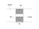
- Prior art keywords
- tape cutter
- tape
- sticking
- cutting blade
- width
- Prior art date
- Legal status (The legal status is an assumption and is not a legal conclusion. Google has not performed a legal analysis and makes no representation as to the accuracy of the status listed.)
- Ceased
Links
Images






Classifications
-
- B—PERFORMING OPERATIONS; TRANSPORTING
- B65—CONVEYING; PACKING; STORING; HANDLING THIN OR FILAMENTARY MATERIAL
- B65H—HANDLING THIN OR FILAMENTARY MATERIAL, e.g. SHEETS, WEBS, CABLES
- B65H35/00—Delivering articles from cutting or line-perforating machines; Article or web delivery apparatus incorporating cutting or line-perforating devices, e.g. adhesive tape dispensers
- B65H35/0006—Article or web delivery apparatus incorporating cutting or line-perforating devices
Definitions
- the present invention relates to a tape cutter for adhesive tape.
- Patent Document 1 As a conventional tape cutter, there is one described in Patent Document 1, for example.
- the tape cutter described in the same document includes a holding part that rotatably holds a tape roll formed by winding an adhesive tape around a core, and a sticking part that sticks the leading end of the adhesive tape pulled out from the tape roll. (temporary fastening portion) and a cutting blade for cutting the adhesive tape.
- the sticking portion is provided between the holding portion and the cutting blade.
- the adhesive tape is fed out by pinching the adhesive tape with fingers and pulling it toward the tip side.
- it is necessary to secure a sufficient space between the holding portion and the sticking portion for inserting the fingers. Therefore, the distance from the holding portion to the cutting blade must be increased. This has been a factor hindering the miniaturization of conventional tape cutters.
- the present invention has been made in view of the above problems, and an object of the present invention is to provide a tape cutter having a structure suitable for miniaturization.
- a tape cutter according to the present invention is a tape cutter for a wound adhesive tape, and includes a holding portion that rotatably holds the wound portion of the adhesive tape, and a holding portion that is pulled out from the wound portion of the adhesive tape a cutting blade that cuts the lead-out portion, which is a part, and an adhering portion that is positioned between the winding portion and the cutting blade and to which a part of the lead-out portion of the adhesive tape is affixed, The width of the sticking portion is smaller than the width of the adhesive tape.
- the width of the sticking part is smaller than the width of the adhesive tape.
- a tape cutter with a structure suitable for miniaturization is realized.
- FIG. 1 is a side view of one embodiment of a tape cutter according to the present invention
- FIG. FIG. 2 is a plan view showing the tape cutter of FIG. 1
- 3 is a plan view for explaining dimensions and the like of the sticking portion 30.
- FIG. 3 is a side view showing a cutting blade 20, a sticking portion 30 and an adhesive tape 90;
- FIG. 3 is a side view for explaining an example of how to use the tape cutter of FIG. 1;
- FIG. 3 is a side view for explaining an example of how to use the tape cutter of FIG. 1;
- FIG. 3 is a plan view for explaining the effect of the tape cutter of FIG. 1; It is a top view for demonstrating the modification of the sticking part 30.
- FIG. It is a side view which shows the modification of the tape cutter of FIG.
- FIG. 10 is a plan view showing an overhanging portion 50 in the tape cutter of FIG. 9;
- the tape cutter 1 is a tape cutter for a wound adhesive tape 90 and is used to pay out and cut the adhesive tape 90 .
- the tape cutter 1 may be of a hand-held type or a desktop type.
- the adhesive tape 90 is wound around an annular core.
- the adhesive tape 90 may be provided with an adhesive surface only on the lower surface, or may be provided with an adhesive surface on both surfaces (upper surface and lower surface). Examples of the former include cellophane tape. Examples of the latter include, for example, double-sided tape.
- the adhesive surface of the double-sided tape may be exposed only on the lower surface, or may be exposed on both surfaces. In the former double-sided tape, a release paper is attached to the upper surface.
- the tape cutter 1 includes a holding portion 10 , a cutting blade 20 , an adhering portion 30 and an arm portion 40 .
- the holding portion 10 rotatably holds the winding portion 92 of the adhesive tape 90 .
- the wound portion 92 is a portion wound around the core of the adhesive tape 90 and has an annular shape as a whole. The lower surface of each portion of the winding portion 92 is adhered to the upper surface or core of the other portion of the winding portion 92 .
- the holding portion 10 has a side plate portion 12 and a shaft portion 14 .
- the side plate portion 12 covers the adhesive tape 90 from the sides.
- the side plate portions 12 may be provided on both sides of the adhesive tape 90, or may be provided on only one side.
- the side plate portion 12 may cover the entire adhesive tape 90 from the side, or may cover only a portion thereof. That is, the side plate portion 12 may overlap the entire adhesive tape 90 or may overlap only a portion of the adhesive tape 90 in a side view.
- the shaft part 14 supports the adhesive tape 90 while being inserted inside the core of the adhesive tape 90 .
- the shaft portion 14 may be fixed to the side plate portion 12 or may be provided rotatably with respect to the side plate portion 12 . In the former case, the adhesive tape 90 rotates independently when it is paid out. In the latter case, the adhesive tape 90 rotates together with the shaft portion 14 when unwound.
- the shaft portion 14 is preferably molded integrally with the side plate portion 12 .
- plastic, metal, wood, or paper can be used as a material of the holding part 10.
- the plastic may be a biodegradable plastic. Papers also include processed papers and cellulose nanofibers (CNF).
- the cutting blade 20 cuts the lead-out portion 94 of the adhesive tape 90 .
- the pull-out portion 94 is a portion of the adhesive tape 90 pulled out from the winding portion 92 . Therefore, the lower surface of the lead-out portion 94 is attached neither to the upper surface of the wound portion 92 nor to the core.
- the cutting blade 20 is arranged apart from the winding portion 92 . Thereby, the cutting blade 20 cuts the lead-out portion 94 leaving a certain length of the lead-out portion 94 . When cutting the lead-out portion 94 , the cutting blade 20 contacts the lower surface of the lead-out portion 94 .
- the material of the cutting blade 20 may be the same as or different from the material of the holding portion 10 .
- the cutting blade 20 may be molded integrally with the holding portion 10 .
- the sticking portion 30 is positioned between the winding portion 92 (holding portion 10 ) and the cutting blade 20 . In this embodiment, the sticking portion 30 is separated from the cutting blade 20 .
- a part of the lead-out portion 94 is attached to the attaching portion 30 . Specifically, a portion of the lower surface of the lead-out portion 94 is attached to the attachment surface 32 of the attachment portion 30 .
- the sticking surface 32 is equal to the upper surface of the sticking portion 30 .
- the sticking surface 32 is planar.
- the portion of the lead-out portion 94 (the portion adhered to the sticking portion 30) is present between the tip 94a and the base 94b of the lead-out portion 94. As shown in FIG.
- the material of the sticking portion 30 may be the same as or different from the material of the holding portion 10 .
- Width w ⁇ b>1 of sticking portion 30 is smaller than width w ⁇ b>2 of adhesive tape 90 . That is, the width w1 is designed to be smaller than the width w2 of the adhesive tape 90 that is assumed to be used in the tape cutter 1 .
- the width w1 is defined as the dimension of the sticking surface 32 in the width direction (the direction perpendicular to the extending direction of the lead-out portion 94).
- the width w1 is preferably 50% or less of the width w2, more preferably 20% or less.
- the width w1 is smaller than the width of the cutting blade 20. As shown in FIG.
- the width w1 is preferably 50% or less of the width of the cutting blade 20, more preferably 20% or less.
- the widthwise dimension of the sticking portion 30 is always smaller than the width w2 in the exposed area. That is, it is preferable that the widthwise dimension of the sticking portion 30 is smaller than the width w2 at any position in the height direction (the vertical direction in FIG. 1) of the sticking portion 30 in the exposed region.
- the exposed region means a region where the sticking portion 30 is exposed (a region that does not overlap with the holding portion 10 or the arm portion 40) in side view.
- the portion of the sticking portion 30 indicated by solid lines is the exposed region.
- the widthwise dimension of the sticking portion 30 may or may not be constant in the exposed area. In the former case, the widthwise dimension of the sticking portion 30 is equal to the width w1 at any position in the height direction of the sticking portion 30 in the exposed region.
- the length d1 of the sticking portion 30 is greater than the width w1.
- the length d1 is defined as the dimension of the sticking surface 32 in the extending direction of the lead-out portion 94. As shown in FIG.
- the length d1 is, for example, 5 mm or more and 15 mm or less.
- the bisecting plane P1 of the sticking portion 30 coincides with the bisecting plane P2 of the cutting blade 20 .
- the bisecting plane P1 is a plane perpendicular to the width direction that bisects the sticking surface 32 .
- the bisecting plane P2 is a plane perpendicular to the width direction that bisects the cutting blade 20 .
- FIG. 4 is a side view showing the cutting blade 20, the sticking portion 30 and the adhesive tape 90.
- FIG. As can be seen from the figure, the sticking surface 32 of the sticking portion 30 is positioned above the reference line L1 (first reference line) in a side view.
- the reference line L1 is a straight line passing through the base 94b of the lead-out portion 94 and the tip of the cutting blade 20 (the tip 94a of the lead-out portion 94).
- a height h1 of the sticking surface 32 from the reference line L1 is preferably 5 mm or more, and more preferably 10 mm or more.
- the height h1 is defined as the length of a perpendicular line drawn from a portion of the attachment surface 32 closest to the reference line L1 (in the case of this embodiment, an end portion 32b described later) to the reference line L1 in a side view. . Further, in a side view, the end portion 32a of the adhering surface 32 on the side of the cutting blade 20 (the side of the tip 94a) is located above the reference line L2 (second reference line).
- the reference line L2 is a straight line passing through the end portion 32b of the sticking surface 32 on the side of the holding portion 10 (the side of the root 94b) and the tip of the cutting blade 20. As shown in FIG.
- the arm part 40 connects the holding part 10 and the cutting blade 20 .
- the arm portion 40 extends from the holding portion 10 to the cutting blade 20 through the lower surface side of the drawer portion 94 .
- a space for inserting a finger exists above the arm portion 40 .
- the material of the arm portion 40 may be the same as or different from that of the holding portion 10 .
- the arm portion 40 is preferably molded integrally with the holding portion 10 .
- the sticking portion 30 is connected to the arm portion 40 . Specifically, the sticking portion 30 is erected on the arm portion 40 .
- the sticking part 30 is fixed so as not to move with respect to the arm part 40 .
- the sticking portion 30 may be molded integrally with the arm portion 40 .
- the pull-out portion 94 is pinched with fingers, and the pull-out portion 94 is peeled off from the cutting blade 20 and the adhering portion 30. Then, the adhesive tape 90 is extended until the pull-out portion 94 reaches a desired length. pull out Next, as shown in FIG. 6, the lead-out portion 94 is cut by pressing the lead-out portion 94 against the tip of the cutting blade 20 . After cutting, the lead-out portion 94 is stuck to the sticking portion 30 again. Further, the leading end 94a of the lead-out portion 94 is stuck to the cutting blade 20 (see FIG. 1).
- the lead-out portion 94 is stuck only to the cutting blade 20 and the sticking portion 30 . That is, the tape cutter 1 is configured so that the pull-out portion 94 is not adhered to a portion of the tape cutter 1 other than the cutting blade 20 or the adhered portion 30 .
- the width w ⁇ b>1 of the sticking portion 30 is smaller than the width w ⁇ b>2 of the adhesive tape 90 .
- a portion 94c that is not adhered to the adhered portion 30 is located in the same region R1 as the adhered portion 30 with respect to the extension direction of the lead-out portion 94 of the adhesive tape 90 (horizontal direction in FIG. 7). (A portion protruding from the sticking surface 32) exists.
- the portion 94c is hatched.
- the region R1 is a region in contact with the sticking surface 32 in side view. Since both sides of the portion 94c are exposed, it can be picked up with fingers.
- the tape cutter 1 having a structure suitable for miniaturization is realized.
- the length of the lead-out part 94 is shortened, so dust is less likely to adhere to the adhesive tape 90 .
- the lead-out portion 94 is attached to the sticking portion 30, even if the tip 94a of the lead-out portion 94 is separated from the cutting blade 20, the situation in which the lead-out portion 94 returns to the winding portion 92 is less likely to occur. be able to.
- the width w1 of the adhering portion 30 is smaller than the width w2 of the adhesive tape 90, the contact area with the adhesive tape 90 and, in turn, the adhesive force with the adhesive tape 90 can be adjusted by changing the width w1. can be done. This increases options for the material of the sticking portion 30, making it easier to integrally mold the sticking portion 30 with other parts (the holding portion 10, the cutting blade 20, and/or the arm portion 40).
- the width w1 is preferably 50% or less of the width w2, more preferably 20% or less.
- the width w1 is preferably 5% or more of the width w2.
- the widthwise dimension of the sticking portion 30 is always smaller than the width w2 in the exposed area, it is advantageous to ensure a wide space for inserting a finger under the portion 94c.
- the widthwise dimension of the sticking portion 30 is constant in the exposed region, the sticking portion 30 does not enter below the portion 94c in the exposed region, which is particularly advantageous for securing a wide space for inserting a finger. is.
- the sticking part 30 is separated from the cutting blade 20. This makes it difficult for fingers to touch the cutting blade 20 when pinching the portion 94c, so that the safety of the tape cutter 1 can be enhanced.
- the bisecting plane P1 of the sticking portion 30 coincides with the bisecting plane P2 of the cutting blade 20 .
- the lead-out portion 94 is supported substantially evenly in the width direction by the adhering portion 30, so that the cutting can be smoothly performed.
- the length d1 of the sticking portion 30 is greater than the width w1 of the sticking portion 30.
- the sticking surface 32 of the sticking portion 30 When viewed from the side, the sticking surface 32 of the sticking portion 30 is positioned above the reference line L1. In this case, it is possible to pinch the lead portion 94 above the reference line L1. By utilizing the space above the reference line L1 in this way, the distance from the holding part 10 to the cutting blade 20 can be easily shortened. Further, in this case, when the cutting blade 20 cuts the lead-out portion 94 , the sticking surface 32 strongly contacts the lower surface of the lead-out portion 94 .
- a larger height h1 of the adhering surface 32 from the reference line L1 is advantageous in utilizing the space above the reference line L1 and in bringing the adhering surface 32 into strong contact with the lower surface of the drawer portion 94.
- the height h1 is preferably 5 mm or more, more preferably 10 mm or more.
- the height h1 is preferably 30 mm or less.
- the end 32a of the sticking surface 32 is located above the reference line L2. In this case, when cutting the lead-out portion 94 with the cutting blade 20 , the entire sticking surface 32 strongly contacts the lower surface of the lead-out portion 94 .
- the tape cutter 1 is configured so that the pull-out portion 94 is not attached to a portion of the tape cutter 1 other than the cutting blade 20 or the attaching portion 30 .
- both sides of the adhesive tape 90 are exposed in the entire portion of the pull-out portion 94 that is not attached to the cutting blade 20 or the attaching portion 30 . This increases the percentage of the portion that can be picked with the fingers. This is also advantageous for shortening the distance from the holding part 10 to the cutting blade 20 .
- An arm portion 40 is provided on the tape cutter 1 . This makes it possible to realize the tape cutter 1 in which a predetermined distance is maintained between the holding portion 10 and the cutting blade 20 with a simple configuration.
- the manufacturing process of the tape cutter 1 can be simplified, thereby reducing the manufacturing cost of the tape cutter 1.
- the sticking part 30 is connected to the arm part 40 .
- the tape cutter 1 in which the adhering portion 30 is arranged between the winding portion 92 and the cutting blade 20 can be realized with a simple configuration.
- the manufacturing process of the tape cutter 1 can be simplified, thereby reducing the manufacturing cost of the tape cutter 1.
- the tape cutter 1 contains CNF as a material, it is advantageous for reducing the weight and increasing the strength of the tape cutter 1. Moreover, using CNF also contributes to reduction of environmental load.
- the adhesive tape 90 is a double-sided tape with adhesive surfaces exposed on both sides, dust tends to adhere to the upper surface of the drawer portion 94 compared to an adhesive tape with an adhesive surface exposed only on the lower surface. Therefore, the tape cutter 1 that can reduce the length of the lead-out portion 94 is particularly useful.
- the present invention is not limited to the above embodiments, and various modifications are possible.
- the case where the adhering portion 30 is separated from the cutting blade 20 is exemplified.
- the sticking portion 30 may be adjacent to the cutting blade 20 . In that case, it becomes easier to form the sticking portion 30 integrally with the cutting blade 20 .
- the bisecting plane P1 of the sticking portion 30 coincides with the bisecting plane P2 of the cutting blade 20 as an example.
- the bisecting plane P1 does not have to coincide with the bisecting plane P2, for example as shown in FIG.
- a portion 94c that is not stuck to the sticking portion 30 can be secured widely on one side of the sticking portion 30 (upper side in FIG. 8). . This makes it easier to pick up the portion 94c with fingers.
- length d1 of the sticking portion 30 is greater than the width w1 of the sticking portion 30 is exemplified.
- length d1 may be equal to width w1 or may be less than width w1.
- the sticking surface 32 of the sticking portion 30 is positioned above the reference line L1 in side view is exemplified.
- the sticking surface 32 may be positioned on the reference line L1 or may be positioned below the reference line L1.
- the lead-out portion 94 can be reliably attached to the attachment surface 32 by pressing the lead-out portion 94 against the attachment surface 32 from above with a finger.
- the case where the end 32a of the sticking surface 32 is located above the reference line L2 in side view is illustrated.
- the end portion 32a may be positioned on the reference line L2 or may be positioned below the reference line L2.
- the lead-out portion 94 can be reliably attached to the entire attachment surface 32 by pressing the lead-out portion 94 against the sticking surface 32 from above with a finger.
- the tape cutter 1 may be provided with an overhang portion 50 as shown in FIGS. 9 and 10, for example.
- FIG. 10 is a top view of the projecting portion 50 of FIG.
- the overhanging portion 50 overhangs the drawer portion 94 from the holding portion 10 .
- the projecting portion 50 extends above the sticking portion 30 . That is, the projecting portion 50 overlaps the sticking portion 30 in plan view.
- the projecting portion 50 overlaps the entire sticking portion 30 in plan view.
- the projecting portion 50 extends above the cutting blade 20 . That is, the projecting portion 50 overlaps the cutting blade 20 in plan view.
- the protruding portion 50 does not have to reach above the cutting blade 20 and does not have to reach above the sticking portion 30 .
- the protruding portion 50 By providing the protruding portion 50 in this manner, the effect of suppressing dust from adhering to the drawer portion 94 can be obtained.
- the projecting portion 50 extends above the sticking portion 30 , the above effect can be exerted over a wide range of the drawing portion 94 .
- the protruding portion 50 extends above the cutting blade 20 , the above effect can be exerted on substantially the entire drawn portion 94 .
Landscapes
- Adhesive Tape Dispensing Devices (AREA)
Priority Applications (2)
| Application Number | Priority Date | Filing Date | Title |
|---|---|---|---|
| JP2023505353A JP7473929B2 (ja) | 2023-01-23 | 2023-01-23 | テープカッター |
| PCT/JP2023/001852 WO2023033192A2 (ja) | 2023-01-23 | 2023-01-23 | テープカッター |
Applications Claiming Priority (1)
| Application Number | Priority Date | Filing Date | Title |
|---|---|---|---|
| PCT/JP2023/001852 WO2023033192A2 (ja) | 2023-01-23 | 2023-01-23 | テープカッター |
Publications (2)
| Publication Number | Publication Date |
|---|---|
| WO2023033192A2 true WO2023033192A2 (ja) | 2023-03-09 |
| WO2023033192A3 WO2023033192A3 (ja) | 2023-05-25 |
Family
ID=85412542
Family Applications (1)
| Application Number | Title | Priority Date | Filing Date |
|---|---|---|---|
| PCT/JP2023/001852 Ceased WO2023033192A2 (ja) | 2023-01-23 | 2023-01-23 | テープカッター |
Country Status (2)
| Country | Link |
|---|---|
| JP (1) | JP7473929B2 (https=) |
| WO (1) | WO2023033192A2 (https=) |
Family Cites Families (9)
| Publication number | Priority date | Publication date | Assignee | Title |
|---|---|---|---|---|
| JPS53119275U (https=) * | 1977-03-01 | 1978-09-21 | ||
| JPS55111659U (https=) * | 1979-01-26 | 1980-08-06 | ||
| JPH01111659U (https=) * | 1988-01-21 | 1989-07-27 | ||
| US4978330A (en) * | 1989-07-31 | 1990-12-18 | Suhr Robert N | Tab forming tape dispenser with tape passing over cutter |
| JPH03122044U (https=) * | 1990-03-27 | 1991-12-12 | ||
| JPH07967U (ja) * | 1991-11-11 | 1995-01-06 | 株式会社エヌビーケイ | 粘着テープのカット金具 |
| JP2005179047A (ja) * | 2003-12-24 | 2005-07-07 | Sumio Honma | テープカッター |
| JP4895769B2 (ja) * | 2006-11-16 | 2012-03-14 | 株式会社メディディア | テープホルダ |
| CN111137727A (zh) * | 2020-01-19 | 2020-05-12 | 颜柱 | 一种便携式胶带切割器 |
-
2023
- 2023-01-23 JP JP2023505353A patent/JP7473929B2/ja active Active
- 2023-01-23 WO PCT/JP2023/001852 patent/WO2023033192A2/ja not_active Ceased
Also Published As
| Publication number | Publication date |
|---|---|
| JPWO2023033192A1 (https=) | 2023-03-09 |
| WO2023033192A3 (ja) | 2023-05-25 |
| JP7473929B2 (ja) | 2024-04-24 |
Similar Documents
| Publication | Publication Date | Title |
|---|---|---|
| WO2023033192A2 (ja) | テープカッター | |
| JP4925456B2 (ja) | ラップフィルム用収納箱 | |
| JP7604040B2 (ja) | 両面テープ及びテープカッター | |
| US20030136522A1 (en) | Hand-held tape dispenser with tape positioning structure | |
| JP7412831B2 (ja) | テープカッター | |
| JP7350410B2 (ja) | テープカッター | |
| JP2014019483A (ja) | 巻回体収容箱及び巻回体入り収容箱 | |
| WO2012032645A1 (ja) | 半導体用ボンディングワイヤの巻線形態 | |
| JPWO2012023539A1 (ja) | カートン及び包材供給体 | |
| JP5924749B1 (ja) | 粘着テープ繰り出し器 | |
| JP2008094458A (ja) | ラップフィルムロール | |
| JP4899091B2 (ja) | 転写具 | |
| JP2008297068A (ja) | テープディスペンサ、テープディスペンサ用切断刃およびテープカッター | |
| JP2009029609A (ja) | テープカッター | |
| JP2014005136A (ja) | 粘着テープ保持切断具 | |
| KR102814426B1 (ko) | 테이프 커터기 | |
| KR101539443B1 (ko) | 테이프 분리장치 | |
| JP2005179047A (ja) | テープカッター | |
| JP6393265B2 (ja) | テープディスペンサー | |
| JP3245748U (ja) | 粘着テープカッター | |
| JP2013049504A (ja) | 粘着テープ切断装置 | |
| CN222070875U (zh) | 一种遮光纸结构 | |
| JP3174345U (ja) | テープカッター | |
| JP2000109263A (ja) | 折返し機構付テープカッター | |
| JP6401984B2 (ja) | 粘着テープカッター装置 |
Legal Events
| Date | Code | Title | Description |
|---|---|---|---|
| ENP | Entry into the national phase |
Ref document number: 2023505353 Country of ref document: JP Kind code of ref document: A |
|
| 121 | Ep: the epo has been informed by wipo that ep was designated in this application |
Ref document number: 23708378 Country of ref document: EP Kind code of ref document: A2 |
|
| NENP | Non-entry into the national phase |
Ref country code: DE |
|
| 122 | Ep: pct application non-entry in european phase |
Ref document number: 23708378 Country of ref document: EP Kind code of ref document: A2 |