WO2023033192A2 - Tape cutter - Google Patents
Tape cutter Download PDFInfo
- Publication number
- WO2023033192A2 WO2023033192A2 PCT/JP2023/001852 JP2023001852W WO2023033192A2 WO 2023033192 A2 WO2023033192 A2 WO 2023033192A2 JP 2023001852 W JP2023001852 W JP 2023001852W WO 2023033192 A2 WO2023033192 A2 WO 2023033192A2
- Authority
- WO
- WIPO (PCT)
- Prior art keywords
- tape cutter
- tape
- sticking
- cutting blade
- width
- Prior art date
Links
Images


Classifications
-
- B—PERFORMING OPERATIONS; TRANSPORTING
- B65—CONVEYING; PACKING; STORING; HANDLING THIN OR FILAMENTARY MATERIAL
- B65H—HANDLING THIN OR FILAMENTARY MATERIAL, e.g. SHEETS, WEBS, CABLES
- B65H35/00—Delivering articles from cutting or line-perforating machines; Article or web delivery apparatus incorporating cutting or line-perforating devices, e.g. adhesive tape dispensers
- B65H35/0006—Article or web delivery apparatus incorporating cutting or line-perforating devices
Definitions
- the present invention relates to a tape cutter for adhesive tape.
- Patent Document 1 As a conventional tape cutter, there is one described in Patent Document 1, for example.
- the tape cutter described in the same document includes a holding part that rotatably holds a tape roll formed by winding an adhesive tape around a core, and a sticking part that sticks the leading end of the adhesive tape pulled out from the tape roll. (temporary fastening portion) and a cutting blade for cutting the adhesive tape.
- the sticking portion is provided between the holding portion and the cutting blade.
- the adhesive tape is fed out by pinching the adhesive tape with fingers and pulling it toward the tip side.
- it is necessary to secure a sufficient space between the holding portion and the sticking portion for inserting the fingers. Therefore, the distance from the holding portion to the cutting blade must be increased. This has been a factor hindering the miniaturization of conventional tape cutters.
- the present invention has been made in view of the above problems, and an object of the present invention is to provide a tape cutter having a structure suitable for miniaturization.
- a tape cutter according to the present invention is a tape cutter for a wound adhesive tape, and includes a holding portion that rotatably holds the wound portion of the adhesive tape, and a holding portion that is pulled out from the wound portion of the adhesive tape a cutting blade that cuts the lead-out portion, which is a part, and an adhering portion that is positioned between the winding portion and the cutting blade and to which a part of the lead-out portion of the adhesive tape is affixed, The width of the sticking portion is smaller than the width of the adhesive tape.
- the width of the sticking part is smaller than the width of the adhesive tape.
- a tape cutter with a structure suitable for miniaturization is realized.
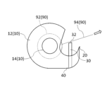
- FIG. 1 is a side view of one embodiment of a tape cutter according to the present invention
- FIG. FIG. 2 is a plan view showing the tape cutter of FIG. 1
- 3 is a plan view for explaining dimensions and the like of the sticking portion 30.
- FIG. 3 is a side view showing a cutting blade 20, a sticking portion 30 and an adhesive tape 90;
- FIG. 3 is a side view for explaining an example of how to use the tape cutter of FIG. 1;
- FIG. 3 is a side view for explaining an example of how to use the tape cutter of FIG. 1;
- FIG. 3 is a plan view for explaining the effect of the tape cutter of FIG. 1; It is a top view for demonstrating the modification of the sticking part 30.
- FIG. It is a side view which shows the modification of the tape cutter of FIG.
- FIG. 10 is a plan view showing an overhanging portion 50 in the tape cutter of FIG. 9;
- the tape cutter 1 is a tape cutter for a wound adhesive tape 90 and is used to pay out and cut the adhesive tape 90 .
- the tape cutter 1 may be of a hand-held type or a desktop type.
- the adhesive tape 90 is wound around an annular core.
- the adhesive tape 90 may be provided with an adhesive surface only on the lower surface, or may be provided with an adhesive surface on both surfaces (upper surface and lower surface). Examples of the former include cellophane tape. Examples of the latter include, for example, double-sided tape.
- the adhesive surface of the double-sided tape may be exposed only on the lower surface, or may be exposed on both surfaces. In the former double-sided tape, a release paper is attached to the upper surface.
- the tape cutter 1 includes a holding portion 10 , a cutting blade 20 , an adhering portion 30 and an arm portion 40 .
- the holding portion 10 rotatably holds the winding portion 92 of the adhesive tape 90 .
- the wound portion 92 is a portion wound around the core of the adhesive tape 90 and has an annular shape as a whole. The lower surface of each portion of the winding portion 92 is adhered to the upper surface or core of the other portion of the winding portion 92 .
- the holding portion 10 has a side plate portion 12 and a shaft portion 14 .
- the side plate portion 12 covers the adhesive tape 90 from the sides.
- the side plate portions 12 may be provided on both sides of the adhesive tape 90, or may be provided on only one side.
- the side plate portion 12 may cover the entire adhesive tape 90 from the side, or may cover only a portion thereof. That is, the side plate portion 12 may overlap the entire adhesive tape 90 or may overlap only a portion of the adhesive tape 90 in a side view.
- the shaft part 14 supports the adhesive tape 90 while being inserted inside the core of the adhesive tape 90 .
- the shaft portion 14 may be fixed to the side plate portion 12 or may be provided rotatably with respect to the side plate portion 12 . In the former case, the adhesive tape 90 rotates independently when it is paid out. In the latter case, the adhesive tape 90 rotates together with the shaft portion 14 when unwound.
- the shaft portion 14 is preferably molded integrally with the side plate portion 12 .
- plastic, metal, wood, or paper can be used as a material of the holding part 10.
- the plastic may be a biodegradable plastic. Papers also include processed papers and cellulose nanofibers (CNF).
- the cutting blade 20 cuts the lead-out portion 94 of the adhesive tape 90 .
- the pull-out portion 94 is a portion of the adhesive tape 90 pulled out from the winding portion 92 . Therefore, the lower surface of the lead-out portion 94 is attached neither to the upper surface of the wound portion 92 nor to the core.
- the cutting blade 20 is arranged apart from the winding portion 92 . Thereby, the cutting blade 20 cuts the lead-out portion 94 leaving a certain length of the lead-out portion 94 . When cutting the lead-out portion 94 , the cutting blade 20 contacts the lower surface of the lead-out portion 94 .
- the material of the cutting blade 20 may be the same as or different from the material of the holding portion 10 .
- the cutting blade 20 may be molded integrally with the holding portion 10 .
- the sticking portion 30 is positioned between the winding portion 92 (holding portion 10 ) and the cutting blade 20 . In this embodiment, the sticking portion 30 is separated from the cutting blade 20 .
- a part of the lead-out portion 94 is attached to the attaching portion 30 . Specifically, a portion of the lower surface of the lead-out portion 94 is attached to the attachment surface 32 of the attachment portion 30 .
- the sticking surface 32 is equal to the upper surface of the sticking portion 30 .
- the sticking surface 32 is planar.
- the portion of the lead-out portion 94 (the portion adhered to the sticking portion 30) is present between the tip 94a and the base 94b of the lead-out portion 94. As shown in FIG.
- the material of the sticking portion 30 may be the same as or different from the material of the holding portion 10 .
- Width w ⁇ b>1 of sticking portion 30 is smaller than width w ⁇ b>2 of adhesive tape 90 . That is, the width w1 is designed to be smaller than the width w2 of the adhesive tape 90 that is assumed to be used in the tape cutter 1 .
- the width w1 is defined as the dimension of the sticking surface 32 in the width direction (the direction perpendicular to the extending direction of the lead-out portion 94).
- the width w1 is preferably 50% or less of the width w2, more preferably 20% or less.
- the width w1 is smaller than the width of the cutting blade 20. As shown in FIG.
- the width w1 is preferably 50% or less of the width of the cutting blade 20, more preferably 20% or less.
- the widthwise dimension of the sticking portion 30 is always smaller than the width w2 in the exposed area. That is, it is preferable that the widthwise dimension of the sticking portion 30 is smaller than the width w2 at any position in the height direction (the vertical direction in FIG. 1) of the sticking portion 30 in the exposed region.
- the exposed region means a region where the sticking portion 30 is exposed (a region that does not overlap with the holding portion 10 or the arm portion 40) in side view.
- the portion of the sticking portion 30 indicated by solid lines is the exposed region.
- the widthwise dimension of the sticking portion 30 may or may not be constant in the exposed area. In the former case, the widthwise dimension of the sticking portion 30 is equal to the width w1 at any position in the height direction of the sticking portion 30 in the exposed region.
- the length d1 of the sticking portion 30 is greater than the width w1.
- the length d1 is defined as the dimension of the sticking surface 32 in the extending direction of the lead-out portion 94. As shown in FIG.
- the length d1 is, for example, 5 mm or more and 15 mm or less.
- the bisecting plane P1 of the sticking portion 30 coincides with the bisecting plane P2 of the cutting blade 20 .
- the bisecting plane P1 is a plane perpendicular to the width direction that bisects the sticking surface 32 .
- the bisecting plane P2 is a plane perpendicular to the width direction that bisects the cutting blade 20 .
- FIG. 4 is a side view showing the cutting blade 20, the sticking portion 30 and the adhesive tape 90.
- FIG. As can be seen from the figure, the sticking surface 32 of the sticking portion 30 is positioned above the reference line L1 (first reference line) in a side view.
- the reference line L1 is a straight line passing through the base 94b of the lead-out portion 94 and the tip of the cutting blade 20 (the tip 94a of the lead-out portion 94).
- a height h1 of the sticking surface 32 from the reference line L1 is preferably 5 mm or more, and more preferably 10 mm or more.
- the height h1 is defined as the length of a perpendicular line drawn from a portion of the attachment surface 32 closest to the reference line L1 (in the case of this embodiment, an end portion 32b described later) to the reference line L1 in a side view. . Further, in a side view, the end portion 32a of the adhering surface 32 on the side of the cutting blade 20 (the side of the tip 94a) is located above the reference line L2 (second reference line).
- the reference line L2 is a straight line passing through the end portion 32b of the sticking surface 32 on the side of the holding portion 10 (the side of the root 94b) and the tip of the cutting blade 20. As shown in FIG.
- the arm part 40 connects the holding part 10 and the cutting blade 20 .
- the arm portion 40 extends from the holding portion 10 to the cutting blade 20 through the lower surface side of the drawer portion 94 .
- a space for inserting a finger exists above the arm portion 40 .
- the material of the arm portion 40 may be the same as or different from that of the holding portion 10 .
- the arm portion 40 is preferably molded integrally with the holding portion 10 .
- the sticking portion 30 is connected to the arm portion 40 . Specifically, the sticking portion 30 is erected on the arm portion 40 .
- the sticking part 30 is fixed so as not to move with respect to the arm part 40 .
- the sticking portion 30 may be molded integrally with the arm portion 40 .
- the pull-out portion 94 is pinched with fingers, and the pull-out portion 94 is peeled off from the cutting blade 20 and the adhering portion 30. Then, the adhesive tape 90 is extended until the pull-out portion 94 reaches a desired length. pull out Next, as shown in FIG. 6, the lead-out portion 94 is cut by pressing the lead-out portion 94 against the tip of the cutting blade 20 . After cutting, the lead-out portion 94 is stuck to the sticking portion 30 again. Further, the leading end 94a of the lead-out portion 94 is stuck to the cutting blade 20 (see FIG. 1).
- the lead-out portion 94 is stuck only to the cutting blade 20 and the sticking portion 30 . That is, the tape cutter 1 is configured so that the pull-out portion 94 is not adhered to a portion of the tape cutter 1 other than the cutting blade 20 or the adhered portion 30 .
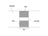
- the width w ⁇ b>1 of the sticking portion 30 is smaller than the width w ⁇ b>2 of the adhesive tape 90 .
- a portion 94c that is not adhered to the adhered portion 30 is located in the same region R1 as the adhered portion 30 with respect to the extension direction of the lead-out portion 94 of the adhesive tape 90 (horizontal direction in FIG. 7). (A portion protruding from the sticking surface 32) exists.
- the portion 94c is hatched.
- the region R1 is a region in contact with the sticking surface 32 in side view. Since both sides of the portion 94c are exposed, it can be picked up with fingers.
- the tape cutter 1 having a structure suitable for miniaturization is realized.
- the length of the lead-out part 94 is shortened, so dust is less likely to adhere to the adhesive tape 90 .
- the lead-out portion 94 is attached to the sticking portion 30, even if the tip 94a of the lead-out portion 94 is separated from the cutting blade 20, the situation in which the lead-out portion 94 returns to the winding portion 92 is less likely to occur. be able to.
- the width w1 of the adhering portion 30 is smaller than the width w2 of the adhesive tape 90, the contact area with the adhesive tape 90 and, in turn, the adhesive force with the adhesive tape 90 can be adjusted by changing the width w1. can be done. This increases options for the material of the sticking portion 30, making it easier to integrally mold the sticking portion 30 with other parts (the holding portion 10, the cutting blade 20, and/or the arm portion 40).
- the width w1 is preferably 50% or less of the width w2, more preferably 20% or less.
- the width w1 is preferably 5% or more of the width w2.
- the widthwise dimension of the sticking portion 30 is always smaller than the width w2 in the exposed area, it is advantageous to ensure a wide space for inserting a finger under the portion 94c.
- the widthwise dimension of the sticking portion 30 is constant in the exposed region, the sticking portion 30 does not enter below the portion 94c in the exposed region, which is particularly advantageous for securing a wide space for inserting a finger. is.
- the sticking part 30 is separated from the cutting blade 20. This makes it difficult for fingers to touch the cutting blade 20 when pinching the portion 94c, so that the safety of the tape cutter 1 can be enhanced.
- the bisecting plane P1 of the sticking portion 30 coincides with the bisecting plane P2 of the cutting blade 20 .
- the lead-out portion 94 is supported substantially evenly in the width direction by the adhering portion 30, so that the cutting can be smoothly performed.
- the length d1 of the sticking portion 30 is greater than the width w1 of the sticking portion 30.
- the sticking surface 32 of the sticking portion 30 When viewed from the side, the sticking surface 32 of the sticking portion 30 is positioned above the reference line L1. In this case, it is possible to pinch the lead portion 94 above the reference line L1. By utilizing the space above the reference line L1 in this way, the distance from the holding part 10 to the cutting blade 20 can be easily shortened. Further, in this case, when the cutting blade 20 cuts the lead-out portion 94 , the sticking surface 32 strongly contacts the lower surface of the lead-out portion 94 .
- a larger height h1 of the adhering surface 32 from the reference line L1 is advantageous in utilizing the space above the reference line L1 and in bringing the adhering surface 32 into strong contact with the lower surface of the drawer portion 94.
- the height h1 is preferably 5 mm or more, more preferably 10 mm or more.
- the height h1 is preferably 30 mm or less.
- the end 32a of the sticking surface 32 is located above the reference line L2. In this case, when cutting the lead-out portion 94 with the cutting blade 20 , the entire sticking surface 32 strongly contacts the lower surface of the lead-out portion 94 .
- the tape cutter 1 is configured so that the pull-out portion 94 is not attached to a portion of the tape cutter 1 other than the cutting blade 20 or the attaching portion 30 .
- both sides of the adhesive tape 90 are exposed in the entire portion of the pull-out portion 94 that is not attached to the cutting blade 20 or the attaching portion 30 . This increases the percentage of the portion that can be picked with the fingers. This is also advantageous for shortening the distance from the holding part 10 to the cutting blade 20 .
- An arm portion 40 is provided on the tape cutter 1 . This makes it possible to realize the tape cutter 1 in which a predetermined distance is maintained between the holding portion 10 and the cutting blade 20 with a simple configuration.
- the manufacturing process of the tape cutter 1 can be simplified, thereby reducing the manufacturing cost of the tape cutter 1.
- the sticking part 30 is connected to the arm part 40 .
- the tape cutter 1 in which the adhering portion 30 is arranged between the winding portion 92 and the cutting blade 20 can be realized with a simple configuration.
- the manufacturing process of the tape cutter 1 can be simplified, thereby reducing the manufacturing cost of the tape cutter 1.
- the tape cutter 1 contains CNF as a material, it is advantageous for reducing the weight and increasing the strength of the tape cutter 1. Moreover, using CNF also contributes to reduction of environmental load.
- the adhesive tape 90 is a double-sided tape with adhesive surfaces exposed on both sides, dust tends to adhere to the upper surface of the drawer portion 94 compared to an adhesive tape with an adhesive surface exposed only on the lower surface. Therefore, the tape cutter 1 that can reduce the length of the lead-out portion 94 is particularly useful.
- the present invention is not limited to the above embodiments, and various modifications are possible.
- the case where the adhering portion 30 is separated from the cutting blade 20 is exemplified.
- the sticking portion 30 may be adjacent to the cutting blade 20 . In that case, it becomes easier to form the sticking portion 30 integrally with the cutting blade 20 .
- the bisecting plane P1 of the sticking portion 30 coincides with the bisecting plane P2 of the cutting blade 20 as an example.
- the bisecting plane P1 does not have to coincide with the bisecting plane P2, for example as shown in FIG.
- a portion 94c that is not stuck to the sticking portion 30 can be secured widely on one side of the sticking portion 30 (upper side in FIG. 8). . This makes it easier to pick up the portion 94c with fingers.
- length d1 of the sticking portion 30 is greater than the width w1 of the sticking portion 30 is exemplified.
- length d1 may be equal to width w1 or may be less than width w1.
- the sticking surface 32 of the sticking portion 30 is positioned above the reference line L1 in side view is exemplified.
- the sticking surface 32 may be positioned on the reference line L1 or may be positioned below the reference line L1.
- the lead-out portion 94 can be reliably attached to the attachment surface 32 by pressing the lead-out portion 94 against the attachment surface 32 from above with a finger.
- the case where the end 32a of the sticking surface 32 is located above the reference line L2 in side view is illustrated.
- the end portion 32a may be positioned on the reference line L2 or may be positioned below the reference line L2.
- the lead-out portion 94 can be reliably attached to the entire attachment surface 32 by pressing the lead-out portion 94 against the sticking surface 32 from above with a finger.
- the tape cutter 1 may be provided with an overhang portion 50 as shown in FIGS. 9 and 10, for example.
- FIG. 10 is a top view of the projecting portion 50 of FIG.
- the overhanging portion 50 overhangs the drawer portion 94 from the holding portion 10 .
- the projecting portion 50 extends above the sticking portion 30 . That is, the projecting portion 50 overlaps the sticking portion 30 in plan view.
- the projecting portion 50 overlaps the entire sticking portion 30 in plan view.
- the projecting portion 50 extends above the cutting blade 20 . That is, the projecting portion 50 overlaps the cutting blade 20 in plan view.
- the protruding portion 50 does not have to reach above the cutting blade 20 and does not have to reach above the sticking portion 30 .
- the protruding portion 50 By providing the protruding portion 50 in this manner, the effect of suppressing dust from adhering to the drawer portion 94 can be obtained.
- the projecting portion 50 extends above the sticking portion 30 , the above effect can be exerted over a wide range of the drawing portion 94 .
- the protruding portion 50 extends above the cutting blade 20 , the above effect can be exerted on substantially the entire drawn portion 94 .
Landscapes
- Adhesive Tape Dispensing Devices (AREA)
Abstract
The present invention provides a tape cutter having a structure suitable for reducing the size thereof. A tape cutter 1 is for an adhesive tape 90 wound thereon, and includes a holding part 10, a cutting blade 20, and an adhesive part 30. The holding part 10 rotatably holds a wound part 92 of the adhesive tape 90. The cutting blade 20 cuts a drawn-out part 94 that is a section of the adhesive tape 90 drawn out from the wound part 92. The adhesive part 30 is positioned between the wound part 92 and the cutting blade 20. A portion of the drawn-out part 94 is adhered to the adhesive part 30. The width of the adhesive part 30 is smaller than the width of the adhesive tape 90.
Description
本発明は、粘着テープ用のテープカッターに関する。
The present invention relates to a tape cutter for adhesive tape.
従来のテープカッターとしては、例えば特許文献1に記載されたものがある。同文献に記載されたテープカッターは、粘着テープを巻芯に巻回してなるテープロールを回転自在に保持する保持部、テープロールから引き出された粘着テープの先端部が貼着される貼着部(仮留め部)、及び粘着テープを切断するための切断刃を備えている。貼着部は、保持部と切断刃との間に設けられている。
As a conventional tape cutter, there is one described in Patent Document 1, for example. The tape cutter described in the same document includes a holding part that rotatably holds a tape roll formed by winding an adhesive tape around a core, and a sticking part that sticks the leading end of the adhesive tape pulled out from the tape roll. (temporary fastening portion) and a cutting blade for cutting the adhesive tape. The sticking portion is provided between the holding portion and the cutting blade.
上述のテープカッターにおいては、粘着テープを指で摘んで先端側に引っ張ることにより、粘着テープが繰り出される。このように粘着テープを指で摘めるようにするには、保持部と貼着部との間に指を入れるのに充分なスペースを確保する必要がある。そのため、保持部から切断刃までの距離を長くせざるを得ない。このことは、従来のテープカッターの小型化を妨げる要因となっていた。
In the tape cutter described above, the adhesive tape is fed out by pinching the adhesive tape with fingers and pulling it toward the tip side. In order to be able to pick up the adhesive tape with fingers in this way, it is necessary to secure a sufficient space between the holding portion and the sticking portion for inserting the fingers. Therefore, the distance from the holding portion to the cutting blade must be increased. This has been a factor hindering the miniaturization of conventional tape cutters.
本発明は、上記課題に鑑みてなされたものであり、小型化に適した構造のテープカッターを提供することを目的とする。
The present invention has been made in view of the above problems, and an object of the present invention is to provide a tape cutter having a structure suitable for miniaturization.
本発明によるテープカッターは、巻回された粘着テープ用のテープカッターであって、上記粘着テープの巻回部を回転可能に保持する保持部と、上記粘着テープにおける上記巻回部から引き出された部分である引出部を切断する切断刃と、上記巻回部と上記切断刃との間に位置し、上記粘着テープの上記引出部の一部が貼着される貼着部と、を備え、上記貼着部の幅は、上記粘着テープの幅よりも小さいことを特徴とする。
A tape cutter according to the present invention is a tape cutter for a wound adhesive tape, and includes a holding portion that rotatably holds the wound portion of the adhesive tape, and a holding portion that is pulled out from the wound portion of the adhesive tape a cutting blade that cuts the lead-out portion, which is a part, and an adhering portion that is positioned between the winding portion and the cutting blade and to which a part of the lead-out portion of the adhesive tape is affixed, The width of the sticking portion is smaller than the width of the adhesive tape.
このテープカッターにおいては、貼着部の幅が粘着テープの幅よりも小さい。この場合、粘着テープの引出部の延在方向について貼着部と同一の領域に、貼着部に貼着されない部分が存在する。当該部分は、両面が露出しているため、指で摘むことが可能である。このため、上記領域においても、引出部を指で摘むことが可能となる。これにより、保持部から切断刃までの距離を短くしても、粘着テープの引出部を指で摘むことができる。
In this tape cutter, the width of the sticking part is smaller than the width of the adhesive tape. In this case, there is a portion not adhered to the adhered portion in the same region as the adhered portion in the extending direction of the lead-out portion of the adhesive tape. Since both sides of the portion are exposed, it is possible to pick it up with fingers. Therefore, it is possible to pick up the drawer portion with fingers even in the above region. Thereby, even if the distance from the holding part to the cutting blade is shortened, the pulled-out part of the adhesive tape can be picked up with fingers.
本発明によれば、小型化に適した構造のテープカッターが実現される。
According to the present invention, a tape cutter with a structure suitable for miniaturization is realized.
以下、図面を参照しつつ、本発明の実施形態について詳細に説明する。なお、図面の説明においては、同一要素には同一符号を付し、重複する説明を省略する。
Hereinafter, embodiments of the present invention will be described in detail with reference to the drawings. In the description of the drawings, the same elements are denoted by the same reference numerals, and overlapping descriptions are omitted.
図1及び図2は、それぞれ、本発明によるテープカッターの一実施形態を示す側面図及び平面図である。テープカッター1は、巻回された粘着テープ90用のテープカッターであって、粘着テープ90を繰り出して切断するのに用いられる。テープカッター1は、手に持って使用するタイプであってもよいし、卓上で使用するタイプであってもよい。粘着テープ90は、円環状の芯に巻回されている。粘着テープ90は、下面にのみ粘着面が設けられていてもよいし、両面(上面及び下面)に粘着面が設けられていてもよい。前者の例としては、例えばセロハンテープが挙げられる。後者の例としては、例えば両面テープが挙げられる。両面テープは、下面にのみ粘着面が露出していてもよいし、両面に粘着面が露出していてもよい。前者の両面テープにおいては、上面に剥離紙が貼着されている。
1 and 2 are side and plan views, respectively, of an embodiment of a tape cutter according to the present invention. The tape cutter 1 is a tape cutter for a wound adhesive tape 90 and is used to pay out and cut the adhesive tape 90 . The tape cutter 1 may be of a hand-held type or a desktop type. The adhesive tape 90 is wound around an annular core. The adhesive tape 90 may be provided with an adhesive surface only on the lower surface, or may be provided with an adhesive surface on both surfaces (upper surface and lower surface). Examples of the former include cellophane tape. Examples of the latter include, for example, double-sided tape. The adhesive surface of the double-sided tape may be exposed only on the lower surface, or may be exposed on both surfaces. In the former double-sided tape, a release paper is attached to the upper surface.
テープカッター1は、保持部10、切断刃20、貼着部30、及び腕部40を備えている。保持部10は、粘着テープ90の巻回部92を回転可能に保持する。巻回部92は、粘着テープ90における芯に巻回された部分であり、全体として円環状をしている。巻回部92の各部分の下面は、巻回部92の他の部分の上面、又は芯に貼着されている。保持部10は、側板部12、及び軸部14を有している。側板部12は、粘着テープ90を側方から覆っている。側板部12は、粘着テープ90の両側に設けられていてもよいし、片側にのみ設けられていてもよい。また、側板部12は、側方から粘着テープ90の全体を覆っていてもよいし、一部のみを覆っていてもよい。すなわち、側板部12は、側面視で、粘着テープ90の全体に重なっていてもよいし、一部にのみ重なっていてもよい。
The tape cutter 1 includes a holding portion 10 , a cutting blade 20 , an adhering portion 30 and an arm portion 40 . The holding portion 10 rotatably holds the winding portion 92 of the adhesive tape 90 . The wound portion 92 is a portion wound around the core of the adhesive tape 90 and has an annular shape as a whole. The lower surface of each portion of the winding portion 92 is adhered to the upper surface or core of the other portion of the winding portion 92 . The holding portion 10 has a side plate portion 12 and a shaft portion 14 . The side plate portion 12 covers the adhesive tape 90 from the sides. The side plate portions 12 may be provided on both sides of the adhesive tape 90, or may be provided on only one side. Also, the side plate portion 12 may cover the entire adhesive tape 90 from the side, or may cover only a portion thereof. That is, the side plate portion 12 may overlap the entire adhesive tape 90 or may overlap only a portion of the adhesive tape 90 in a side view.
軸部14は、粘着テープ90の芯の内側に挿通された状態で、粘着テープ90を支持する。軸部14は、側板部12に固定されていてもよいし、側板部12に対して回転可能に設けられていてもよい。前者の場合、粘着テープ90は、繰り出される際に単独で回転する。後者の場合、粘着テープ90は、繰り出される際に軸部14と共に回転する。軸部14が側板部12に固定される場合、軸部14は、側板部12と一体に成形されることが好ましい。保持部10の材料としては、例えば、プラスチック、金属、木材、又は紙類を用いることができる。プラスチックは、生分解性プラスチックであってもよい。紙類には、加工紙、及びセルロースナノファイバー(CNF)も含まれる。
The shaft part 14 supports the adhesive tape 90 while being inserted inside the core of the adhesive tape 90 . The shaft portion 14 may be fixed to the side plate portion 12 or may be provided rotatably with respect to the side plate portion 12 . In the former case, the adhesive tape 90 rotates independently when it is paid out. In the latter case, the adhesive tape 90 rotates together with the shaft portion 14 when unwound. When the shaft portion 14 is fixed to the side plate portion 12 , the shaft portion 14 is preferably molded integrally with the side plate portion 12 . As a material of the holding part 10, for example, plastic, metal, wood, or paper can be used. The plastic may be a biodegradable plastic. Papers also include processed papers and cellulose nanofibers (CNF).
切断刃20は、粘着テープ90の引出部94を切断する。引出部94は、粘着テープ90における巻回部92から引き出された部分である。それゆえ、引出部94の下面は、巻回部92の上面にも芯にも貼着されていない。切断刃20は、巻回部92から離間して配置されている。これにより、切断刃20は、一定の長さの引出部94を残して、引出部94を切断する。引出部94を切断する際、切断刃20は、引出部94の下面に当接する。切断刃20の材料は、保持部10の材料と同一であってもよいし、異なっていてもよい。切断刃20は、保持部10と一体に成形されてもよい。
The cutting blade 20 cuts the lead-out portion 94 of the adhesive tape 90 . The pull-out portion 94 is a portion of the adhesive tape 90 pulled out from the winding portion 92 . Therefore, the lower surface of the lead-out portion 94 is attached neither to the upper surface of the wound portion 92 nor to the core. The cutting blade 20 is arranged apart from the winding portion 92 . Thereby, the cutting blade 20 cuts the lead-out portion 94 leaving a certain length of the lead-out portion 94 . When cutting the lead-out portion 94 , the cutting blade 20 contacts the lower surface of the lead-out portion 94 . The material of the cutting blade 20 may be the same as or different from the material of the holding portion 10 . The cutting blade 20 may be molded integrally with the holding portion 10 .
貼着部30は、巻回部92(保持部10)と切断刃20との間に位置する。本実施形態において貼着部30は、切断刃20から離間している。貼着部30には、引出部94の一部が貼着される。具体的には、貼着部30の貼着面32に、引出部94の下面の一部が貼着される。貼着面32は、貼着部30の上面に等しい。貼着面32は、平面状をしている。引出部94の上記一部(貼着部30に貼着される部分)は、引出部94の先端94aと根元94bとの間に存在する。貼着部30の材料は、保持部10の材料と同一であってもよいし、異なっていてもよい。
The sticking portion 30 is positioned between the winding portion 92 (holding portion 10 ) and the cutting blade 20 . In this embodiment, the sticking portion 30 is separated from the cutting blade 20 . A part of the lead-out portion 94 is attached to the attaching portion 30 . Specifically, a portion of the lower surface of the lead-out portion 94 is attached to the attachment surface 32 of the attachment portion 30 . The sticking surface 32 is equal to the upper surface of the sticking portion 30 . The sticking surface 32 is planar. The portion of the lead-out portion 94 (the portion adhered to the sticking portion 30) is present between the tip 94a and the base 94b of the lead-out portion 94. As shown in FIG. The material of the sticking portion 30 may be the same as or different from the material of the holding portion 10 .
図3を参照しつつ、貼着部30の寸法等について説明する。同図は、切断刃20、貼着部30及び引出部94を、貼着面32に垂直な方向から見た図である。貼着部30の幅w1は、粘着テープ90の幅w2よりも小さい。すなわち、幅w1は、テープカッター1において使用することが想定される粘着テープ90の幅w2よりも小さく設計されている。幅w1は、貼着面32の幅方向(引出部94の延在方向に垂直な方向)の寸法として定義される。幅w1は、幅w2の50%以下であることが好ましく、20%以下であることがより好ましい。当然、幅w1は、切断刃20の幅よりも小さい。幅w1は、切断刃20の幅の50%以下であることが好ましく、20%以下であることがより好ましい。
The dimensions and the like of the sticking portion 30 will be described with reference to FIG. This figure is a view of the cutting blade 20 , the sticking portion 30 and the lead-out portion 94 viewed from a direction perpendicular to the sticking surface 32 . Width w<b>1 of sticking portion 30 is smaller than width w<b>2 of adhesive tape 90 . That is, the width w1 is designed to be smaller than the width w2 of the adhesive tape 90 that is assumed to be used in the tape cutter 1 . The width w1 is defined as the dimension of the sticking surface 32 in the width direction (the direction perpendicular to the extending direction of the lead-out portion 94). The width w1 is preferably 50% or less of the width w2, more preferably 20% or less. Naturally, the width w1 is smaller than the width of the cutting blade 20. As shown in FIG. The width w1 is preferably 50% or less of the width of the cutting blade 20, more preferably 20% or less.
貼着部30の幅方向の寸法は、露出領域で、常に幅w2よりも小さいことが好ましい。すなわち、露出領域内では、貼着部30の高さ方向(図1の上下方向)の何れの位置においても、貼着部30の幅方向の寸法が幅w2よりも小さいことが好ましい。ここで、露出領域とは、側面視で、貼着部30が露出する領域(保持部10又は腕部40に重ならない領域)をいう。図1において、貼着部30のうち実線で表されている部分が、露出領域である。貼着部30の幅方向の寸法は、露出領域で、一定であってもよいし、一定でなくてもよい。前者の場合、露出領域内では、貼着部30の高さ方向の何れの位置においても、貼着部30の幅方向の寸法が幅w1に等しいということである。
It is preferable that the widthwise dimension of the sticking portion 30 is always smaller than the width w2 in the exposed area. That is, it is preferable that the widthwise dimension of the sticking portion 30 is smaller than the width w2 at any position in the height direction (the vertical direction in FIG. 1) of the sticking portion 30 in the exposed region. Here, the exposed region means a region where the sticking portion 30 is exposed (a region that does not overlap with the holding portion 10 or the arm portion 40) in side view. In FIG. 1, the portion of the sticking portion 30 indicated by solid lines is the exposed region. The widthwise dimension of the sticking portion 30 may or may not be constant in the exposed area. In the former case, the widthwise dimension of the sticking portion 30 is equal to the width w1 at any position in the height direction of the sticking portion 30 in the exposed region.
貼着部30の長さd1は、幅w1よりも大きい。長さd1は、引出部94の延在方向についての貼着面32の寸法として定義される。長さd1は、例えば、5mm以上15mm以下である。本実施形態において貼着部30の二等分平面P1は、切断刃20の二等分平面P2に一致している。二等分平面P1は、貼着面32を二等分する幅方向に垂直な平面である。二等分平面P2は、切断刃20を二等分する幅方向に垂直な平面である。
The length d1 of the sticking portion 30 is greater than the width w1. The length d1 is defined as the dimension of the sticking surface 32 in the extending direction of the lead-out portion 94. As shown in FIG. The length d1 is, for example, 5 mm or more and 15 mm or less. In this embodiment, the bisecting plane P1 of the sticking portion 30 coincides with the bisecting plane P2 of the cutting blade 20 . The bisecting plane P1 is a plane perpendicular to the width direction that bisects the sticking surface 32 . The bisecting plane P2 is a plane perpendicular to the width direction that bisects the cutting blade 20 .
図4は、切断刃20、貼着部30及び粘着テープ90を示す側面図である。同図からわかるように、側面視で、貼着部30の貼着面32は、基準線L1(第1基準線)の上方に位置している。基準線L1は、引出部94の根元94bと切断刃20の先端(引出部94の先端94a)とを通る直線である。基準線L1からの貼着面32の高さh1は、5mm以上であることが好ましく、10mm以上であることがより好ましい。高さh1は、側面視で、貼着面32のうち基準線L1に最も近い部分(本実施形態の場合、後述する端部32b)から基準線L1に下した垂線の長さとして定義される。また、側面視で、貼着面32の切断刃20側(先端94a側)の端部32aは、基準線L2(第2基準線)の上方に位置している。基準線L2は、貼着面32の保持部10側(根元94b側)の端部32bと切断刃20の先端とを通る直線である。
4 is a side view showing the cutting blade 20, the sticking portion 30 and the adhesive tape 90. FIG. As can be seen from the figure, the sticking surface 32 of the sticking portion 30 is positioned above the reference line L1 (first reference line) in a side view. The reference line L1 is a straight line passing through the base 94b of the lead-out portion 94 and the tip of the cutting blade 20 (the tip 94a of the lead-out portion 94). A height h1 of the sticking surface 32 from the reference line L1 is preferably 5 mm or more, and more preferably 10 mm or more. The height h1 is defined as the length of a perpendicular line drawn from a portion of the attachment surface 32 closest to the reference line L1 (in the case of this embodiment, an end portion 32b described later) to the reference line L1 in a side view. . Further, in a side view, the end portion 32a of the adhering surface 32 on the side of the cutting blade 20 (the side of the tip 94a) is located above the reference line L2 (second reference line). The reference line L2 is a straight line passing through the end portion 32b of the sticking surface 32 on the side of the holding portion 10 (the side of the root 94b) and the tip of the cutting blade 20. As shown in FIG.
図1に戻って、腕部40は、保持部10と切断刃20とを連結している。腕部40は、引出部94の下面側を通って、保持部10から切断刃20まで延びている。腕部40の上方には、指を入れるスペースが存在する。腕部40の材料は、保持部10の材料と同一であってもよいし、異なっていてもよい。前者の場合、腕部40は、保持部10と一体に成形されることが好ましい。貼着部30は、腕部40に接続されている。詳細には、貼着部30は、腕部40に立設されている。貼着部30は、腕部40に対して動かないように固定されている。貼着部30は、腕部40と一体に成形されてもよい。
Returning to FIG. 1, the arm part 40 connects the holding part 10 and the cutting blade 20 . The arm portion 40 extends from the holding portion 10 to the cutting blade 20 through the lower surface side of the drawer portion 94 . A space for inserting a finger exists above the arm portion 40 . The material of the arm portion 40 may be the same as or different from that of the holding portion 10 . In the former case, the arm portion 40 is preferably molded integrally with the holding portion 10 . The sticking portion 30 is connected to the arm portion 40 . Specifically, the sticking portion 30 is erected on the arm portion 40 . The sticking part 30 is fixed so as not to move with respect to the arm part 40 . The sticking portion 30 may be molded integrally with the arm portion 40 .
図5及び図6を参照しつつ、テープカッター1の使用方法の一例を説明する。まず、図5に示すように、引出部94を指で摘んで、引出部94を切断刃20及び貼着部30から剥がした後、引出部94が所望の長さになるまで粘着テープ90を引き出す。次に、図6に示すように、引出部94を切断刃20の先端に押し当てるようにして引出部94を切断する。切断後、引出部94は、再び、貼着部30に貼着された状態となる。また、引出部94の先端94aは、切断刃20に貼着された状態となる(図1参照)。このとき、引出部94は、切断刃20及び貼着部30にのみ貼着されている。すなわち、テープカッター1は、テープカッター1における切断刃20又は貼着部30以外の部分に引出部94が貼着されないように構成されている。
An example of how to use the tape cutter 1 will be described with reference to FIGS. First, as shown in FIG. 5, the pull-out portion 94 is pinched with fingers, and the pull-out portion 94 is peeled off from the cutting blade 20 and the adhering portion 30. Then, the adhesive tape 90 is extended until the pull-out portion 94 reaches a desired length. pull out Next, as shown in FIG. 6, the lead-out portion 94 is cut by pressing the lead-out portion 94 against the tip of the cutting blade 20 . After cutting, the lead-out portion 94 is stuck to the sticking portion 30 again. Further, the leading end 94a of the lead-out portion 94 is stuck to the cutting blade 20 (see FIG. 1). At this time, the lead-out portion 94 is stuck only to the cutting blade 20 and the sticking portion 30 . That is, the tape cutter 1 is configured so that the pull-out portion 94 is not adhered to a portion of the tape cutter 1 other than the cutting blade 20 or the adhered portion 30 .
テープカッター1の効果を説明する。テープカッター1においては、貼着部30の幅w1が粘着テープ90の幅w2よりも小さい。この場合、図7に示すように、粘着テープ90の引出部94の延在方向(同図の左右方向)について貼着部30と同一の領域R1に、貼着部30に貼着されない部分94c(貼着面32から食み出す部分)が存在する。同図においては、部分94cに斜線が付されている。領域R1は、側面視で貼着面32に接している領域である。部分94cは、両面が露出しているため、指で摘むことが可能である。このため、領域R1においても、引出部94を指で摘むことが可能となる。これにより、保持部10から切断刃20までの距離を短くしても、粘着テープ90の引出部94を指で摘むことができる。したがって、小型化に適した構造のテープカッター1が実現されている。
Explain the effects of Tape Cutter 1. In the tape cutter 1 , the width w<b>1 of the sticking portion 30 is smaller than the width w<b>2 of the adhesive tape 90 . In this case, as shown in FIG. 7, a portion 94c that is not adhered to the adhered portion 30 is located in the same region R1 as the adhered portion 30 with respect to the extension direction of the lead-out portion 94 of the adhesive tape 90 (horizontal direction in FIG. 7). (A portion protruding from the sticking surface 32) exists. In the figure, the portion 94c is hatched. The region R1 is a region in contact with the sticking surface 32 in side view. Since both sides of the portion 94c are exposed, it can be picked up with fingers. Therefore, it is possible to pick up the lead portion 94 with fingers even in the region R1. Thereby, even if the distance from the holding part 10 to the cutting blade 20 is shortened, the pulled-out part 94 of the adhesive tape 90 can be pinched with fingers. Therefore, the tape cutter 1 having a structure suitable for miniaturization is realized.
このように保持部10から切断刃20までの距離を短くした場合、引出部94の長さが小さくなるため、粘着テープ90に塵埃が付着しにくくなる。また、引出部94が貼着部30に貼着されるため、引出部94の先端94aが切断刃20から離れたとしても、引出部94が巻回部92に戻ってしまう事態を起こりにくくすることができる。さらに、貼着部30の幅w1が粘着テープ90の幅w2よりも小さい場合、幅w1を変えることにより、粘着テープ90との接触面積、ひいては粘着テープ90との間の粘着力を調整することができる。これにより、貼着部30の材料の選択肢が増えるため、貼着部30を他の部分(保持部10、切断刃20、及び/又は腕部40)と一体に成形しやすくなる。
When the distance from the holding part 10 to the cutting blade 20 is shortened in this way, the length of the lead-out part 94 is shortened, so dust is less likely to adhere to the adhesive tape 90 . Further, since the lead-out portion 94 is attached to the sticking portion 30, even if the tip 94a of the lead-out portion 94 is separated from the cutting blade 20, the situation in which the lead-out portion 94 returns to the winding portion 92 is less likely to occur. be able to. Furthermore, when the width w1 of the adhering portion 30 is smaller than the width w2 of the adhesive tape 90, the contact area with the adhesive tape 90 and, in turn, the adhesive force with the adhesive tape 90 can be adjusted by changing the width w1. can be done. This increases options for the material of the sticking portion 30, making it easier to integrally mold the sticking portion 30 with other parts (the holding portion 10, the cutting blade 20, and/or the arm portion 40).
幅w1を小さくした方が、貼着部30に貼着されない部分94cが広くなるため、部分94cを指で摘みやすくなる。かかる観点から、幅w1は、幅w2の50%以下であることが好ましく、20%以下であることがより好ましい。他方、幅w1が小さすぎると、貼着部30と粘着テープ90との間の粘着力が不充分になりかねない。かかる観点から、幅w1は、幅w2の5%以上であることが好ましい。
The smaller the width w1, the wider the portion 94c that is not attached to the sticking portion 30, making it easier to pick up the portion 94c with fingers. From this point of view, the width w1 is preferably 50% or less of the width w2, more preferably 20% or less. On the other hand, if the width w1 is too small, the adhesive force between the sticking portion 30 and the adhesive tape 90 may become insufficient. From this point of view, the width w1 is preferably 5% or more of the width w2.
貼着部30の幅方向の寸法が露出領域で常に幅w2よりも小さい場合、部分94cの下方に指を入れるスペースを広く確保するのに有利である。貼着部30の幅方向の寸法が露出領域で一定である場合、露出領域内では、部分94cの下方に貼着部30が全く入り込まないため、指を入れるスペースを広く確保するのに特に有利である。
If the widthwise dimension of the sticking portion 30 is always smaller than the width w2 in the exposed area, it is advantageous to ensure a wide space for inserting a finger under the portion 94c. When the widthwise dimension of the sticking portion 30 is constant in the exposed region, the sticking portion 30 does not enter below the portion 94c in the exposed region, which is particularly advantageous for securing a wide space for inserting a finger. is.
貼着部30は、切断刃20から離間している。これにより、部分94cを摘む際に指が切断刃20に触れにくくなるため、テープカッター1の安全性を高めることができる。
The sticking part 30 is separated from the cutting blade 20. This makes it difficult for fingers to touch the cutting blade 20 when pinching the portion 94c, so that the safety of the tape cutter 1 can be enhanced.
貼着部30の二等分平面P1は、切断刃20の二等分平面P2に一致している。この場合、切断刃20で引出部94を切断する際、引出部94が貼着部30によって幅方向に略均等に支持されるため、切断を円滑に行いやすくなる。
The bisecting plane P1 of the sticking portion 30 coincides with the bisecting plane P2 of the cutting blade 20 . In this case, when cutting the lead-out portion 94 with the cutting blade 20, the lead-out portion 94 is supported substantially evenly in the width direction by the adhering portion 30, so that the cutting can be smoothly performed.
貼着部30の長さd1は、貼着部30の幅w1よりも大きい。このように長さd1を大きくすることにより、引出部94が貼着部30に貼着された状態を安定的に維持しやすくなる。
The length d1 of the sticking portion 30 is greater than the width w1 of the sticking portion 30. By increasing the length d1 in this way, it becomes easier to stably maintain the state in which the lead-out portion 94 is stuck to the sticking portion 30 .
側面視で、貼着部30の貼着面32は、基準線L1の上方に位置している。この場合、基準線L1の上方で引出部94を摘むことが可能になる。このように基準線L1の上方のスペースを活かすことにより、保持部10から切断刃20までの距離を短くしやすくなる。また、この場合、切断刃20で引出部94を切断する際、貼着面32が引出部94の下面に強く接触するため、引出部94を貼着面32に貼着させやすくなる。
When viewed from the side, the sticking surface 32 of the sticking portion 30 is positioned above the reference line L1. In this case, it is possible to pinch the lead portion 94 above the reference line L1. By utilizing the space above the reference line L1 in this way, the distance from the holding part 10 to the cutting blade 20 can be easily shortened. Further, in this case, when the cutting blade 20 cuts the lead-out portion 94 , the sticking surface 32 strongly contacts the lower surface of the lead-out portion 94 .
基準線L1からの貼着面32の高さh1が大きい方が、基準線L1の上方のスペースを活かすのにも、貼着面32を引出部94の下面に強く接触させるのにも有利である。かかる観点から、高さh1は、5mm以上であることが好ましく、10mm以上であることがより好ましい。他方、高さh1が大きすぎると、引出部94の切断に支障を来しかねない。かかる観点から、高さh1は、30mm以下であることが好ましい。
A larger height h1 of the adhering surface 32 from the reference line L1 is advantageous in utilizing the space above the reference line L1 and in bringing the adhering surface 32 into strong contact with the lower surface of the drawer portion 94. be. From this point of view, the height h1 is preferably 5 mm or more, more preferably 10 mm or more. On the other hand, if the height h1 is too large, cutting of the lead-out portion 94 may be hindered. From this point of view, the height h1 is preferably 30 mm or less.
側面視で、貼着面32の端部32aは、基準線L2の上方に位置している。この場合、切断刃20で引出部94を切断する際、貼着面32の全体が引出部94の下面に強く接触するため、引出部94を貼着面32の全体に貼着させやすくなる。
As viewed from the side, the end 32a of the sticking surface 32 is located above the reference line L2. In this case, when cutting the lead-out portion 94 with the cutting blade 20 , the entire sticking surface 32 strongly contacts the lower surface of the lead-out portion 94 .
テープカッター1は、テープカッター1における切断刃20又は貼着部30以外の部分に引出部94が貼着されないように構成されている。この場合、引出部94のうち切断刃20にも貼着部30にも貼着されていない部分の全体において、粘着テープ90の両面が露出することになる。これにより、指で摘める部分の割合が大きくなる。このことも、保持部10から切断刃20までの距離を短くするのに有利である。
The tape cutter 1 is configured so that the pull-out portion 94 is not attached to a portion of the tape cutter 1 other than the cutting blade 20 or the attaching portion 30 . In this case, both sides of the adhesive tape 90 are exposed in the entire portion of the pull-out portion 94 that is not attached to the cutting blade 20 or the attaching portion 30 . This increases the percentage of the portion that can be picked with the fingers. This is also advantageous for shortening the distance from the holding part 10 to the cutting blade 20 .
テープカッター1には、腕部40が設けられている。これにより、簡易な構成で、保持部10と切断刃20との間に所定の間隔が保たれたテープカッター1を実現することができる。
An arm portion 40 is provided on the tape cutter 1 . This makes it possible to realize the tape cutter 1 in which a predetermined distance is maintained between the holding portion 10 and the cutting blade 20 with a simple configuration.
腕部40が保持部10と一体に成形される場合、テープカッター1の製造工程を簡略化し、それによりテープカッター1の製造コストを削減することができる。
When the arm portion 40 is formed integrally with the holding portion 10, the manufacturing process of the tape cutter 1 can be simplified, thereby reducing the manufacturing cost of the tape cutter 1.
貼着部30は、腕部40に接続されている。これにより、簡易な構成で、巻回部92と切断刃20との間に貼着部30が配置されたテープカッター1を実現することができる。
The sticking part 30 is connected to the arm part 40 . As a result, the tape cutter 1 in which the adhering portion 30 is arranged between the winding portion 92 and the cutting blade 20 can be realized with a simple configuration.
貼着部30が腕部40と一体に成形される場合、テープカッター1の製造工程を簡略化し、それによりテープカッター1の製造コストを削減することができる。
When the sticking portion 30 is formed integrally with the arm portion 40, the manufacturing process of the tape cutter 1 can be simplified, thereby reducing the manufacturing cost of the tape cutter 1.
テープカッター1がCNFを材料として含有する場合、テープカッター1の軽量化及び高強度化を図るのに有利となる。また、CNFを用いることは、環境負荷の低減にも資する。
When the tape cutter 1 contains CNF as a material, it is advantageous for reducing the weight and increasing the strength of the tape cutter 1. Moreover, using CNF also contributes to reduction of environmental load.
粘着テープ90が両面に粘着面が露出した両面テープである場合、下面にのみ粘着面が露出した粘着テープに比して、引出部94の上面に塵埃が付着しやすい。それゆえ、引出部94の長さを小さくすることのできるテープカッター1が特に有用となる。
When the adhesive tape 90 is a double-sided tape with adhesive surfaces exposed on both sides, dust tends to adhere to the upper surface of the drawer portion 94 compared to an adhesive tape with an adhesive surface exposed only on the lower surface. Therefore, the tape cutter 1 that can reduce the length of the lead-out portion 94 is particularly useful.
本発明は、上記実施形態に限定されるものではなく、様々な変形が可能である。上記実施形態においては、貼着部30が切断刃20から離間している場合を例示した。しかし、貼着部30は、切断刃20に隣接していてもよい。その場合、貼着部30を切断刃20と一体に成形しやすくなる。
The present invention is not limited to the above embodiments, and various modifications are possible. In the above-described embodiment, the case where the adhering portion 30 is separated from the cutting blade 20 is exemplified. However, the sticking portion 30 may be adjacent to the cutting blade 20 . In that case, it becomes easier to form the sticking portion 30 integrally with the cutting blade 20 .
上記実施形態においては、貼着部30の二等分平面P1が切断刃20の二等分平面P2に一致する場合を例示した。しかし、二等分平面P1は、例えば図8に示すように、二等分平面P2に一致しなくてもよい。この場合、引出部94に対して貼着部30が幅方向に偏るため、貼着部30に貼着されない部分94cを貼着部30の片側(図8の上側)に広く確保することができる。これにより、部分94cを指で摘みやすくなる。
In the above embodiment, the bisecting plane P1 of the sticking portion 30 coincides with the bisecting plane P2 of the cutting blade 20 as an example. However, the bisecting plane P1 does not have to coincide with the bisecting plane P2, for example as shown in FIG. In this case, since the sticking portion 30 is biased in the width direction with respect to the drawer portion 94, a portion 94c that is not stuck to the sticking portion 30 can be secured widely on one side of the sticking portion 30 (upper side in FIG. 8). . This makes it easier to pick up the portion 94c with fingers.
上記実施形態においては、貼着部30の長さd1が貼着部30の幅w1よりも大きい場合を例示した。しかし、長さd1は、幅w1に等しくてもよいし、幅w1より小さくてもよい。
In the above embodiment, the case where the length d1 of the sticking portion 30 is greater than the width w1 of the sticking portion 30 is exemplified. However, length d1 may be equal to width w1 or may be less than width w1.
上記実施形態においては、側面視で貼着部30の貼着面32が基準線L1の上方に位置する場合を例示した。しかし、貼着面32は、基準線L1上に位置してもよいし、基準線L1の下方に位置してもよい。その場合、引出部94の切断後に、引出部94を貼着面32に指で上から押し付けることにより、引出部94を貼着面32に確実に貼着させることができる。
In the above embodiment, the case where the sticking surface 32 of the sticking portion 30 is positioned above the reference line L1 in side view is exemplified. However, the sticking surface 32 may be positioned on the reference line L1 or may be positioned below the reference line L1. In this case, after the lead-out portion 94 is cut, the lead-out portion 94 can be reliably attached to the attachment surface 32 by pressing the lead-out portion 94 against the attachment surface 32 from above with a finger.
上記実施形態においては、側面視で貼着面32の端部32aが基準線L2の上方に位置する場合を例示した。しかし、端部32aは、基準線L2上に位置してもよいし、基準線L2の下方に位置してもよい。その場合、引出部94の切断後に、引出部94を貼着面32に指で上から押し付けることにより、引出部94を貼着面32の全体に確実に貼着させることができる。
In the above embodiment, the case where the end 32a of the sticking surface 32 is located above the reference line L2 in side view is illustrated. However, the end portion 32a may be positioned on the reference line L2 or may be positioned below the reference line L2. In this case, after the lead-out portion 94 is cut, the lead-out portion 94 can be reliably attached to the entire attachment surface 32 by pressing the lead-out portion 94 against the sticking surface 32 from above with a finger.
上記実施形態においてテープカッター1には、例えば図9及び図10に示すように、張出部50が設けられていてもよい。図10は、図9の張出部50を上から見た図である。張出部50は、保持部10から引出部94の上方に張り出している。本例において張出部50は、貼着部30の上方まで延びている。すなわち、張出部50は、平面視で、貼着部30に重なっている。張出部50は、平面視で、貼着部30の全体に重なっている。また、張出部50は、切断刃20の上方まで延びている。すなわち、張出部50は、平面視で、切断刃20に重なっている。ただし、張出部50は、切断刃20の上方に達していなくてもよいし、貼着部30の上方に達していなくてもよい。
In the above embodiment, the tape cutter 1 may be provided with an overhang portion 50 as shown in FIGS. 9 and 10, for example. FIG. 10 is a top view of the projecting portion 50 of FIG. The overhanging portion 50 overhangs the drawer portion 94 from the holding portion 10 . In this example, the projecting portion 50 extends above the sticking portion 30 . That is, the projecting portion 50 overlaps the sticking portion 30 in plan view. The projecting portion 50 overlaps the entire sticking portion 30 in plan view. Moreover, the projecting portion 50 extends above the cutting blade 20 . That is, the projecting portion 50 overlaps the cutting blade 20 in plan view. However, the protruding portion 50 does not have to reach above the cutting blade 20 and does not have to reach above the sticking portion 30 .
このように張出部50を設けることにより、引出部94に塵埃が付着するのを抑制する効果が得られる。張出部50が貼着部30の上方まで延びている場合、上記効果を引出部94の広範囲に及ぼすことができる。特に張出部50が切断刃20の上方まで延びている場合、上記効果を引出部94の略全体に及ぼすことができる。
By providing the protruding portion 50 in this manner, the effect of suppressing dust from adhering to the drawer portion 94 can be obtained. When the projecting portion 50 extends above the sticking portion 30 , the above effect can be exerted over a wide range of the drawing portion 94 . In particular, when the protruding portion 50 extends above the cutting blade 20 , the above effect can be exerted on substantially the entire drawn portion 94 .
1 テープカッター
10 保持部
12 側板部
14 軸部
20 切断刃
30 貼着部
32 貼着面
32a 端部(切断刃側の端部)
32b 端部(保持部側の端部)
40 腕部
50 張出部
90 粘着テープ
92 巻回部
94 引出部
94a 先端
94b 根元
94c 部分(貼着部に貼着されない部分)
P1 (貼着部の)二等分平面
P2 (切断刃の)二等分平面
L1 基準線(第1基準線)
L2 基準線(第2基準線) 1tape cutter 10 holding portion 12 side plate portion 14 shaft portion 20 cutting blade 30 sticking portion 32 sticking surface 32a end portion (end portion on the side of the cutting blade)
32b end (end on the holding part side)
40arm portion 50 projecting portion 90 adhesive tape 92 winding portion 94 drawer portion 94a tip 94b root 94c portion (portion not attached to the attaching portion)
P1 Bisecting plane P2 (attached part) Bisecting plane L1 (cutting blade) Reference line (first reference line)
L2 reference line (second reference line)
10 保持部
12 側板部
14 軸部
20 切断刃
30 貼着部
32 貼着面
32a 端部(切断刃側の端部)
32b 端部(保持部側の端部)
40 腕部
50 張出部
90 粘着テープ
92 巻回部
94 引出部
94a 先端
94b 根元
94c 部分(貼着部に貼着されない部分)
P1 (貼着部の)二等分平面
P2 (切断刃の)二等分平面
L1 基準線(第1基準線)
L2 基準線(第2基準線) 1
32b end (end on the holding part side)
40
P1 Bisecting plane P2 (attached part) Bisecting plane L1 (cutting blade) Reference line (first reference line)
L2 reference line (second reference line)
Claims (24)
- 巻回された粘着テープ用のテープカッターであって、
前記粘着テープの巻回部を回転可能に保持する保持部と、
前記粘着テープにおける前記巻回部から引き出された部分である引出部を切断する切断刃と、
前記巻回部と前記切断刃との間に位置し、前記粘着テープの前記引出部の一部が貼着される貼着部と、を備え、
前記貼着部の幅は、前記粘着テープの幅よりも小さいことを特徴とするテープカッター。 A tape cutter for wound adhesive tape, comprising:
a holding part that rotatably holds the wound part of the adhesive tape;
a cutting blade that cuts a pull-out portion that is a portion of the adhesive tape that is pulled out from the winding portion;
A sticking part located between the winding part and the cutting blade, and to which a part of the lead-out part of the adhesive tape is stuck,
The tape cutter, wherein the width of the sticking portion is smaller than the width of the adhesive tape. - 請求項1に記載のテープカッターにおいて、
前記貼着部の前記幅は、前記粘着テープの前記幅の50%以下であるテープカッター。 The tape cutter of claim 1, wherein
The tape cutter, wherein the width of the sticking portion is 50% or less of the width of the adhesive tape. - 請求項2に記載のテープカッターにおいて、
前記貼着部の前記幅は、前記粘着テープの前記幅の20%以下であるテープカッター。 The tape cutter of claim 2,
The tape cutter, wherein the width of the sticking portion is 20% or less of the width of the adhesive tape. - 請求項1乃至3の何れかに記載のテープカッターにおいて、
前記貼着部の幅方向の寸法は、側面視で当該貼着部が露出する領域である露出領域で、常に前記粘着テープの前記幅よりも小さいテープカッター。 The tape cutter according to any one of claims 1 to 3,
The tape cutter, wherein the widthwise dimension of the adhering portion is always smaller than the width of the adhesive tape in an exposed region where the adhering portion is exposed in a side view. - 請求項4に記載のテープカッターにおいて、
前記貼着部の前記幅方向の寸法は、前記露出領域で、一定であるテープカッター。 The tape cutter of claim 4,
The tape cutter, wherein the widthwise dimension of the sticking portion is constant in the exposed area. - 請求項1乃至3の何れかに記載のテープカッターにおいて、
前記貼着部は、前記切断刃から離間しているテープカッター。 The tape cutter according to any one of claims 1 to 3,
The tape cutter, wherein the sticking portion is spaced apart from the cutting blade. - 請求項1乃至3の何れかに記載のテープカッターにおいて、
前記貼着部は、前記切断刃に隣接しているテープカッター。 The tape cutter according to any one of claims 1 to 3,
The tape cutter, wherein the sticking portion is adjacent to the cutting blade. - 請求項1乃至3の何れかに記載のテープカッターにおいて、
幅方向について、前記貼着部の二等分平面は、前記切断刃の二等分平面に一致するテープカッター。 The tape cutter according to any one of claims 1 to 3,
The tape cutter in which the bisecting plane of the sticking portion coincides with the bisecting plane of the cutting blade in the width direction. - 請求項1乃至3の何れかに記載のテープカッターにおいて、
幅方向について、前記貼着部の二等分平面は、前記切断刃の二等分平面と一致しないテープカッター。 The tape cutter according to any one of claims 1 to 3,
A tape cutter in which the bisecting plane of the sticking portion does not coincide with the bisecting plane of the cutting blade in the width direction. - 請求項1乃至3の何れかに記載のテープカッターにおいて、
前記貼着部の長さは、当該貼着部の前記幅よりも大きいテープカッター。 The tape cutter according to any one of claims 1 to 3,
The tape cutter, wherein the length of the sticking portion is greater than the width of the sticking portion. - 請求項1乃至3の何れかに記載のテープカッターにおいて、
側面視で、前記貼着部の貼着面は、前記引出部の根元と前記切断刃の先端とを通る直線である第1基準線の上方に位置するテープカッター。 The tape cutter according to any one of claims 1 to 3,
A tape cutter in which, in a side view, the sticking surface of the sticking portion is positioned above a first reference line that is a straight line passing through the base of the lead-out portion and the tip of the cutting blade. - 請求項11に記載のテープカッターにおいて、
前記第1基準線からの前記貼着面の高さは、5mm以上であるテープカッター。 12. The tape cutter of claim 11, wherein
The tape cutter, wherein the height of the sticking surface from the first reference line is 5 mm or more. - 請求項12に記載のテープカッターにおいて、
前記第1基準線からの前記貼着面の前記高さは、10mm以上であるテープカッター。 13. The tape cutter of claim 12, wherein
The tape cutter, wherein the height of the sticking surface from the first reference line is 10 mm or more. - 請求項11に記載のテープカッターにおいて、
側面視で、前記貼着面の前記切断刃側の端部は、当該貼着面の前記保持部側の端部と前記切断刃の前記先端とを通る直線である第2基準線の上方に位置するテープカッター。 12. The tape cutter of claim 11, wherein
In a side view, the end of the adhesive surface on the cutting blade side is above a second reference line that is a straight line passing through the end of the adhesive surface on the holding portion side and the tip of the cutting blade. Positioned tape cutter. - 請求項1乃至3の何れかに記載のテープカッターにおいて、
当該テープカッターにおける前記切断刃又は前記貼着部以外の部分に前記引出部が貼着されないように構成されているテープカッター。 The tape cutter according to any one of claims 1 to 3,
A tape cutter configured such that the lead-out portion is not adhered to a portion other than the cutting blade or the adhered portion of the tape cutter. - 請求項1乃至3の何れかに記載のテープカッターにおいて、
前記保持部と前記切断刃とを連結する腕部を備え、
前記腕部は、前記引出部の下面側を通って、前記保持部から前記切断刃まで延びているテープカッター。 The tape cutter according to any one of claims 1 to 3,
An arm portion that connects the holding portion and the cutting blade,
The arm portion is a tape cutter extending from the holding portion to the cutting blade through the lower surface side of the drawer portion. - 請求項16に記載のテープカッターにおいて、
前記腕部は、前記保持部と一体に成形されているテープカッター。 17. The tape cutter of claim 16, wherein
The tape cutter, wherein the arm portion is formed integrally with the holding portion. - 請求項16に記載のテープカッターにおいて、
前記貼着部は、前記腕部に接続されているテープカッター。 17. The tape cutter of claim 16, wherein
The adhering portion is a tape cutter connected to the arm portion. - 請求項18の何れかに記載のテープカッターにおいて、
前記貼着部は、前記腕部と一体に成形されているテープカッター。 19. A tape cutter according to any of claims 18,
The tape cutter, wherein the sticking portion is formed integrally with the arm portion. - 請求項1乃至3の何れかに記載のテープカッターにおいて、
セルロースナノファイバーを材料として含有するテープカッター。 The tape cutter according to any one of claims 1 to 3,
A tape cutter containing cellulose nanofibers as a material. - 請求項1乃至3の何れかに記載のテープカッターにおいて、
前記保持部から前記引出部の上方に張り出すように設けられた張出部を備えるテープカッター。 The tape cutter according to any one of claims 1 to 3,
A tape cutter comprising an overhanging portion that overhangs from the holding portion above the drawer portion. - 請求項21に記載のテープカッターにおいて、
前記張出部は、前記貼着部の上方まで延びているテープカッター。 22. The tape cutter of claim 21, wherein
A tape cutter in which the projecting portion extends above the adhering portion. - 請求項22に記載のテープカッターにおいて、
前記張出部は、前記切断刃の上方まで延びているテープカッター。 23. The tape cutter of claim 22, wherein
A tape cutter in which the projecting portion extends above the cutting blade. - 請求項1乃至3の何れかに記載のテープカッターにおいて、
前記粘着テープは、両面に粘着面が露出した両面テープであるテープカッター。 The tape cutter according to any one of claims 1 to 3,
The adhesive tape is a tape cutter that is a double-sided tape having adhesive surfaces exposed on both sides.
Priority Applications (2)
| Application Number | Priority Date | Filing Date | Title |
|---|---|---|---|
| PCT/JP2023/001852 WO2023033192A2 (en) | 2023-01-23 | 2023-01-23 | Tape cutter |
| JP2023505353A JP7473929B2 (en) | 2023-01-23 | 2023-01-23 | Tape cutter |
Applications Claiming Priority (1)
| Application Number | Priority Date | Filing Date | Title |
|---|---|---|---|
| PCT/JP2023/001852 WO2023033192A2 (en) | 2023-01-23 | 2023-01-23 | Tape cutter |
Publications (2)
| Publication Number | Publication Date |
|---|---|
| WO2023033192A2 true WO2023033192A2 (en) | 2023-03-09 |
| WO2023033192A3 WO2023033192A3 (en) | 2023-05-25 |
Family
ID=85412542
Family Applications (1)
| Application Number | Title | Priority Date | Filing Date |
|---|---|---|---|
| PCT/JP2023/001852 WO2023033192A2 (en) | 2023-01-23 | 2023-01-23 | Tape cutter |
Country Status (2)
| Country | Link |
|---|---|
| JP (1) | JP7473929B2 (en) |
| WO (1) | WO2023033192A2 (en) |
Family Cites Families (8)
| Publication number | Priority date | Publication date | Assignee | Title |
|---|---|---|---|---|
| JPS53119275U (en) * | 1977-03-01 | 1978-09-21 | ||
| JPS55111659U (en) * | 1979-01-26 | 1980-08-06 | ||
| US4978330A (en) * | 1989-07-31 | 1990-12-18 | Suhr Robert N | Tab forming tape dispenser with tape passing over cutter |
| JPH03122044U (en) * | 1990-03-27 | 1991-12-12 | ||
| JPH07967U (en) * | 1991-11-11 | 1995-01-06 | 株式会社エヌビーケイ | Adhesive tape cut metal fittings |
| JP2005179047A (en) | 2003-12-24 | 2005-07-07 | Sumio Honma | Tape cutter |
| JP4895769B2 (en) | 2006-11-16 | 2012-03-14 | 株式会社メディディア | Tape holder |
| CN111137727A (en) | 2020-01-19 | 2020-05-12 | 颜柱 | Portable adhesive tape cutter |
-
2023
- 2023-01-23 JP JP2023505353A patent/JP7473929B2/en active Active
- 2023-01-23 WO PCT/JP2023/001852 patent/WO2023033192A2/en unknown
Also Published As
| Publication number | Publication date |
|---|---|
| JPWO2023033192A1 (en) | 2023-03-09 |
| JP7473929B2 (en) | 2024-04-24 |
| WO2023033192A3 (en) | 2023-05-25 |
Similar Documents
| Publication | Publication Date | Title |
|---|---|---|
| KR20090115183A (en) | Film housing box | |
| WO2023033192A2 (en) | Tape cutter | |
| CN111960156A (en) | Automatic roll changing device | |
| WO2023090464A2 (en) | Double-sided tape and tape dispenser | |
| KR20080065020A (en) | Separation device of label sticker | |
| JP4925456B2 (en) | Wrapping film storage box | |
| JP2008094458A (en) | Wrap film roll | |
| JP2008080659A (en) | Transfer implement | |
| WO2023074917A2 (en) | Tape cutter | |
| JP7350410B2 (en) | Tape cutter | |
| JPWO2012023539A1 (en) | Carton and packaging supply body | |
| FR2932786A1 (en) | DEVICE FOR BONDING BANDS OF WIPING MATERIALS FROM AT LEAST TWO CONDITIONED BATTERIES. | |
| JP5924749B1 (en) | Adhesive tape feeder | |
| JP2008297068A (en) | Tape dispenser, cutting blade for tape dispenser and tape cutter | |
| JP2009292508A (en) | Wrap film storage box | |
| JP2001031104A (en) | Wrapping carton | |
| WO2012032645A1 (en) | Form for wire winding of bonding wire for semiconductor | |
| JP2009029609A (en) | Tape cutter | |
| JP2013139312A (en) | Tape cutter | |
| JP2014005136A (en) | Adhesive tape holding cutter | |
| KR101539443B1 (en) | Tape separating apparatus | |
| JP2013049504A (en) | Adhesive tape cutting device | |
| JP2005179047A (en) | Tape cutter | |
| JP2006347760A (en) | Adhesive tape cutter | |
| WO2015025964A1 (en) | Tape dispenser |
Legal Events
| Date | Code | Title | Description |
|---|---|---|---|
| ENP | Entry into the national phase |
Ref document number: 2023505353 Country of ref document: JP Kind code of ref document: A |
|
| 121 | Ep: the epo has been informed by wipo that ep was designated in this application |
Ref document number: 23708378 Country of ref document: EP Kind code of ref document: A2 |