WO2023033159A1 - 積層体、包装体及び包装物品 - Google Patents
積層体、包装体及び包装物品 Download PDFInfo
- Publication number
- WO2023033159A1 WO2023033159A1 PCT/JP2022/033185 JP2022033185W WO2023033159A1 WO 2023033159 A1 WO2023033159 A1 WO 2023033159A1 JP 2022033185 W JP2022033185 W JP 2022033185W WO 2023033159 A1 WO2023033159 A1 WO 2023033159A1
- Authority
- WO
- WIPO (PCT)
- Prior art keywords
- layer
- laminate
- polyethylene
- film
- molecular orientation
- Prior art date
- Legal status (The legal status is an assumption and is not a legal conclusion. Google has not performed a legal analysis and makes no representation as to the accuracy of the status listed.)
- Ceased
Links
Images




Classifications
-
- B—PERFORMING OPERATIONS; TRANSPORTING
- B32—LAYERED PRODUCTS
- B32B—LAYERED PRODUCTS, i.e. PRODUCTS BUILT-UP OF STRATA OF FLAT OR NON-FLAT, e.g. CELLULAR OR HONEYCOMB, FORM
- B32B27/00—Layered products comprising a layer of synthetic resin
-
- B—PERFORMING OPERATIONS; TRANSPORTING
- B32—LAYERED PRODUCTS
- B32B—LAYERED PRODUCTS, i.e. PRODUCTS BUILT-UP OF STRATA OF FLAT OR NON-FLAT, e.g. CELLULAR OR HONEYCOMB, FORM
- B32B27/00—Layered products comprising a layer of synthetic resin
- B32B27/32—Layered products comprising a layer of synthetic resin comprising polyolefins
-
- B—PERFORMING OPERATIONS; TRANSPORTING
- B32—LAYERED PRODUCTS
- B32B—LAYERED PRODUCTS, i.e. PRODUCTS BUILT-UP OF STRATA OF FLAT OR NON-FLAT, e.g. CELLULAR OR HONEYCOMB, FORM
- B32B27/00—Layered products comprising a layer of synthetic resin
- B32B27/40—Layered products comprising a layer of synthetic resin comprising polyurethanes
-
- B—PERFORMING OPERATIONS; TRANSPORTING
- B32—LAYERED PRODUCTS
- B32B—LAYERED PRODUCTS, i.e. PRODUCTS BUILT-UP OF STRATA OF FLAT OR NON-FLAT, e.g. CELLULAR OR HONEYCOMB, FORM
- B32B7/00—Layered products characterised by the relation between layers; Layered products characterised by the relative orientation of features between layers, or by the relative values of a measurable parameter between layers, i.e. products comprising layers having different physical, chemical or physicochemical properties; Layered products characterised by the interconnection of layers
- B32B7/03—Layered products characterised by the relation between layers; Layered products characterised by the relative orientation of features between layers, or by the relative values of a measurable parameter between layers, i.e. products comprising layers having different physical, chemical or physicochemical properties; Layered products characterised by the interconnection of layers with respect to the orientation of features
-
- B—PERFORMING OPERATIONS; TRANSPORTING
- B32—LAYERED PRODUCTS
- B32B—LAYERED PRODUCTS, i.e. PRODUCTS BUILT-UP OF STRATA OF FLAT OR NON-FLAT, e.g. CELLULAR OR HONEYCOMB, FORM
- B32B9/00—Layered products comprising a layer of a particular substance not covered by groups B32B11/00 - B32B29/00
-
- B—PERFORMING OPERATIONS; TRANSPORTING
- B65—CONVEYING; PACKING; STORING; HANDLING THIN OR FILAMENTARY MATERIAL
- B65D—CONTAINERS FOR STORAGE OR TRANSPORT OF ARTICLES OR MATERIALS, e.g. BAGS, BARRELS, BOTTLES, BOXES, CANS, CARTONS, CRATES, DRUMS, JARS, TANKS, HOPPERS, FORWARDING CONTAINERS; ACCESSORIES, CLOSURES, OR FITTINGS THEREFOR; PACKAGING ELEMENTS; PACKAGES
- B65D65/00—Wrappers or flexible covers; Packaging materials of special type or form
- B65D65/38—Packaging materials of special type or form
- B65D65/40—Applications of laminates for particular packaging purposes
-
- Y—GENERAL TAGGING OF NEW TECHNOLOGICAL DEVELOPMENTS; GENERAL TAGGING OF CROSS-SECTIONAL TECHNOLOGIES SPANNING OVER SEVERAL SECTIONS OF THE IPC; TECHNICAL SUBJECTS COVERED BY FORMER USPC CROSS-REFERENCE ART COLLECTIONS [XRACs] AND DIGESTS
- Y02—TECHNOLOGIES OR APPLICATIONS FOR MITIGATION OR ADAPTATION AGAINST CLIMATE CHANGE
- Y02W—CLIMATE CHANGE MITIGATION TECHNOLOGIES RELATED TO WASTEWATER TREATMENT OR WASTE MANAGEMENT
- Y02W30/00—Technologies for solid waste management
- Y02W30/50—Reuse, recycling or recovery technologies
- Y02W30/80—Packaging reuse or recycling, e.g. of multilayer packaging
Definitions
- the present invention relates to laminates, packages and packaged goods.
- packaging materials used for packaging bags, etc. Various characteristics are required for the packaging materials used for packaging bags, etc., depending on the application. Examples of required properties include heat resistance, transparency, strength, gas barrier properties, suitability for bag making, suitability for printing, suitability for transportation, etc., which are required as packaging materials. In order to sufficiently satisfy such various performances, conventionally, it has been common practice to combine a plurality of types of synthetic resin films having different properties.
- a resin film made of polyethylene cannot be used alone as a base material for packaging materials because it is inferior in terms of strength and heat resistance.
- packaging materials with high recyclability are in demand.
- packaging materials with a main resin content of 90% by mass or more are highly recyclable.
- conventional packaging materials are composed of different types of resin materials as described above, and it is difficult to separate each resin material after use, so it was not possible to recycle each material. Therefore, even if a package made of conventional packaging materials is recovered, it can only be recovered and used as heat by burning it. is the current situation.
- the sealant layers of the laminate are usually put together and heat-sealed (heat-sealed) by applying pressure to a high-temperature jig from the outer surface side of the base material layer of the laminate and sandwiching them.
- the jig of the heat-sealing machine is at a high temperature, and the outer surface side of the base material layer, which is in direct contact with the jig, is exposed to high temperature.
- Patent Document 1 proposes a technique for making the layer structure of the packaging film as simple as possible from the viewpoint of recycling. That is, focusing on the fact that polyethylene single-layer films have problems with blocking resistance and unsealability (ease of opening) when used as a package, in order to improve this, on the polyethylene-containing base layer, A packaging film has been proposed which is provided with a resin-containing coating layer whose glass transition temperature satisfies specific conditions on a polyethylene-containing substrate.
- An object of the present invention is to provide a laminate that is mainly made of polyethylene and has excellent heat resistance.
- a substrate layer, an adhesive layer and a sealant layer are provided in this order, the substrate layer and the sealant layer contain polyethylene, and the substrate layer is measured by a microwave method.
- a laminate in which the absolute value of the degree of molecular orientation is 1.07 or more.
- the laminate according to the above aspect further comprising an intermediate layer interposed between the base layer and the sealant layer and containing polyethylene.
- the intermediate layer has an absolute value of the degree of molecular orientation measured by a microwave method of 1.07 or less.
- the intermediate layer has an absolute value of the degree of molecular orientation measured by a microwave method of 1.07 or more.
- a laminate according to any of the above aspects further comprising a protective layer as an outermost layer facing the sealant layer with the base layer interposed therebetween.
- the laminate according to the aspect above wherein the protective layer is made of a thermosetting resin.
- a laminate according to any of the aspects above, wherein the substrate layer is a biaxially stretched film.
- a laminate according to any of the aspects above, wherein the substrate layer is a uniaxially stretched film.
- a laminate according to any one of the aspects above, further comprising a gas barrier layer interposed between the base material layer and the sealant layer.
- a package according to the above aspect which is a standing pouch.
- a packaged article including a package according to any one of the above aspects and contents housed therein.
- a laminate that is mainly made of polyethylene and has excellent heat resistance is provided.
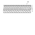
- FIG. 1 is a cross-sectional view schematically showing a laminate according to a first embodiment of the invention.
- FIG. 2 is a cross-sectional view schematically showing a laminate according to a second embodiment of the invention.
- FIG. 3 is a cross-sectional view schematically showing a laminate according to a third embodiment of the invention.
- FIG. 4 is a cross-sectional view schematically showing a laminate according to a fourth embodiment of the invention.
- FIG. 5 is a cross-sectional view schematically showing a laminate according to a fifth embodiment of the invention.
- FIG. 6 is a cross-sectional view schematically showing a laminate according to a sixth embodiment of the invention.
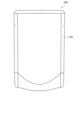
- FIG. 7 is a diagram schematically showing a packaged article according to a seventh embodiment of the invention.
- FIG. 8 is a diagram schematically showing a packaged article according to an eighth embodiment of the invention.
- FIG. 9 is a diagram schematically showing a packaged article according to a ninth embodiment of the invention.
- AA on BB is used regardless of the direction of gravity.
- the condition identified by the statement “AA on BB” encompasses the condition where AA is in contact with BB.
- Reference to “AA over BB” does not exclude the interposition of one or more other components between AA and BB.
- Laminate Fig. 1 is a sectional view schematically showing a laminate according to a first embodiment of the present invention.
- a laminate 10A shown in FIG. 1 includes a substrate layer 2, a gas barrier layer 3, a printing layer 4, an adhesive layer 5, and a sealant layer 6 in this order.
- the ratio of polyethylene in the laminate 10A is 90% by mass or more.
- the ratio of polyethylene in the laminate 10A means the ratio of the total amount of polyethylene to the total amount of the resin material in each layer constituting the laminate 10A. High recyclability can be achieved by setting the proportion of polyethylene to 90% by mass or more.
- the base material layer 2 contains polyethylene.
- Polyethylene may be a homopolymer of ethylene or a copolymer of ethylene and other monomers. When polyethylene is a copolymer of ethylene and other monomers, the proportion of ethylene in the copolymer is, for example, 80 mol % or more.
- ⁇ -olefins include ⁇ -olefins.
- the ⁇ -olefins range from 3 to 20 carbon atoms.
- Such ⁇ -olefins are, for example, propylene, 1-butene, 1-pentene, 1-hexene, 1-octene, 1-decene, 1-dodecene, 1-tetradecene, 1-hexadecene, 1-octadecene, 1- eicosene, 3-methyl-1-butene, 4-methyl-1-pentene, or 6-methyl-1-heptene.
- the polyethylene may be a copolymer of ethylene and one of vinyl acetate and acrylic acid ester.
- the base material layer 2 is, for example, high density polyethylene (HDPE), medium density polyethylene (MDPE), low density polyethylene (LDPE), linear low density polyethylene (LLDPE), or very low density polyethylene (VLDPE).
- high-density polyethylene and medium-density polyethylene are preferable from the viewpoint of the printability, strength and heat resistance of the laminate 10A and the film stretchability, and medium-density polyethylene is more preferable from the viewpoint of stretchability.
- high-density polyethylene has a density of 0.942 g/cm 3 or more
- medium-density polyethylene has a density of 0.930 g/cm 3 or more and less than 0.942 g/cm 3
- low-density polyethylene has a density of is 0.910 g/cm 3 or more and less than 0.930 g/cm 3
- the linear low density polyethylene has a density of 0.910 g/cm 3 or more and less than 0.930 g/cm 3
- the ultra-low density polyethylene has a density of is less than 0.910 g/cm 3
- the density is a value obtained by a method conforming to JIS K7112:1999.
- the polyethylene contained in the base material layer 2 may be biomass-derived polyethylene.
- biomass-derived polyethylene for example, green polyethylene (manufactured by Braskem) can be used.
- the polyethylene contained in the base material layer 2 may be polyethylene recycled by mechanical recycling.
- mechanical recycling means pulverizing the recovered polyethylene film or the like, then cleaning the pulverized film with alkali to remove dirt and foreign matter on the film surface, and then drying it at high temperature and under reduced pressure. It is to decontaminate the polyethylene film by dispersing the retained contaminants.
- the polyethylene contained in the base material layer 2 may be polyethylene recycled by chemical recycling.
- the base material layer 2 has an absolute value of 1.07 or more for the degree of molecular orientation measured by the microwave method (that is, Microwave Orientation Ratio; MOR).
- the absolute value of the degree of molecular orientation measured by the microwave method is also simply referred to as the "degree of molecular orientation" in this specification.
- the degree of molecular orientation is an index representing the extent to which the directions of molecular chains are aligned. That is, a high degree of molecular orientation means that the directions of the molecular chains are aligned.
- a layer with a degree of molecular orientation of 1.07 or more is excellent in heat resistance, and a film with a high degree of molecular orientation has a small spherulite size, so that it is excellent in transparency and can sufficiently ensure visibility.
- by increasing the degree of molecular orientation it is possible to impart toughness to the film, thereby improving impact resistance and puncture resistance.
- the degree of molecular orientation of the substrate layer 2 is preferably 1.10 or more, more preferably 1.15 or more, still more preferably 1.20 or more, still more preferably 1.25 or more, and still more preferably 1.30 or more. . By increasing the degree of molecular orientation of the substrate layer 2, the above effect can be further improved.
- the upper limit of the degree of molecular orientation of the substrate layer 2 is not particularly limited, but is, for example, 2.0 or less, 1.8 or less, or 1.5 or less.
- the degree of molecular orientation of the base material layer 2 is determined by the density of the resin (especially polyethylene) used for the base material layer 2, in addition to the drawing conditions such as the draw ratio in each of the MD direction (machine direction) and the TD direction (transverse direction). , type of comonomer, molecular weight, molecular weight distribution, manufacturing method, and other factors.
- the rheological properties of the molten resin when the resin film is stretched are also factors that affect the degree of molecular orientation. Even when stretching is performed at the same draw ratio, the degree of molecular orientation can be adjusted by changing the various factors described above. Further, the degree of molecular orientation can also be adjusted when a shear stress is applied to the molten resin in the film forming stage.
- the degree of molecular orientation is measured by the microwave method as described above. That is, the degree of molecular orientation is measured by a perturbation method using a microwave cavity. Specifically, the degree of molecular orientation can be measured using a microwave type molecular orientation meter such as a molecular orientation meter MOA-5012A (manufactured by Oji Scientific Instruments Co., Ltd.).
- a microwave-type molecular orientation meter rotates a sheet-shaped sample in a microwave polarized electric field, and measures the orientation of the molecular chains in the sheet from the interaction between the microwave electric field and the dipoles that make up the polymer material. It is.
- a sample having a square shape with a side length of 35 mm and a thickness of 2 mm or less is used, and the measurement frequency is 12.0 GHz to 13.0 GHz. .0 GHz range.
- the degree of molecular orientation is measured for each of a plurality of locations on the substrate layer 2 , and the average value of the obtained degrees of molecular orientation is obtained as the degree of molecular orientation of the substrate layer 2 .
- the plurality of locations of the base material layer 2 are, for example, the central portion and end portions of the base material layer 2 .
- the base material layer 2 is preferably a stretched film.
- the substrate layer 2 may be a uniaxially stretched film or a biaxially stretched film.
- film does not include the concept of thickness.
- Using a uniaxially stretched film as the base material layer 2 improves the heat resistance during bag making.
- a biaxially stretched film is used as the base material layer 2
- the drop strength of the packaged article using the laminate 10A as the packaging material is improved.
- Whether the stretched film is a uniaxially stretched film or a biaxially stretched film can be determined by performing in-plane measurement using a wide-angle X-ray diffraction method, as described below.
- the X-ray diffraction pattern obtained by this measurement contains information on the degree of orientation of molecular chains present on the film surface. An example of the measurement method is shown.
- out-of-plane measurement is performed by the parallel beam method.
- An X-ray diffraction pattern of the film to be measured is obtained by 2 ⁇ / ⁇ scanning over a range of diffraction angles of 10° to 30°.
- CuK ⁇ rays are used as the X-rays, and the X-rays are collimated by a multilayer film mirror and made incident on the base material layer 1 .
- a scintillation detector with a flat plate collimator is used as the light receiving unit.
- the peak area of the crystalline component and the halo pattern area of the amorphous component are obtained, and the ratio of the peak area of the crystalline component to the total area is calculated as the degree of crystallinity.
- the crystallinity of one of the outermost surfaces of the film is measured.
- the film to be measured is a polyethylene film
- scanning at a diffraction angle of 10° to 30° reveals two sharp crystal component peaks corresponding to the (110) plane and the (200) plane, A broad halo pattern of the amorphous component is observed.
- the film to be measured is a uniaxially stretched film or a biaxially stretched film
- in-plane measurement by the X-ray diffraction method, as described above.
- the X-ray incident angle ⁇ and the angle 2 ⁇ at which the diffracted X-rays are detected by the detector correspond to the specific crystal planes in the above out-of-plane measurement.
- Diffraction peaks for example, the angle ⁇ and angle 2 ⁇ when the diffraction peak corresponding to the (110) plane of a polyethylene film is detected are fixed, and in this state, the film to be measured is scanned in the in-plane direction. to obtain a diffraction pattern.
- in-plane measurement is performed on a uniaxially stretched film uniaxially stretched in the machine direction (MD)
- MD direction is defined as 0 °
- a sharp diffraction peak corresponding to the (110) plane is formed at an angle 2 ⁇ of about
- a diffraction pattern with positions of ⁇ 90° can be obtained.
- biaxially stretched film the higher-order structure obtained by the uniaxial stretching is disturbed by the second stretching, and the anisotropy is reduced.
- a diffraction pattern having a uniform diffraction peak cannot be obtained. Therefore, in-plane measurements can be cited as one method of distinguishing monoaxially and biaxially stretched films from each other.
- a higher-order structure When a polymer film is uniaxially stretched, a higher-order structure called a shish kebab structure appears.
- the shish kebab structure consists of a shish structure, which is an extended chain crystal, and a kebab structure, which is a lamellar crystal.
- this higher-order structure In a uniaxially stretched film, this higher-order structure is arranged with a high degree of order, so the X-ray diffraction pattern obtained by the above measurement for the uniaxially stretched film will contain sharp diffraction peaks. That is, when the above measurement is performed on the uniaxially stretched film, a clear diffraction peak appears.
- a "clear diffraction peak” means a diffraction peak with a half width of less than 10°.
- the uniaxially stretched film and the biaxially stretched film have different X-ray diffraction patterns obtained by the above measurement. Therefore, based on this, it is possible to determine whether the stretched film is a monoaxially stretched film or a biaxially stretched film.
- the stretching ratios of the stretched film in the machine direction (MD) and the transverse direction (TD) are preferably 2 to 10 times, more preferably 3 to 7 times.
- the strength and heat resistance of the laminate 10A can be improved, and the printability of the base material layer 2 can be improved.
- the transparency of the substrate layer 2 can be improved by setting the stretching ratio in the MD direction or the TD direction to 2 times or more, the visibility of the contents and the printed layer can be improved.
- the upper limit of the stretching ratio in the MD direction and the TD direction of the stretched film is not particularly limited, but from the viewpoint of the breaking limit of the stretched film, it is preferably 10 times or less.
- the film can be produced by a known production method such as a casting method or an inflation method. It is also possible to use, as the substrate layer 2, a multi-layered polyethylene film obtained by co-extrusion of polyethylenes having different densities.
- a multi-layered structure comprising a layer made of high density polyethylene (high density polyethylene layer) and a layer made of medium density polyethylene (medium density polyethylene layer) may be used.
- high density polyethylene layer high density polyethylene layer
- medium density polyethylene layer medium density polyethylene layer
- the haze of the base material layer 2 is preferably 20% or less, more preferably 10% or less. Such a base material layer 2 can improve the visibility of the contents and the printed layer.
- the haze is a value obtained by a method conforming to JIS K7136:2000.
- the thickness of the base material layer 2 is preferably in the range of 10 ⁇ m to 200 ⁇ m, more preferably in the range of 15 ⁇ m to 50 ⁇ m. If the base material layer 2 is too thin, the strength of the laminate 10A tends to decrease. Moreover, if the base material layer 2 is too thick, the processability of 10 A of laminated bodies will fall easily.
- the base material layer 2 is preferably surface-treated. According to this treatment, the adhesion between the substrate layer 2 and the layer adjacent to the substrate layer 2 can be improved.
- the surface treatment method is not particularly limited.
- Surface treatments include, for example, corona discharge treatment, ozone treatment, low-temperature plasma treatment using oxygen gas and/or nitrogen gas, physical treatment such as glow discharge treatment, and chemical treatment such as oxidation treatment using chemicals. processing.
- the base material layer 2 may further contain additives.
- additives include cross-linking agents, antioxidants, anti-blocking agents, slip agents, UV absorbers, light stabilizers, fillers, reinforcing agents, antistatic agents, pigments, and modifying resins. is mentioned.
- the proportion of polyethylene in the base material layer 2 is preferably 50% by mass or more, more preferably 80% by mass or more.
- the substrate layer 2 consists of polyethylene.
- the base layer 2 consists of polyethylene and additives.
- the gas barrier layer 3 improves, for example, the oxygen barrier property and the water vapor barrier property of the laminate 10A.
- the gas barrier layer 3 consists of an inorganic compound layer, or consists of an inorganic compound layer and a coating layer.
- the gas barrier layer 3 is composed of an inorganic compound layer and a coating layer, it is preferable to laminate the inorganic compound layer and the coating layer in this order from the substrate layer 2 side.
- the gas barrier layer 3 may be formed by coating, or may be formed by depositing an inorganic compound.
- Examples of inorganic compounds contained in the inorganic compound layer include metal oxides such as aluminum oxide, silicon oxide, magnesium oxide, and tin oxide.
- the inorganic compound layer is preferably a deposited film made of, for example, a metal oxide.
- the metal oxide may be selected from the group consisting of aluminum oxide, silicon oxide and magnesium oxide.
- the metal oxide is selected from aluminum oxide and silicon oxide.
- the film thickness of the deposited film made of aluminum oxide is preferably 5 nm or more and 30 nm or less. Sufficient gas-barrier property can be obtained as a film thickness is 5 nm or more. Further, when the film thickness is 30 nm or less, it is possible to suppress the occurrence of cracks due to deformation due to internal stress of the thin film, and to suppress deterioration of gas barrier properties. If the film thickness exceeds 30 nm, the cost tends to increase due to an increase in the amount of material used and an increase in film formation time, which is not preferable from an economic point of view. From the same point of view as above, the film thickness of the deposited film made of aluminum oxide is more preferably 7 nm or more and 15 nm or less.
- the film thickness of the deposited film made of silicon oxide is preferably 10 nm or more and 50 nm or less. Sufficient gas-barrier property can be obtained as a film thickness is 10 nm or more. Further, when the film thickness is 50 nm or less, it is possible to suppress the generation of cracks due to deformation due to internal stress of the thin film, and to suppress deterioration of gas barrier properties. If the film thickness exceeds 50 nm, it is not preferable from an economical point of view because the cost tends to increase due to an increase in the amount of material used and an increase in film formation time. From the same viewpoint as above, the film thickness of the deposited film made of silicon oxide is more preferably 20 nm or more and 40 nm or less.
- the inorganic compound layer can be formed, for example, by vacuum deposition.
- a physical vapor deposition method or a chemical vapor deposition method can be used.
- the physical vapor deposition method include a vacuum deposition method, a sputtering method, an ion plating method, and the like, but are not limited to these.
- the chemical vapor deposition method include a thermal CVD (Chemical Vapor Deposition) method, a plasma CVD method, an optical CVD method, and the like, but are not limited to these.
- the resistance heating vacuum deposition method In the vacuum film formation, the resistance heating vacuum deposition method, the EB (Electron Beam) heating vacuum deposition method, the induction heating vacuum deposition method, the sputtering method, the reactive sputtering method, the dual magnetron sputtering method, and the plasma chemical vapor deposition method. (PECVD method) and the like are particularly preferably used. However, in terms of productivity, the vacuum deposition method is currently the best.
- a heating means for the vacuum vapor deposition method it is preferable to use any one of an electron beam heating method, a resistance heating method, and an induction heating method.
- a known anchor coating agent may be used to form an anchor coating layer on the surface of the substrate layer 2 on which the inorganic compound layer is formed. Thereby, the adhesion of the inorganic compound layer made of metal oxide can be improved.
- anchor coating agents include polyester-based polyurethane resins and polyether-based polyurethane resins. From the viewpoint of heat resistance and interlayer adhesive strength, the anchor coating agent is preferably a polyester-based polyurethane resin.
- the coating layer can be formed, for example, by coating.
- a coating liquid containing resin such as polyvinyl alcohol (PVA), ethylene-vinyl alcohol copolymer, ethylene-vinyl acetate copolymer, polyvinylidene chloride, polyacrylonitrile, and epoxy resin can be used.
- Additives such as organic or inorganic particles, layered compounds, and curing agents may be added to the coating liquid.
- the coating layer is, for example, an organic-inorganic composite layer containing at least one of a metal alkoxide, a hydrolyzate of a metal alkoxide, and a reaction product of a metal alkoxide or a hydrolyzate of a metal alkoxide, and a water-soluble polymer. good.
- the organic-inorganic composite layer further contains at least one of a silane coupling agent, a hydrolyzate of the silane coupling agent, and a reaction product of the silane coupling agent or the hydrolyzate of the silane coupling agent. good.
- Metal alkoxides and hydrolysates thereof contained in the organic-inorganic composite layer include, for example, tetraethoxysilane [Si(OC 2 H 5 ) 4 ] and triisopropoxyaluminum [Al(OC 3 H 7 ) 3 ]. Included are those represented by the formula M(OR) n , as well as hydrolysates thereof. In the general formula above, M represents a metal and R represents an alkyl group. One of these may be contained alone or in combination of two or more.
- the total content of the metal alkoxide, its hydrolyzate, or their reaction product in the coating liquid used to form the organic-inorganic composite layer may be, for example, 40% by mass or more from the viewpoint of oxygen barrier properties. It may be at least 65% by mass. Moreover, the total content of the metal alkoxide, its hydrolyzate, or reaction product thereof in the coating liquid may be, for example, 70% by mass or less.
- the water-soluble polymer contained in the organic-inorganic composite layer is not particularly limited, and examples thereof include polyvinyl alcohol, polysaccharides such as starch, methylcellulose, carboxymethylcellulose, and hydroxyl group-containing polymers such as acrylic polyol. From the viewpoint of further improving the oxygen gas barrier property, the water-soluble polymer preferably contains a polyvinyl alcohol-based water-soluble polymer.
- the water-soluble polymer has a number average molecular weight of, for example, 40,000 to 180,000.
- the polyvinyl alcohol-based water-soluble polymer contained in the organic-inorganic composite layer can be obtained, for example, by saponifying polyvinyl acetate (including partial saponification).
- This water-soluble polymer may have several tens of percent of acetic acid groups remaining, or may have only several percent of acetic acid groups remaining.
- the content of the water-soluble polymer in the coating liquid used for forming the organic-inorganic composite layer may be, for example, 15% by mass or more, or 20% by mass or more from the viewpoint of oxygen barrier properties. Moreover, the content of the water-soluble polymer in the coating liquid may be, for example, 50% by mass or less, or 45% by mass or less from the viewpoint of oxygen barrier properties.
- Silane coupling agents used in the organic-inorganic composite layer include silane coupling agents having organic functional groups.
- silane coupling agents include ethyltrimethoxysilane, vinyltrimethoxysilane, ⁇ -chloropropylmethyldimethoxysilane, ⁇ -chloropropyltrimethoxysilane, glycidoxypropyltrimethoxysilane, ⁇ -methacryloxypropyltrimethoxysilane. methoxysilane, ⁇ -methacryloxypropylmethyldimethoxysilane, and the like.
- a silane coupling agent selected from these, a hydrolyzate thereof and a reaction product thereof can be used singly or in combination of two or more thereof.
- silane coupling agent it is preferable to use one having an epoxy group as an organic functional group.
- Silane coupling agents having an epoxy group include, for example, ⁇ -glycidoxypropyltrimethoxysilane and ⁇ -(3,4-epoxycyclohexyl)ethyltrimethoxysilane.
- a silane coupling agent having an epoxy group may have an organic functional group different from the epoxy group, such as a vinyl group, an amino group, a methacryl group or a ureyl group.
- a silane coupling agent selected from these, a hydrolyzate thereof and a reaction product thereof can be used singly or in combination of two or more thereof.
- a silane coupling agent having an organic functional group, a hydrolyzate thereof, or a reaction product thereof enhances the oxygen barrier property of the organic-inorganic composite layer and the adjacent It is possible to further improve the adhesion with the layer to be coated.
- the silane coupling agent, its hydrolyzate, or reaction product thereof has an epoxy group
- the water-soluble polymer is polyvinyl alcohol (PVA)
- PVA polyvinyl alcohol
- the total content of the silane coupling agent, its hydrolyzate and their reaction products in the coating liquid used to form the organic-inorganic composite layer may be, for example, 1% by mass or more from the viewpoint of oxygen barrier properties. , 2% by mass or more. Further, the total content of the silane coupling agent, its hydrolyzate, and their reaction products in the coating liquid may be, for example, 15% by mass or less, or 12% by mass or less, from the viewpoint of oxygen barrier properties. you can
- the thickness of the coating layer is preferably 50 nm or more and 1000 nm or less, more preferably 100 nm or more and 500 nm or less.
- the thickness of the gas barrier coating layer is 50 nm or more, it tends to be possible to obtain more sufficient gas barrier properties, and when it is 1000 nm or less, it tends to be able to maintain sufficient flexibility.
- the gas barrier layer 3 is preferably subjected to the surface treatment described above. Thereby, the adhesion between the gas barrier layer 3 and the adjacent layer can be improved.
- a nanocomposite may be used as the material for the gas barrier layer 3 .
- the printed layer 4 is a layer made of ink and displays patterns such as characters and pictures.
- the inks are, for example, conventionally used ink binder resins such as urethane, acrylic, nitrocellulose, rubber, and vinyl chloride, various pigments, extenders, plasticizers, desiccants, stabilizers, etc. of additives are added.
- As the ink it is preferable to use biomass-derived ink.
- a light-shielding ink can also be preferably used. Examples of light-shielding ink include white ink, black ink, silver ink, and sepia ink.
- Examples of methods for forming the printed layer 4 include known printing methods such as offset printing, gravure printing, flexographic printing and silk screen printing, and known coating methods such as roll coating, knife edge coating, and gravure coating. method can be used.
- water-based flexographic printing is preferable from the viewpoint of environmental problems, as it has a small printing load on the substrate layer.
- the adhesive layer 5 contains at least one type of adhesive.
- the adhesive may be a one-component curable adhesive, a two-component curable adhesive, or a non-curable adhesive. Further, the adhesive may be a non-solvent adhesive or a solvent adhesive.
- adhesives examples include polyether adhesives, polyester adhesives, silicone adhesives, epoxy adhesives such as polyamine adhesives, urethane adhesives, rubber adhesives, vinyl adhesives, and silicone adhesives. adhesives, epoxy adhesives, phenol adhesives and olefin adhesives. Adhesives containing biomass components can also be preferably used.
- an epoxy-based adhesive such as a polyamine-based adhesive having gas barrier properties, or a urethane-based adhesive such as a polyester/polyurethane-based adhesive is preferably used.
- gas barrier adhesives include "Maxieve” manufactured by Mitsubishi Gas Chemical Company and "Paslim” manufactured by DIC.
- the adhesive layer 5 may be a cured product of a resin composition containing a polyester polyol, an isocyanate compound and a phosphoric acid-modified compound. Such an adhesive layer 5 can further improve the oxygen barrier properties and water vapor barrier properties of the laminate 10A.
- the thickness of the adhesive layer 5 is preferably in the range of 0.1 ⁇ m to 20 ⁇ m, more preferably in the range of 0.5 ⁇ m to 10 ⁇ m, even more preferably in the range of 1 to 5 ⁇ m. .
- the adhesive layer 5 is applied onto the sealant layer 6 by a conventionally known method such as a direct gravure roll coating method, a gravure roll coating method, a kiss coating method, a reverse roll coating method, a fonten method and a transfer roll coating method, and then dried. It can be formed by
- the sealant layer 6 contains polyethylene.
- the polyethylene for example, the polyethylene contained in the base material layer 2 can be used.
- the sealant layer 6 is preferably low density polyethylene (LDPE), linear low density polyethylene (LLDPE) or very low density polyethylene (VLDPE), more preferably linear low density polyethylene.
- polyethylene is preferably biomass-derived polyethylene or recycled polyethylene.
- the sealant layer 6 may be transparent or opaque. In the latter case, the sealant layer 6 may be colored, preferably white.
- the laminate 10A having a transparent sealant layer 6 makes it easy to visually recognize the contents when used as a package. When the laminated body 10A with the opaque sealant layer 6 is used as a package, the content does not hinder the visibility of the image displayed by the printed layer 4. - ⁇ In particular, the white sealant layer 6 improves the visibility of the image displayed by the printed layer 4 .
- the sealant layer 6 may further contain the additives described above in the section " ⁇ 1.2> Base material layer".
- the proportion of polyethylene in the sealant layer 6 is preferably 50% by mass or more, more preferably 80% by mass or more.
- the sealant layer 6 consists of polyethylene.
- the sealant layer 6 consists of polyethylene and additives.
- the thickness of the sealant layer 6 can be appropriately set in consideration of the shape of the packaging bag to be manufactured, the mass of the contents to be contained, and the like, and can be, for example, in the range of 30 to 150 ⁇ m.
- the sealant layer 6 is, for example, an unstretched polyethylene resin film or a layer formed by melt extrusion of polyethylene.
- the sealant layers of the laminate are brought into contact with each other, and the contact portions are sandwiched between jigs to apply pressure and heat, thereby heat-sealing the contact portions.
- the jig of the heat-sealing machine is at a high temperature, and the surface of the base material layer in direct contact with the jig is exposed to high temperature.
- polyethylene which is inferior in heat resistance
- the surface of the substrate layer may be affected by heat, causing problems such as adhesion to jigs. Therefore, conventional laminates using polyethylene as a base layer have a problem of poor productivity due to narrow appropriate bag-making temperature conditions.
- the present inventors have found that when the degree of molecular orientation of the substrate layer 2 is 1.07 or more, the substrate layer 2 exhibits excellent heat resistance, and therefore the laminate 10A also exhibits excellent heat resistance. It has been found that particularly good heat-sealability is achieved.
- polyethylene which is generally said to have poor heat resistance
- the degree of molecular orientation of the base material layer 2 is 1.07 or more, the temperature range of heat sealing performed for bag making is widened, and productivity is not lowered.
- the laminate 10A has a polyethylene content of 90% by mass or more. Therefore, the laminate 10A is also excellent in recyclability.
- the laminate 10A includes the printed layer 4 between the gas barrier layer 3 and the adhesive layer 5. It may be provided at any position in between.
- the printed layer 4 may be provided on the surface of the base material layer 2 facing the sealant layer 6 (that is, the back surface of the base material layer 2).
- the printed layer 4 may be provided on the surface of the base material layer 2 .
- a plurality of printed layers 4 may be provided. Since the substrate layer 2 has excellent transparency, even when the printed layer 4 is included between the substrate layer 2 and the sealant layer 6, when the laminate 10A is observed from the substrate layer 2 side, the printed layer The pattern displayed by 4 can be clearly seen. Alternatively, the printing layer 4 may be omitted.
- an anchor coat layer may be formed on the main surface of the base material layer 2 that faces the gas barrier layer 3 .
- the gas barrier layer 3 may be omitted.
- a metal deposition layer may be provided on the base material layer 2 or the sealant layer 6 in order to impart light shielding properties to the laminate 10A.
- a metal deposition layer may be provided on the intermediate layer.
- An aluminum vapor deposition layer can be mentioned as a metal vapor deposition layer.
- the sealant layer 6 may be opaque
- the base material layer 2 may also be opaque.
- the substrate layer 2 may be colored, for example white.
- the intermediate layer may be opaque.
- the intermediate layer may be colored, for example white.
- FIG. 2 is a cross-sectional view schematically showing a laminate according to a second embodiment of the present invention.
- a layered body 10B shown in FIG. 2 is the same as the layered body 10A except that it further includes a protective layer 1 provided on the surface of the substrate layer 2 .
- the protective layer 1 is the outermost layer facing the sealant layer 6 with the base material layer 2 interposed therebetween. Here, the protective layer 1 covers the surface of the base material layer 2 .
- the protective layer 1 is made of a thermosetting resin. That is, the protective layer 1 is a thermosetting resin layer.
- the cured product of the thermosetting resin is not particularly limited as long as it has heat resistance.
- Thermosetting resins include, for example, polyurethane resins, polyester resins, polyamide resins, polyamideimide resins, acrylic resins, and epoxy resins.
- the protective layer 1 may contain one type of the above thermosetting resin, or may contain two or more types.
- the protective layer 1 preferably contains a water-soluble polymer, and is preferably an organic-inorganic composite layer containing an organometallic compound.
- water-soluble polymers examples include polyvinyl alcohol, polysaccharides such as starch, methylcellulose, carboxymethylcellulose, and hydroxyl group-containing polymers such as acrylic polyol.
- the protective layer 1 preferably contains a polyvinyl alcohol-based hydroxyl group-containing polymer that can be contained in a coating layer as the gas barrier layer 3 described later.
- the protective layer 1 preferably contains at least one of a metal alkoxide, a hydrolyzate of a metal alkoxide, and a reaction product of a metal alkoxide or a hydrolyzate thereof as an organometallic compound.
- metal alkoxides include those represented by the general formula M(OR) n such as tetraethoxysilane [Si( OC2H5 ) 4 ] and triisopropoxyaluminum [Al( OC3H7 ) 3 ]. mentioned.
- the protective layer 1 further includes at least one of a silane coupling agent, a hydrolyzate of the silane coupling agent, and a reaction product of the silane coupling agent or a hydrolyzate of the silane coupling agent as the organometallic compound. It is preferred to include
- the protective layer 1 can be formed using a coating liquid for forming a coating layer as the gas barrier layer 3, which will be described later. Further, when the laminate 10B includes an inorganic compound layer and a coating layer as the gas barrier layer 3, the protective layer 1 is a layer formed using the same coating liquid as the coating liquid used to form the coating layer. you can
- the thickness of protective layer 1 is preferably 0.3 ⁇ m or more. Moreover, when the thickness of the protective layer 1 increases, it tends to become difficult to sufficiently dry the resin coating film in the manufacturing process of the laminate 10B. From the viewpoint of productivity, the thickness of protective layer 1 is preferably 3 ⁇ m or less.
- the laminate 10B includes the protective layer 1 .
- the protective layer 1 reduces thermal damage during heat sealing on the surface of the laminate 10B. Therefore, the laminate 10B can achieve even better heat resistance, particularly better heat-sealability. Therefore, when the laminate 10B has the configuration described above, the temperature range for heat sealing for bag making is widened, and the decrease in productivity is less likely to occur.
- the protective layer 1 is substantially transparent, even if the laminate 10B further includes the protective layer 1, the image displayed by the printed layer 4 can be visually recognized from the surface side. That is, the laminate 10B has excellent transparency and further excellent heat resistance. Moreover, since the laminate 10B has a ratio of polyethylene of 90% by mass or more, it is also excellent in recyclability.
- the laminate 10B includes the printed layer 4 between the gas barrier layer 3 and the adhesive layer 5. may be provided at any position. Since the substrate layer 2 has excellent transparency, even when the printed layer 4 is included between the protective layer 1 and the sealant layer 6, when the laminate 10B is observed from the protective layer 1 side, the printed layer 4 is The displayed pattern can be clearly seen. Alternatively, the printing layer 4 may be omitted.
- an anchor coat layer may be formed on the main surface of the base material layer 2 that faces the gas barrier layer 3 .
- the gas barrier layer 3 may be omitted.
- Laminate Fig. 3 is a sectional view schematically showing a laminate according to a third embodiment of the present invention.
- a laminate 10C shown in FIG. 3 is the same as the laminate 10A except for the following items. That is, the laminate 10C further includes an intermediate layer 7. As shown in FIG. Moreover, the laminate 10C includes a first adhesive layer 5A and a second adhesive layer 5B instead of the adhesive layer 5. As shown in FIG. That is, the laminate 10C includes the substrate layer 2, the printed layer 4, the first adhesive layer 5A, the intermediate layer 7, the gas barrier layer 3, the second adhesive layer 5B, and the sealant layer 6. Including in order.
- the intermediate layer 7 is interposed between the base material layer 2 and the sealant layer 6 .
- the intermediate layer 7 contains polyethylene.
- the intermediate layer 7 has an absolute value of the degree of molecular orientation measured by a microwave method of 1.07 or more, preferably 1.10 or more, more preferably 1.15 or more. It is preferably 1.20 or more, more preferably 1.25 or more, and still more preferably 1.30 or more.
- the upper limit of the degree of molecular orientation of the intermediate layer 7 is not particularly limited, but is, for example, 2.0 or less, 1.8 or less, or 1.5 or less.
- Such an intermediate layer 7 is excellent in transparency and can contribute to improving the strength of the laminate 10C, particularly the puncture strength.
- the "puncture strength" of the laminate is a value obtained when the laminate 10C is pierced from the base layer 2 side in the method specified in JIS Z1707:2019 "General Rules for Plastic Films for Food Packaging". Specifically, a needle with a diameter of 1 mm and a semicircular tip is pierced into the laminated body 10C from the base layer 2 side at a speed of 50 mm/min, and the maximum force until the needle penetrates is measured. do. This measurement is performed multiple times and the arithmetic mean of the maximum force is obtained as the puncture strength.
- the intermediate layer 7 is, for example, high density polyethylene (HDPE), medium density polyethylene (MDPE), low density polyethylene (LDPE), linear low density polyethylene (LLDPE) or very low density polyethylene (VLDPE).
- high-density polyethylene and medium-density polyethylene are preferable from the viewpoint of printability, strength and heat resistance of the laminate 10C, and film stretchability, and medium-density polyethylene is more preferable from the viewpoint of stretchability.
- the polyethylene contained in the intermediate layer 7 may be the same as or different from the polyethylene contained in the base material layer 2.
- the intermediate layer 7 may further contain the additives described above.
- the intermediate layer 7 is preferably a stretched film.
- the intermediate layer 7 may be a uniaxially stretched film or a biaxially stretched film.
- the stretched film forming the intermediate layer 7 may be the same as or different from the stretched film forming the base layer 2 .
- Using a uniaxially stretched film as the intermediate layer 7 improves the heat resistance during bag making.
- a biaxially oriented film is used as the intermediate layer 7, the drop strength of the packaged article using the laminate 10C as the packaging material is improved.
- the stretched film is a uniaxially stretched film or a biaxially stretched film can be determined by performing in-plane measurement using the X-ray diffraction method, as described in the section of the first embodiment.
- the average of the degree of molecular orientation measured at the central portion and the end portions of the intermediate layer 7 is preferably 1.07 or more. It is more preferably 1.07 or more.
- the degree of molecular orientation of the intermediate layer 7 can also be adjusted by selecting the material, as described for the degree of molecular orientation of the base layer 2 in the section " ⁇ 1.2> Base layer" in the first embodiment. .
- the stretched film forming the intermediate layer 7 may be the same as or different from the stretched film forming the base layer 2 .
- an intermediate layer having an absolute value of the degree of molecular orientation measured by a microwave method of less than 1.07 may be used.
- an intermediate layer whose absolute value of the degree of molecular orientation measured by a microwave method is less than 1.07 the strength of the laminate 10C, particularly drop strength, can be improved.
- An unstretched film is preferable as the intermediate layer having an absolute value of the degree of molecular orientation of less than 1.07 as measured by a microwave method.
- the proportion of polyethylene in the intermediate layer 7 is preferably 50% by mass or more, more preferably 80% by mass or more.
- the intermediate layer 7 consists of polyethylene.
- the intermediate layer 7 consists of polyethylene and additives.
- the thickness of the intermediate layer 7 is preferably in the range of 10 ⁇ m to 200 ⁇ m, more preferably in the range of 15 ⁇ m to 50 ⁇ m.
- the intermediate layer 7 can be produced by a known method such as the above-described casting method or inflation method, and a multi-layered polyethylene film obtained by extruding polyethylene having different densities by a co-extrusion method is used as the intermediate layer 7. is also possible.
- the intermediate layer 7 is preferably surface-treated like the base material layer 2 . According to this treatment, the adhesion between the intermediate layer 7 and the adjacent layer can be improved.
- the surface treatment method is not particularly limited. Surface treatments include, for example, corona discharge treatment, ozone treatment, low-temperature plasma treatment using oxygen gas and/or nitrogen gas, physical treatment such as glow discharge treatment, and chemical treatment such as oxidation treatment using chemicals. processing.
- Adhesive Layer The first adhesive layer 5A is interposed between the printed layer 4 and the intermediate layer 7 to bond them together.
- the second adhesive layer 5B is interposed between the gas barrier layer 3 and the sealant layer 6 to bond them together.
- the adhesive for forming the first adhesive layer 5A and the second adhesive layer 5B As the adhesive for forming the first adhesive layer 5A and the second adhesive layer 5B, the adhesive described in the section " ⁇ 1.5> Adhesive layer" in the first embodiment can be used. can.
- the material of the second adhesive layer 5B may be the same as or different from the material of the first adhesive layer 5A.
- the thickness of the first adhesive layer 5A and the second adhesive layer 5B is preferably in the range of 0.1 ⁇ m to 20 ⁇ m, more preferably in the range of 0.5 ⁇ m to 10 ⁇ m, and 1 to 5 ⁇ m. is more preferably within the range of
- the first adhesive layer 5A and the second adhesive layer 5B are formed, for example, by a conventionally known method such as a direct gravure roll coating method, a gravure roll coating method, a kiss coating method, a reverse roll coating method, a fonten method and a transfer roll coating method. It can be formed by coating and drying on the base material layer 2 or the sealant layer 6 .
- the laminate 10C is excellent in heat resistance and transparency, like the laminate 10A.
- the laminate 10C includes an intermediate layer 7 having a degree of molecular orientation of 1.07 or more.
- This intermediate layer 7 enhances the strength of the laminate 10C, especially the puncture strength. Therefore, the laminate 10C is excellent in strength, especially puncture strength.
- the laminate 10C has a polyethylene ratio of 90% by mass or more, it is also excellent in recyclability.
- laminates with a high proportion of polyethylene are weaker in stiffness than other laminates, and are therefore more likely to be bent when used as packaging materials. As the chances of bending increase, the possibility of pinhole formation increases.
- the laminated body 10C which has excellent piercing strength, is less prone to pinhole formation.
- the laminate 10C includes the printed layer 4 between the base material layer 2 and the first adhesive layer 5A. 6 may be provided. Since the substrate layer 2 and the intermediate layer 7 are excellent in transparency, even when the print layer 4 is included between the substrate layer 2 and the sealant layer 6, when the laminate 10C is observed from the substrate layer 2 side 2, the pattern displayed by the printed layer 4 can be clearly seen. Alternatively, the printing layer 4 may be omitted.
- an anchor coat layer may be formed on the main surface of the base material layer 2 that faces the printed layer 4 .
- the gas barrier layer 3 may be omitted.
- Laminate Fig. 4 is a sectional view schematically showing a laminate according to a fourth embodiment of the present invention.
- a layered body 10D shown in FIG. 4 is the same as the layered body 10C except that the protective layer 1 provided on the surface of the base material layer 2 is further included.
- the protective layer 1 the one described in the second embodiment can be used.
- the degree of molecular orientation of the substrate layer 2 is 1.07 or more.
- the laminated body 10 ⁇ /b>D includes a protective layer 1 . Therefore, the laminate 10D can achieve even better heat resistance, particularly better heat-sealability. Therefore, if the laminate 10D has the configuration described above, the temperature range for heat-sealing for bag making is widened, and productivity is less likely to decrease.
- the protective layer 1 is substantially transparent, even if the laminate 10D further includes the protective layer 1, the image displayed by the printed layer 4 can be visually recognized from the surface side. That is, the laminate 10D has excellent transparency and further excellent heat resistance.
- the laminate 10D includes an intermediate layer 7 having a degree of molecular orientation of 1.07 or more.
- This intermediate layer 7 enhances the strength of the laminate 10D, especially the puncture strength. Therefore, the laminate 10D is excellent in strength, especially puncture strength.
- the laminate 10D has a polyethylene ratio of 90% by mass or more, it is also excellent in recyclability.
- the laminate 10D includes the printed layer 4 between the base material layer 2 and the first adhesive layer 5A.
- the printed layer 4 includes the protective layer 1 and the sealant layer 6 may be provided at any position between Since the substrate layer 2 and the intermediate layer 7 are excellent in transparency, even when the printed layer 4 is included between the protective layer 1 and the sealant layer 6, when the laminate 10D is observed from the protective layer 1 side, The pattern displayed by the printed layer 4 can be clearly seen. Alternatively, the printing layer 4 may be omitted.
- an anchor coat layer may be formed on the main surface of the base material layer 2 that faces the printed layer 4 .
- the gas barrier layer 3 may be omitted.
- FIG. 5 is a cross-sectional view schematically showing a laminate according to a fifth embodiment of the present invention.
- a laminate 10E shown in FIG. 5 is the same as the laminate 10C except that the degree of molecular orientation of the intermediate layer 7 is 1.07 or less. That is, the intermediate layer 7 is interposed between the base material layer 2 and the sealant layer 6 .
- the intermediate layer 7 contains polyethylene.
- the intermediate layer 7 has an absolute value of the degree of molecular orientation measured by a microwave method of 1.07 or less, preferably less than 1.07.
- the intermediate layer 7 is preferably an unstretched film. Such an intermediate layer 7 can contribute to improving the strength of the laminate 10E, particularly drop strength.
- the laminate 10E is excellent in heat resistance and transparency, like the laminate 10A.
- the laminate 10E includes an intermediate layer 7 having a degree of molecular orientation of 1.07 or less, preferably less than 1.07.
- the intermediate layer 7 enhances the strength of the laminate 10E, especially drop strength. That is, in the laminate 10E, the intermediate layer 7 positioned inside the base material layer 2 is softer than the base material layer 2 when used in a package. This structure is suitable for absorbing the impact that occurs when a packaged article using the laminate 10E as a packaging material is dropped. Therefore, a packaged article using the laminate 10E as a packaging material is less likely to be damaged (broken bag) due to dropping. Therefore, the laminate 10E is excellent in strength, particularly drop strength.
- an intermediate layer having an absolute value of the degree of molecular orientation measured by a microwave method of 1.07 or more may be used.
- the strength of the laminate 10E, particularly the puncture strength can be improved.
- a stretched film is preferable as the intermediate layer having an absolute value of the degree of molecular orientation measured by a microwave method of 1.07 or more.
- the laminate 10E has a polyethylene ratio of 90% by mass or more, it is also excellent in recyclability.
- the laminate 10E includes the printed layer 4 between the base layer 2 and the first adhesive layer 5A. 7 may be provided. Since the substrate layer 2 has excellent transparency, even when the printed layer 4 is included between the substrate layer 2 and the intermediate layer 7, when the laminate 10E is observed from the substrate layer 2 side, the printed layer The pattern displayed by 4 can be clearly seen. Alternatively, the printing layer 4 may be omitted.
- an anchor coat layer may be formed on the main surface of the base material layer 2 that faces the printed layer 4 .
- the gas barrier layer 3 may be omitted.
- Laminate Fig. 6 is a sectional view schematically showing a laminate according to a sixth embodiment of the present invention.
- a laminate 10F shown in FIG. 6 is the same as the laminate 10E except that it further includes a protective layer 1 provided on the surface of the base material layer 2 .
- the protective layer 1 the one described in the second embodiment can be used.
- the degree of molecular orientation of the substrate layer 2 is 1.07 or more.
- the laminate 10F includes a protective layer 1. As shown in FIG. Therefore, the laminate 10F can achieve even better heat resistance, particularly better heat-sealability. Therefore, if the laminate 10F has the configuration described above, the temperature range for heat-sealing for bag making is widened, and productivity is less likely to decrease.
- the protective layer 1 is substantially transparent, even if the laminate 10F further includes the protective layer 1, the image displayed by the printed layer 4 can be visually recognized from the surface side. That is, the laminate 10F has excellent transparency and further excellent heat resistance.
- the laminate 10F also includes an intermediate layer 7 having a degree of molecular orientation of 1.07 or less, preferably less than 1.07.
- the intermediate layer 7 enhances the strength of the laminate 10F, especially drop strength. Therefore, the laminate 10F is excellent in strength, particularly drop strength.
- the laminate 10F has a polyethylene ratio of 90% by mass or more, it is also excellent in recyclability.
- the laminate 10F includes the printed layer 4 between the base material layer 2 and the first adhesive layer 5A. may be provided at any position between Since the substrate layer 2 has excellent transparency, even when the printed layer 4 is included between the protective layer 1 and the intermediate layer 7, when the laminate 10F is observed from the protective layer 1 side, the printed layer 4 is visible. The displayed pattern can be clearly seen. Alternatively, the printing layer 4 may be omitted.
- an anchor coat layer may be formed on the main surface of the base material layer 2 that faces the printed layer 4 .
- the gas barrier layer 3 may be omitted.
- FIG. 7 is a diagram schematically showing a packaged product according to a seventh embodiment of the present invention.
- a packaged article 100A shown in FIG. 7 includes a package 110A and contents housed therein.
- the package 110A is a flat pouch.
- the package 110A includes a pair of main body films.
- Each of the main films is either one of the laminates described in the first to sixth embodiments, or is cut from it.
- the body films are stacked with their sealant layers facing each other and heat sealed to each other at their peripheral edges.
- the package 110A is provided with a notch as an easy-to-open structure in its heat-sealed portion.
- the contents may be liquid, solid, or a mixture thereof.
- the content is, for example, food or medicine.
- FIG. 8 is a diagram schematically showing a packaged product according to an eighth embodiment of the present invention.
- a packaged article 100B shown in FIG. 8 includes a package 110B and contents accommodated therein.
- the contents are, for example, the same as those described for the packaged article 100A.
- the package 110B is a standing pouch.
- Package 110B includes a pair of main and bottom films. Each of these films is, or is cut from, any of the laminates described in the first through sixth embodiments.
- a pair of main body films are superimposed so that their sealant layers face each other, and their peripheral edges are heat-sealed to each other except for one end and a region in the vicinity thereof.
- the bottom film is folded in two so as to form a mountain fold when viewed from the sealant layer side, and is sandwiched between the pair of main films at the position of the one end so that the mountain fold faces the other end of the main film. .
- the bottom film is heat-sealed to the pair of main films except for the central portion. Further, the outer surfaces of the bottom film are adhered to each other at positions on both sides of the bottom of the package 110B.
- the package 110B is provided with a notch as an easy-to-open structure in the portion where the main films are heat-sealed.
- the easy-open structure may be provided so that when the packaged article 100B is opened, the upper corner can be used as a mouth.
- the packaged article 100B may further include the spout member and lid described in the ninth embodiment.
- FIG. 9 is a diagram schematically showing a packaged article according to a ninth embodiment of the present invention.
- a packaged product 100C shown in FIG. 9 includes a package 110C and contents housed therein.
- the contents are, for example, the same as those described for the packaged article 100A.
- the package 110C is a gusset type pouch.
- the package 110C includes a container body 110C1, a mouth member 110C2, and a lid 110C3.
- the container body 110C1 includes a pair of body films and a pair of side films.
- a pair of main body films are superimposed so that their sealant layers face each other and part of the mouth member 110C2 is sandwiched between one ends.
- the peripheral edge portions of these main films are heat-sealed to the mouth member 110C2 at the one end and heat-sealed to each other in the vicinity thereof.
- the peripheral edge portions of these main films are heat-sealed to each other at the opposite ends except for the areas on both sides.
- Each of the side films is folded in two so as to form a mountain fold when viewed from the sealant layer side. These side films are sandwiched between a pair of main films on both sides of the main films so that the mountain folds face each other.
- Each of the side films has a portion of its peripheral edge heat-sealed to one of the body films and the remaining portion of its peripheral edge heat-sealed to the other of the body films.
- the outer surfaces of the side films are adhered to each other at the upper and lower positions of the package 110C.
- the container body 110C1 may further include a bottom film.
- the mouth member 110C2 includes a portion that is sandwiched between the main films and that are heat-sealed.
- the mouth member 110C2 further includes a mouth protruding outward from the container body 110C1.
- the mouth portion has a substantially cylindrical shape and is provided with a male thread on the outer surface of the side wall.
- the lid 110C3 has a cylindrical shape with a bottom.
- the lid 110C3 has a female screw on the inner side wall and is screwed with the mouth of the mouth member 110C2.
- Example 1A On the corona-treated surface of a polyethylene film (thickness: 25 ⁇ m, density: 0.950 g/cm 3 , single-sided corona treatment) as a substrate layer, a silicon oxide film having a thickness of 40 nm was deposited using a vacuum deposition apparatus employing an electron beam heating method. of the inorganic compound layer was formed. Next, a pattern was printed on the inorganic compound layer with gravure ink to form a printed layer.
- a urethane-based adhesive is applied onto the printed layer, and a 60 ⁇ m thick unstretched film (60 ⁇ m thick) made of linear low-density polyethylene resin as a sealant layer is then applied onto the adhesive layer. pasted together. As a result, a laminate having a laminated structure of substrate layer/inorganic compound layer/printing layer/adhesive layer/sealant layer was obtained.
- Example 2A A laminate having a laminate structure of substrate layer/printing layer/adhesive layer/sealant layer was obtained in the same manner as in Example 1A, except that the inorganic compound layer was not formed.
- Example 3A Laminated structure of substrate layer/inorganic compound layer/printing layer/adhesive layer/sealant layer in the same manner as in Example 1A except that a polyamine gas barrier adhesive was used on the printed layer instead of the urethane adhesive.
- Example 4A Substrate layer/inorganic compound layer/printed layer/adhesive in the same manner as in Example 1A except that a polyethylene film (thickness: 25 ⁇ m, density: 0.950 g/cm 3 , single-sided corona treatment) was used as the substrate layer. A laminate having a laminate structure of layer/sealant layer was obtained.
- Example 5A Substrate layer/inorganic compound layer/printed layer/adhesive layer in the same manner as in Example 1A, except that a polyethylene film (thickness: 20 ⁇ m, density: 0.950 g/cm 3 , single-sided corona treatment) was used as the substrate layer. A laminate having a laminated structure of agent layer/sealant layer was obtained.
- Example 6A Substrate layer/inorganic compound layer/printed layer/adhesive layer in the same manner as in Example 1A, except that a polyethylene film (thickness: 30 ⁇ m, density: 0.950 g/cm 3 , single-sided corona treatment) was used as the substrate layer. A laminate having a laminated structure of agent layer/sealant layer was obtained.
- Example 7A Base layer/inorganic compound layer/printing layer/adhesive layer/sealant in the same manner as in Example 1A, except that a linear low-density polyethylene resin (LLDPE) film having a thickness of 40 ⁇ m was used as the sealant layer. A laminate having a laminate structure of layers was obtained.
- LLDPE linear low-density polyethylene resin
- Example 8A Base layer/inorganic compound layer/printing layer/adhesive layer/sealant in the same manner as in Example 1A, except that a linear low-density polyethylene resin (LLDPE) film having a thickness of 120 ⁇ m was used as the sealant layer. A laminate having a laminate structure of layers was obtained.
- LLDPE linear low-density polyethylene resin
- Example 9A Substrate layer/inorganic compound layer/printing layer/adhesive in the same manner as in Example 1A, except that no inorganic compound layer was formed and a polyamine gas barrier adhesive was used instead of the urethane adhesive. A laminate having a laminate structure of layer/sealant layer was obtained.
- Example 10A Substrate layer/inorganic compound layer/printing layer/adhesive in the same manner as in Example 1A, except that no inorganic compound layer was formed and a urethane-based gas barrier adhesive was used instead of the urethane-based adhesive. A laminate having a laminate structure of layer/sealant layer was obtained.
- Example 11A A laminate according to Example 11A was produced in the same manner as the laminate according to Example 1A, except that the following films were used as the base layer.
- the film used consisted of polyethylene and had a degree of molecular orientation (MOR) of 1.08 as measured by the method described above, a haze of 5.9%, a thickness of 25 ⁇ m and a density of 0.950 g/cm. 3 .
- Example 1A Substrate layer/inorganic compound layer/printed layer/adhesive in the same manner as in Example 1A, except that a polyethylene film (thickness: 40 ⁇ m, density: 0.949 g/cm 3 , single-sided corona treatment) was used as the substrate layer. A laminate having a laminate structure of layer/sealant layer was obtained.
- Example 2A Substrate layer/inorganic compound layer/printed layer/adhesive in the same manner as in Example 1A except that a polyethylene film (thickness: 25 ⁇ m, density: 0.950 g/cm 3 , single-sided corona treatment) was used as the substrate layer. A laminate having a laminate structure of layer/sealant layer was obtained.
- Example 3A Substrate layer/inorganic compound layer/printed layer/adhesive in the same manner as in Example 1A except that a polyethylene film (thickness: 25 ⁇ m, density: 0.952 g/cm 3 , single-sided corona treatment) was used as the substrate layer. A laminate having a laminate structure of layer/sealant layer was obtained.
- the recyclability of the laminate was evaluated based on the following evaluation criteria.
- a coating liquid for forming a coating layer was prepared by mixing the following A liquid, B liquid and C liquid at a mass ratio of 70/20/10, respectively.
- Solution A Solid content of 5% by mass ( SiO 2 equivalent) hydrolysis solution.
- Liquid B 5% by mass water/methanol solution of polyvinyl alcohol (mass ratio of water:methanol is 95:5).
- Solution C 1,3,5-tris(3-trialkoxysilylpropyl) isocyanurate was diluted with a mixture of water/isopropyl alcohol (mass ratio of water:isopropyl alcohol was 1:1) to a solid content of 5% by mass. Hydrolysis solution.
- Example 1B A laminate was produced by the following method. Unlike the laminate 10B shown in FIG. 2, the laminate produced here includes an anchor coat layer between the base material layer 2 and the gas barrier layer 3, and the gas barrier layer 3 is a laminate composed of an inorganic compound layer and a coating layer. is.
- the prepared film consisted of polyethylene and had a degree of molecular orientation (MOR) of 1.23, a haze of 1.6%, a thickness of 25 ⁇ m and a density of 0.950 g/ cm 3 and corona treated on one side.
- MOR degree of molecular orientation
- the protective layer forming coating solution described above was applied by a gravure coating method and dried to form a protective layer 1 having a thickness of 0.5 ⁇ m.
- the anchor coating agent described above was applied to the corona-treated surface opposite to the substrate layer 2 by gravure coating to form an anchor coating layer having a thickness of 0.1 ⁇ m (dry state).
- an inorganic compound layer with a thickness of 40 nm composed of a silicon oxide (SiO x ) deposition film is formed as the gas barrier layer 3 using an electron beam heating type vacuum deposition apparatus, and the coating liquid for forming the coating layer is applied. was applied to form a coating layer with a thickness of 300 nm (dry state).
- a sealant layer 6 is prepared, a urethane-based adhesive is applied on the sealant layer 6 to form an adhesive layer 5, and the printed layer 4 and the sealant layer 6 are bonded together via the adhesive layer 5.
- a linear low-density polyethylene (LLDPE) film (60 ⁇ m thick) was used as the material for the sealant layer 6 .
- LLDPE linear low-density polyethylene
- Example 2B A laminate according to Example 2B was produced in the same manner as the laminate according to Example 1B, except that the following films were used as the base material layer 2 .
- the film used consisted of polyethylene and had a degree of molecular orientation (MOR) of 1.30 as measured by the method described above, a haze of 1.6%, a thickness of 25 ⁇ m and a density of 0.950 g/cm. 3 , and is corona-treated on one side.
- MOR degree of molecular orientation
- Example 3B A laminate according to Example 3B was produced in the same manner as the laminate according to Example 2B, except that the protective layer 1 was omitted.
- Example 4B Instead of forming a protective layer with a thickness of 0.5 ⁇ m by applying a polyamide-imide resin, except that the coating liquid for forming a coating layer described above was applied to form a protective layer with a thickness of 0.5 ⁇ m.
- a laminate according to Example 4B was produced in the same manner as in Example 1B.
- Example 5B Instead of forming a protective layer with a thickness of 0.5 ⁇ m by applying a polyamideimide resin, except that the above-described coating layer forming coating liquid was applied to form a protective layer with a thickness of 1.0 ⁇ m.
- a laminate according to Example 5B was produced in the same manner as in Example 1B.
- Example 6B The same as Example 1B except that instead of applying a polyamideimide resin to form a protective layer with a thickness of 0.5 ⁇ m, a urethane-based resin was applied to form a protective layer with a thickness of 0.5 ⁇ m.
- a laminate according to Example 6B was produced by the method.
- Example 7B The same as Example 1B except that instead of applying a polyamideimide resin to form a protective layer with a thickness of 0.5 ⁇ m, a urethane-based resin was applied to form a protective layer with a thickness of 1.0 ⁇ m. A laminate according to Example 7B was produced by the method.
- Example 8B Except that instead of forming a protective layer with a thickness of 0.5 ⁇ m by applying a polyamide-imide resin, an ethylene vinyl alcohol copolymer resin (EVOH) was applied to form a protective layer with a thickness of 1.0 ⁇ m.
- EVOH ethylene vinyl alcohol copolymer resin
- Example 9B The same method as in Example 1B, except that instead of applying a polyamideimide resin to form a protective layer with a thickness of 0.5 ⁇ m, an acrylic resin was applied to form a protective layer with a thickness of 1.0 ⁇ m. to produce a laminate according to Example 9B.
- Comparative Example 1B A laminate according to Comparative Example 1B was produced in the same manner as the laminate according to Example 1B, except that the following film was used as the base material layer 2 and the protective layer 1 was omitted.
- the film used consisted of polyethylene and had a degree of molecular orientation (MOR) of 1.04 as measured by the method described above, a haze of 21.5%, a thickness of 25 ⁇ m and a density of 0.950 g/m. cm 3 and corona treated on one side.
- MOR degree of molecular orientation
- the heat resistance of the laminate having a protective layer was further evaluated in the same manner as above, except that the upper surface sealing temperature was set to 190°C.
- An overcoat agent was prepared by mixing the following A liquid, B liquid, and C liquid at a mass ratio of 70/20/10, respectively.
- Solution A Solid content of 5% by mass ( SiO 2 equivalent) hydrolysis solution.
- B solution 5 mass % water/methanol solution of polyvinyl alcohol (mass ratio of water:methanol is 95:5).
- Solution C 1,3,5-tris(3-trialkoxysilylpropyl) isocyanurate was diluted with a mixture of water/isopropyl alcohol (mass ratio of water:isopropyl alcohol was 1:1) to a solid content of 5% by mass. Hydrolysis solution.
- Example 1C A laminate 10C shown in FIG. 3 was manufactured by the following method. First, as the base material layer 2 and the intermediate layer 7, the following films were prepared. The prepared film consisted of polyethylene and had a degree of molecular orientation (MOR) of 1.30, a haze of 1.6%, a thickness of 25 ⁇ m and a density of 0.950 g/ cm 3 and corona treated on one side.
- MOR degree of molecular orientation
- a urethane-based adhesive was applied to the corona-treated surface of the substrate layer 2 to form the first adhesive layer 5A, and the intermediate layer 7 and the substrate layer 2 were bonded together.
- a sealant layer 6 is prepared, a urethane-based adhesive for dry lamination is applied on the sealant layer 6 to form a second adhesive layer 5B, and an intermediate layer 7 is formed through the second adhesive layer 5B. and the sealant layer 6 were laminated together.
- a linear low-density polyethylene (LLDPE) film (60 ⁇ m thick) was used as the material for the sealant layer.
- a printed layer 4 was formed by printing a pattern on the corona-treated surface of the intermediate layer 7 opposite to the gas barrier layer 3 using water-based flexographic ink.
- Example 1C A schematic cross-sectional view of the laminate according to Example 1C is shown in FIG.
- Example 2C A laminate according to Example 2C was produced in the same manner as the laminate according to Example 1C, except that the inorganic compound layer as the gas barrier layer 3 was not provided.
- Example 3C was manufactured in the same manner as the laminate according to Example 1C, except that polyamine-based adhesives were used instead of urethane-based adhesives as the first adhesive layer 5A and the second adhesive layer 5B. A laminate was created.
- Example 4C A laminate according to Example 4C was produced in the same manner as the laminate according to Example 1C, except that the following films were used as the base material layer 2 .
- the film used consisted of polyethylene and had a degree of molecular orientation (MOR) of 1.30, a haze of 4.1%, a thickness of 25 ⁇ m and a density of 0.950 g/ cm 3 and corona treated on one side.
- MOR degree of molecular orientation
- Example 5C A laminate according to Example 5C was produced in the same manner as the laminate according to Example 1C, except that the following films were used as the intermediate layer 7 .
- the film used consisted of polyethylene and had a degree of molecular orientation (MOR) of 1.02, a haze of 52.9%, a thickness of 40 ⁇ m and a density of 0.949 g/ cm 3 and corona treated on one side.
- MOR degree of molecular orientation
- Comparative Example 1C A laminate according to Comparative Example 1C was produced in the same manner as the laminate according to Example 1C, except that the following films were used as the base material layer 2 .
- the film used consisted of polyethylene and had a degree of molecular orientation (MOR) of 1.02, a haze of 52.9%, a thickness of 40 ⁇ m and a density of 0.949 g/ cm 3 and corona treated on one side.
- MOR degree of molecular orientation
- Comparative Example 2C A laminate according to Comparative Example 2C was produced in the same manner as the laminate according to Example 1C, except that the following films were used as the base material layer 2 and the intermediate layer 7 .
- the film used consisted of polyethylene and had a degree of molecular orientation (MOR) of 1.02, a haze of 52.9%, a thickness of 40 ⁇ m and a density of 0.949 g/ cm 3 and corona treated on one side.
- MOR degree of molecular orientation
- the laminate in which the degree of molecular orientation of both the base layer and the intermediate layer was less than 1.07 exhibited low puncture strength.
- a coating liquid for forming a coating layer was prepared by mixing the following A liquid, B liquid and C liquid at a mass ratio of 70/20/10, respectively.
- Solution A Solid content of 5% by mass ( SiO 2 equivalent) hydrolysis solution.
- B solution 5 mass % water/methanol solution of polyvinyl alcohol (mass ratio of water:methanol is 95:5).
- Solution C 1,3,5-tris(3-trialkoxysilylpropyl) isocyanurate was diluted with a mixture of water/isopropyl alcohol (mass ratio of water:isopropyl alcohol was 1:1) to a solid content of 5% by mass. Hydrolysis solution.
- Example 1D A laminate was produced by the following method. Unlike the laminate 10D shown in FIG. 4, the laminate produced here includes an anchor coat layer between the intermediate layer 7 and the gas barrier layer 3, and the gas barrier layer 3 is a laminate composed of an inorganic compound layer and a coating layer. be.
- the prepared film consisted of polyethylene and had a degree of molecular orientation (MOR) of 1.23, a haze of 1.6%, a thickness of 25 ⁇ m and a density of 0.950 g/ cm 3 and is corona treated on one side.
- MOR degree of molecular orientation
- one surface of the substrate layer 2 was subjected to corona treatment, and then the protective layer-forming coating solution described above was applied by gravure coating and dried to form a protective layer 1 having a thickness of 0.5 ⁇ m. .
- a pattern was printed on the other corona-treated surface of the substrate layer 2 using water-based flexographic ink to form a printed layer 4 .
- one surface of the intermediate layer 7 was subjected to corona treatment, and then the anchor coating agent described above was applied by gravure coating to form an anchor coating layer having a thickness of 0.1 ⁇ m (dry state).
- an inorganic compound layer with a thickness of 40 nm composed of a silicon oxide (SiO x ) vapor deposition film is formed as the gas barrier layer 3 using an electron beam heating type vacuum vapor deposition apparatus, and the above coating layer forming coating is applied.
- the liquid was applied to form a coating layer with a thickness of 300 nm (dry state).
- a urethane-based adhesive is applied onto the printed layer 4 to form the first adhesive layer 5A, and the intermediate layer 7 and the base layer 2 are connected via the printed layer 4 and the first adhesive layer 5A. pasted together.
- a sealant layer 6 is prepared, a urethane-based adhesive is applied on the sealant layer 6 to form a second adhesive layer 5B, and an intermediate adhesive layer 5B is formed via the gas barrier layer 3 and the second adhesive layer 5B.
- Layer 7 and sealant layer 6 were laminated together.
- a linear low-density polyethylene (LLDPE) film (60 ⁇ m thick) was used as the material for the sealant layer.
- Example 1D a laminate according to Example 1D was manufactured.
- Example 2D A laminate according to Example 2D was produced in the same manner as the laminate according to Example 1D, except that the following films were used as the base material layer 2 and the intermediate layer 7 .
- the film used consisted of polyethylene and had a degree of molecular orientation (MOR) of 1.30 as measured by the method described above, a haze of 1.6%, a thickness of 25 ⁇ m and a density of 0.950 g/cm. 3 , and is corona-treated on one side.
- MOR degree of molecular orientation
- Example 3D A laminate according to Example 3D was produced in the same manner as the laminate according to Example 2D except that the protective layer 1 was not provided and the following film was used as the intermediate layer 7.
- the film used consisted of polyethylene and had a degree of molecular orientation (MOR) of 1.04 as measured by the method described above, a haze of 21.5%, a thickness of 25 ⁇ m and a density of 0.950 g/m. cm 3 and is corona treated on one side.
- MOR degree of molecular orientation
- Comparative Example 1D A laminate according to Comparative Example 1D was produced in the same manner as the laminate according to Example 1D except that the protective layer 1 was not provided and the following films were used as the base layer 2 and the intermediate layer 7. manufactured.
- the film used consisted of polyethylene and had a degree of molecular orientation (MOR) of 1.04 as measured by the method described above, a haze of 21.5%, a thickness of 25 ⁇ m and a density of 0.950 g/m. cm 3 and is corona treated on one side.
- MOR degree of molecular orientation
- the heat resistance of the laminate having a protective layer was further evaluated in the same manner as above, except that the upper surface sealing temperature was set to 190°C.
- Example 1E A laminate 10E shown in FIG. 5 was manufactured by the following method. First, as the base material layer 2, the following film F1 was prepared. Film F1 is made of polyethylene, and has a degree of molecular orientation of 1.30, a haze of 1.6%, a thickness of 25 ⁇ m, and a density of 0.950 g/cm 3 as measured by the method described above. , with one-sided corona treatment.
- Film F2 is made of polyethylene and has a degree of molecular orientation of 1.02, a haze of 52.9%, a thickness of 40 ⁇ m, and a density of 0.949 g/cm 3 as measured by the method described above. , with one-sided corona treatment.
- the thickness of the gas barrier layer 3 was 50 nm.
- a printed layer 4 was formed on the base material layer 2 .
- a urethane-based adhesive is applied onto the printed layer 4 to form a first adhesive layer 5A, and the intermediate layer 7 and the base material layer 2 are connected via the first adhesive layer 5A and the gas barrier layer 3. pasted together.
- a sealant layer 6 is prepared, and a urethane-based adhesive is applied on the sealant layer 6 to form a second adhesive layer 5B. 6 was pasted together.
- Linear low density polyethylene (LLDPE) was used as the material for the sealant layer.
- LLDPE Linear low density polyethylene
- Example 2E was prepared in the same manner as the laminate according to Example 1E, except that a polyamine-based adhesive was used instead of the urethane-based adhesive as the material of the first adhesive layer 5A and the second adhesive layer 5B. A laminate according to was manufactured. This polyamine-based adhesive had gas barrier properties.
- Example 3E A laminate according to Example 3E was produced in the same manner as the laminate according to Example 1E, except that the following film F3 was used as the base layer and the following film F4 was used as the intermediate layer.
- Film F3 is a longitudinally uniaxially stretched film made of high-density polyethylene. This film F3 has a degree of molecular orientation of 1.30, a haze of 4.1, a thickness of 25 ⁇ m, a density of 0.95 g/cm 3 , and one-sided corona treatment.
- Film F4 has a degree of molecular orientation of 1.04, a haze of 21.5, a thickness of 25 ⁇ m, a density of 0.950 g/cm 3 , and one-sided corona treatment.
- Example 4E A laminate according to Example 4E was produced in the same manner as the laminate according to Example 1E except that film F1 was used as an intermediate layer.
- Film F1 is made of polyethylene, and has a degree of molecular orientation of 1.30, a haze of 1.6%, a thickness of 25 ⁇ m, and a density of 0.950 g/cm 3 as measured by the method described above. , with one-sided corona treatment.
- Example 5E A laminate according to Example 5E was produced in the same manner as the laminate according to Example 1E, except that no gas barrier layer was provided.
- Comparative Example 1E A laminate according to Comparative Example 1E was produced in the same manner as the laminate according to Example 1E, except that the film F2 was used as the base layer.
- Film F2 is made of polyethylene and has a degree of molecular orientation of 1.02, a haze of 52.9%, a thickness of 40 ⁇ m, and a density of 0.949 g/cm 3 as measured by the method described above. , with one-sided corona treatment.
- Comparative Example 2E A laminate according to Comparative Example 2E was produced in the same manner as the laminate according to Example 1E, except that film F2 was used as the base layer and film F3 was used as the intermediate layer.
- Film F2 is made of polyethylene and has a degree of molecular orientation of 1.02, a haze of 52.9%, a thickness of 40 ⁇ m, and a density of 0.949 g/cm 3 as measured by the method described above. , with one-sided corona treatment.
- Film F3 is a longitudinally uniaxially stretched film made of high-density polyethylene. This film F3 has a degree of molecular orientation of 1.30, a haze of 4.1, a thickness of 25 ⁇ m, a density of 0.95 g/cm 3 , and one-sided corona treatment.
- Evaluation results are expressed as the ratio of the number of packaged items that were torn due to falling to the number of packaged items that were produced.
- the above laminate was measured for an oxygen transmission rate (OTR ) at 30°C and a relative humidity of 70%. ⁇ The gas barrier property was evaluated based on whether or not it exceeded atm).
- the oxygen transmission rate was measured according to the method described in Appendix B of JIS K7126-2:2006. A: The oxygen permeability was less than 10 cc/(m 2 ⁇ day ⁇ atm). B: The oxygen permeability was 10 cc/(m 2 ⁇ day ⁇ atm) or more.
- An overcoat agent was prepared by mixing the following A liquid, B liquid, and C liquid at a mass ratio of 70/20/10, respectively.
- Solution A Solid content of 5% by mass ( SiO 2 equivalent) hydrolysis solution.
- B solution 5 mass % water/methanol solution of polyvinyl alcohol (mass ratio of water:methanol is 95:5).
- Solution C 1,3,5-tris(3-trialkoxysilylpropyl) isocyanurate was diluted with a mixture of water/isopropyl alcohol (mass ratio of water:isopropyl alcohol was 1:1) to a solid content of 5% by mass. Hydrolysis solution.
- Example 1F A laminate 10F shown in FIG. 6 was manufactured by the following method. First, as the base material layer 2, the following film F11 was prepared. Film F11 was made of polyethylene, had a degree of molecular orientation (MOR) of 1.23 as measured by the method described above, a thickness of 25 ⁇ m, a density of 0.950 g/cm 3 , and was subjected to corona treatment on one side. It is
- the coating liquid for forming the protective layer described above is applied by a gravure coating method and dried to form a protective layer with a thickness of 0.5 ⁇ m. bottom.
- the surface opposite to the base material layer 2 was subjected to corona treatment, and a pattern was printed using water-based flexographic ink to form the printed layer 4 .
- Film F12 is made of polyethylene, has a degree of molecular orientation of 1.04, a thickness of 25 ⁇ m, a density of 0.950 g/cm 3 , and is corona-treated on one side.
- an inorganic compound layer with a thickness of 40 nm composed of a silicon oxide (SiO x ) deposited film is formed, and furthermore, an organic/inorganic film mixed solution is applied to obtain a thick film.
- a coating layer with a thickness of 0.3 ⁇ m was formed.
- a urethane-based adhesive is applied onto the printed layer 4 to form the first adhesive layer 5A, and the intermediate layer 7 and the base layer 2 are connected via the printed layer 4 and the first adhesive layer 5A. pasted together.
- a sealant layer 6 is prepared, a urethane-based adhesive is applied on the gas barrier layer 3 to form a second adhesive layer 5B, and an intermediate adhesive layer 5B is formed via the gas barrier layer 3 and the second adhesive layer 5B.
- Layer 7 and sealant layer 6 were laminated together.
- Linear low density polyethylene (LLDPE) was used as the material for the sealant layer.
- LLDPE Linear low density polyethylene
- Example 2F A laminate according to Example 2F was produced in the same manner as the laminate according to Example 1F, except that the following film F13 was used as the base material layer 2 .
- Film F13 is made of polyethylene, and has a degree of molecular orientation of 1.30, a haze of 1.6%, a thickness of 25 ⁇ m, and a density of 0.950 g/cm 3 as measured by the method described above. , with one-sided corona treatment.
- Example 3F The laminate according to Example 3F was produced in the same manner as the laminate according to Example 1F except that the film F13 was used as the base layer 2, the film F14 was used as the intermediate layer 7, and the protective layer 1 was omitted. manufactured.
- Film F13 is made of polyethylene, and has a degree of molecular orientation of 1.30, a haze of 1.6%, a thickness of 25 ⁇ m, and a density of 0.950 g/cm 3 as measured by the method described above. , with one-sided corona treatment.
- Film F14 is made of polyethylene, and has a degree of molecular orientation of 1.30, a haze of 1.6%, a thickness of 25 ⁇ m, and a density of 0.950 g/cm 3 as measured by the method described above. , with one-sided corona treatment.
- Example 4F A laminate according to Example 4F was produced in the same manner as the laminate according to Example 1F, except that the protective layer 1 was omitted.
- Comparative Example 1F Lamination according to Comparative Example 1F was performed in the same manner as the laminate according to Example 1F except that the film F12 was used as the base layer 2, the film F14 was used as the intermediate layer 7, and the protective layer 1 was omitted. manufactured the body.
- Film F12 is made of polyethylene, has a degree of molecular orientation of 1.04, a thickness of 25 ⁇ m, a density of 0.950 g/cm 3 , and is corona-treated on one side.
- Film F14 is made of polyethylene, and has a degree of molecular orientation of 1.30, a haze of 1.6%, a thickness of 25 ⁇ m, and a density of 0.950 g/cm 3 as measured by the method described above. , with one-sided corona treatment.
- Comparative Example 2F A laminate according to Comparative Example 2F was produced in the same manner as the laminate according to Example 1F, except that the film F12 was used as the base material layer 2 and the protective layer 1 was omitted.
- Film F12 is made of polyethylene, has a degree of molecular orientation of 1.04, a thickness of 25 ⁇ m, a density of 0.950 g/cm 3 , and is corona-treated on one side.
- the heat resistance of the laminate having a protective layer was further evaluated in the same manner as above, except that the upper surface sealing temperature was set to 190°C.
- Evaluation results are expressed as the ratio of the number of packaged goods whose packaging body was torn due to falling to the number of manufactured packaged goods.
Landscapes
- Engineering & Computer Science (AREA)
- Mechanical Engineering (AREA)
- Laminated Bodies (AREA)
Priority Applications (1)
| Application Number | Priority Date | Filing Date | Title |
|---|---|---|---|
| JP2023545705A JPWO2023033159A1 (https=) | 2021-09-03 | 2022-09-02 |
Applications Claiming Priority (12)
| Application Number | Priority Date | Filing Date | Title |
|---|---|---|---|
| JP2021-143856 | 2021-09-03 | ||
| JP2021143856 | 2021-09-03 | ||
| JP2021162540 | 2021-10-01 | ||
| JP2021-162540 | 2021-10-01 | ||
| JP2021187982 | 2021-11-18 | ||
| JP2021-187979 | 2021-11-18 | ||
| JP2021187971 | 2021-11-18 | ||
| JP2021-187971 | 2021-11-18 | ||
| JP2021-187982 | 2021-11-18 | ||
| JP2021187979 | 2021-11-18 | ||
| JP2021-212391 | 2021-12-27 | ||
| JP2021212391 | 2021-12-27 |
Publications (1)
| Publication Number | Publication Date |
|---|---|
| WO2023033159A1 true WO2023033159A1 (ja) | 2023-03-09 |
Family
ID=85412393
Family Applications (1)
| Application Number | Title | Priority Date | Filing Date |
|---|---|---|---|
| PCT/JP2022/033185 Ceased WO2023033159A1 (ja) | 2021-09-03 | 2022-09-02 | 積層体、包装体及び包装物品 |
Country Status (2)
| Country | Link |
|---|---|
| JP (1) | JPWO2023033159A1 (https=) |
| WO (1) | WO2023033159A1 (https=) |
Cited By (1)
| Publication number | Priority date | Publication date | Assignee | Title |
|---|---|---|---|---|
| US12202232B2 (en) | 2018-10-12 | 2025-01-21 | Berry Global, Inc. | Machine direction-oriented polymeric film, and method of making the machine direction-oriented polymeric film |
Citations (7)
| Publication number | Priority date | Publication date | Assignee | Title |
|---|---|---|---|---|
| WO2019189092A1 (ja) * | 2018-03-26 | 2019-10-03 | 大日本印刷株式会社 | 積層体、該積層体からなる包装材料、包装袋およびスタンドパウチ、並びに多層基材 |
| JP2020157514A (ja) * | 2019-03-25 | 2020-10-01 | 大日本印刷株式会社 | 積層体および包装袋 |
| JP2020158192A (ja) * | 2019-03-28 | 2020-10-01 | 大日本印刷株式会社 | 包装材料 |
| JP2020157729A (ja) * | 2019-03-28 | 2020-10-01 | 大日本印刷株式会社 | 積層体、包装材料、包装袋およびスタンドパウチ |
| JP2021054078A (ja) * | 2019-09-30 | 2021-04-08 | 大日本印刷株式会社 | バリア性積層体、該バリア性積層体を備える包装容器 |
| WO2021176948A1 (ja) * | 2020-03-03 | 2021-09-10 | 凸版印刷株式会社 | ガスバリア積層体及び包装袋 |
| WO2022131264A1 (ja) * | 2020-12-17 | 2022-06-23 | 凸版印刷株式会社 | 積層体、包装袋及びスタンディングパウチ |
-
2022
- 2022-09-02 WO PCT/JP2022/033185 patent/WO2023033159A1/ja not_active Ceased
- 2022-09-02 JP JP2023545705A patent/JPWO2023033159A1/ja active Pending
Patent Citations (7)
| Publication number | Priority date | Publication date | Assignee | Title |
|---|---|---|---|---|
| WO2019189092A1 (ja) * | 2018-03-26 | 2019-10-03 | 大日本印刷株式会社 | 積層体、該積層体からなる包装材料、包装袋およびスタンドパウチ、並びに多層基材 |
| JP2020157514A (ja) * | 2019-03-25 | 2020-10-01 | 大日本印刷株式会社 | 積層体および包装袋 |
| JP2020158192A (ja) * | 2019-03-28 | 2020-10-01 | 大日本印刷株式会社 | 包装材料 |
| JP2020157729A (ja) * | 2019-03-28 | 2020-10-01 | 大日本印刷株式会社 | 積層体、包装材料、包装袋およびスタンドパウチ |
| JP2021054078A (ja) * | 2019-09-30 | 2021-04-08 | 大日本印刷株式会社 | バリア性積層体、該バリア性積層体を備える包装容器 |
| WO2021176948A1 (ja) * | 2020-03-03 | 2021-09-10 | 凸版印刷株式会社 | ガスバリア積層体及び包装袋 |
| WO2022131264A1 (ja) * | 2020-12-17 | 2022-06-23 | 凸版印刷株式会社 | 積層体、包装袋及びスタンディングパウチ |
Cited By (1)
| Publication number | Priority date | Publication date | Assignee | Title |
|---|---|---|---|---|
| US12202232B2 (en) | 2018-10-12 | 2025-01-21 | Berry Global, Inc. | Machine direction-oriented polymeric film, and method of making the machine direction-oriented polymeric film |
Also Published As
| Publication number | Publication date |
|---|---|
| JPWO2023033159A1 (https=) | 2023-03-09 |
Similar Documents
| Publication | Publication Date | Title |
|---|---|---|
| JP7343067B2 (ja) | 積層体、包装体及び包装物品 | |
| US20240262090A1 (en) | Laminate, package, and packaged article | |
| WO2023033159A1 (ja) | 積層体、包装体及び包装物品 | |
| WO2023062963A1 (ja) | 積層体、包装体及び包装物品 | |
| JP7473040B1 (ja) | スタンディングパウチ及び包装物品 | |
| JP7830375B2 (ja) | スタンディングパウチ及び包装物品 | |
| JP7830374B2 (ja) | スタンディングパウチ及び包装物品 | |
| CN117940283A (zh) | 层叠体、包装体及包装物品 | |
| JP7779019B2 (ja) | 積層体およびそれを用いた包装材料および包装袋 | |
| CN118043204A (zh) | 层叠体、包装体以及包装物品 | |
| JP2024051484A (ja) | 延伸ポリエチレンフィルム、包装材および食品包装体 |
Legal Events
| Date | Code | Title | Description |
|---|---|---|---|
| 121 | Ep: the epo has been informed by wipo that ep was designated in this application |
Ref document number: 22864741 Country of ref document: EP Kind code of ref document: A1 |
|
| WWE | Wipo information: entry into national phase |
Ref document number: 2023545705 Country of ref document: JP |
|
| NENP | Non-entry into the national phase |
Ref country code: DE |
|
| 122 | Ep: pct application non-entry in european phase |
Ref document number: 22864741 Country of ref document: EP Kind code of ref document: A1 |