WO2023032366A1 - モータポンプ - Google Patents
モータポンプ Download PDFInfo
- Publication number
- WO2023032366A1 WO2023032366A1 PCT/JP2022/021701 JP2022021701W WO2023032366A1 WO 2023032366 A1 WO2023032366 A1 WO 2023032366A1 JP 2022021701 W JP2022021701 W JP 2022021701W WO 2023032366 A1 WO2023032366 A1 WO 2023032366A1
- Authority
- WO
- WIPO (PCT)
- Prior art keywords
- rotor
- impeller
- motor pump
- motor
- pump
- Prior art date
Links
- 239000011347 resin Substances 0.000 claims description 37
- 229920005989 resin Polymers 0.000 claims description 37
- 125000006850 spacer group Chemical group 0.000 claims description 20
- 230000002093 peripheral effect Effects 0.000 claims description 13
- 230000004308 accommodation Effects 0.000 claims description 7
- 239000000945 filler Substances 0.000 claims description 3
- 239000007788 liquid Substances 0.000 description 82
- 238000010586 diagram Methods 0.000 description 70
- 238000004891 communication Methods 0.000 description 36
- 238000000034 method Methods 0.000 description 28
- 238000007789 sealing Methods 0.000 description 19
- 239000000463 material Substances 0.000 description 17
- 238000000465 moulding Methods 0.000 description 12
- 238000003780 insertion Methods 0.000 description 10
- 238000003860 storage Methods 0.000 description 10
- 230000005484 gravity Effects 0.000 description 9
- 238000005192 partition Methods 0.000 description 9
- 230000009467 reduction Effects 0.000 description 9
- 230000037431 insertion Effects 0.000 description 8
- XEEYBQQBJWHFJM-UHFFFAOYSA-N Iron Chemical group [Fe] XEEYBQQBJWHFJM-UHFFFAOYSA-N 0.000 description 7
- 230000005856 abnormality Effects 0.000 description 7
- 230000008569 process Effects 0.000 description 7
- 238000006073 displacement reaction Methods 0.000 description 6
- 230000002159 abnormal effect Effects 0.000 description 5
- 239000000853 adhesive Substances 0.000 description 5
- 230000001070 adhesive effect Effects 0.000 description 5
- 230000007797 corrosion Effects 0.000 description 5
- 238000005260 corrosion Methods 0.000 description 5
- 238000012966 insertion method Methods 0.000 description 5
- 238000004382 potting Methods 0.000 description 5
- RYGMFSIKBFXOCR-UHFFFAOYSA-N Copper Chemical compound [Cu] RYGMFSIKBFXOCR-UHFFFAOYSA-N 0.000 description 4
- 230000004913 activation Effects 0.000 description 4
- 239000000654 additive Substances 0.000 description 4
- 230000000052 comparative effect Effects 0.000 description 4
- 238000001816 cooling Methods 0.000 description 4
- 229910052802 copper Inorganic materials 0.000 description 4
- 239000010949 copper Substances 0.000 description 4
- 238000009434 installation Methods 0.000 description 4
- 239000000919 ceramic Substances 0.000 description 3
- 239000000835 fiber Substances 0.000 description 3
- 239000012530 fluid Substances 0.000 description 3
- 230000017525 heat dissipation Effects 0.000 description 3
- 238000004519 manufacturing process Methods 0.000 description 3
- 239000007769 metal material Substances 0.000 description 3
- 239000010935 stainless steel Substances 0.000 description 3
- 229910001220 stainless steel Inorganic materials 0.000 description 3
- 229910000831 Steel Inorganic materials 0.000 description 2
- 230000000996 additive effect Effects 0.000 description 2
- 238000005266 casting Methods 0.000 description 2
- 230000008859 change Effects 0.000 description 2
- 239000000470 constituent Substances 0.000 description 2
- 230000008878 coupling Effects 0.000 description 2
- 238000010168 coupling process Methods 0.000 description 2
- 238000005859 coupling reaction Methods 0.000 description 2
- 230000003247 decreasing effect Effects 0.000 description 2
- 230000006698 induction Effects 0.000 description 2
- 239000011810 insulating material Substances 0.000 description 2
- 239000003562 lightweight material Substances 0.000 description 2
- 230000001681 protective effect Effects 0.000 description 2
- 238000005086 pumping Methods 0.000 description 2
- 239000010959 steel Substances 0.000 description 2
- 238000003466 welding Methods 0.000 description 2
- HECLRDQVFMWTQS-RGOKHQFPSA-N 1755-01-7 Chemical compound C1[C@H]2[C@@H]3CC=C[C@@H]3[C@@H]1C=C2 HECLRDQVFMWTQS-RGOKHQFPSA-N 0.000 description 1
- 229910000838 Al alloy Inorganic materials 0.000 description 1
- 229910000861 Mg alloy Inorganic materials 0.000 description 1
- 241000555745 Sciuridae Species 0.000 description 1
- 229910001069 Ti alloy Inorganic materials 0.000 description 1
- 230000003213 activating effect Effects 0.000 description 1
- 230000002411 adverse Effects 0.000 description 1
- 238000013459 approach Methods 0.000 description 1
- 230000005540 biological transmission Effects 0.000 description 1
- 230000000903 blocking effect Effects 0.000 description 1
- 238000006243 chemical reaction Methods 0.000 description 1
- 239000012141 concentrate Substances 0.000 description 1
- 238000010276 construction Methods 0.000 description 1
- 238000001723 curing Methods 0.000 description 1
- 230000005347 demagnetization Effects 0.000 description 1
- 230000000694 effects Effects 0.000 description 1
- 239000003822 epoxy resin Substances 0.000 description 1
- 239000004519 grease Substances 0.000 description 1
- 238000013007 heat curing Methods 0.000 description 1
- 230000020169 heat generation Effects 0.000 description 1
- 238000010438 heat treatment Methods 0.000 description 1
- 230000006872 improvement Effects 0.000 description 1
- 239000012212 insulator Substances 0.000 description 1
- 229910052742 iron Inorganic materials 0.000 description 1
- 238000010297 mechanical methods and process Methods 0.000 description 1
- 229910052751 metal Inorganic materials 0.000 description 1
- 239000002184 metal Substances 0.000 description 1
- 150000002739 metals Chemical class 0.000 description 1
- 239000000203 mixture Substances 0.000 description 1
- 238000012986 modification Methods 0.000 description 1
- 230000004048 modification Effects 0.000 description 1
- 229920000647 polyepoxide Polymers 0.000 description 1
- 238000005096 rolling process Methods 0.000 description 1
- 238000000926 separation method Methods 0.000 description 1
- 239000000126 substance Substances 0.000 description 1
- 238000012360 testing method Methods 0.000 description 1
- 239000013585 weight reducing agent Substances 0.000 description 1
Images


Classifications
-
- F—MECHANICAL ENGINEERING; LIGHTING; HEATING; WEAPONS; BLASTING
- F04—POSITIVE - DISPLACEMENT MACHINES FOR LIQUIDS; PUMPS FOR LIQUIDS OR ELASTIC FLUIDS
- F04D—NON-POSITIVE-DISPLACEMENT PUMPS
- F04D13/00—Pumping installations or systems
- F04D13/02—Units comprising pumps and their driving means
- F04D13/06—Units comprising pumps and their driving means the pump being electrically driven
-
- F—MECHANICAL ENGINEERING; LIGHTING; HEATING; WEAPONS; BLASTING
- F04—POSITIVE - DISPLACEMENT MACHINES FOR LIQUIDS; PUMPS FOR LIQUIDS OR ELASTIC FLUIDS
- F04D—NON-POSITIVE-DISPLACEMENT PUMPS
- F04D29/00—Details, component parts, or accessories
Definitions
- the present invention relates to motor pumps.
- a pumping device comprising a motor and a pump connected by a coupling is known.
- Such a pump device has a structure in which the driving force of the motor is transmitted to the impeller of the pump via the coupling.
- an object of the present invention is to provide a motor pump having a compact structure.
- the impeller which is a press-formed product, includes a rotor, a stator disposed radially outward of the rotor, a rotor holder that holds the rotor, and the rotor holder fixed.
- a motor pump is provided comprising:
- the rotor holder includes a press-formed annular accommodation portion that accommodates the rotor, and an annular closing plate that closes the accommodation portion.
- the rotor holder includes a seal member arranged between the housing portion and the closing plate.
- the rotor holder includes a filler filled in the accommodating portion.
- the rotor holder includes a spacer arranged between the housing and the rotor.
- the accommodation portion includes an outer annular portion and an inner annular portion disposed radially inward of the outer annular portion, and the inner annular portion is located at a contact portion with the rotor. It has a plurality of projections formed thereon.
- the inner surface of the rotor that contacts the inner annular portion has a polygonal shape.
- the motor-pump includes a bearing that supports the impeller and is arranged outside a flow path of the impeller, and the bearing is a rotation-side bearing attached to the rotor holder. and a fixed-side bearing provided on the suction side of the rotation-side bearing.
- the motor pump includes a stator casing that accommodates the stator and that is resin-molded integrally with the stator.
- the motor pump includes a motor frame that covers the outer peripheral surface of the stator casing and contacts the stator.
- the rotor and the bearing are arranged in the suction side region of the impeller.
- the rotor a stator disposed radially outward of the rotor, a rotor holder that holds the rotor, and a resin-molded product in which the rotor holder is integrally molded.
- a motor-pump comprising: an impeller;
- the rotor holder includes a resin-molded annular accommodating portion that accommodates the rotor, and a ring holder that closes the accommodating portion.
- the ring holder has a detent structure formed at a connecting portion with the accommodating portion.
- the anti-rotation structure is an embedding hole in which a part of the accommodating portion is embedded.
- the anti-rotation structure is a bent portion that is bent in a U-shape.
- the rotor holder comprises a spacer positioned between the ring holder and the rotor.
- the ring holder has a plurality of protrusions formed at contact portions with the rotor.
- the inner surface of the rotor that contacts the ring holder has a polygonal shape.
- the motor-pump includes a bearing that supports the impeller and is arranged outside a flow path of the impeller, and the bearing is a rotation-side bearing attached to the rotor holder. and a fixed-side bearing provided on the suction side of the rotation-side bearing.
- the motor pump includes a stator casing that accommodates the stator and that is resin-molded integrally with the stator.
- the motor pump includes a motor frame that covers the outer peripheral surface of the stator casing and contacts the stator.
- the rotor and the bearing are arranged in the suction side region of the impeller.
- the motor pump has an impeller connected to a rotor holder that holds the rotor. Therefore, it is not necessary to arrange the pump and the motor side by side, and as a result the motor-pump can have a compact construction.
- FIG. 3 illustrates one embodiment of a motor-pump
- FIG. 5 is a diagram showing the flow of liquid to be handled that passes through a gap between a rotating side bearing and a stationary side bearing
- FIG. 5 is a diagram showing an embodiment of a plurality of grooves formed in the flange portion of the fixed side bearing
- FIG. 4A is a diagram showing one embodiment of a plurality of grooves formed in the cylindrical portion of the stationary bearing
- FIG. 4B is a diagram showing another embodiment of grooves formed in the cylindrical portion of the fixed-side bearing.
- FIG. 4C is a diagram showing another embodiment of the grooves formed in the cylindrical portion of the fixed-side bearing.
- FIG. 5A is a diagram showing one embodiment of a thrust load reduction structure provided on the back surface of the impeller.
- FIG. 5A is a diagram showing one embodiment of a thrust load reduction structure provided on the back surface of the impeller.
- FIG. 5B is a view of FIG. 5A viewed from the line A arrow.
- FIG. 5 is a diagram showing another embodiment of the thrust load reduction structure;
- FIG. 7A is a diagram showing the rotor staggered with respect to the stator.
- FIG. 7B is a diagram showing the rotor staggered with respect to the stator.
- FIG. 4 is a diagram showing one embodiment of a bearing having a tapered structure;
- FIG. 10 is a diagram showing another embodiment of a bearing having a tapered structure;
- FIG. 3 shows a pump unit with a plurality of motor-pumps;
- FIG. 11 shows another embodiment of a pump unit;
- FIG. 11 shows another embodiment of a pump unit;
- FIG. 13A is a diagram showing a motor pump as a comparative example.
- FIG. 13B is a diagram showing another embodiment of the motor-pump.
- FIG. 13C is a diagram showing another embodiment of the motor-pump.
- FIG. 4 illustrates an embodiment of a balancing method;
- FIG. 4 illustrates an embodiment of a balancing method;
- FIG. 4 illustrates an embodiment of a balancing method;
- FIG. 4 illustrates an embodiment of a balancing method;
- FIG. 10 is a diagram showing another embodiment of a balance adjustment jig;
- FIG. 10 is a diagram showing another embodiment of a balancing method;
- FIG. 21A is a perspective view showing another embodiment of the pump unit;
- FIG. 21B is a plan view of the pump unit shown in FIG. 21A.
- FIG. 10 is a diagram showing another embodiment of an impeller
- FIG. 10 is a diagram showing another embodiment of an impeller
- FIG. 4 is a diagram showing a sealing member arranged between the cover and the side plate
- FIG. 10 is a diagram showing another embodiment of an impeller
- FIG. 11 shows another embodiment of a motor-pump
- FIG. 11 shows another embodiment of a motor-pump
- FIG. 11 shows another embodiment of a motor-pump
- FIG. 3 shows a motor-pump in which various components can be selected depending on operating conditions
- FIG. 31A is a cross-sectional view of a motor-pump according to another embodiment.
- FIG. 31B is a diagram of the motor pump shown in FIG.
- FIG. 32A is a cross-sectional view of a motor-pump according to another embodiment.
- Figure 32B is a front view of the suction casing of the motor pump shown in Figure 32A.
- 1 shows a pump unit with motor-pumps connected in series;
- FIG. 10 is a diagram showing another embodiment of an impeller;
- FIG. 11 shows another embodiment of a motor-pump; It is an enlarged view of a rotor holder.
- FIG. 10 illustrates another embodiment of a spacer;
- FIG. 4 shows a rotor inserted into a rotor holder;
- FIG. 4 shows a rotor inserted into a rotor holder;
- FIG. 4 shows a rotor inserted into a rotor holder;
- FIG. 10 is a diagram showing another embodiment of an impeller; It is an enlarged view of a rotor holder. It is a figure which shows other embodiment of anti-rotation structure.
- FIG. 11 shows another embodiment of a motor-pump;
- FIG. 11 shows another embodiment of a motor-pump;
- It is an enlarged view of a 1st impeller and a 2nd impeller.
- Fig. 10 is a diagram showing another embodiment of the connection structure between the first impeller, the second impeller, and the communication shaft;
- FIG. 11 illustrates another embodiment of a fastener;
- FIG. 10 is a diagram showing another embodiment of the second bearing;
- FIG. 10 is a diagram showing another embodiment of the second bearing;
- It is a figure which shows the side plate provided in the motor pump which concerns on embodiment mentioned above.
- Fig. 10 is another embodiment of the side plate;
- FIG. 11 shows another embodiment of a motor-pump;
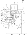
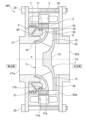
- FIG. 1 is a diagram showing one embodiment of a motor pump.
- the motor pump MP includes an impeller 1, an annular rotor 2 fixed to the impeller 1, a stator 3 arranged radially outside the rotor 2, and the impeller 1 and a bearing 5 that supports the
- the impeller 1 has a channel formed therein, and the bearing 5 is arranged outside the channel (for example, the inlet channel) of the impeller 1 .
- the motor-pump MP is a rotating machine equipped with a permanent magnet motor, but the type of motor-pump MP is not limited to this embodiment.
- the motor-pump MP may comprise an induction type motor or may comprise a reluctance type motor. If the motor pump MP has a permanent magnet type motor, the rotor 2 is a permanent magnet. If the motor-pump MP has an induction motor, the rotor 2 is a squirrel cage rotor.
- the impeller 1 is a centrifugal impeller. More specifically, the impeller 1 includes a disk-shaped main plate 10, a side plate 11 arranged to face the main plate 10, and a plurality of blades 12 arranged between the main plate 10 and the side plates 11. I have.
- the motor pump MP which includes the impeller 1 as a centrifugal impeller, has superior pressure-lifting characteristics and can generate high pressure compared to pumps such as axial flow pumps and mixed flow pumps. Furthermore, the motor pump MP in this embodiment can contribute to the rotational stability of the impeller 1 by utilizing the pressure difference generated inside.
- the side plate 11 includes a suction portion 15 formed in its central portion, and a body portion 16 connected to the suction portion 15 .
- the suction portion 15 extends in the direction of the center line CL of the motor pump MP, and the main body portion 16 extends in a direction inclined (more specifically, perpendicular) to the center line CL.
- the center line CL is parallel to the flow direction of the liquid (handled liquid) caused by the operation of the motor pump MP.
- the side plate 11 has an annular protrusion 17 extending from the outer edge 11 a of the side plate 11 (more specifically, the end of the body portion 16 ) toward the suction portion 15 .
- the main body portion 16 and the projection portion 17 are configured integrally, but the projection portion 17 and the main body portion 16 may be separate members.
- the rotor 2 has an inner diameter larger than the outer diameter of the protrusion 17 and is fixed to the outer peripheral surface 17 a of the protrusion 17 .
- the stator 3 is arranged so as to surround the rotor 2 and is housed in a stator casing 20 .
- the stator casing 20 is arranged radially outside the impeller 1 .
- the motor pump MP has a suction casing 21 and a discharge casing 22 arranged on both sides of the stator casing 20 .
- the suction casing 21 is arranged on the suction side of the impeller 1
- the discharge casing 22 is arranged on the discharge side of the impeller 1 .
- the impeller 1 , rotor 2 and bearing 5 are arranged radially inside the stator casing 20 and are arranged between the suction casing 21 and the discharge casing 22 .
- the suction casing 21 has a suction port 21a in its central portion.
- the discharge casing 22 has a discharge port 22a in its central portion. These suction port 21a and discharge port 22a are arranged in a straight line along the center line CL. Therefore, the handling liquid sucked from the suction port 21a and discharged from the discharge port 22a flows in a straight line.
- an operator inserts the through-bolt 25 into the suction casing 21 and the discharge casing 22 with the stator casing 20 sandwiched between the suction casing 21 and the discharge casing 22, and tightens the through-bolt. 25.
- the motor pump MP is assembled.
- the liquid to be handled is sucked from the suction port 21a of the suction casing 21 (see the black line arrow in FIG. 1).
- the impeller 1 raises the pressure of the liquid to be handled by its rotation, and the liquid to be handled flows in the interior of the impeller 1 in a direction perpendicular to the center line CL (that is, in the centrifugal direction).
- the handling liquid discharged to the outside of the impeller 1 collides with the inner peripheral surface 20a of the stator casing 20, and the direction of the handling liquid is changed. After that, the liquid to be handled passes through the gap between the back surface of the impeller 1 (more specifically, the main plate 10) and the discharge casing 22, and is discharged from the discharge port 22a.
- the motor pump MP has a return vane 30 arranged on the back side of the impeller 1 .
- a plurality of spirally extending return vanes 30 are provided. These multiple return blades 30 are fixed to the discharge casing 22 and face the main plate 10 of the impeller 1 .
- the return vanes 30 contribute to the conversion of the handled liquid discharged from the impeller 1 from velocity energy to pressure energy.
- the motor pump MP is divided into a suction side region Ra, a discharge side region Rb, and an intermediate region Rc between the suction side region Ra and the discharge side region Rb.
- the suction side region Ra is a region between the suction casing 21 (more specifically, the suction port 21a of the suction casing 21) and the impeller 1 (more specifically, the side plate 11 of the impeller 1).
- the discharge side region Rb is a region between the discharge casing 22 (more specifically, the discharge port 22a of the discharge casing 22) and the impeller 1 (more specifically, the main plate 10 of the impeller 1).
- a plurality of blades 12 are arranged in the intermediate region Rc.
- the rotor 2 and the bearing 5 are arranged in the suction side region Ra of the impeller 1.
- the impeller 1 includes a side plate 11 having a tapered shape that widens from the suction side region Ra toward the discharge side region Rb. Therefore, a space (dead space) is formed in the suction side region Ra of the impeller 1 .
- the motor pump MP can have a structure that effectively utilizes the dead space, resulting in a compact structure. be able to.
- the bearing 5 includes a rotating side bearing body 6 mounted on the protrusion 17 of the side plate 11 and a fixed side bearing body 7 mounted on the suction casing 21 .
- the fixed-side bearing 7 is arranged on the suction side of the rotary-side bearing 6 .
- the rotary-side bearing 6 is a rotating member that rotates with the rotation of the impeller 1
- the fixed-side bearing 7 is a stationary member that does not rotate even when the impeller 1 rotates.
- the rotation-side bearing body 6 has a cylindrical portion 6a having an outer diameter smaller than the inner diameter of the protruding portion 17, and a flange portion 6b projecting outward from the cylindrical portion 6a. Therefore, the cross section of the rotation side bearing body 6 has an L shape.
- a sealing member (for example, an O-ring) 31 is arranged between the inner peripheral surface 17b of the protrusion 17 and the cylindrical portion 6a.
- the rotation-side bearing body 6 is attached to the protrusion 17 of the impeller 1 with the sealing member 31 attached to the cylindrical portion 6a.
- the rotor 2 is arranged adjacent to the flange portion 6 b of the rotation-side bearing body 6 .
- the fixed-side bearing 7 includes a cylindrical portion 7a arranged to face the cylindrical portion 6a of the rotating-side bearing 6, and a flange portion 7b arranged to face the flange 6b of the rotating-side bearing 6. I have.
- the cross section of the fixed side bearing body 7 has an L-shape like the cross section of the rotary side bearing body 6 .
- Seal members 32 and 33 are arranged between the cylindrical portion 7 a of the fixed side bearing body 7 and the suction casing 21 . Although two sealing members 32 and 33 are arranged in this embodiment, the number of sealing members is not limited to this embodiment.
- FIG. 2 is a diagram showing the flow of liquid to be handled that passes through the gap between the rotation-side bearing and the fixed-side bearing. Since the pressure of the liquid to be handled is increased by the rotation of the impeller 1, the pressure of the liquid to be handled in the discharge side region Rb is higher than the pressure of the liquid to be handled in the suction side region Ra. Therefore, part of the liquid discharged from the impeller 1 flows back to the suction side area Ra (see the black line arrow in FIG. 2).
- part of the liquid to be handled passes through the gap between the stator casing 20 and the rotor 2, and flows through the flange portion 6b of the rotating side bearing body 6 and the flange portion 7b of the fixed side bearing body 7. flow into the gap between
- FIG. 3 is a diagram showing an embodiment of a plurality of grooves formed in the flange portion of the fixed side bearing.
- the fixed-side bearing body 7 has a plurality of grooves 40 formed in the flange portion 7b.
- the plurality of grooves 40 are formed in the surface of the flange portion 7b facing the flange portion 6b of the rotation-side bearing body 6.
- the plurality of grooves 40 are formed to generate dynamic pressure of the liquid to be handled in the gap between the flange portions 7b and 6b.
- the plurality of grooves 40 are spiral grooves that extend spirally.
- the plurality of grooves 40 may be radial grooves.
- the bearing 5 can support the thrust load of the impeller 1 without contact.
- FIG. 4A is a diagram showing an embodiment of a plurality of grooves formed in the cylindrical portion of the fixed-side bearing.
- FIG. 4A shows a plurality of grooves 41 viewed from the centerline CL direction.
- the fixed-side bearing body 7 may have a plurality of grooves 41 formed in the cylindrical portion 7a along the circumferential direction of the cylindrical portion 7a.
- the plurality of grooves 41 are evenly spaced, but may be unevenly spaced.
- the plurality of grooves 41 are formed on the surface of the cylindrical portion 7a facing the cylindrical portion 6a of the rotation-side bearing body 6, and extend parallel to the cylindrical portion 7a (that is, in the direction of the center line CL).
- each of the plurality of grooves 41 has an arcuate concave shape when viewed from the direction of the center line CL.
- the shape of the plurality of grooves 41 is not limited to this embodiment. In one embodiment, each of the plurality of grooves 41 may have a concave shape when viewed from the direction of the center line CL.
- FIGS. 4B and 4C are diagrams showing other embodiments of grooves formed in the cylindrical portion of the fixed-side bearing.
- the fixed-side bearing body 7 has an annular groove 42 formed in the cylindrical portion 7a along the circumferential direction of the cylindrical portion 7a.
- the groove 42 is formed in a portion of the cylindrical portion 7a and has a concave shape when viewed from a direction perpendicular to the direction of the center line CL (see FIGS. 4B and 4C).
- Cylindrical portions 7a are present at both ends 42a, 42a of the groove 42 in the direction of the center line CL.
- the fixed side bearing 7 (more specifically, the cylindrical portion 7a) can reliably support the impeller 1 via the rotating side bearing 6. can support.
- the length of the groove 42 in the direction of the center line CL is not particularly limited.
- the fixed side bearing body 7 has a single groove 42, but in one embodiment the fixed side bearing body 7 is arranged along the centerline CL direction. It may also have a plurality of grooves 42 formed therein.
- the size of the narrow area formed in the gap between the cylindrical portion 6a and the cylindrical portion 7a is reduced. Therefore, it is possible to reduce the viscous resistance generated in the liquid to be handled. Furthermore, by forming a plurality of grooves 41 (or grooves 42), dynamic pressure of the liquid to be handled is generated, and the bearing 5 can support the radial load of the impeller 1 without contact. The effect of reducing the viscous resistance by reducing the size of the narrow area formed between the flange portions 6b and 7b can also be achieved by providing a plurality of grooves 40 (see FIG. 3).
- the grooves 41, 42 are formed in the cylindrical portion 7a, but in one embodiment, the grooves 41, 42 are formed in the cylindrical portion 6a of the rotation-side bearing body 6. may With such a configuration, the bearing 5 can also support the radial load of the impeller 1 without contact.
- the liquid to be handled that has passed through the gap between the cylindrical portion 6a of the rotating-side bearing 6 and the cylindrical portion 7a of the fixed-side bearing 7 flows into the space between the side plate 11 of the impeller 1 and the suction casing 21. It passes through the gap in between and is returned to the suction side of the motor pump MP.
- the bearing 5 is arranged on the course of the leakage flow of the liquid to be handled. With such a configuration, part of the handled liquid flows into the minute gap between the rotating side bearing 6 and the fixed side bearing 7, and as a result, the motor pump MP suppresses leakage of the handled liquid. can be done.
- the motor pump MP has a structure that reduces the thrust load.
- FIG. 5A is a diagram showing an embodiment of a thrust load reduction structure provided on the back surface of the impeller.
- FIG. 5B is a diagram of FIG. 5A viewed from the line A arrow.
- the motor pump MP includes a thrust load reducing structure 45 provided on the back surface of the impeller 1 (more specifically, the main plate 10).
- the thrust load reducing structure 45 is a plurality of spirally extending back blades 46 attached to the main plate 10 .
- the plurality of back blades 46 can generate a load in the direction opposite to the thrust load by the rotation of the impeller 1 .
- the thrust load reduction structure 45 can reduce the thrust load generated in the motor pump MP.
- FIG. 6 is a diagram showing another embodiment of the thrust load reduction structure.
- the thrust load reduction structure 45 includes a plurality of cuts formed along the circumferential direction of the impeller 1 (more specifically, the main plate 10) and extending toward the center of the impeller 1. A notched structure may be used.
- the main plate 10 of the impeller 1 has a plurality of notches 47 formed therein. By forming the plurality of notches 47, the contact area of the liquid to be handled with the main plate 10 is reduced. As a result, the thrust load reduction structure 45 can reduce the thrust load generated in the motor pump MP.
- the embodiment shown in FIG. 5 and the embodiment shown in FIG. 6 may be combined.
- the impeller 1 always receives a thrust load from the discharge side toward the suction side. Furthermore, the bearing 5 supports the impeller 1 that generates rotational force. Therefore, the parallelism of the impeller 1 itself is maintained, and the fluctuation of the impeller 1 can be suppressed. As a result, the motor pump MP can stably continue its operation with a structure in which only the single bearing 5 is arranged in the suction side region Ra (that is, a single bearing structure).
- At least one of the impeller 1 and the bearing 5 may be made of a lightweight material.
- lightweight materials include resins and metals with low specific gravity (eg, aluminum alloys, magnesium alloys, titanium alloys, etc.). With such a structure, the weight of the motor pump MP itself can be reduced, and the bearing 5 (and the impeller 1) can be made even more compact.
- the material of the member that contacts the liquid (that is, the liquid contact member) such as the impeller 1 and the bearing 5 is not particularly limited, and can be appropriately changed to any material according to the quality of the liquid.
- the plurality of return vanes 30 can reduce the radial load generated on the impeller 1.
- the plurality of return vanes 30 are arranged at equal intervals along the circumferential direction of the discharge port 22a. With such an arrangement, the radial load is evenly distributed, and as a result the radial load generated on the impeller 1 is reduced.
- the motor pump MP includes a permanent magnet motor. Therefore, when the motor pump MP is started, a constant load acts on the bearing 5 for converting the repulsive force caused by the magnetic force into a rotational force. This load is a force generated in the rotor 2, and the bearing 5 supports this load.
- FIGS. 7A and 7B are diagrams showing a rotor that is staggered with respect to the stator.
- the impeller 1 is affected by the magnetic force generated between the rotor 2 and the stator 3.
- the rotating side bearing 6 receives a force acting in a direction to approach the stationary side bearing 7 (see the arrow in FIG. 7A). With this arrangement, it is possible to adjust (increase) the thrust load of the rotation-side bearing 6 acting on the fixed-side bearing 7 .
- FIG. 8 is a diagram showing one embodiment of a bearing having a tapered structure.
- the gap between the rotating side bearing body 6 and the fixed side bearing body 7 extends along the center line CL (that is, the central portion of the impeller 1) from the suction side to the discharge side. It has a tapered structure extending in a direction close to the .
- the rotation side bearing body 6 and the fixed side bearing body 7 respectively have inclined surfaces 50 and 51 facing each other.
- FIG. 9 is a diagram showing another embodiment of a bearing having a tapered structure.
- the bearing 5 has a center line CL (that is, the central portion of the impeller 1) where the gap between the rotating side bearing body 6 and the fixed side bearing body 7 extends from the suction side to the discharge side. It has a tapered structure extending away from the .
- the rotation side bearing body 6 and the fixed side bearing body 7 respectively have inclined surfaces 53 and 54 facing each other.
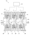
- FIG. 10 is a diagram showing a pump unit including a plurality of motor pumps.
- the pump unit PU may include a plurality of motor-pumps MP arranged in series and an inverter 60 that controls the operation of each of the plurality of motor-pumps MP.
- each of the plurality of motor pumps MP has the same structure as that shown in the above-described embodiments. Therefore, detailed description of the motor pump MP is omitted.
- the pump unit PU includes three motor-pumps MP, but the number of motor-pumps MP is not limited to this embodiment.
- the suction port 21a and the discharge port 22a of the pump unit PU are arranged in a straight line along the center line CL. Therefore, a plurality of motor-pumps MP can be continuously arranged in a straight line, and the pump unit PU can easily have a multi-stage motor-pump structure.
- each of the intermediate casings 61 , 61 has a common (that is, similar) structure to the suction casing 21 .
- the operator inserts the through bolts 25 into the suction casing 21, the intermediate casings 61, 61, and the discharge casing 22 and tightens them.
- the pump unit can be assembled.
- one inverter 60 is connected to the stators 3 of the motor pumps MP.
- the inverter 60 can independently control each of the plurality of motor pumps MP. Therefore, the operator can operate at least one motor-pump MP at any timing according to the operating conditions of the pump unit.
- FIGS. 11 and 12 are diagrams showing other embodiments of the pump unit.
- the pump unit PU comprises a plurality of motor pumps MP arranged in parallel. 11, each of the plurality of motor pumps MP is installed inside the pipe 65, although it is simply drawn. Although four motor-pumps MP are provided in FIG. 11, the number of motor-pumps MP is not limited to this embodiment. As shown in FIG. 12, three motor pumps MP may be provided.
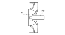
- FIG. 13A is a diagram showing a motor pump as a comparative example.
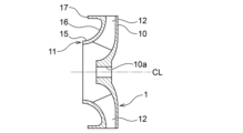
- 13B and 13C are diagrams showing another embodiment of the motor-pump.
- the motor-pump as the comparative example has a rotating shaft RS, but the motor-pump MP according to the present embodiment does not have a rotating shaft RS. Instead, the impeller 1 is provided with a rounded projection 70 located in its central portion.
- the impeller 1 has protrusions 70A with a first radius of curvature, and in the embodiment shown in FIG. 13C, the impeller 1 has a second radius different from the first radius of curvature. It has a convex portion 70B having a radius of curvature.
- the convex portions 70A and 70B may be simply referred to as the convex portion 70 without distinguishing between them.
- the convex portion 70 is arranged at the central portion of the main plate 10 and is integrally formed with the main plate 10 .
- the convex portion 70 may be a member different from the main plate 10 .
- the protrusions 70 having different curvature radii may be replaced according to the operating conditions of the motor pump.
- a tip portion 71 of the convex portion 70 has a smooth convex shape, and the liquid to be handled that flows into the impeller 1 contacts the tip portion 71 of the convex portion 70 .
- the projections 70 By providing the projections 70, the liquid to be handled is smoothly and efficiently guided to the blades 12 without obstruction of its flow.
- the motor pump since the rotating shaft RS is fixed to the impeller by the nut Nt, there is a possibility that the nut Nt (and the rotating shaft RS) may block the flow of the handled liquid. be.
- a convex portion 70A shown in FIG. 13B has a radius of curvature larger than that of the convex portion 70B shown in FIG. 13C.
- the radius of curvature of the convex portion 70 By increasing the radius of curvature of the convex portion 70, the distance between the convex portion 70 and the side plate 11 is reduced. Conversely, by decreasing the radius of curvature of the projection 70, the distance between the projection 70 and the side plate 11 is increased.
- the radius of curvature of the projections 70 in this manner the size of the flow path of the impeller 1 for the liquid to be handled can be adjusted.
- the flow path of impeller 1 shown in FIG. 13C is larger than the flow path of impeller 1 shown in FIG. 13B.
- the motor pump MP does not have a rotating shaft, the number of parts can be reduced, and the size of the flow path can be adjusted. Furthermore, the impeller 1 can have a compact size, since no rotating shaft needs to be provided. As a result, the entire motor-pump MP can have a compact size.
- the motor pump rotates the impeller 1 at high speed by its operation. If the center of gravity of the impeller 1 is displaced, the impeller 1 will rotate at high speed in an eccentric state. As a result, noise may occur, and in the worst case, the motor pump may fail.
- the operator executes a balance (dynamic balance) adjustment method for determining the position of the center of gravity of the impeller 1 to a desired position.
- a balance dynamic balance
- FIG. 13A when the rotating shaft RS is attached to the impeller, it is necessary to attach the rotating shaft RS to the test machine and rotate the impeller together with the rotating shaft RS.
- the impeller 1 is not attached with the rotating shaft RS, so the operator can perform the balance adjustment method described below.
- FIG. 14 to 18 are diagrams showing an embodiment of the balance adjustment method.
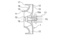
- an operator performs a step of forming a through hole 10a in the center of the impeller 1 (more specifically, the main plate 10).
- the operator inserts the shaft body 76 of the balance adjustment jig 75 into the through hole 10a.
- a shaft body 76 of the balance adjustment jig 75 corresponds to a rotating shaft.
- the worker places the fixed body 77 on the back side of the impeller 1 and fastens the shaft 76 to the fixed body 77.
- the worker rotates the impeller 1 together with the balance adjusting jig 75, determines the position of the center of gravity of the impeller 1, and executes the process of adjusting the position of the center of gravity.
- the balance adjusting jig 75 has a structure that supports the center of the impeller 1 . Therefore, the balance adjustment jig 75 may be called a center support adjustment jig.
- the operator pulls out the shaft body 76 of the balance adjustment jig 75, and then inserts the center cap 80 into the through hole 10a to close the through hole 10a. (see FIGS. 17 and 18).
- the center cap 80 has a rounded shape similar to the protrusion 70 according to the embodiment shown in FIGS. 13B and 13C. Therefore, the liquid to be handled is smoothly and efficiently guided to the blades 12 without obstruction of its flow.
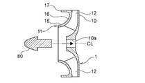
- FIG. 19 is a diagram showing another embodiment of the balance adjustment jig.
- the balance adjustment jig 75 has a structure that supports the center of the impeller 1 .
- the balance adjustment jig 85 includes a supporter 86 that supports the rotation-side bearing body 6 of the bearing 5 and a shaft portion 87 fixed to the supporter 86 .
- the balance adjusting jig 85 has a structure for supporting the end of the impeller 1 . Therefore, the balance adjustment jig 85 may be called an edge support adjustment jig.
- the supporter 86 has an annular shape with an outer diameter smaller than the inner diameter of the rotation-side bearing 6 .
- the balance adjustment jig 85 is adjusted to the rotation-side bearing.
- the impeller 1 is supported via the body 6 .
- the operator performs the step of rotating the impeller 1 together with the balance adjusting jig 85 .
- the operator determines the position of the center of gravity of the impeller 1 while rotating the impeller 1, and performs a step of adjusting the position of the center of gravity.
- the operator does not need to form the through hole 10a.
- the impeller 1 may have a convex portion 70 formed at its center position (see FIGS. 13A and 13B).
- FIG. 20 is a diagram showing another embodiment of the balance adjustment method.
- the rotor 2 includes an annular iron core 2a and a plurality of magnets 2b embedded in the iron core 2a.
- the plurality of magnets 2b are arranged at regular intervals along the circumferential direction of the rotor 2 (more specifically, the iron core 2a).
- a worker performs a step of forming a plurality of weight insertion holes 90 along the circumferential direction of the rotor 2 .
- the process of forming the weight insertion hole 90 is performed when the iron core 2a is manufactured.
- a weight insertion hole 90 is formed between adjacent magnets 2b.
- the operator executes the process of determining the center-of-gravity position of the impeller 1 to determine the current center-of-gravity position of the impeller 1 .
- the operator inserts the weight 91 into at least one of the plurality of weight-insertion holes 90 to adjust the center-of-gravity position.
- the operator when the center-of-gravity position of the impeller 1 is shifted, instead of inserting the weight 91 into the weight-insertion hole 90 , the operator inserts a weight that causes the shift of the center-of-gravity position of the impeller 1 . Excess may be removed.
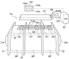
- FIG. 21A is a perspective view showing another embodiment of the pump unit.
- FIG. 21B is a plan view of the pump unit shown in FIG. 21A.
- the pump unit PU includes a plurality of (three in this embodiment) motor-pumps MP, a control device 100 that operates the plurality of motor-pumps MP at variable speeds, and and a current sensor 101 that is electrically connected and detects the current supplied to the plurality of motor pumps MP.
- the current sensor 101 may be arranged.
- the current sensor 101 include a Hall element and a CT (current transducer).
- the pump unit PU includes power lines 105 and signal lines 106 extending from a plurality of motor pumps MP, and a protective cover 107 that protects the current sensor 101, power lines 105 and signal lines 106.
- Power line 105 and signal line 106 are electrically connected to inverter 60 .
- U-phase, V-phase, and W-phase copper bars (in other words, current-carrying plates, copper plates) 108 are spanned between the plurality of motor pumps MP. connected to one Each motor pump MP has a terminal block 102 to which a copper bar 108 is connected.
- the control device 100 is electrically connected to the inverter 60 and configured to control the operation of the motor pump MP via the inverter 60 .
- Control device 100 may be arranged outside inverter 60 or inside inverter 60 .
- the control device 100 includes a signal receiving section 100a that receives a signal from the current sensor 101 through the signal line 106, a storage section 100b that stores information on the operation of the motor pump MP and an operation program, and data and storage received by the signal receiving section. and a control unit 100c that controls the operation of the motor pump MP based on the data stored in the unit.
- the pump unit PU includes one inverter 60 for a plurality of motor-pumps MP. good too.
- each of the plurality of inverters 60 controls the operation of each of the plurality of motor-pumps MP by the control device 100 .
- the motor pump MP has a compact structure that makes effective use of dead space. Therefore, by connecting the plurality of motor pumps MP in series, the pump unit PU can be operated at a high head without increasing its installation area.
- the motor pump MP is a rotating machine equipped with a permanent magnet motor. Such motors rotate uncontrolled by forcibly applying a voltage at start-up. Control of the rotation speed of the motor pump MP by the inverter 60 is immediately started, and then steady operation of the motor pump MP is started.
- the pump unit PU includes a plurality of motor pumps MP. Therefore, there is no problem if the rotational speed difference between the plurality of motor pumps MP is eliminated before the control of the rotational speed of the motor pumps MP is started. A startup failure may have occurred.
- the motor pump MP in this embodiment has a structure in which a flow path is formed inside the rotor 2, and the outer diameter of the rotor 2 is designed to be large.
- the pump unit PU can eliminate rotational speed differences among the plurality of motor pumps MP. Furthermore, in this embodiment, by using inexpensive planar magnets, the cost of the rotor 2 can be reduced compared to a general motor using curved magnets.
- the motor pump MP has a canned motor structure in which the stator 3 is housed in the stator casing 20, and the distance between the rotor 2 and the stator 3 is generally Larger than the motor. Therefore, the motor-pump MP can reduce torque ripple, which means the range of torque fluctuations, and as a result, the pump unit PU can eliminate rotational speed differences among the plurality of motor-pumps MP.
- the pump unit PU can eliminate the rotational speed difference, but it is desirable to operate the motor pump MP more stably when the motor pump MP is started and/or during steady operation.
- the multiple motor pumps MP are connected in series.
- the foreign matter may get entangled in the motor pump MP (in particular, the first motor pump MP), and as a result, the foreign matter may hinder the operation of the pump unit PU. .
- the rotational speed difference between the plurality of motor pumps MP will not be resolved.
- FIG. 22 is a diagram showing the control flow of the motor pump by the control device.
- the control device 100 electrically connected to the inverter 60 determines current values of the plurality of motor pumps MP during current operation based on the output current of the inverter 60. (More specifically, the total current value of each motor pump MP) is measured.
- the control device 100 calculates the lower limit current value based on the assumed current value during normal operation of the motor pump MP (more specifically, during start-up and steady operation), and measures the current value. The sum of the measured current values (measured current value Amax) is compared with a predetermined lower limit current value (see step S102).
- the storage unit 100b of the control device 100 stores an assumed current value of each motor-pump MP and an assumed current value of a plurality of motor-pumps MP. The storage unit 100b may calculate assumed current values of a plurality of motor-pumps MP from assumed current values of each motor-pump MP.
- the control device 100 may determine the "assumed current value assumed during normal operation".
- the "assumed current value assumed during normal operation” may be determined based on the current value during operation of a plurality of units.
- the control device 100 determines the lower limit current value based on the number of motor pumps MP.
- the lower limit current value is obtained by the following formula.
- Lower limit current value Assumed current value of a plurality of motor-pumps MP x (1-1/number of motor-pumps n) In this embodiment, since three motor pumps MP are arranged, the lower limit current value is 2 ⁇ 3 of the assumed current value.
- control device 100 compares the calculated lower limit current value and the measured current value (see step S103). More specifically, control device 100 determines whether or not the measured current value is lower than the lower limit current value (measured current value Amax>lower limit current value).
- the control device 100 determines that at least one of the plurality of motor pumps MP is abnormal (see step S104). If the measured current value has not decreased below the lower limit current value (see “NO” in step S103), control device 100 repeats steps S102 and S103.
- control device 100 may issue an alarm while continuing to operate the motor pump MP, or may stop the operation of the motor pump MP and issue an alarm. may report.
- Such a control flow may be performed when the motor pump MP is started, or when the motor pump MP is in steady operation.
- the control flow is performed when the motor-pumps MP are started, the measured current value corresponds to the starting current value when the plurality of motor-pumps MP are started, and the assumed current value is the normal start-up of the plurality of motor-pumps MP. This is the assumed current value.
- the measured current value corresponds to the operating current value during steady-state operation of the plurality of motor-pumps MP
- the assumed current value is the normal current value of the plurality of motor-pumps MP. This is the current value assumed during steady operation.
- the starting current value and the operating current value may be the same or different.
- the assumed current value assumed during normal start-up and the assumed current value assumed during normal steady operation may be the same or different.
- control device 100 may determine the assumed current value based on the flow rates on the discharge sides of a plurality of motor pumps MP.
- pump unit PU includes a flow rate sensor (not shown) that detects the flow rate of the liquid to be handled, and the flow rate sensor is electrically connected to control device 100 .
- the storage unit 100b of the control device 100 stores data indicating the correlation between the flow rate of the liquid to be handled during normal operation and the current supplied to the plurality of motor pumps MP during normal operation.
- Control device 100 determines an assumed current value based on this data, and calculates a lower limit current value based on the determined assumed current value.
- An example of the formula for calculating the lower limit current value is the above formula.
- the control device 100 compares the measured current value during steady operation of the plurality of motor pumps MP with the lower limit current value, and if the measured current value is lower than the lower limit current value, at least It is judged that an abnormality has occurred in one of them.
- control device 100 may determine the assumed current value based on the pressures on the discharge sides of a plurality of motor pumps MP.
- pump unit PU includes a pressure sensor (not shown) that detects the pressure of the liquid to be handled, and the pressure sensor is electrically connected to control device 100 .
- the storage unit 100b of the control device 100 stores data indicating the correlation between the pressure of the liquid to be handled and the current supplied to the plurality of motor pumps MP during normal operation.
- Control device 100 determines an assumed current value based on this data, and calculates a lower limit current value based on the determined assumed current value.
- An example of the formula for calculating the lower limit current value is the above formula.
- the control device 100 compares the measured current value during steady operation of the plurality of motor pumps MP with the lower limit current value, and if the measured current value is lower than the lower limit current value, at least It is judged that an abnormality has occurred in one of them.
- the pump unit PU is arranged between the first motor-pump MP (first motor-pump MP) and the second motor-pump MP (second motor-pump MP). and a current sensor 101 (second current sensor 101) arranged between the second motor pump MP and the third motor pump MP (third motor pump MP) ), and
- the control device 100 compares the measured current value Aa1 with the assumed current value assumed during normal operation of each motor pump MP (during start-up and steady operation), and the measured current value Aa1 is greater than the assumed current value. is low (Aa1 ⁇ assumed current value), it is determined that the first motor pump MP is abnormal.
- the control device 100 compares the measured current value Aa1 with the assumed current value assumed during normal operation of each motor pump MP (during start-up and steady operation), and the measured current value Aa1 is greater than the assumed current value. is large (Aa1 > assumed current value), and the value obtained by subtracting the measured current value Aa1 from the measured current value Ab (that is, Ab - Aa1) is smaller than the assumed current value ((Ab - Aa1) ⁇ assumed current value) , it is determined that an abnormality has occurred in the second motor pump MP.
- a value obtained by subtracting the measured current value Aa1 from the measured current value Ab corresponds to the measured current value Aa2.
- the controller 100 determines that the measured current value Amax is lower than the lower limit current value and determines that there is no abnormality in the first motor-pump MP and the second motor-pump MP, the third motor-pump Determine that an abnormality has occurred in the MP.
- the pump unit PU When the pump unit PU includes four motor-pumps MP connected in series, the pump unit PU is provided between the third motor-pump MP and the fourth motor-pump MP (fourth motor-pump MP). A current sensor 101 (third current sensor 101) is provided.
- the control device 100 Based on the signal sent from the third current sensor 101, the control device 100 detects the measured current value Aa1 of the first motor-pump MP, the measured current value Aa2 of the second motor-pump MP, and the measured current value Aa3 of the third motor-pump MP. (ie, the measured current value Ac) can be measured.
- control device 100 determines that the measured current value Amax is lower than the lower limit current value and determines that the first motor-pump MP, the second motor-pump MP, and the third motor-pump MP are not abnormal. , it is determined that the fourth motor pump MP is abnormal. Note that even when the pump unit PU includes five or more motor-pumps MP connected in series, the control device 100 can determine abnormality of each motor-pump MP by the same method as described above. can be done.
- the pump unit PU may control a plurality of motor-pumps MP connected in parallel.
- the control device 100 may be configured to shift the activation timing of each of the plurality of motor-pumps MP.
- the pump unit PU can form a swirling flow in the pipe 65.
- a swirling flow it is possible to remove foreign substances and air adhering to the pipe 65, and furthermore to prevent the liquid to be handled from stagnation.
- the control device 100 activates one of the plurality of motor pumps MP (first motor pump MP), and then controls the activated motor pump MP (that is, the first motor pump MP). may start the motor-pump MP (second motor-pump MP) adjacent to the . In this way, by successively activating the adjacent motor-pumps MP, the pump unit PU can form a swirling flow that revolves along the activation order of the motor-pumps MP.
- the control device 100 may start the first motor-pump MP and then start the second motor-pump MP, or may start the third motor-pump MP. After activation, the first motor-pump MP adjacent to the third motor-pump MP may be activated.
- FIG. 23 is a diagram showing another embodiment of the impeller. In this embodiment, illustration of the bearing 5 is omitted.
- the impeller 1 includes an annular protrusion 17 extending from the outer edge 11a of the side plate 11 toward the suction portion 15 (see FIG. 1).
- the side plate 11 of the impeller 1 has an annular protrusion 117 arranged radially inside the outer edge 11 a of the side plate 11 .
- the rotor 2 is arranged on an annular stepped portion formed between the outer edge portion 11 a of the side plate 11 and the protrusion 117 , and the exposed portion of the rotor 2 is covered with the cover 110 .
- Cover 110 is one of the components of motor pump MP. Examples of the cover 110 include a corrosion-resistant can, a resin coat, or a Ni-plated coat.
- the core 2a of the rotor 2 is joined to the protrusions 117 by means of adhesive, press fitting, shrink fitting, welding, or the like.
- the cover 110 is joined to the impeller 1 by means of adhesives, press fitting, shrink fitting, welding, or the like.
- FIG. 24 is a diagram showing another embodiment of the impeller.
- the impeller 1 may include an annular mounting portion 118 arranged radially outwardly of the protrusion 117 .
- the rotor 2 can be fixed to the side plate 11 more reliably.
- the exposed portion of the rotor 2 is covered with the cover 110 .
- FIG. 25 is a diagram showing a sealing member arranged between the cover and the side plate. In this embodiment, illustration of the bearing 5 is omitted. As shown in FIG. 25, by arranging sealing members (for example, O-rings) 120 and 121 between the cover 110 and the side plate 11 (more specifically, the outer edge portion 11a and the protrusion 117 of the side plate 11), the , the liquid can be reliably prevented from coming into contact with the rotor 2 .
- sealing members for example, O-rings
- the impeller 1 according to the embodiment shown in FIGS. 1 to 25 is manufactured, for example, by casting, stainless press molding, resin molding, or the like.
- the impeller 1 according to the embodiments shown in FIGS. 26 to 34 described below may also be similarly manufactured by casting, stainless steel press molding, resin molding, or the like.
- FIG. 26 is a diagram showing another embodiment of the impeller. In this embodiment, illustration of the bearing 5 is omitted. As shown in FIG. 26, the rotor 2 is fixed to the outer edge portion 11a of the side plate 11 so as to block the flow path (that is, the outlet flow path) of the impeller 1 formed between the main plate 10 and the side plate 11. It is also in this embodiment, the rotor 2 is arranged in the suction side area Ra.
- the rotor 2 is not covered with a cover 110, and is made of a corrosion-resistant material. Also in the above-described embodiment, the rotor 2 does not necessarily need to be covered with the cover 110, and may be made of a material having corrosion resistance. In one embodiment, rotor 2 may be covered with cover 110 .
- the handled liquid passing through the outlet channel collides with the inner peripheral surface of the rotor 2, and the direction of the handled liquid is changed. After that, the liquid to be handled passes through the gap between the main plate 10 and the discharge casing 22 and is discharged from the discharge port 22a.
- the rotor 2 and the bearing 5 are arranged in the suction side region Ra of the impeller 1, so the motor pump MP has a compact structure.
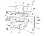
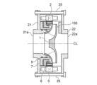
- FIG. 27 is a diagram showing another embodiment of the motor pump.
- the motor pump MP includes a first impeller 1A arranged on the side of the suction port 21a, a second impeller 1B arranged on the side of the discharge port 22a, the first impeller 1A and the second impeller 1B. and a communication shaft 126 connected to the impeller 1B.
- the rotor 2 is fixed to the first impeller 1A, and the stator 3 is arranged radially outside the rotor 2 .
- the bearing 5 supports the first impeller 1A, and the second impeller 1B is supported by the bearing 5 via the communication shaft 126. As shown in FIG.
- the motor pump MP has an intermediate casing 125 arranged between the first impeller 1A and the second impeller 1B.
- the intermediate casing 125 is an annular partition separating the discharge side of the first impeller 1A and the suction side of the second impeller 1B.
- intermediate casing 125 is fixed to stator casing 20 .
- the motor pump MP has two impellers 1, but the number of impellers 1 is not limited to this embodiment.
- the motor pump MP may have multiple intermediate casings 125 depending on the number of impellers 1 .
- the motor-pump MP may comprise a plurality of impellers 1 including at least a first impeller 1A and a second impeller 1B.
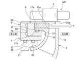
- FIG. 28 is a diagram showing another embodiment of the motor pump.
- the motor pump MP further includes a discharge side bearing 128 that rotatably supports the communication shaft 126 and is arranged on the discharge side of the second impeller 1B.
- the discharge side bearing 128 is attached to the discharge casing 22, and seal members (for example, O-rings) 127A and 127B are arranged in a gap between the discharge side bearing 128 and the discharge casing 22.
- seal members for example, O-rings
- the motor-pump MP may comprise a plurality of impellers 1 including at least a first impeller 1A and a second impeller 1B.
- the discharge casing 22 has a channel 129 communicating with the discharge port 22a.
- the flow path 129 is arranged radially outside the communication shaft 126 .
- the handling liquid discharged from the second impeller 1B is discharged to the outside through the flow path 129 and the discharge port 22a.
- the first impeller 1A and the second impeller 1B are supported not only by the bearing 5 but also by the discharge side bearing 128.
- the discharge side bearing 128 is a radial bearing.
- FIG. 29 is a diagram showing another embodiment of the motor pump.
- the motor pump MP may include a communicating shaft 126 to which one impeller 1 is fixed, and a discharge side bearing 128 that rotatably supports the communicating shaft 126 .
- FIG. 30 is a diagram showing a motor-pump in which various components can be selected according to operating conditions.
- the horizontal axis indicates the flow rate
- the vertical axis indicates the head.
- the motor pump MP is configured such that optimum component parts can be selected according to various operating conditions (that is, the magnitude of the flow rate and the magnitude of the head).
- the motor pump MP can be selected from a plurality (four in this embodiment) of different configurations (MPA to MPA in FIG. MPD).
- the motor pump MP includes a plurality of impellers 1 having different sizes, a plurality of rotors 2 fixed to the plurality of impellers 1 and having different lengths, and a plurality of rotors 2 having different lengths. and a plurality of stator casings 20 each containing the plurality of stators 3 and having a length corresponding to the length of the plurality of stators 3. ing.
- the size of the motor capacity of the motor pump MP depends on the length Lg of the stator 3.
- the size of the head of the motor pump MP depends on the size of the diameter D1 of the impeller 1 .
- the flow rate of the motor pump MP depends on the size of the outlet channel B2 of the impeller 1 .
- a plurality of impellers 1 are provided with a plurality of side plates 11 having the same diameter and a plurality of main plates 10 having different diameters.
- the diameter D1 of the impeller 1 corresponds to the diameter of the main plate 10 .
- Motor pump MPA has a higher head capacity than motor pump MPB (ie, D1A>D1B).
- Motor pump MPB has a higher flow capacity than motor pump MPA (ie, B2B>B2A).
- Motor pump MPC has a larger motor displacement than motor pump MPB (ie, LgC>LgB). Motor pump MPC has a higher head capacity than motor pump MPB (ie, D1C>D1B).
- the outlet channel B2B of the impeller 1 of the motor pump MPB has the same size as or larger than the outlet channel B2C of the impeller 1 of the motor pump MPC (i.e., B2B ⁇ B2C ).
- the motor pump MPC has a higher head capacity than the motor pump MPD (ie, D1C>D1D).
- Motor pump MPD has a higher flow capacity than motor pump MPC (ie, B2D>B2C).
- the inner diameter D2 and the outer diameter D3 of the stator casing 20 are the same for all motor pumps MP. Therefore, the operator prepares component parts having different sizes according to the pumping capacity and flow capacity, and selects the optimum component part from a plurality of component parts based on the operating conditions of the motor pump MP. can be done.
- stator casing 20 By making the inner diameter D2 and the outer diameter D3 of the stator casing 20 the same, components that are independent of the lift and flow capabilities (e.g., the bearing 5, the suction casing 21, and the discharge casing 22) do not have to be sized. , the pump unit PU can easily change its performance.
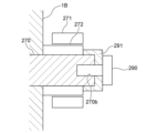
- FIG. 31A is a cross-sectional view of a motor pump according to another embodiment
- FIG. 31B is a diagram of the motor pump shown in FIG. 31A viewed from the axial direction.
- the motor pump MP may include a swivel stop (in other words, false stop) 130 arranged on the back side of the impeller 1 .
- swivel stop 130 is arranged in the embodiment shown in FIG. 31B, at least one swivel stop 130 may be arranged.
- the swivel stop 130 is fixed to the discharge casing 22 and faces the main plate 10 of the impeller 1 .
- the swirl stop 130 can prevent swirling of the liquid discharged from the impeller 1 between the impeller 1 and the discharge casing 22 .
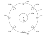
- FIG. 32A is a sectional view of a motor pump according to another embodiment
- FIG. 32B is a front view of a suction casing of the motor pump shown in FIG. 32A.
- the motor pump MP includes a suction casing 141 and a discharge casing 142 having flat flange shapes.
- the suction port 21a of the suction casing 21 protrudes from the outer surface of the suction casing 21, and similarly, the discharge port 22a of the discharge casing 22 protrudes from the outer surface of the discharge casing 22.
- the suction casing 141 has a flat flange shape
- the suction port 141 a is formed on the same plane as the outer surface of the suction casing 141 .
- the discharge casing 142 has a flat flange shape
- the discharge port 142 a is formed on the same plane as the outer surface of the discharge casing 142 .
- connection pipe 140 connected to the motor pump MP can be directly connected to the suction casing 141 .
- connection pipe 140 may be directly connected to the discharge casing 142 having a flat flange shape.
- connection pipe 140 connects the connection pipe 140 and the suction casing 141, and the number of parts for connecting the pipe (not shown) to the motor pump MP can be reduced. .
- the connecting member is a member that is expected to leak liquid, it is possible to reliably prevent liquid leakage by eliminating the connecting member.
- a sealing member for example, O-ring or gasket
- O-ring or gasket is arranged between the connecting pipe 140 and the suction casing 141 .
- An insertion hole 141b into which a fastener 150 for fastening the connecting pipe 140 and the suction casing 141 is inserted is formed on the radially outer side of the suction port 141a of the suction casing 141 .
- the connection pipe 140 has a through hole 140a communicating with the insertion hole 141b. An operator can fasten connection pipe 140 and suction casing 141 to each other by inserting fastener 150 into through hole 140a and insertion hole 141b.
- a bolt accommodating portion 142b for accommodating the head portion 25a of the through bolt 25 is formed on the radially outer side of the discharge port 142a of the discharge casing 142.
- the suction casing 141 may have a bolt accommodation portion corresponding to the bolt accommodation portion 142b. That is, at least one of the suction casing 141 and the discharge casing 142 has a bolt accommodating portion that accommodates the head portion 25 a of the through bolt 25 .
- FIG. 33 is a diagram showing a pump unit with motor pumps connected in series.
- the motor pump MP shown in FIGS. 32A and 32B includes a suction casing 141 and a discharge casing 142 having a flat flange shape.
- the casings 142 can be in surface contact with each other.
- the suction casing 141 and the discharge casing 142 that are in surface contact with each other correspond to an intermediate casing.
- a sealing member for example, an O-ring or a gasket is arranged between the suction casing 141 and the discharge casing 142 that are in surface contact with each other.
- the motor pump MP includes simple main components (that is, the impeller 1, the rotor 2 and the stator 3, and the bearing 5), and is compact and lightweight. Therefore, by using the through-bolts 25, the plurality of motor pumps MP arranged in series can be easily and integrally fastened.
- the suction casing 141 and the discharge casing 142 are brought into surface contact with each other, it is possible to improve the thermal conductivity of the pump unit PU and achieve temperature equilibrium among the plurality of motor pumps MP. As a result, the pump unit PU can stably operate.
- FIG. 34 is a diagram showing another embodiment of the impeller.
- the impeller 1 is a centrifugal impeller. More specifically, the impeller 1 has a main plate 10 extending perpendicularly to the direction of the centerline CL, and the liquid pressurized by the impeller 1 is discharged perpendicularly to the centerline CL.
- the impeller 1 is a mixed flow impeller. More specifically, the impeller 1 includes a main plate 160 that is inclined at a predetermined angle with respect to the direction of the center line CL. The main plate 160 is inclined from the suction side toward the discharge side, and the liquid pressurized by the impeller 1 is discharged obliquely outward with respect to the center line CL.
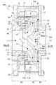
- FIG. 35 is a diagram showing another embodiment of the motor pump.
- the motor pump MP includes a rotor holder 200 that holds the rotor 2, and the impeller 1, which is a press-molded product, to which the rotor holder 200 is fixed. Also in this embodiment, the rotor 2 and the bearing 5 are arranged in the suction side region of the impeller 1 (see FIG. 1).
- the impeller 1 includes a main plate 10, a side plate 11, and a plurality of blades 12, and each of the main plate 10, the side plate 11, and the blades 12 is made of a metal material having excellent extensibility. It is a molded product. An example of such metal material is stainless steel.
- the main plate 10, side plates 11 and wings 12 are separately press formed and joined after forming.
- the weight of the entire impeller 1 can be reduced.
- Such weight reduction of the impeller 1 contributes to reduction (or needlessness) of balance (dynamic balance) adjustment for determining the position of the center of gravity of the impeller 1 to a desired position.
- the distance between the main plate 10 and the side plate 11 can be reduced, and as a result, the motor pump MP can be made even more compact.
- the rotor holder 200 prevents corrosion of the rotor 2 due to contact of the rotor 2 with the handling liquid.
- the rotor holder 200 includes a press-molded annular housing portion 201 that houses the rotor 2 , and an annular closing plate 202 that closes the housing portion 201 .
- the accommodating portion 201 has an annular concave shape and is arranged concentrically with the impeller 1 around the center line CL.
- the housing part 201 may be manufactured by deep drawing.
- the accommodation portion 201 is fixed (joined) to the side plate 11 of the impeller 1 .
- the housing 201 is welded to the side plate 11 .
- the impeller 1 and the housing portion 201 are preferably made of the same material.
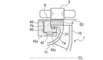
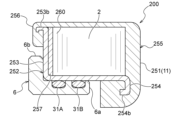
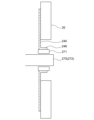
- FIG. 36 is an enlarged view of the rotor holder.
- the rotor holder 200 is arranged between the storage portion 201 and the closure plate 202 in order to prevent the liquid to be handled from entering through the gap between the storage portion 201 and the closure plate 202.
- a sealed member (eg, an O-ring) 205 is provided. The sealing member 205 fixes the closing plate 202 to the housing portion 201 by its elastic force.
- the closure plate 202 may be inserted into the rotor holder 200 by a mechanical insertion method.
- a mechanical insertion method is press-fitting of the closing plate 202 into the rotor holder 200 .
- the closing plate 202 may be inserted into the thermally expanded rotor holder 200 after heating the rotor holder 200 (shrink fitting). In this case, it is desirable to magnetize the rotor 2 after the closing plate 202 is inserted into the rotor holder 200 in order to reduce the thermal influence (that is, thermal demagnetization) on the magnetic force of the rotor 2 .
- the closing plate 202 may be inserted into the rotor holder 200 by cooling fit.
- the closure plate 202 may be inserted into the rotor holder 200 with an adhesive.
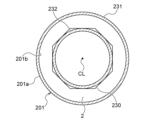
- the housing portion 201 of the rotor holder 200 includes an outer annular portion 231, an inner annular portion 232 arranged radially inside the outer annular portion 231, and an annular rear portion connecting the outer annular portion 231 and the inner annular portion 232. 233 and .
- the rotation-side bearing 6 is attached to the rotor holder 200, and the fixed-side bearing 7 is arranged on the suction side of the rotation-side bearing 6 (see FIG. 35).
- Seal members 31A and 31B are arranged between the inner annular portion 232 and the cylindrical portion 6a of the rotation-side bearing body 6. As shown in FIG. Although two sealing members are arranged in this embodiment, the number of sealing members is not limited to this embodiment.
- the inner annular portion 232 is processed smoothly in the press molding process of the rotor holder 200. In this way, by performing the press molding process, a new additional process for bringing the seal members 31A and 31B into close contact with the inner annular portion 232 can be omitted.
- the housing portion 201 (more specifically, the outer annular portion 231 and the inner annular portion 232 ) extends parallel to the cylindrical portion 6 a of the rotation-side bearing body 6 , and the cylindrical portion 6 a extends along the inner annular portion 232 of the rotor holder 200 . is located radially inward of the The flange portion 6 b of the rotation-side bearing 6 extends parallel to the closing plate 202 and is arranged adjacent to the closing plate 202 .
- the flange portion 6b of the rotation-side bearing 6 adjacent to the closing plate 202 can limit the movement of the closing plate 202. As shown in FIG.
- the rotor holder 200 is provided with a filler (for example, grease, potting material, adhesive, etc.) filled in the housing portion 201 in order to reduce the amount of air expansion in the housing portion 201. good too.
- a filler for example, grease, potting material, adhesive, etc.
- the housing portion 201 has an outer surface 201a that contacts the rotation-side bearing body 6, an inner surface 201b that contacts the rotor 2, and corner surfaces 201c formed at corners of the inner surface 201b.
- the corner surfaces 201c are smoothly curved surfaces.
- the rotor 2 has sharp corners because it is manufactured by stacking laminated cores that are stamped iron plates.
- the sharp corners of the rotor 2 come into contact with the smooth corner surface 201c, and the rotor 2 as a whole cannot be brought into close contact with the back surface portion 233. .
- the operator may not be able to reliably position the rotor 2 with respect to the rotor holder 200 and may not be able to stably house the rotor 2 in the rotor holder 200 .
- the rotor holder 200 has a spacer 203 arranged between the housing portion 201 and the rotor 2 .
- spacer 203 is a shim placed between rear portion 233 and rotor 2 . Arranging the spacer 203 can prevent the rotor 2 from contacting the corner surface 201c.
- the rotor 2 is housed in the rotor holder 200 in close contact with the spacer 203 , so the operator can reliably position the rotor 2 with respect to the rotor holder 200 . With such a configuration, the operator can stably house the rotor 2 in the rotor holder 200 .
- FIG. 37 is a diagram showing another embodiment of the spacer.
- the rotor holder 200 may include spacers 210 arranged between the housing portion 201 and the rotor 2 .
- the spacers 210 are projections protruding from the rear portion 233 of the rotor holder 200.
- FIG. 37 is a diagram showing another embodiment of the spacer.
- the rotor holder 200 may include spacers 210 arranged between the housing portion 201 and the rotor 2 .
- the spacers 210 are projections protruding from the rear portion 233 of the rotor holder 200.
- the method of fastening the rotor 2 to the rotor holder 200 includes, for example, a fastening method using an adhesive, a fastening method using shrink fitting, and a fastening method using cooling fitting.
- a fastening method for example, shrink fitting, cooling fitting, etc.
- the dimensions of the rotor 2 and the rotor holder 200 must be determined appropriately. . Therefore, it is preferable to adopt a fastening method at room temperature as a simple fastening method.
- FIG. 38 is a diagram showing the rotor inserted into the rotor holder.
- the inner surface 230 of the rotor 2 that contacts the inner annular portion 232 has a polygonal shape (octagonal in this embodiment). Since the inner surface 230 of the rotor 2 has a polygonal shape, when the rotor 2 is inserted into the rotor holder 200 at room temperature, the inner annular portion 232 of the rotor holder 200 is positioned so that the inner surface 230 of the rotor 2 can be in line contact.
- Such contact can prevent the entire rotor 2 from contacting the inner annular portion 232 of the rotor holder 200 . Therefore, even if the rotor 2 is press-fitted into the rotor holder 200, the contact area of the rotor 2 with the rotor holder 200 can be reduced, and as a result, deformation of the rotor holder 200 can be prevented. .
- FIG. 39 is a diagram showing the rotor inserted into the rotor holder.
- the inner annular portion 232 may have a plurality of protrusions 235 formed at the contact portion with the rotor 2 .
- the protrusions 235 of the inner annular portion 232 face the inner surface 230 of the rotor 2 and the rotor 2 is in contact with the protrusions 235 .
- the contact area of the rotor 2 with the rotor holder 200 can be reduced, and as a result, deformation of the rotor holder 200 can be prevented.
- the motor pump MP includes a stator casing 20 that accommodates the stator 3 and is integrally molded with the stator 3 with resin.
- the stator 3 includes a stator core 3a and coils 3b wound around the stator core 3a with an insulating material 220 interposed therebetween.
- the insulating material 220 include insulating paper and resin.
- the resin forming the stator casing 20 is made of a material (similar to the potting material) having insulating properties and excellent thermal conductivity.
- the motor pump MP includes a motor frame 221 that covers the outer peripheral surface of the stator casing 20 and contacts the stator 3 .
- Motor frame 221 has a passage hole 242 through which power line 105 and signal line 106 extending from coil 3b pass.
- the motor frame 221 is made of a material with excellent thermal conductivity (for example, metal material). In this way, the stator 3 is covered with the stator casing 20 with excellent thermal conductivity and is in contact with the motor frame 221 with excellent thermal conductivity. Therefore, the heat generated from the coils 3b of the stator 3 is radiated outside through the stator casing 20 and the motor frame 221. As shown in FIG.
- a sealing member for example, an O-ring
- the stator casing 20 has seal grooves 229 in which seal members 241 are mounted.
- the stator casing 20 is molded by pouring resin into a mold. By forming protrusions corresponding to the seal grooves 229 in the mold in advance, it is possible to omit the step of newly forming the seal grooves 229 after the stator casing 20 is manufactured.
- the suction casing 21 and the discharge casing 22 may be formed with seal grooves (not shown) in which the seal members 241 are mounted.
- stator casing 20, the return blades 30, and the partition plate 240 fixed to the return blades 30 are integrally molded members manufactured by resin molding.
- Return vane 30 may have a unique non-linear shape as a flow path.
- the stator casing 20, the return blades 30, and the partition plate 240 can be integrally manufactured easily in large quantities by adopting resin molding in which resin is poured into a mold.
- the stator casing 20 may cover the stator core 3a and the potting material-covered coils 3b in order to improve heat dissipation from the coils 3b.
- the potting material By covering the coil 3b with the potting material in this way, the potting material enters between the wire members forming the coil 3b, so that the heat dissipation of the coil 3b can be improved.
- the heat dissipation of the stator 3 can be further improved.
- An example of the resin constituting the stator casing 20 is a two-liquid mixture curing type resin (eg, dicyclopentadiene resin) or a heat curing type resin (eg, epoxy resin) having excellent fluidity at room temperature.
- the strength of the stator casing 20 can be improved by incorporating fiber as an additive into the resin.
- the improvement of the thermal conductivity of the stator casing 20 can be realized by mixing a material with high thermal conductivity as an additive. Both these fibers and materials with high thermal conductivity may be mixed as additives in the resin forming the stator casing 20 .
- FIG. 40 is a diagram showing another embodiment of the impeller.
- the motor pump MP includes an impeller 1 that is a resin molded product integrally molded with a rotor holder 200 .
- the impeller 1 is made of resin in which a main plate 10, side plates 11, and blades 12 are integrally molded.
- the strength of the impeller 1 can be improved by mixing fibers as additives into the resin.
- the rotor holder 200 includes a resin-molded annular accommodating portion 251 that accommodates the rotor 2 , and a ring holder 252 that closes the accommodating portion 251 .
- the housing portion 251 of the impeller 1 and the rotor holder 200 is integrally made of resin.
- the ring holder 252 is made of press-molded corrosion-resistant material (eg, stainless steel).
- the ring holder 252 and rotor 2 are fastened by a mechanical method such as shrink fitting, cooling fitting, or press fitting. In one embodiment, the ring holder 252 and rotor 2 may be glued together.
- the inner surface 230 of the rotor 2 that contacts the ring holder 252 may have a polygonal shape in order to reduce the press-fit load of the rotor 2 (see FIG. 38). (see FIG. 39), and the ring holder 252 may have a plurality of projections 235 formed at the contact portion with the rotor 2 (see FIG. 39).
- FIG. 41 is an enlarged view of the rotor holder.
- the ring holder 252 includes a ring portion 253 having an L-shaped cross section and a bent portion 254 bent from the ring portion 253 .
- a ring portion 253 of a ring holder 252, which is a press-molded product, has a smooth angular surface 257 formed at its bent portion.
- the rotor 2 and the bearing 5 are arranged in the suction side region of the impeller 1 (see FIG. 1).
- the rotation-side bearing 6 is attached to the ring holder 252
- the fixed-side bearing 7 is arranged on the suction side of the rotation-side bearing 6 .
- the seal members 31A and 31B are arranged between the ring portion 253 of the ring holder 252 and the cylindrical portion 6a of the rotation-side bearing body 6. As shown in FIG. Also in this embodiment, since the ring portion 253 is press-molded, a new additional process for bringing the seal members 31A and 31B into close contact with the ring portion 253 can be omitted.
- the rotor 2 has sharp corners. Therefore, even if the rotor 2 is mounted on the ring holder 252 , the sharp corners of the rotor 2 will come into contact with the smooth corner surface 257 , and as a result, the operator will have to remove the rotor 2 from the rotor holder 200 . It may not be possible to store stably in
- the rotor holder 200 has a spacer 260 arranged between the ring holder 252 and the rotor 2 .
- spacer 260 is a shim placed between ring holder 252 and rotor 2 .
- spacer 260 may be a protrusion (not shown) protruding from ring holder 252 (see FIG. 37).
- the ring holder 252 and the rotor 2 attached to the ring holder 252 are set in the mold, and the resin is poured into the mold.
- the resin forming the housing portion 251 of the rotor holder 200 wraps the rotor 2 , and as a result, the housing portion 251 seals the rotor 2 .
- the resin that is poured into the mold is hot. Therefore, when the rotor 2 mounted on the ring holder 252 is brought into contact with high-temperature resin, the rotor 2 is thermally demagnetized. Therefore, it is necessary to magnetize the rotor 2 after manufacturing the rotor holder 200 .
- the housing portion 251 of the rotor holder 200 and the impeller 1 are integrally molded members manufactured by resin molding.
- Impeller 1, like return vane 30, may have a unique non-linear shape as a flow path. According to the present embodiment, by adopting resin molding in which resin is poured into a mold, it is possible to integrally mass-produce the accommodating portion 251 of the rotor holder 200 and the impeller 1 easily.
- the ring holder 252 has an anti-rotation structure formed at a connecting portion with the accommodating portion 251 . Rotational torque of the rotor 2 is transmitted to the impeller 1 by driving the motor pump MP. Since the ring holder 252 has a detent structure, the ring holder 252 does not rotate relative to the housing portion 251 even when the impeller 1 rotates. A specific configuration of the anti-rotation structure will be described below.
- the housing portion 251 includes a main body portion 255 surrounding most of the rotor 2 and a bent portion 256 bent from the main body portion 255 .
- the ring portion 253 of the ring holder 252 has an embedding hole 253a in which a portion of the accommodating portion 251 (more specifically, the bent portion 256) is embedded.
- a plurality of embedding holes 253 a are formed along the circumferential direction of the ring holder 252 .
- the ring holder 252 and the accommodating portion 251 are firmly fastened to each other. This embedding is performed by pouring resin into a mold when the rotor holder 200 is manufactured.
- the bent portion 254 of the ring holder 252 has an embedding hole 254a in which a portion of the body portion 255 of the housing portion 251 is embedded.
- a plurality of embedding holes 254 a are formed along the circumferential direction of the ring holder 252 .
- FIG. 42 is a diagram showing another embodiment of the anti-rotation structure.
- the anti-rotation structure may be bent portions 253b and 254b bent in a U-shape. More specifically, the ring portion 253 of the ring holder 252 has a U-shaped bent portion 253b, and similarly, the bent portion 254 has a U-shaped bent portion 254b. ing.
- the ring holder 252 and the accommodating portion 251 are also firmly fastened to each other with such a structure. Note that the embodiment shown in FIG. 41 and the embodiment shown in FIG. 42 may be combined.
- the anti-rotation structure may be a gear-shaped notch (not shown) formed in each of the ring portion 253 and the bent portion 254 .
- a plurality of cuts are formed along the circumferential direction of the ring holder 252 .
- a primer is applied to the surface of the ring holder 252 in advance to remove oxides from the surface of the ring holder 252. good too.
- the stator casing 20 also has the same structure as the stator casing 20 according to the embodiment shown in Figs. 35 to 39. More specifically, the motor pump MP includes a stator casing 20 housing the stator 3 and integrally formed with the stator 3 by resin molding; a motor frame 221 in contact with 3;
- FIG. 43 is a diagram showing another embodiment of the motor pump.
- constituent elements that are the same as or correspond to those in the above-described embodiment are denoted by the same reference numerals, and overlapping descriptions are omitted.
- the motor pump MP includes a plurality of impellers including at least a first impeller 1A arranged on the side of the suction port 21a and a second impeller 1B arranged on the side of the discharge port 22a. 1.
- at least one impeller 1 may be arranged between the first impeller 1A and the second impeller 1B.
- a rotor holder 200 that holds the rotor 2 is fixed to the first impeller 1A, and a stator 3 housed in a resin stator casing 20 is arranged outside the rotor 2 in the radial direction.
- the rotor 2 housed in the rotor holder 200 is fixed to the first impeller 1A, so the rotational force of the rotor 2 acts on the first impeller 1A.
- the rotational force acting on the first impeller 1A is transmitted through the communication shaft 270 to the second impeller 1B. In this way, since the first impeller 1A receives all the rotational force of the rotor 2, the load acting on the first impeller 1A increases, and the first impeller 1A may be damaged.
- the first impeller 1A has a higher strength than the other impellers 1 (in this embodiment, the second impeller 1B). Furthermore, in order to achieve a high head of the motor pump MP according to this embodiment, it is desirable that the first impeller 1A has high strength.
- the motor pump MP having a plurality of impellers 1 desirably has not only a compact structure but also a structure with high strength. With such a structure, the motor pump MP can be stably operated.
- the motor pump MP according to this embodiment not only has a compact structure, but also has a structure that allows stable operation.
- the structure of the motor pump MP will be described below with reference to the drawings.
- the first impeller 1A is supported by the first bearing 5, and a communication shaft 270 is connected to the first impeller 1A.
- the second impeller 1B is connected to the communication shaft 270.
- the motor pump MP includes an intermediate casing 275 arranged between the first impeller 1A and the second impeller 1B, to which a liner ring 276 is connected.
- the liner ring 276 is a ring member that suppresses backflow of the handled liquid sucked into the second impeller 1B.
- the intermediate casing 275 is composed of a member separate from the stator casing 20, but the intermediate casing 275 and the stator casing 20 may be composed of the same member.
- the return vanes 30 fixed to the intermediate casing 275 also serve as guide vanes that guide the liquid discharged from the first impeller 1A to the second impeller 1B.
- the return vanes (and the guide vanes) 30 efficiently convert the flow velocity of the liquid to be handled generated by the centrifugal force of the impeller 1A of the first impeller 1A into pressure and guide it to the liquid inlet of the first impeller 1B. can be done.
- the discharge casing 22 integrally includes the return vane 30 and a partition plate 245 fixed to the return vane 30 . That is, the discharge casing 22, the return vane 30, and the partition plate 245 are integrally molded members.
- the discharge casing 22, the return vane 30, and the partition plate 245, which are integrally constructed, may be integrally constructed by resin molding. In one embodiment, the discharge casing 22, return vanes 30, and divider plate 245 may be separate members.
- the return vanes 30 fixed to the discharge casing 22 also play the same role as the return vanes 30 fixed to the intermediate casing 275 .
- FIG. 44 is a diagram showing another embodiment of the motor pump.
- the rotor holder 200 has the same structure as the rotor holder 200 according to the embodiment shown in FIG.
- the rotor holder 200 may have a structure similar to the rotor holder 200 according to the embodiment shown in FIG.
- FIG. 45 is an enlarged view of the first impeller and the second impeller.
- the boss portion 281 of the first impeller 1A has a larger size than the boss portion 282 of the second impeller 1B.
- the boss portion 281 is a connection portion with the communication shaft 270 of the first impeller 1A
- the boss portion 282 is a connection portion with the communication shaft 270 of the second impeller 1B.
- the length L1 of the boss portion 281 in the direction of the center line CL is longer than the length L2 of the boss portion 282 in the direction of the center line CL.
- the load acting on the first impeller 1A as the rotor 2 rotates is greater than the load acting on the second impeller 1B.
- the boss portion 281 of the first impeller 1A has a larger size than the boss portion 282 of the second impeller 1B. can take enough power. As a result, the motor pump MP can prevent damage to the first impeller 1A.
- the motor pump MP has a sleeve 280 that forms a predetermined distance between the first impeller 1A and the second impeller 1B.
- the sleeve 280 is arranged between the first impeller 1A and the second impeller 1B. By arranging the sleeve 280, the operator can easily manage the distance between the first impeller 1A and the second impeller 1B.
- Each of the first impeller 1A and the second impeller 1B has a power transmission structure (key structure, double chamfer structure, spline structure, etc.) and is connected to the communication shaft 270 by such structure.
- a power transmission structure key structure, double chamfer structure, spline structure, etc.
- each of the first impeller 1A and the second impeller 1B is fixed to the communicating shaft 270 by a fastener (for example, a nut) 273 fastened to the communicating shaft 270.
- a sleeve 280 is arranged between the first impeller 1A and the second impeller 1B, and a rotation-side bearing 272 (described later) is arranged between the fastener 273 and the second impeller 1B. are placed.
- the sleeve 280 is pressed against the first impeller 1A, and the rotation-side bearing body 272 is pressed against the second impeller 1B.
- the first impeller 1A is sandwiched between the tip portion 270a of the communicating shaft 270 and the sleeve 280, and the second impeller 1B is sandwiched between the sleeve 280 and the rotation-side bearing 272.
- the first impeller 1A and the second impeller 1B are firmly fixed to the communication shaft 270. As shown in FIG.
- the distal end portion 270a of the communication shaft 270 is arranged on the suction side, and the fastener 273 is arranged on the discharge side.
- the distal end 270a of the communicating shaft 270 may have a hexagonal head or a hexagonal hole. With such a structure, the operator can firmly fasten the fastener 273 to the communicating shaft 270 while the tip portion 270a is fixed.
- FIG. 46 is a diagram showing another embodiment of the connection structure between the first impeller, the second impeller, and the communication shaft.
- the motor pump MP includes collets 285 and 286 that fasten the first impeller 1A and the second impeller 1B to the communicating shaft 270, respectively. Since the collets 285 and 286 have the same structure, the structure of the collet 285 will be described below.
- the collet 285 is a tubular member having a tapered shape and has a notch (not shown) extending in the direction of the center line CL.
- the motor pump MP includes a second bearing (slide bearing) 277 that rotatably supports the communication shaft 270 and is arranged behind the second impeller 1B.
- the second bearing 277 includes a rotation-side bearing body 272 arranged on the communication shaft 270 side and a fixed-side bearing body 271 arranged on the discharge casing 22 side.
- the rotation-side bearing 272 is a rotation-side cylindrical body attached to the communicating shaft 270, and the fixed-side bearing 271 is attached to the discharge casing 22 and surrounds the rotation-side bearing 272 as a rotation-side cylindrical body. It is a side cylinder.
- a partition plate 245 of the discharge casing 22 has a bearing support portion 246 that supports the fixed side bearing body 271 .
- the fixed-side bearing body 271 is fixed to the bearing support portion 246 .
- a slight gap is formed between the fixed side bearing body 271 and the rotary side bearing body 272 .
- Ceramic or resin can be mentioned as an example of the material of the second bearing 277 .
- the communication shaft 270 is supported not only by the first bearing 5 fixed to the first impeller 1A but also by the second bearing 277.
- a communication shaft 270 to which a plurality of impellers 1 are connected has a longer length in the direction of the center line CL.
- the motor pump MP including the first bearing 5 and the second bearing 277 suppresses shaft vibration of the communication shaft 270 due to the lengthening of the communication shaft 270, and as a result, can stably operate.
- the first impeller 1A and the communication shaft 270 are fastened (step 1).
- the intermediate casing 275 (see FIGS. 43 and 44) is inserted into the communicating shaft 270 (step 2), and the sleeve 280 is inserted into the communicating shaft 270 (step 3).
- the second impeller 1B is inserted into the communication shaft 270, and the second impeller 1B and the communication shaft 270 are fastened (Step 4).
- the rotation-side bearing body 272 is inserted into the communication shaft 270 (step 5), and the discharge casing 22 is fastened to the stator casing 20 (step 6).
- the fastener 273 is fastened to the communication shaft 270 (step 7).
- the worker may perform step 7 after performing step 5, and then perform step 6.
- the communication shaft 270 is inclined, and as a result, the position of the communication shaft 270 may deviate from the direction of the center line CL.
- the worker attaches the discharge casing 22 and fastens the fastener 273 to the communicating shaft 270 while confirming the positional relationship between the rotating side bearing body 272 and the fixed side bearing body 271 .
- the motor pump MP is a straight type motor pump in which the suction port 21a and the discharge port 22a are aligned. It can be fastened to the shaft 270 .
- FIG. 47 is a diagram showing another embodiment of the fastener.
- fastener 290 has a smaller diameter than rotating bearing 272 .
- fastener 290 may have the same diameter as rolling bearing 272 .
- a spacer 291 is arranged between the fastener 290 and the communication shaft 270 . By inserting the fastener 290 into the screw hole 270b formed in the end of the communicating shaft 270, the spacer 291 presses the rotation side bearing body 272 against the second impeller 1B. According to this embodiment, even if the fixed-side bearing body 271 is inserted, the fastener 290 is reliably prevented from coming into contact with the fixed-side bearing body 271 .
- the first impeller 1A and the second impeller 1B are sufficiently fastened to the communicating shaft 270 by inserting the collets 285 and 286 into the first impeller 1A and the second impeller 1B, respectively. be done. Therefore, the fastener 290 only needs to have a fastening force that restricts the movement of the rotation-side bearing 272 in the direction of the center line CL.
- FIG. 48 is a diagram showing another embodiment of the second bearing.
- the rotation-side bearing body 272 may be formed integrally with the communication shaft 270 .
- the communication shaft 270 is made of the same bearing material as the rotation-side bearing body 272 (for example, ceramic, steel, etc.).
- a fixed side bearing 271 is arranged around a communication shaft 270 integrally formed with a rotary side bearing 272 .
- FIG. 49 is a diagram showing another embodiment of the second bearing.
- the stationary side bearing body 271 is formed integrally with the bearing support portion 246 of the discharge casing 22 .
- the bearing support portion 246 is made of the same bearing material as the fixed-side bearing body 271 (for example, ceramic, steel, resin, etc.).
- the motor-pump MP may comprise a first impeller 1A having the same structure as the impeller 1 according to the embodiment shown in FIGS. 35-39, or the embodiment shown in FIGS. A first impeller 1A having the same structure as the impeller 1 according to .
- the motor-pump MP may comprise a first impeller 1A having the same structure as the impeller 1 according to the embodiment shown in FIGS. 1-34. In other words, the embodiments shown in Figures 1-49 may be combined wherever possible.
- FIG. 50 is a diagram showing a side plate provided on the motor pump according to the embodiment described above.
- the motor pump MP may further include a side plate 300 that limits the outflow of the liquid pressurized by the impeller 1 (handled liquid) to the discharge casing 22 .
- side plate 300 has a disk shape and is fixed to return vane 30 .
- the side plate 300 is arranged between the main plate 10 of the impeller 1 and the return blade 30 .
- Part of the liquid pressurized by the impeller 1 passes through the gap between the side plate 300 and the discharge casing 22 via the return vane 30 and is discharged from the discharge port 22a.
- Another portion of the liquid pressurized by impeller 1 flows into the gap between side plate 300 and main plate 10 of impeller 1 .
- the force of the liquid that pushes the impeller 1 toward the discharge casing 22 acts on the impeller 1 . Since the flow of the liquid that has flowed into the gap between the side plate 300 and the main plate 10 is restricted by the side plate 300, the pressurized liquid stays in the gap between the side plate 300 and the main plate 10. Since the liquid staying in the gap between the side plate 300 and the main plate 10 receives the fluid force acting on the impeller 1, movement of the impeller 1 toward the discharge casing 22 is restricted.
- FIG. 51 is another embodiment of the side plate.
- the side plate 300 may have an opening 300a formed in its center. As described above, liquid that has flowed into the gap between side plate 300 and main plate 10 may stay in the gap between side plate 300 and main plate 10 .
- the staying liquid may swirl and eventually generate heat.
- the opening 300a in the side plate 300 a circulating flow of liquid is formed between the gap between the side plate 300 and the discharge casing 22 and the gap between the side plate 300 and the impeller 1. be done. Therefore, the liquid existing between the side plate 300 and the impeller 1 flows into the discharge casing 22 side, heat generation of the liquid is prevented, and the temperature of the liquid can be kept constant. Furthermore, the opening 300a can serve to discharge air contained in the stagnant liquid to the discharge casing 22 side.
- the opening 300a of the side plate 300 is a single opening formed on the centerline CL, but the number of openings 300a is not limited to this embodiment.
- the side plate 300 may have a plurality of openings 300a to the extent that the movement of the impeller 1 toward the discharge casing 22 is restricted.
- the opening 300a does not necessarily need to be formed on the center line CL as long as it can form a circulating flow of liquid.
- the side plate 300 may have at least one opening 300a arranged concentrically around the centerline CL.
- the shape of the opening 300a is also not particularly limited, and may be circular or polygonal (for example, triangular or quadrangular). Similarly, the size (that is, the area) of the opening 300a is not particularly limited as long as the movement of the side plate 300 toward the discharge casing 22 is restricted.
- FIG. 52 is a diagram showing another embodiment of the motor pump.
- the motor pump MP includes a discharge casing 22 having a discharge port 322 extending in a vertical direction perpendicular to the direction of the center line CL of the motor pump MP.
- the discharge port 322 has a discharge port 322a that opens upward, and the suction port 21a and the discharge port 322a are perpendicular to each other.
- the motor pump MP is a so-called end-top type motor pump in which the suction port 21a and the discharge port 322a are orthogonal.
- a motor-pump MP has a compact structure.
- the motor pump MP depending on the installation environment of the motor pump MP, it may not be possible to install the motor pump MP having a structure in which the suction port 21a and the discharge port 22a are arranged in a straight line. Even in such a case, the end-top type motor pump MP can be installed.
- the motor pump MP can be installed in any installation environment.
- the motor pump MP may further include a side plate 300 that restricts the outflow of the liquid pressurized by the impeller 1 (the liquid to be handled) to the discharge port 322 .
- the side plate 300 can also be applied to the end-top type motor pump MP.
- the side plate 300 may have an opening 300a (see FIG. 51).
- the present invention can be used for motor pumps.
Abstract
Description
一態様では、前記回転子ホルダは、前記収容部と前記閉塞板との間に配置されたシール部材を備えている。
一態様では、前記回転子ホルダは、前記収容部に充填された充填剤を備えている。
一態様では、前記収容部は、外側環状部と、前記外側環状部の半径方向内側に配置された内側環状部と、を備えており、前記内側環状部は、前記回転子との接触部位に形成された複数の突起部を有している。
一態様では、前記内側環状部と接触する前記回転子の内面は、多角形状を有している。
一態様では、前記モータポンプは、前記固定子を収容し、かつ前記固定子と一体的に樹脂モールド成形された固定子ケーシングを備えている。
一態様では、前記モータポンプは、前記固定子ケーシングの外周面を覆い、かつ前記固定子と接触するモータフレームを備えている。
一態様では、前記回転子および前記軸受は、前記羽根車の吸込側領域に配置されている。
一態様では、前記リングホルダは、前記収容部との接続部位に形成された回り止め構造を有している。
一態様では、前記回り止め構造は、前記収容部の一部が埋め込まれた埋め込み穴である。
一態様では、前記回転子ホルダは、前記リングホルダと前記回転子との間に配置されたスペーサを備えている。
一態様では、前記リングホルダは、前記回転子との接触部位に形成された複数の突起部を有している。
一態様では、前記モータポンプは、前記羽根車を支持し、かつ前記羽根車の流路の外側に配置された軸受を備えており、前記軸受は、前記回転子ホルダに装着された回転側軸受体と、前記回転側軸受体の吸込側に配置された固定側軸受体と、を備えている。
一態様では、前記モータポンプは、前記固定子を収容し、かつ前記固定子と一体的に樹脂モールド成形された固定子ケーシングを備えている。
一態様では、前記回転子および前記軸受は、前記羽根車の吸込側領域に配置されている。
下限電流値=複数のモータポンプMPの想定電流値×(1-1/モータポンプの台数n)
本実施形態では、3台のモータポンプMPが配置されているため、下限電流値は、想定電流値の2/3である。
2 回転子
2a 鉄心
2b 磁石
3 固定子
3a 固定子コア
3b コイル
5 軸受
6 回転側軸受体
6a 円筒部
6b フランジ部
7 固定側軸受体
7a 円筒部
7b フランジ部
10 主板
10a 貫通穴
11 側板
11a 外縁部
12 翼
15 吸込部
16 本体部
17 突起部
17a 外周面
17b 内周面
20 固定子ケーシング
20a 内周面
21 吸込ケーシング
21a 吸込口
22 吐出ケーシング
22a 吐出口
25 通しボルト
25a 頭部
30 戻り羽根
31 シール部材
32,33 シール部材
40,41,42 溝
41a 両端
45 荷重低減構造
46 裏羽根
47 切り欠き
50,51 傾斜面
53,54 傾斜面
60 インバータ
61 中間ケーシング
65 配管
70,70A,70B 凸部
71 先端部
75 バランス調整治具(センターサポート調整治具)
76 軸体
77 固定体
80 センターキャップ
85 バランス調整治具(エッジサポート調整治具)
86 サポータ
87 軸部
90 おもり挿入穴
91 おもり
100 制御装置
100a 信号受信部
100b 記憶部
100c 制御部
101 電流センサ
102 端子台
105 電力線
106 信号線
107 保護カバー
108 銅バー
110 カバー
117 突起部
118 装着部
120 シール部材
121 シール部材
125 中間ケーシング
126 連通軸
127A シール部材
127B シール部材
128 吐出側軸受
129 流路
130 旋回止め
140 接続管
141 吸込ケーシング
141a 吸込口
141b 挿入孔
142 吐出ケーシング
142a 吐出口
142b ボルト収容部
150 締結具
160 主板
200 回転子ホルダ
201 収容部
201a 外面
201b 内面
201c 角面
202 閉塞板
203 スペーサ
205 シール部材
220 絶縁材
221 モータフレーム
229 シール溝
230 内面
231 外側環状部
232 内側環状部
233 背面部
235 突起部
240 仕切板
241 シール部材
242 通過穴
245 仕切板
251 収容部
252 リングホルダ
253 リング部
253a 埋め込み穴
253b 折れ曲がり部
254 折れ曲がり部
254a 埋め込み穴
254b 折れ曲がり部
255 本体部
256 折れ曲がり部
260 スペーサ
270 連通軸
270a 先端部
270b ねじ穴
271 固定側軸受体
272 回転側軸受体
273 締結具
275 中間ケーシング
276 ライナーリング
277 第2軸受
280 スリーブ
281 ボス部
282 ボス部
285,286 コレット
290 締結具
291 スペーサ
300 サイドプレート
300a 開口
322 吐出ポート
322a 吐出口
MP モータポンプ
PU ポンプユニット
CL 中心線
Ra 吸込側領域
Rb 吐出側領域
Rc 中間領域
RS 回転軸
Nt ナット
Claims (23)
- 回転子と、
前記回転子の半径方向外側に配置された固定子と、
前記回転子を保持する回転子ホルダと、
前記回転子ホルダが固定された、プレス成形品である羽根車と、を備える、モータポンプ。 - 前記回転子ホルダは、
前記回転子を収容する、プレス成形された環状の収容部と、
前記収容部を閉じる環状の閉塞板と、を備えている、請求項1に記載のモータポンプ。 - 前記回転子ホルダは、前記収容部と前記閉塞板との間に配置されたシール部材を備えている、請求項2に記載のモータポンプ。
- 前記回転子ホルダは、前記収容部に充填された充填剤を備えている、請求項2または請求項3に記載のモータポンプ。
- 前記回転子ホルダは、前記収容部と前記回転子との間に配置されたスペーサを備えている、請求項2~請求項4のいずれか一項に記載のモータポンプ。
- 前記収容部は、
外側環状部と、
前記外側環状部の半径方向内側に配置された内側環状部と、を備えており、
前記内側環状部は、前記回転子との接触部位に形成された複数の突起部を有している、請求項2~請求項5のいずれか一項に記載のモータポンプ。 - 前記内側環状部と接触する前記回転子の内面は、多角形状を有している、請求項6に記載のモータポンプ。
- 前記モータポンプは、前記羽根車を支持し、かつ前記羽根車の流路の外側に配置された軸受を備えており、
前記軸受は、
前記回転子ホルダに装着された回転側軸受体と、
前記回転側軸受体の吸込側に配置された固定側軸受体と、を備えている、請求項1~請求項7のいずれか一項に記載のモータポンプ。 - 前記モータポンプは、前記固定子を収容し、かつ前記固定子と一体的に樹脂モールド成形された固定子ケーシングを備えている、請求項1~請求項8のいずれか一項に記載のモータポンプ。
- 前記モータポンプは、前記固定子ケーシングの外周面を覆い、かつ前記固定子と接触するモータフレームを備えている、請求項9に記載のモータポンプ。
- 前記回転子および前記軸受は、前記羽根車の吸込側領域に配置されている、請求項1~請求項10のいずれか一項に記載のモータポンプ。
- 回転子と、
前記回転子の半径方向外側に配置された固定子と、
前記回転子を保持する回転子ホルダと、
前記回転子ホルダが一体的に成形された樹脂モールド成形品である羽根車と、を備える、モータポンプ。 - 前記回転子ホルダは、
前記回転子を収容する、樹脂モールド成形された環状の収容部と、
前記収容部を閉じるリングホルダと、を備えている、請求項12に記載のモータポンプ。 - 前記リングホルダは、前記収容部との接続部位に形成された回り止め構造を有している、請求項13に記載のモータポンプ。
- 前記回り止め構造は、前記収容部の一部が埋め込まれた埋め込み穴である、請求項14に記載のモータポンプ。
- 前記回り止め構造は、コの字状に折れ曲がる折れ曲がり部である、請求項14または請求項15に記載のモータポンプ。
- 前記回転子ホルダは、前記リングホルダと前記回転子との間に配置されたスペーサを備えている、請求項13~請求項16のいずれか一項に記載のモータポンプ。
- 前記リングホルダは、前記回転子との接触部位に形成された複数の突起部を有している、請求項13~請求項17のいずれか一項に記載のモータポンプ。
- 前記リングホルダと接触する前記回転子の内面は、多角形状を有している、請求項13~請求項17のいずれか一項に記載のモータポンプ。
- 前記モータポンプは、前記羽根車を支持し、かつ前記羽根車の流路の外側に配置された軸受を備えており、
前記軸受は、
前記回転子ホルダに装着された回転側軸受体と、
前記回転側軸受体の吸込側に配置された固定側軸受体と、を備えている、請求項12~請求項19のいずれか一項に記載のモータポンプ。 - 前記モータポンプは、前記固定子を収容し、かつ前記固定子と一体的に樹脂モールド成形された固定子ケーシングを備えている、請求項12~請求項20のいずれか一項に記載のモータポンプ。
- 前記モータポンプは、前記固定子ケーシングの外周面を覆い、かつ前記固定子と接触するモータフレームを備えている、請求項21に記載のモータポンプ。
- 前記回転子および前記軸受は、前記羽根車の吸込側領域に配置されている、請求項12~請求項22のいずれか一項に記載のモータポンプ。
Priority Applications (2)
| Application Number | Priority Date | Filing Date | Title |
|---|---|---|---|
| CN202280058522.XA CN117881896A (zh) | 2021-09-03 | 2022-05-27 | 马达泵 |
| TW111123338A TW202311631A (zh) | 2021-09-03 | 2022-06-23 | 馬達泵浦 |
Applications Claiming Priority (2)
| Application Number | Priority Date | Filing Date | Title |
|---|---|---|---|
| JP2021-143964 | 2021-09-03 | ||
| JP2021143964 | 2021-09-03 |
Publications (1)
| Publication Number | Publication Date |
|---|---|
| WO2023032366A1 true WO2023032366A1 (ja) | 2023-03-09 |
Family
ID=85411153
Family Applications (1)
| Application Number | Title | Priority Date | Filing Date |
|---|---|---|---|
| PCT/JP2022/021701 WO2023032366A1 (ja) | 2021-09-03 | 2022-05-27 | モータポンプ |
Country Status (3)
| Country | Link |
|---|---|
| CN (1) | CN117881896A (ja) |
| TW (1) | TW202311631A (ja) |
| WO (1) | WO2023032366A1 (ja) |
Citations (7)
| Publication number | Priority date | Publication date | Assignee | Title |
|---|---|---|---|---|
| JPH06315245A (ja) * | 1993-04-27 | 1994-11-08 | Japan Servo Co Ltd | キャンドモータポンプの永久磁石回転子 |
| JP2000303986A (ja) | 1999-04-20 | 2000-10-31 | Hideo Hayashi | 一体型モータポンプ |
| JP2001241396A (ja) * | 2000-02-29 | 2001-09-07 | Ebara Corp | 多段モータポンプ |
| JP2001295797A (ja) * | 2000-04-17 | 2001-10-26 | Matsushita Electric Ind Co Ltd | ポンプ |
| JP2002138986A (ja) * | 2000-11-07 | 2002-05-17 | Ebara Corp | モータポンプ |
| JP2008215307A (ja) * | 2007-03-07 | 2008-09-18 | Ikutoku Gakuen | 一体型モータポンプ |
| JP2019056343A (ja) * | 2017-09-22 | 2019-04-11 | 株式会社荏原製作所 | 遠心ポンプ |
-
2022
- 2022-05-27 CN CN202280058522.XA patent/CN117881896A/zh active Pending
- 2022-05-27 WO PCT/JP2022/021701 patent/WO2023032366A1/ja active Application Filing
- 2022-06-23 TW TW111123338A patent/TW202311631A/zh unknown
Patent Citations (7)
| Publication number | Priority date | Publication date | Assignee | Title |
|---|---|---|---|---|
| JPH06315245A (ja) * | 1993-04-27 | 1994-11-08 | Japan Servo Co Ltd | キャンドモータポンプの永久磁石回転子 |
| JP2000303986A (ja) | 1999-04-20 | 2000-10-31 | Hideo Hayashi | 一体型モータポンプ |
| JP2001241396A (ja) * | 2000-02-29 | 2001-09-07 | Ebara Corp | 多段モータポンプ |
| JP2001295797A (ja) * | 2000-04-17 | 2001-10-26 | Matsushita Electric Ind Co Ltd | ポンプ |
| JP2002138986A (ja) * | 2000-11-07 | 2002-05-17 | Ebara Corp | モータポンプ |
| JP2008215307A (ja) * | 2007-03-07 | 2008-09-18 | Ikutoku Gakuen | 一体型モータポンプ |
| JP2019056343A (ja) * | 2017-09-22 | 2019-04-11 | 株式会社荏原製作所 | 遠心ポンプ |
Also Published As
| Publication number | Publication date |
|---|---|
| CN117881896A (zh) | 2024-04-12 |
| TW202311631A (zh) | 2023-03-16 |
Similar Documents
| Publication | Publication Date | Title |
|---|---|---|
| US7649299B2 (en) | Rotating electrical machine and alternating-current generator | |
| EP1580434B1 (en) | Electric pump | |
| US8297948B2 (en) | Arrangement for delivering fluids | |
| JP5575201B2 (ja) | 永久磁石モータポンプ | |
| JP5312614B2 (ja) | インバータ一体型駆動モジュール | |
| CN110676967B (zh) | 带有支撑端盘的密封管式马达 | |
| WO2017141877A1 (ja) | 電動装置および電動過給機 | |
| CN110957842B (zh) | 旋转电机 | |
| US20220190669A1 (en) | Stator of an electrical coolant drive, contact device for a stator and electrical coolant drive | |
| US8807920B2 (en) | Pump assembly | |
| CN111416463B (zh) | 设置有冷却结构的旋转电机 | |
| JP2018157644A (ja) | モータユニット | |
| WO2023032366A1 (ja) | モータポンプ | |
| WO2023032368A1 (ja) | モータポンプ | |
| CN211778044U (zh) | 泵装置 | |
| WO2022201731A1 (ja) | モータポンプ、ポンプユニット、およびモータポンプの羽根車のバランス調整方法 | |
| WO2023153068A1 (ja) | ポンプユニット | |
| RU2419948C1 (ru) | Усовершенствование конструкции экранированного электронасоса (варианты) | |
| KR20240051236A (ko) | 모터 펌프 | |
| KR20240051237A (ko) | 모터 펌프 | |
| US9853520B2 (en) | Molded motor and air-conditioning outdoor unit | |
| CN117098919A (zh) | 马达泵、泵单元及马达泵的叶轮的平衡调整方法 | |
| US20230392612A1 (en) | Coupling Unit with Thermal Separation Effect | |
| CN115217765A (zh) | 离心泵组件 |
Legal Events
| Date | Code | Title | Description |
|---|---|---|---|
| 121 | Ep: the epo has been informed by wipo that ep was designated in this application |
Ref document number: 22863954 Country of ref document: EP Kind code of ref document: A1 |
|
| WWE | Wipo information: entry into national phase |
Ref document number: 2023545082 Country of ref document: JP |
|
| REG | Reference to national code |
Ref country code: BR Ref legal event code: B01A Ref document number: 112024003362 Country of ref document: BR |
|
| WWE | Wipo information: entry into national phase |
Ref document number: 2022863954 Country of ref document: EP |
|
| ENP | Entry into the national phase |
Ref document number: 2022863954 Country of ref document: EP Effective date: 20240403 |