WO2023032196A1 - 複合研削盤 - Google Patents
複合研削盤 Download PDFInfo
- Publication number
- WO2023032196A1 WO2023032196A1 PCT/JP2021/032635 JP2021032635W WO2023032196A1 WO 2023032196 A1 WO2023032196 A1 WO 2023032196A1 JP 2021032635 W JP2021032635 W JP 2021032635W WO 2023032196 A1 WO2023032196 A1 WO 2023032196A1
- Authority
- WO
- WIPO (PCT)
- Prior art keywords
- unit
- workpiece
- section
- grinding
- grinder
- Prior art date
- Legal status (The legal status is an assumption and is not a legal conclusion. Google has not performed a legal analysis and makes no representation as to the accuracy of the status listed.)
- Ceased
Links
Images






Classifications
-
- B—PERFORMING OPERATIONS; TRANSPORTING
- B23—MACHINE TOOLS; METAL-WORKING NOT OTHERWISE PROVIDED FOR
- B23P—METAL-WORKING NOT OTHERWISE PROVIDED FOR; COMBINED OPERATIONS; UNIVERSAL MACHINE TOOLS
- B23P23/00—Machines or arrangements of machines for performing specified combinations of different metal-working operations not covered by a single other subclass
- B23P23/04—Machines or arrangements of machines for performing specified combinations of different metal-working operations not covered by a single other subclass for both machining and other metal-working operations
-
- B—PERFORMING OPERATIONS; TRANSPORTING
- B23—MACHINE TOOLS; METAL-WORKING NOT OTHERWISE PROVIDED FOR
- B23K—SOLDERING OR UNSOLDERING; WELDING; CLADDING OR PLATING BY SOLDERING OR WELDING; CUTTING BY APPLYING HEAT LOCALLY, e.g. FLAME CUTTING; WORKING BY LASER BEAM
- B23K26/00—Working by laser beam, e.g. welding, cutting or boring
- B23K26/34—Laser welding for purposes other than joining
- B23K26/342—Build-up welding
-
- B—PERFORMING OPERATIONS; TRANSPORTING
- B24—GRINDING; POLISHING
- B24B—MACHINES, DEVICES, OR PROCESSES FOR GRINDING OR POLISHING; DRESSING OR CONDITIONING OF ABRADING SURFACES; FEEDING OF GRINDING, POLISHING, OR LAPPING AGENTS
- B24B49/00—Measuring or gauging equipment for controlling the feed movement of the grinding tool or work; Arrangements of indicating or measuring equipment, e.g. for indicating the start of the grinding operation
- B24B49/12—Measuring or gauging equipment for controlling the feed movement of the grinding tool or work; Arrangements of indicating or measuring equipment, e.g. for indicating the start of the grinding operation involving optical means
-
- B—PERFORMING OPERATIONS; TRANSPORTING
- B24—GRINDING; POLISHING
- B24B—MACHINES, DEVICES, OR PROCESSES FOR GRINDING OR POLISHING; DRESSING OR CONDITIONING OF ABRADING SURFACES; FEEDING OF GRINDING, POLISHING, OR LAPPING AGENTS
- B24B5/00—Machines or devices designed for grinding surfaces of revolution on work, including those which also grind adjacent plane surfaces; Accessories therefor
- B24B5/02—Machines or devices designed for grinding surfaces of revolution on work, including those which also grind adjacent plane surfaces; Accessories therefor involving centres or chucks for holding work
- B24B5/04—Machines or devices designed for grinding surfaces of revolution on work, including those which also grind adjacent plane surfaces; Accessories therefor involving centres or chucks for holding work for grinding cylindrical surfaces externally
-
- B—PERFORMING OPERATIONS; TRANSPORTING
- B24—GRINDING; POLISHING
- B24B—MACHINES, DEVICES, OR PROCESSES FOR GRINDING OR POLISHING; DRESSING OR CONDITIONING OF ABRADING SURFACES; FEEDING OF GRINDING, POLISHING, OR LAPPING AGENTS
- B24B55/00—Safety devices for grinding or polishing machines; Accessories fitted to grinding or polishing machines for keeping tools or parts of the machine in good working condition
- B24B55/02—Equipment for cooling the grinding surfaces, e.g. devices for feeding coolant
-
- B—PERFORMING OPERATIONS; TRANSPORTING
- B24—GRINDING; POLISHING
- B24B—MACHINES, DEVICES, OR PROCESSES FOR GRINDING OR POLISHING; DRESSING OR CONDITIONING OF ABRADING SURFACES; FEEDING OF GRINDING, POLISHING, OR LAPPING AGENTS
- B24B55/00—Safety devices for grinding or polishing machines; Accessories fitted to grinding or polishing machines for keeping tools or parts of the machine in good working condition
- B24B55/04—Protective covers for the grinding wheel
-
- B—PERFORMING OPERATIONS; TRANSPORTING
- B33—ADDITIVE MANUFACTURING TECHNOLOGY
- B33Y—ADDITIVE MANUFACTURING, i.e. MANUFACTURING OF THREE-DIMENSIONAL [3D] OBJECTS BY ADDITIVE DEPOSITION, ADDITIVE AGGLOMERATION OR ADDITIVE LAYERING, e.g. BY 3D PRINTING, STEREOLITHOGRAPHY OR SELECTIVE LASER SINTERING
- B33Y30/00—Apparatus for additive manufacturing; Details thereof or accessories therefor
-
- B—PERFORMING OPERATIONS; TRANSPORTING
- B33—ADDITIVE MANUFACTURING TECHNOLOGY
- B33Y—ADDITIVE MANUFACTURING, i.e. MANUFACTURING OF THREE-DIMENSIONAL [3D] OBJECTS BY ADDITIVE DEPOSITION, ADDITIVE AGGLOMERATION OR ADDITIVE LAYERING, e.g. BY 3D PRINTING, STEREOLITHOGRAPHY OR SELECTIVE LASER SINTERING
- B33Y40/00—Auxiliary operations or equipment, e.g. for material handling
-
- B—PERFORMING OPERATIONS; TRANSPORTING
- B33—ADDITIVE MANUFACTURING TECHNOLOGY
- B33Y—ADDITIVE MANUFACTURING, i.e. MANUFACTURING OF THREE-DIMENSIONAL [3D] OBJECTS BY ADDITIVE DEPOSITION, ADDITIVE AGGLOMERATION OR ADDITIVE LAYERING, e.g. BY 3D PRINTING, STEREOLITHOGRAPHY OR SELECTIVE LASER SINTERING
- B33Y50/00—Data acquisition or data processing for additive manufacturing
Definitions
- This disclosure relates to a compound grinder.
- a cylindrical substrate is attached to an apparatus that performs LMD.
- LMD is performed on the substrate while the cylindrical substrate is rotated.
- a cylindrical substrate is removed from the apparatus performing LMD.
- a cylindrical substrate is attached to the grinder. In the grinder, the surface of the build-up portion of the base material is ground while the cylindrical base material is rotated.
- the central axis of the cylindrical base material and the central axis when each processing device rotates the base material are ideally the same. As such, it is virtually impossible for a substrate to be attached. For this reason, the central axis of the outer peripheral surface of the cylindrical base material before LMD is performed, the central axis of the outer peripheral surface of the cylindrical base material including the build-up portion after LMD is performed, and the grinding is performed. It slightly deviates from the central axis of the outer peripheral wall of the cylindrical base material including the built-up portion after being cracked.
- the build-up portion is formed with a thickness greater than the thickness required for the product. It is formed. That is, a so-called machining margin is provided.
- a technique for reducing the amount of the portion of the film formed by additive manufacturing that exceeds the thickness required for the product there is a demand for a technique for reducing the amount of the portion of the film formed by additive manufacturing that exceeds the thickness required for the product.
- a composite grinder includes a holding section capable of holding and rotating a workpiece, and an additional manufacturing section movable relative to the holding section, wherein the workpiece is held by the holding section and is rotated relative to the surface of the workpiece.
- An additional manufacturing section that attaches the material to the surface by melting the material while supplying the material, and a grinding section that is movable with respect to the holding section, the grinding section having a grindstone and rotating the grindstone.
- a coolant supply unit that supplies coolant to a portion where the workpiece and the grindstone held by the holding unit are in contact with each other.
- the additional manufacturing unit includes an optical device used for adhering the material to the surface, and the compound grinder applies the coolant to the optical device.
- the protection section has an opening and a lid that can open and close the opening, and includes a cover that covers the optical device, and the lid opens the opening. an open position in which the optic receives or emits light through the opening when the additive manufacturing deposits the material on the surface; and the lid closes the opening.
- the lid can be selectively placed in a closed position and a closed position.
- the protection section may further include a pressurizing section capable of increasing the pressure in the space inside the cover that houses the optical device.
- the protection section is held by a first device arrangement where the optical device is arranged when the additional manufacturing section attaches the material to the surface, and the holding section.
- a second machine arrangement in which the optical instrument is arranged when the workpiece is being ground by the grinding wheel, for a component of the compound grinder that is not the optical instrument the optical device can be selectively arranged in a second device arrangement in which the optical device is arranged on the side opposite to the portion where the workpiece and the grindstone come into contact with each other. be able to.
- the protective portion is an air curtain capable of causing an air flow between the portion where the workpiece and the grindstone come into contact with the optical device. Aspects can be made. With such an aspect, it is possible to reduce the possibility that the coolant adheres to the optical device without providing a structure between the portion where the workpiece and the grindstone come into contact with the optical device. For this reason, it is possible to increase the degree of freedom in arranging components such as optical devices when attaching materials to the surface of the workpiece.
- the protective portion may be provided on the surface of the optical device and have a structure that repels the coolant.
- This aspect reduces the likelihood of coolant sticking to the optics without adding extensive configuration to the compound grinder. Therefore, it is possible to increase the degree of freedom in arranging the components such as the grindstone during grinding and the degree of freedom in arranging the additional manufacturing portion during the adhesion of the material to the surface.
- the additional manufacturing unit includes, as the optical device, a beam irradiation unit that irradiates a light beam for melting the material, and the compound grinder controls the compound grinder.
- a mode can be provided in which a controller is provided to evaporate at least part of the coolant.
- the additional manufacturing unit includes, as the optical device, a beam irradiation unit that irradiates a light beam for melting the material, and the composite grinder includes the A detection unit capable of detecting coolant, and a control unit configured to control the output of the light beam when the material is attached to the surface based on the detection result of the detection unit. be able to.
- the output of the light beam can be increased in consideration of the influence of the coolant. Therefore, it is possible to reduce the possibility that the accuracy of the attachment of the material to the surface by the additional manufacturing unit is lowered due to the coolant attached to the workpiece.
- the present disclosure can also be implemented in various forms other than a compound grinder.
- it can be realized in the form of a processing device, a manufacturing method of the processing device, a control method of the processing device, a computer program for realizing the control method, a non-temporary recording medium in which the computer program is recorded, or the like.
- FIG. 3 is a diagram showing in detail the configuration of part of an additional manufacturing unit 300;
- FIG. 4 is an explanatory diagram showing the configuration and operation of a protection section 500 and an additional manufacturing section 300;
- FIG. 10 is an explanatory view showing the state of the protective section 500 and the additional manufacturing section 300 when the workpiece WP is being ground by the grinding wheel 21 of the grinding section 200;
- FIG. 10 is an explanatory diagram showing the state of the protection unit 500 and the additional manufacturing unit 300 when the additional manufacturing unit 300 attaches the material Mx to the surface Sw of the workpiece WP;
- FIG. 4 is a flow chart showing processing for machining a workpiece WP
- FIG. 2 is a flow diagram showing a conventional process of machining a workpiece WP
- 3 is an explanatory diagram showing the arrangement of a grinding section 202, an additional manufacturing section 302, and a protection section 502
- FIG. 10 is an explanatory view showing the state of the protective section 502 and the additional manufacturing section 302 when the workpiece WP is being ground by the grinding wheel 21 of the grinding section 202;
- FIG. 10 is an explanatory diagram showing the state of the protection unit 502 and the additional manufacturing unit 302 when the additional manufacturing unit 302 attaches the material Mx to the surface Sw of the workpiece WP;
- 3 is an explanatory diagram showing the arrangement of a grinding section 203, an additional manufacturing section 303, and a protection section 503;
- FIG. 10 is an explanatory view showing the state of the protective section 503 and the additional manufacturing section 303 when the workpiece WP is being ground by the grinding wheel 21 of the grinding section 203;
- FIG. 10 is an explanatory diagram showing the state of the protection unit 503 and the additional manufacturing unit 303 when the additional manufacturing unit 303 attaches the material Mx to the surface Sw of the workpiece WP;
- FIG. 1 is an explanatory diagram showing a composite grinder 1 of the first embodiment.
- FIG. 1 corresponds to a plan view.
- FIG. 1 does not accurately represent the size and shape of the configuration of each part.
- illustration of a part of the configuration of the composite grinder 1 is omitted in FIG.
- the composite grinder 1 can perform additive manufacturing (AM) and grinding, which is removal processing, on the cylindrical workpiece WP.
- the composite grinder 1 includes a holding section 100 , a grinding section 200 , an additional manufacturing section 300 , a coolant supply section 400 , a protection section 500 , a detection section 38 , a bed 800 and a control section 900 .
- the holding part 100 can hold and rotate the workpiece WP (see the lower part of FIG. 1).
- the holding part 100 is provided so as to be horizontally movable with respect to the bed 800 .
- the holding unit 100 includes a table 12 , a headstock 13 and a tailstock 14 .
- the table 12 is provided on the bed 800.
- the table 12 is horizontally movable with respect to the bed 800 .
- the direction in which the table 12 moves is referred to herein as the X-axis direction.
- the movement of the holding part 100 is indicated by an arrow Ax1 (see the lower right part of FIG. 1).
- the headstock 13 is provided on the table 12 .
- the headstock 13 has a chuck 15 .
- the chuck 15 holds one end of the cylindrical workpiece WP.
- the headstock 13 can rotate the chuck 15 .
- the tailstock 14 is provided on the table 12 .
- the tailstock 14 has a center 16 .
- the center 16 supports the other end of the cylindrical workpiece WP.
- the workpiece WP is supported at both ends by the chuck 15 of the headstock 13 and the center 16 of the tailstock 14, and is rotated by the headstock 13 around a rotation axis parallel to the X-axis direction.
- the rotation axis of the headstock 13 is indicated by a dashed line parallel to the X-axis direction in FIGS. 1 and 3 to 5. As shown in FIG.
- the grinding part 200 has the function of grinding the surface of the workpiece WP (see the middle right part of FIG. 1).
- the grinding section 200 includes a grinding wheel table 20 , a grinding wheel 21 , a grinding wheel driving motor 22 , a grinding wheel shaft 23 , and a belt transmission mechanism 24 .
- the whetstone stand 20 is provided on the bed 800 .
- the wheelhead 20 is provided so as to be horizontally movable with respect to the bed 800 .
- the direction in which the wheelhead 20 moves is perpendicular to the direction in which the table 12 moves.
- the direction in which the wheelhead 20 moves is referred to herein as the Z-axis direction.
- the movement of the grinding part 200 is indicated by an arrow Az2 (see the middle right part of FIG. 1).
- the vertically upward direction is defined as the Y-axis positive direction.
- FIG. 1 shows an orthogonal coordinate system consisting of X, Y and Z axes.
- the grindstone shaft 23 is supported by the grindstone head 20 so as to be rotatable about a direction parallel to the X-axis direction.
- the grinding wheel 21 is a disk-shaped grindstone.
- the grinding wheel 21 is connected to the grinding wheel shaft 23 so that the center axis of the disc and the center axis of the grinding wheel shaft 23 are aligned.
- the grinding wheel 21 has a cylindrical grinding surface 21a parallel to the X-axis direction on the outer peripheral surface of the disk.
- the grindstone drive motor 22 is supplied with power and outputs rotation output.
- the grindstone drive motor 22 is fixed to the grindstone head 20 .
- the belt transmission mechanism 24 transmits the rotational output of the grindstone drive motor 22 to the grindstone shaft 23 . That is, the grinding section 200 rotates the grinding wheel 21 by the grinding wheel drive motor 22 via the belt transmission mechanism 24 .
- the cylindrical grinding surface 21a of the rotating grinding wheel 21 is pressed against the surface Sw of the workpiece WP by the grinding part 200, whereby the surface of the cylindrical workpiece WP is Sw is ground.
- the grinding part 200 can be moved in the Z-axis direction with respect to the holding part 100 by the wheelhead 20 (see Az2 in the middle right part of FIG. 1).
- the holding part 100 can move in the X-axis direction while rotating the workpiece WP (see Ax1 in the lower right part of FIG. 1). Therefore, the workpiece WP held by the holding section 100 can be subjected to traverse grinding as removal machining by the grinding section 200 and the holding section 100 controlled by the control section 900 .
- the coolant supply unit 400 supplies the coolant CL to the portion CP where the workpiece WP held by the holding unit 100 and the grinding wheel 21 contact (see the lower right part of FIG. 1).
- the coolant supply part 400 is fixed with respect to the grinding part 200 .
- the coolant supply section 400 is shown independently of the grinding section 200 in order to facilitate understanding of the technology.
- the coolant supply unit 400 includes a tank that stores the coolant CL, and a pump that delivers the coolant CL in the tank to the portion CP where the workpiece WP and the grinding wheel 21 contact each other.
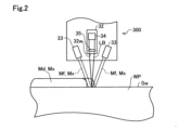
- FIG. 2 is a diagram showing in detail the configuration of part of the additional manufacturing unit 300.
- the additional manufacturing unit 300 has a function of performing additional manufacturing on the surface Sw of the workpiece WP (see the central part of FIG. 1).
- the additional manufacturing section 300 can move in the Z-axis direction with respect to the holding section 100 .
- the movement of the additional manufacturing department 300 is indicated by an arrow Az3 (see the interrupted left part of FIG. 1).
- the additional manufacturing section 300 includes a beam irradiation section 32 and a material supply section 33 .
- the beam irradiation unit 32 irradiates the light beam LB to the outside of the additional manufacturing unit 300 .
- the beam irradiation section 32 includes an oscillation section 34 and an optical system 35 .
- the oscillator 34 emits a light beam.
- the optical system 35 converges the light beam emitted by the oscillation section 34 to a focal point at a predetermined position with respect to the beam irradiation section 32 .
- FIG. 2 shows the optical system 35 in the form of a single convex lens.
- the beam irradiation unit 32 with the optical system 35 is an optical device used for depositing material on the surface Sw of the workpiece WP.
- the material supply unit 33 supplies cemented carbide powder Mf to the outside of the additional manufacturing unit 300 .
- the direction in which the light beam LB is emitted from the beam irradiation unit 32 and the direction in which the cemented carbide powder Mf is emitted from the material supply unit 33 intersect at the focal point of the light beam LB.
- the cemented carbide powder Mf supplied by the material supply unit 33 is melted by the light beam LB.
- the additional manufacturing unit 300 supplies the cemented carbide powder Mf as the material to the surface Sw of the workpiece WP held by the holding unit 100, and melts the material to form the workpiece WP.
- a material can be attached to the surface Sw. That is, the additive manufacturing unit 300 performs directed energy deposition (DED). More specifically, the additive manufacturing unit 300 performs laser metal deposition (LMD).
- DED directed energy deposition
- LMD laser metal deposition
- the powdered material is called "powder Mf".
- a structure formed by melting the powder Mf and adhering to the surface Sw of the workpiece WP is called an “additional portion Md” or an “additional layer Md”.
- the materials forming the powder Mf and the additional layer Md are collectively referred to as "material Mx”.
- the material Mx is attached to the surface Sw of the workpiece WP by the additional manufacturing unit 300, so that the workpiece WP is formed on the surface Sw of the cylindrical workpiece WP.
- An annular additional portion Md is formed around the central axis.
- the additional manufacturing unit 300 can move in the Z-axis direction with respect to the holding unit 100 (see Az3 in the middle left part of FIG. 1).
- the holding part 100 can move in the X-axis direction while rotating the workpiece WP (see Ax1 in the lower right part of FIG. 1). Therefore, by the additional manufacturing unit 300 and the holding unit 100 controlled by the control unit 900, the cemented carbide is attached to the surface Sw of the workpiece WP held and rotated by the holding unit 100, whereby the workpiece WP An additional layer Md is formed on the surface Sw of .
- the surface of the additional layer Md is not flat, but has peaks and valleys substantially parallel to the circumferential direction of the cylindrical workpiece WP.
- the additional layer Md of the material on the surface Sw of the workpiece WP can be added to the surface Sw of the workpiece WP in the combined grinder 1 without removing and reattaching the workpiece WP to the combined grinder 1. and grinding of the additional layer Md. Therefore, deviation of the position of the center of rotation in mounting the workpiece WP a plurality of times does not affect the accuracy of the shape and dimensions of the additional layer Md of material formed on the surface Sw of the workpiece WP. Therefore, the addition of the material to be formed on the surface Sw of the workpiece WP is less than the case where the formation of the additional layer Md of material on the surface Sw of the workpiece WP and the grinding of the additional layer Md are performed by different apparatuses. In the layer Md, the portion exceeding the thickness required for the product, that is, the so-called machining margin can be reduced.
- the detection unit 38 is an infrared camera (see the central part of FIG. 1).
- the detection unit 38 is fixed to the additional manufacturing unit 300 .
- the detector 38 can acquire the state of the workpiece WP.
- the detector 38 can detect coolant CL adhering to the surface Sw of the workpiece WP.
- the detection unit 38 can acquire the state of the workpiece WP irradiated with the light beam LB.
- the detector 38 is an optical instrument used for deposition of material onto the surface Sw of the workpiece WP.
- the bed 800 supports the holding section 100, the grinding section 200, the additional manufacturing section 300, the coolant supply section 400, the protection section 500, and the detection section .
- the holding unit 100 can move in the X-axis direction on the bed 800 (see Ax1 in the lower right part of FIG. 1).
- the additional manufacturing unit 300 and the detection unit 38 fixed to the additional manufacturing unit 300 can move integrally in the Z-axis direction on the bed 800 (see Az3 in FIG. 1).
- the grinding unit 200 and the coolant supply unit 400 fixed to the grinding unit 200 can move integrally in the Z-axis direction (see Az2 in the lower right part of FIG. 1).
- the control unit 900 controls the holding unit 100, the grinding unit 200, the additional manufacturing unit 300, the coolant supply unit 400, the protection unit 500, and the detection unit .
- the control unit 900 is a computer having a display 970 functioning as an output device and a keyboard 980 functioning as an input device (see FIG. 1).
- the control unit 900 further includes a CPU 940 as a processor, a RAM 950 and a ROM 960 .
- the CPU 940 loads the computer program stored in the ROM 960 into the RAM 950 and executes it to operate the holding unit 100, the grinding unit 200, the additional manufacturing unit 300, the coolant supply unit 400, the protection unit 500, and the detection unit. 38 realizes various functions to be described later.
- FIG. 3 is an explanatory diagram showing the configuration and operation of the protection section 500 and the additional manufacturing section 300.
- FIG. 3 to 5 correspond to plan views. It should be noted that FIGS. 3 to 5 do not accurately represent the dimensions and shapes of the configuration of each part. Also, in order to facilitate understanding of the technology, illustration of a part of the configuration of the composite grinder 1 is omitted in FIGS.
- the protection unit 500 prevents the coolant CL from adhering to the beam irradiation unit 32 and the detection unit 38 (see the upper central part of FIG. 3).
- the protection section 500 has a cover 51 and a pressure section 57 .
- the cover 51 covers the beam irradiation section 32 and the detection section 38 .
- the cover 51 has an opening 53 and a lid portion 52 .
- the lid portion 52 can open and close the opening 53 .
- the protective part 500 can selectively arrange the cover part 52 at the open position Po and the closed position Pc.
- FIG. 4 is an explanatory view showing the state of the protection section 500 and the additional manufacturing section 300 when the workpiece WP held by the holding section 100 is being ground by the grinding wheel 21 of the grinding section 200.
- FIG. When the workpiece WP held by the holding section 100 is ground by the grinding wheel 21 of the grinding section 200, the grinding section 200 moves to a position closer to the rotation axis of the headstock 13 than in the state shown in FIG. See Az2 in FIG. 4).
- the lid part 52 When the workpiece WP held by the holding part 100 is ground by the grinding wheel 21 of the grinding part 200, the lid part 52 is arranged at the closed position Pc (see the central part of FIG. 4). In this state, the additive manufacturing section 300 is inside the cover 51 . That is, the beam irradiation section 32 and the detection section 38 are covered with the cover 51 . Therefore, the beam irradiation unit 32 cannot irradiate the light beam LB onto the surface Sw of the workpiece WP. The detector 38 cannot acquire the state of the workpiece WP.
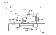
- FIG. 5 is an explanatory diagram showing the state of the protective section 500 and the additional manufacturing section 300 when the additional manufacturing section 300 attaches the material Mx to the surface Sw of the workpiece WP.
- the grinding unit 200 moves to a position farther from the rotation axis of the headstock 13 than in the state shown in FIG. 4 (see Az2 in FIG. 5).
- the lid section 52 When the additional manufacturing section 300 attaches the material Mx to the surface Sw of the workpiece WP, the lid section 52 is arranged at the open position Po (see the central part of FIG. 5). When the lid portion 52 is at the open position Po, the opening 53 of the cover 51 is opened. At this time, the lid portion 52 has moved upward, that is, in the positive direction of the Y-axis from the position of closing the opening of the cover 51 shown in FIG. Note that FIG. 5 does not show the lid portion 52 retracted upward. Through the opening of the cover 51, the additional manufacturing section 300 has moved along the Z-axis direction to a position closer to the rotation axis of the headstock 13 than in the state shown in FIG. 4 (see Az3 in the middle left part of FIG. 5). . That is, the beam irradiation section 32 and the detection section 38 are not covered with the cover 51 .
- the beam irradiation unit 32 emits the light beam LB through the opening 53 onto the surface Sw of the workpiece WP.
- the material supply unit 33 supplies cemented carbide powder Mf to the surface Sw of the workpiece WP through the opening 53 .
- the detector 38 takes in the light reflected by the workpiece WP through the aperture 53 .
- the material supply unit 33 is not shown in FIGS. 3 to 5. FIG.
- the coolant CL scattered by the rotating grinding wheel 21 and the rotating workpiece WP is scattered by the beam irradiation unit 32.
- the detection unit 38 and the possibility that the accuracy of the attachment of the material Mx to the surface Sw by the additional manufacturing unit 300 is lowered can be reduced.
- the possibility that the coolant CL adheres to the beam irradiation unit 32 and the detection unit 38 and causes the beam irradiation unit 32 and the detection unit 38 to malfunction can be reduced.
- the droplets 52 is closed and adheres to the cover 51 covering the beam irradiation section 32 and the detection section 38 . Therefore, the possibility that the coolant CL adheres to the beam irradiation section 32 and the detection section 38 can be reduced.
- the pressure unit 57 can increase the pressure in the space inside the cover 51 that houses the beam irradiation unit 32 and the detection unit 38 .
- the pressurizing unit 57 is specifically a compressor.
- the pressure unit 57 compresses external air and supplies it into the cover 51 , thereby maintaining the pressure in the space inside the cover 51 where the opening 53 is closed higher than the pressure around the cover 51 .
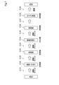
- FIG. 6 is a flow diagram showing processing for machining the workpiece WP.
- a cylindrical workpiece WP before processing is prepared as a material to be processed (see the right part of FIG. 6).
- workpiece WP the object before the processing of FIG. 6 and the object after the processing of FIG. 6 are both referred to as workpiece WP.
- step S10 the workpiece WP is transported to a cutting machine different from the composite grinder 1 and attached to the chuck of the cutting machine.
- step S20 a cutting machine is used to perform turning and drilling on the workpiece WP.
- step S30 the workpiece WP is removed from the cutting machine. Then, the workpiece WP is transported to the compound grinder 1 of the first embodiment and attached to the headstock 13 of the compound grinder 1 (see the lower part of FIG. 1).
- step S40 the combined grinder 1 is used to perform additive manufacturing and grinding, which is removal processing, on the workpiece WP.
- Step S40 includes steps S42, S44, S46, and S48. While steps S42, S44, S46, and S48 are performed, the workpiece WP is not removed from the headstock 13 and the tailstock 14, but continues to be held by the headstock 13 and the tailstock 14. FIG.
- step S42 rough grinding is performed on the workpiece WP. More specifically, rough grinding is performed by the grinding unit 200 rotating the grinding wheel 21 and bringing it into contact with the workpiece WP rotated by the holding unit 100 .
- the coolant supply part 400 supplies the coolant CL to the part CP where the workpiece WP held by the holding part 100 and the grinding wheel 21 are in contact with each other.
- a grinding wheel 21 for rough grinding in step S42 is attached to the grinding section 200 .
- the lid portion 52 of the protective portion 500 is arranged at the closed position Pc (see the central portion of FIG. 4).
- the beam irradiation section 32 and the detection section 38 are covered with the cover 51 of the protective section 500 .
- a functional unit of the CPU 940 that controls each unit to perform rough grinding in step S42 is shown as a first rough grinding unit 942 in FIG.
- the grinding section 200 moves to a position farther from the rotation axis of the headstock 13 than in the state shown in FIG. 4 (see Az2 in FIG. 5).
- the lid portion 52 of the protective portion 500 is arranged at the open position Po (see the central portion of FIG. 5).
- the additional manufacturing unit 300 moves through the opening of the cover 51 to a position closer to the rotation axis of the headstock 13 than in the state shown in FIG. 4 (see Az3 in FIG. 5).
- step S42 the grinding wheel for rough grinding in step S42 attached to the grinding section 200 is replaced with the grinding wheel for rough grinding in step S46.
- step S44 hard material build-up processing is performed. More specifically, the additional manufacturing section 300 forms an additional layer Md of cemented carbide on the surface Sw of the workpiece WP (see FIG. 2).
- the controller 900 first detects the coolant CL adhered to the surface Sw of the workpiece WP by the detector 38 . Then, based on the detection result of the detection unit 38, the control unit 900 controls the output of the light beam LB when the material Mx is attached to the surface Sw.
- the additional manufacturing section 300 moves into the cover 51 under the control of the control section 900 (see Az3 in FIG. 4).
- the lid portion 52 of the protective portion 500 is arranged at the closed position Pc (see the central portion of FIG. 4).
- the opening 53 of the cover 51 is closed by the lid portion 52 when the lid portion 52 is at the closed position Pc.
- the grinding unit 200 moves to a position closer to the rotation axis of the headstock 13 than in the state shown in FIG. 5 (see Az2 in FIG. 4).
- step S46 rough grinding is performed on the workpiece WP. More specifically, the grinding unit 200 brings the grinding wheel 21 into contact with the workpiece WP, which is being rotated by the holding unit 100, while rotating the grinding wheel 21, thereby grinding the additional layer Md formed on the workpiece WP. and perform rough grinding.
- the coolant supply part 400 supplies the coolant CL to the part CP where the workpiece WP held by the holding part 100 and the grinding wheel 21 are in contact with each other. As a result, the ridges formed on the surface of the additional layer Md are roughly removed.
- a grinding wheel 21 for rough grinding in step S46 is attached to the grinding section 200 .
- the lid portion 52 of the protective portion 500 is arranged at the closed position Pc (see the central portion of FIG. 4).
- the beam irradiation unit 32 and the detection unit 38 are covered with the cover 51 of the protective unit 500 (see FIG. 4).
- a functional unit of the CPU 940 that controls each unit to perform rough grinding in step S46 is shown as a second rough grinding unit 946 in FIG.
- the grinding section 200 moves to a position farther from the rotation axis of the headstock 13 than in the state shown in FIG. 4 (see Az2 in FIG. 5).
- the grinding wheel for rough grinding in step S46 attached to the grinding section 200 is replaced with the grinding wheel for finish grinding in step S48. After that, the grinding section 200 moves to a position closer to the rotation axis of the headstock 13 than in the state shown in FIG. 5 (see Az2 in FIG. 4).
- step S48 finish grinding is performed on the workpiece WP. More specifically, the grinding unit 200 brings the grinding wheel 21 into contact with the workpiece WP, which is being rotated by the holding unit 100, while rotating the grinding wheel 21, thereby grinding the additional layer Md formed on the workpiece WP. and perform finish grinding.
- the coolant supply part 400 supplies the coolant CL to the part CP where the workpiece WP held by the holding part 100 and the grinding wheel 21 are in contact with each other. As a result, the surface of the additional layer Md is processed flat.
- a grinding wheel 21 for finish grinding in step S48 is attached to the grinding section 200 .
- the lid portion 52 of the protective portion 500 is arranged at the closed position Pc (see the central portion of FIG. 4).
- the beam irradiation unit 32 and the detection unit 38 are covered with the cover 51 of the protective unit 500 (see FIG. 4).
- a functional unit of the CPU 940 that controls each unit to perform finish grinding in step S48 is shown as a finish grinding unit 948 in FIG.
- the grinding section 200 moves to a position farther from the rotation axis of the headstock 13 than in the state shown in FIG. 4 (see Az2 in FIG. 5).
- step S50 the workpiece WP is removed from the headstock 13 of the compound grinder 1 (see the lower part of FIG. 1) and transported to a predetermined finished product storage site. With the above processing, the processing for machining the workpiece WP is completed.
- FIG. 7 is a flowchart showing conventional processing for machining the workpiece WP.
- the processing from preparation of the material to be processed to step S120 is the same as the processing from preparation of the material to be processed in FIG. 6 of the present embodiment to S20. be.
- the workpiece WP is removed from the cutting machine.
- the workpiece WP is then transported to a conventional grinder and mounted on the grinder's headstock.
- step S142 rough grinding is performed on the workpiece WP in the grinding machine. At this time, the grinding wheel 21 for rough grinding in step S142 is attached to the grinder.
- step S142 After rough grinding, the grinding wheel for rough grinding in step S142 attached to the grinder is replaced with the grinding wheel for rough grinding in step S146.
- step S143 the workpiece WP is removed from the grinder. Then, the workpiece WP is transported to the DED machine, and the workpiece WP is attached to the DED machine.
- step S144 hard material build-up processing is performed. More specifically, the DED machine forms an additional layer Md of cemented carbide on the surface Sw of the workpiece WP (see FIG. 2).
- step S145 the workpiece WP is removed from the DED processing machine.
- the workpiece WP is then transported to a conventional grinding machine and mounted on the spindle of the grinding machine (see bottom of FIG. 1).
- step S146 rough grinding is performed on the workpiece WP.
- a grinding wheel 21 for rough grinding in step S146 is attached to the grinder.
- step S147 the grinding wheel for rough grinding in step S146 attached to the grinder is replaced with the grinding wheel for finish grinding in step S148.
- step S148 finish grinding is performed on the workpiece WP.
- a grinding wheel 21 for finish grinding in step S48 is attached to the grinding section 200 .
- step S150 the workpiece WP is removed from the headstock of the grinder and transported to a predetermined finished product storage site.
- the above processing completes the conventional processing for machining the workpiece WP.
- steps S42, S44, S46, and S48 of the present embodiment the combined grinder 1 is used to perform additional manufacturing and grinding, which is removal processing, on the workpiece WP. (See S40 in FIG. 6). Therefore, the workpiece WP is not removed from and attached to the composite grinder 1 during this time. Therefore, a so-called machining margin can be set small. Moreover, in the composite grinder 1, there is no need for transportation of the workpiece WP between processing devices and setup work in each processing device. Therefore, compared to the process of FIG. 7, the time required for machining the workpiece WP can be shortened. As a result, the machining cost of the workpiece WP can also be reduced.
- one combined grinder 1 performs additive manufacturing and grinding, which is removal processing (see S40 in FIG. 6). Therefore, the space required for these processes in the factory can be reduced compared to the embodiment of FIG. 7 which uses a grinding machine and a DED machine.
- Hexavalent chromium is used in embodiments in which the workpiece WP is plated instead of DED.
- the additional layer Md is formed on the surface Sw of the workpiece WP by DED instead of by plating. Therefore, treatment and management of hexavalent chromium are unnecessary.
- the grinding wheel 21 in this embodiment is also called “grinding stone”.
- the beam irradiation unit 32 is also called an "optical device”.
- Second embodiment In the composite grinder 2 of the second embodiment, the arrangement of the grinding section 202 and the additional manufacturing section 302, and the configuration of the protection section 502 are similar to the grinding section 200 and the additional manufacturing section of the composite grinder 1 of the first embodiment, respectively. 300 and the configuration of the protection part 500 are different. Further, in the second embodiment, the configuration of a part of the surfaces of the beam irradiation section 32 and the material supply section 33 is different from that of the beam irradiation section 32 and the material supply section 33 of the first embodiment. Other points of the composite grinder 2 of the second embodiment are the same as those of the composite grinder 1 of the first embodiment.
- FIG. 8 is an explanatory diagram showing the arrangement of the grinding section 202, the additional manufacturing section 302, and the protective section 502. As shown in FIG. FIG. 8 corresponds to FIG. 8 to 10 correspond to plan views. 8 to 10 do not accurately represent the dimensions and shapes of the configuration of each part. Also, in order to facilitate understanding of the technology, illustration of a part of the configuration of the composite grinder 2 is omitted in FIGS.
- the grinding section 202 has a configuration corresponding to each configuration of the grinding section 200 of the composite grinding machine 1 of the first embodiment, and has the same function as the grinding section 200 .
- components having the same functions as the components shown in FIG. 3 are denoted by the same reference numerals.
- a liquid supply section (not shown) has the same configuration as the coolant supply section 400 of the composite grinder 1 of the first embodiment.
- the liquid supply section is fixed relative to the grinding section 202 .
- the additional manufacturing section 302 has a configuration corresponding to each configuration of the additional manufacturing section 300 of the composite grinder 1 of the first embodiment, and has the same function as the additional manufacturing section 300 .
- the beam irradiation unit 32 faces the Z-axis negative direction.
- the grinding section 202 and the additional manufacturing section 302 are integrated.
- the outer surfaces of the beam irradiation section 32 and the detection section 38 are provided with a structure that repels the coolant CL.
- the outer surface of the window portion 32w through which the light beam LB passes in the beam irradiation portion 32 is coated with polytetrafluoroethylene (PTFE) (see FIG. 2).
- PTFE polytetrafluoroethylene
- the detection section 38 the outer surface of the window through which the external light taken into the detection section 38 passes is coated with PTFE.
- the protection section 502 supports the grinding section 202, the additional manufacturing section 302, and the liquid supply section.
- the protection unit 502 includes a rotary shaft that supports the grinding unit 202, the additional manufacturing unit 302, and the liquid supply unit, and a motor that rotates the rotary shaft.
- the protection unit 502 can arrange the grinding unit 202, the additional manufacturing unit 302, and the liquid supply unit in two directions 180 degrees different from each other about an axis parallel to the Y-axis direction.
- the rotation of the grinding section 202, the additional manufacturing section 302, and the liquid supply section is indicated by an arrow Ar in FIG.
- the center of rotation is indicated by RA.
- the protection section 502 can move the grinding section 202, the additional manufacturing section 302, and the liquid supply section along the Z-axis direction to a position closer to the rotation axis of the headstock 13 than in the state shown in FIG. In FIGS. 8 to 10, the movement of the grinding section 202 and the additional manufacturing section 302 in the Z-axis direction is indicated by an arrow Az.
- FIG. 9 is an explanatory diagram showing the state of the protection section 502 and the additional manufacturing section 302 when the workpiece WP held by the holding section 100 is being ground by the grinding wheel 21 of the grinding section 202.
- FIG. FIG. 9 corresponds to FIG.
- the grinding section 202 moves to a position closer to the rotation axis of the headstock 13 than in the state shown in FIG. (See Az in FIG. 9).
- the grinding wheel 21 When the workpiece WP held by the holding section 100 is ground by the grinding wheel 21 of the grinding section 202, the grinding wheel 21 is placed at the opposite position CP where the workpiece WP and the grinding wheel 21 are in contact with each other.
- a beam irradiation unit 32 and a detection unit 38 are arranged on the side (see the upper right part of FIG. 9).
- FIG. 10 is an explanatory diagram showing the state of the protection section 502 and the additional manufacturing section 302 when the additional manufacturing section 302 attaches the material Mx to the surface Sw of the workpiece WP.
- FIG. 10 corresponds to FIG.
- the arrangement of FIG. 10 of the additional manufacturing section 302 including the beam irradiation section 32, the grinding section 202, and the liquid supply section is called "first equipment arrangement L1".
- the arrangement in FIG. 9 of the additional manufacturing section 302 including the beam irradiation section 32, the grinding section 202, and the liquid supply section is called "second equipment arrangement L2".
- the protection unit 502 arranges the grinding unit 202, the additional manufacturing unit 302, and the liquid supply unit in an orientation that is 180° different from the orientation in FIG. .
- the beam irradiation unit 32 faces the positive direction of the Z-axis.
- the beam irradiation unit 32 can irradiate the surface Sw of the workpiece WP with the light beam LB.
- the detector 38 can acquire the state of the workpiece WP.
- the additional manufacturing unit 302 can adhere the material Mx to the surface Sw of the workpiece WP (see FIG. 2).
- the grinding wheel 21 of the grinding section 202 is positioned farther from the rotation axis of the headstock 13 than in the state of FIG. 9 (see the middle right portion of FIG. 10).
- the coolant CL can be supplied without disposing a structure such as the lid portion 52 between the portion CP where the workpiece WP and the grinding wheel 21 are in contact with each other and the beam irradiation portion 32. It is possible to reduce the possibility of adhesion to the beam irradiation section 32 (see FIGS. 4 and 9). Therefore, it is possible to reduce the number of components arranged on the bed 800 as compared with a mode having a configuration such as the cover 51 and the lid portion 52 . As a result, a large space can be secured on the bed 800 in which the grinding wheel 21 and the beam irradiation unit 32 can be moved. Therefore, it is possible to increase the degree of freedom in arranging components such as the grinding wheel 21 during grinding and the degree of freedom in arranging components such as the beam irradiation unit 32 during additive manufacturing (Az, Ax1).
- the arrangement of the grinding section 203 and the additional manufacturing section 303 and the configuration of the protective section 503 are the same as those of the composite grinder 1 of the first embodiment. 300 and differs from guard 500 .
- the process of evaporating the coolant is performed prior to the hard material build-up process.
- Other points of the composite grinder 3 of the third embodiment are the same as those of the composite grinder 1 of the first embodiment.
- FIG. 11 is an explanatory diagram showing the arrangement of the grinding section 203, the additional manufacturing section 303, and the protection section 503. As shown in FIG. FIG. 11 corresponds to FIG. 11 to 13 correspond to plan views. It should be noted that FIGS. 11 to 13 do not accurately represent the dimensions and shapes of the configuration of each part. 11 to 13, illustration of a part of the configuration of the composite grinder 3 is omitted in order to facilitate understanding of the technology.
- the grinding section 203 has a configuration corresponding to each configuration of the grinding section 200 of the composite grinder 1 of the first embodiment, and has the same function as the grinding section 200 .
- components having the same functions as the components shown in FIG. 3 are denoted by the same reference numerals.
- a liquid supply section (not shown) has the same configuration as the coolant supply section 400 of the composite grinder 1 of the first embodiment.
- the liquid supply section is fixed with respect to the grinding section 203 .
- the additional manufacturing section 303 has a configuration corresponding to each configuration of the additional manufacturing section 300 of the composite grinder 1 of the first embodiment, and has the same function as the additional manufacturing section 300 .
- the additional manufacturing unit 303 is arranged on the opposite side of the part CP where the workpiece WP and the grinding wheel 21 are in contact with the workpiece WP held by the holding unit 100. .
- the protective part 503 is an air curtain.
- the protective portion 503 can generate an air flow Ab between the beam irradiation portion 32 and the portion CP where the workpiece WP held by the holding portion 100 and the grinding wheel 21 are in contact with each other. More specifically, the protective portion 503 causes an air flow Ab between the side of the workpiece WP held by the holding portion 100 opposite to the portion CP and the beam irradiation portion 32 .
- the air flow Ab generated by the protective portion 503 has a direction from the protective portion 503 toward the positive direction of the X axis.
- the airflow Ab generated by the protection unit 503 is emitted to a range including the range occupied by the beam irradiation unit 32 in the Y-axis direction.
- FIG. 12 is an explanatory view showing the state of the protective section 503 and the additional manufacturing section 303 when the workpiece WP held by the holding section 100 is being ground by the grinding wheel 21 of the grinding section 203.
- FIG. FIG. 12 corresponds to FIG.
- the grinding section 203 moves closer to the rotation axis of the headstock 13 than in the state shown in FIG. (See Az2 in FIG. 12).
- the protective section 503 protects the portion CP where the workpiece WP and the grinding wheel 21 contact and the beam irradiation section 32 Air flow Ab is generated between .
- FIG. 13 is an explanatory diagram showing the state of the protection section 503 and the additional manufacturing section 303 when the additional manufacturing section 303 attaches the material Mx to the surface Sw of the workpiece WP.
- FIG. 13 corresponds to FIG.
- the additional manufacturing unit 303 attaches the material Mx to the surface Sw of the workpiece WP
- the additional manufacturing unit 303 moves to a position closer to the rotation axis of the headstock 13 than the state shown in FIG. 12 (see Az3 in FIG. 13).
- the additional manufacturing section 303 can adhere the material Mx to the surface Sw of the workpiece WP (see FIG. 2).
- the grinding section 203 has moved to a position farther from the rotation axis of the headstock 13 than in the state shown in FIG. 12 (see Az2 in FIG. 13).
- step S44 of FIG. 6 the process of evaporating the coolant is performed prior to the hard material build-up process.
- the control unit 900 causes the holding unit 100 to rotate and move the workpiece WP in the X-axis direction, while the detection unit 38 detects the coolant CL adhering to the surface Sw of the workpiece WP. do.
- the control unit 900 controls the beam irradiation unit 32 to irradiate the coolant CL adhering to the workpiece WP with the light beam LB, thereby evaporating the coolant CL.
- the process of controlling each part in step S44 to evaporate the coolant CL is indicated by a dashed line in FIG.
- a functional unit of the CPU 940 that realizes the process of evaporating the coolant CL by controlling each unit in step S44 is shown as an evaporating unit 944b in FIG.
- the coolant CL adhered to the workpiece WP is evaporated and removed prior to the attachment of the material Mx to the surface Sw of the workpiece WP by the additional manufacturing unit 303 (see S44 in FIG. 6). be able to. Therefore, it is possible to reduce the possibility that the accuracy of adhesion of the material Mx to the surface Sw of the workpiece WP by the additional manufacturing unit 303 is lowered due to the coolant CL adhered to the workpiece WP.
- D. Other embodiments D1.
- Alternative Embodiment 1 (1)
- the material supply unit 33 supplies the cemented carbide powder Mf to the outside of the additional manufacturing unit 300 .
- various materials such as Fe-based alloys, Ni-based alloys, Co-based alloys, Cu-based alloys, Al-based alloys, and ceramics can be used as materials for the additional layer Md.
- These alloys can be alloys with additions of chromium, cobalt, vanadium and the like.
- various materials such as carbon steel, bearing steel, stainless steel, and aluminum can be used as the material of the workpiece.
- the material supply unit 33 supplies the cemented carbide powder Mf to the outside of the additional manufacturing unit 300 .
- the material supply can also supply material in the form of wires.
- the material supplied by the material supply unit can be high-speed steel in addition to cemented carbide.
- the grinding section 200 and the additional manufacturing section 300 move in the Z-axis direction, and the holding section 100 moves in the X-axis direction.
- one of the grinding portion and the holding portion may be configured to be movable in two directions perpendicular to each other.
- the composite grinder should be configured so that the grinding portion can take any position in the plane relative to the holding portion.
- one of the additional manufacturing section and the holding section may be configured to be movable in two directions perpendicular to each other.
- the composite grinder may be configured so that the additional manufacturing section can take any position in the plane relative to the holding section.
- the cover 51 covers the beam irradiation section 32 and the detection section 38 as a whole.
- the cover has, for example, a portion opposite to the portion of the beam irradiation portion 32 where the window portion 32w through which the light beam LB passes, or a window portion through which external light taken into the detection portion 38 passes. It is also possible to adopt a mode in which a part of the optical device, such as a part on the opposite side of the part where the optical device is covered, is not covered.
- the lid section 52 when the workpiece WP held by the holding section 100 is ground by the grinding wheel 21 of the grinding section 200, the lid section 52 is arranged at the closed position Pc ( See the central part of FIG. 4). However, the lid portion 52 can also be placed in the closed position Pc while other processing that is not impossible to manufacture is being performed, such as, for example, while the coolant is being evaporated (see FIG. 6). S44 reference).
- the detection unit 38 is an infrared camera.
- the detection unit may have other configurations such as a digital still camera that records visible light or a camera that can record moving images.
- the detection unit may be any device as long as it can detect the coolant adhering to the surface of the workpiece.
- the protection unit 502 arranges the grinding unit 202, the additional manufacturing unit 302, and the liquid supply unit in two directions different from each other by 180° about the axis parallel to the Y-axis direction. It is possible. However, the two equipment arrangements that the grinding section and the additional manufacturing section can take may be arrangements having two different orientations, such as 90° and 120°, which are less than 180° from each other. Additionally, the two instrument configurations can be achieved by any combination of instrument rotation, linear movement, and curvilinear movement.
- coolant repellent structures are not limited to the addition of chemicals such as PTFE to the surfaces of components.
- the structure that repels coolant may be realized as a so-called functional surface by providing a texture to the surface properties of the component so that the coolant is less likely to adhere.
- the performance such as water repellency and oil repellency of the surface of the component can be determined according to the coolant used in the composite grinder.
- the beam irradiation section 32 of the additional manufacturing section 300 irradiates a laser beam.
- the additional manufacturing department may heat and melt the material by irradiating arc plasma or electron beam instead of laser beam.
- the compound grinder 1 includes the beam irradiation section 32 as an optical device and the protective section 500 .
- the compound grinder may be configured without such optics and/or guards.
- the cover 51 has the opening 53 and the lid portion 52 .
- the cover that covers the optical equipment has a window that allows light to pass from the inside of the cover to the outside and from the outside to the inside, and a removal part that can remove the coolant adhering to the window.
- the removal unit may be configured to remove the coolant adhering to the window by spraying a fluid onto the window, for example.
- the removal section can be configured to have a function of wiping off the coolant adhering to the window section.
- the protective part 500 has the pressurizing part 57 (see the upper central part of FIG. 3). However, the protective part 500 may have the cover 51 and may not have the pressurizing part 57 .
- the protective portion 503 is an air curtain.
- the protective part can also be a shield as a specific structure that is arranged between the optical device and the workpiece and blocks movement of the coolant. Such shields are preferably retracted from between the optics and the workpiece when the additive manufacturing station deposits material on the surface of the workpiece.
- step S44 of FIG. 6 the process of evaporating the coolant is performed prior to the hard material build-up process. A portion of the coolant may remain on the surface of the workpiece after the process of evaporating the coolant. Moreover, it is also possible to adopt a mode in which the process of evaporating the coolant is not performed prior to the hard material build-up process.
- the control unit 900 In the hard material build-up process of the first embodiment, the control unit 900 first uses the detection unit 38 to detect the coolant CL adhering to the surface Sw of the workpiece WP. Then, based on the detection result of the detection unit 38, the control unit 900 controls the output of the light beam LB when the material Mx is attached to the surface Sw. However, without such processing, for example, the output of the light beam LB may be controlled to be constant.
- the present disclosure is not limited to the above-described embodiments, and can be implemented in various configurations without departing from the scope of the present disclosure.
- the technical features of the embodiments corresponding to the technical features in each form described in the outline of the invention are used to solve some or all of the above problems, or Alternatively, replacements and combinations can be made as appropriate to achieve all. Also, if the technical features are not described as essential in this specification, they can be deleted as appropriate.
Landscapes
- Engineering & Computer Science (AREA)
- Mechanical Engineering (AREA)
- Physics & Mathematics (AREA)
- Optics & Photonics (AREA)
- Plasma & Fusion (AREA)
- Grinding Of Cylindrical And Plane Surfaces (AREA)
Priority Applications (5)
| Application Number | Priority Date | Filing Date | Title |
|---|---|---|---|
| US18/685,376 US20260054335A1 (en) | 2021-09-06 | 2021-09-06 | Composite grinding machine |
| DE112021008197.7T DE112021008197T5 (de) | 2021-09-06 | 2021-09-06 | Verbundschleifmaschine |
| PCT/JP2021/032635 WO2023032196A1 (ja) | 2021-09-06 | 2021-09-06 | 複合研削盤 |
| CN202180101605.8A CN117881501A (zh) | 2021-09-06 | 2021-09-06 | 复合磨床 |
| JP2023544972A JPWO2023032196A1 (https=) | 2021-09-06 | 2021-09-06 |
Applications Claiming Priority (1)
| Application Number | Priority Date | Filing Date | Title |
|---|---|---|---|
| PCT/JP2021/032635 WO2023032196A1 (ja) | 2021-09-06 | 2021-09-06 | 複合研削盤 |
Publications (1)
| Publication Number | Publication Date |
|---|---|
| WO2023032196A1 true WO2023032196A1 (ja) | 2023-03-09 |
Family
ID=85411789
Family Applications (1)
| Application Number | Title | Priority Date | Filing Date |
|---|---|---|---|
| PCT/JP2021/032635 Ceased WO2023032196A1 (ja) | 2021-09-06 | 2021-09-06 | 複合研削盤 |
Country Status (5)
| Country | Link |
|---|---|
| US (1) | US20260054335A1 (https=) |
| JP (1) | JPWO2023032196A1 (https=) |
| CN (1) | CN117881501A (https=) |
| DE (1) | DE112021008197T5 (https=) |
| WO (1) | WO2023032196A1 (https=) |
Citations (4)
| Publication number | Priority date | Publication date | Assignee | Title |
|---|---|---|---|---|
| US4980534A (en) * | 1988-11-18 | 1990-12-25 | Toyoda Koki Kabushiki Kaisha | Method and device for treating machined surface of workpiece |
| WO2015091837A1 (en) * | 2013-12-18 | 2015-06-25 | Aktiebolaget Skf | A machine for grinding a work-piece customized by additive manufacturing |
| JP2017018979A (ja) * | 2015-07-09 | 2017-01-26 | Dmg森精機株式会社 | 加工機械 |
| JP6810823B1 (ja) * | 2020-09-01 | 2021-01-06 | Dmg森精機株式会社 | ワークの付加加工方法および加工機械 |
Family Cites Families (3)
| Publication number | Priority date | Publication date | Assignee | Title |
|---|---|---|---|---|
| JP6345341B2 (ja) * | 2015-04-08 | 2018-06-20 | 三菱電機株式会社 | 研削加工方法及び研削装置 |
| JP5940712B1 (ja) * | 2015-05-25 | 2016-06-29 | Dmg森精機株式会社 | 加工機械 |
| JP6439668B2 (ja) | 2015-12-14 | 2018-12-19 | 住友金属鉱山株式会社 | ガス放出機構付きキャンロールの製造方法 |
-
2021
- 2021-09-06 US US18/685,376 patent/US20260054335A1/en active Pending
- 2021-09-06 JP JP2023544972A patent/JPWO2023032196A1/ja active Pending
- 2021-09-06 WO PCT/JP2021/032635 patent/WO2023032196A1/ja not_active Ceased
- 2021-09-06 CN CN202180101605.8A patent/CN117881501A/zh active Pending
- 2021-09-06 DE DE112021008197.7T patent/DE112021008197T5/de active Pending
Patent Citations (4)
| Publication number | Priority date | Publication date | Assignee | Title |
|---|---|---|---|---|
| US4980534A (en) * | 1988-11-18 | 1990-12-25 | Toyoda Koki Kabushiki Kaisha | Method and device for treating machined surface of workpiece |
| WO2015091837A1 (en) * | 2013-12-18 | 2015-06-25 | Aktiebolaget Skf | A machine for grinding a work-piece customized by additive manufacturing |
| JP2017018979A (ja) * | 2015-07-09 | 2017-01-26 | Dmg森精機株式会社 | 加工機械 |
| JP6810823B1 (ja) * | 2020-09-01 | 2021-01-06 | Dmg森精機株式会社 | ワークの付加加工方法および加工機械 |
Also Published As
| Publication number | Publication date |
|---|---|
| JPWO2023032196A1 (https=) | 2023-03-09 |
| US20260054335A1 (en) | 2026-02-26 |
| DE112021008197T5 (de) | 2024-07-25 |
| CN117881501A (zh) | 2024-04-12 |
Similar Documents
| Publication | Publication Date | Title |
|---|---|---|
| TWI821273B (zh) | 基板處理系統及基板處理方法 | |
| JP2024041884A (ja) | 基板処理方法 | |
| CN1087353C (zh) | 激光引发的表面改进 | |
| KR20170119624A (ko) | SiC 웨이퍼의 가공 방법 | |
| JP6685817B2 (ja) | SiCウエーハの加工方法 | |
| JP6692578B2 (ja) | ウェーハの加工方法 | |
| WO2023032196A1 (ja) | 複合研削盤 | |
| JP2009130173A (ja) | ダイシング装置 | |
| CN115768587B (zh) | 激光焊接方法以及激光焊接装置 | |
| JP7736072B2 (ja) | 複合研削盤 | |
| JP7694672B2 (ja) | 複合加工機 | |
| JP2024068073A (ja) | 複合研削盤 | |
| JP7482227B2 (ja) | ワークの加工方法および加工機械 | |
| JP7772518B2 (ja) | ウエーハの処理方法 | |
| JP7072110B1 (ja) | 損傷部品の補修方法 | |
| CN116572101A (zh) | 加工系统 | |
| JP2022021124A (ja) | ウエーハの研削方法 | |
| JP7709327B2 (ja) | ウエーハの処理方法 | |
| JP7840739B2 (ja) | ウエーハの加工方法 | |
| JPH02241688A (ja) | 複合加工法 | |
| TW202342212A (zh) | 光學構件及雷射加工機 | |
| JP7731776B2 (ja) | ウエーハの処理方法 | |
| JP7648436B2 (ja) | 切削装置、及び、マウントフランジの修正方法 | |
| JP7473414B2 (ja) | ウエーハの加工方法 | |
| JPH035937B2 (https=) |
Legal Events
| Date | Code | Title | Description |
|---|---|---|---|
| 121 | Ep: the epo has been informed by wipo that ep was designated in this application |
Ref document number: 21955291 Country of ref document: EP Kind code of ref document: A1 |
|
| WWE | Wipo information: entry into national phase |
Ref document number: 202180101605.8 Country of ref document: CN |
|
| WWE | Wipo information: entry into national phase |
Ref document number: 2023544972 Country of ref document: JP |
|
| WWE | Wipo information: entry into national phase |
Ref document number: 112021008197 Country of ref document: DE |
|
| 122 | Ep: pct application non-entry in european phase |
Ref document number: 21955291 Country of ref document: EP Kind code of ref document: A1 |