WO2023032186A1 - 無給電素子 - Google Patents
無給電素子 Download PDFInfo
- Publication number
- WO2023032186A1 WO2023032186A1 PCT/JP2021/032610 JP2021032610W WO2023032186A1 WO 2023032186 A1 WO2023032186 A1 WO 2023032186A1 JP 2021032610 W JP2021032610 W JP 2021032610W WO 2023032186 A1 WO2023032186 A1 WO 2023032186A1
- Authority
- WO
- WIPO (PCT)
- Prior art keywords
- parasitic element
- loop antenna
- loop
- extension
- transmitter
- Prior art date
- Legal status (The legal status is an assumption and is not a legal conclusion. Google has not performed a legal analysis and makes no representation as to the accuracy of the status listed.)
- Ceased
Links
Images




Classifications
-
- H—ELECTRICITY
- H01—ELECTRIC ELEMENTS
- H01Q—ANTENNAS, i.e. RADIO AERIALS
- H01Q5/00—Arrangements for simultaneous operation of antennas on two or more different wavebands, e.g. dual-band or multi-band arrangements
- H01Q5/30—Arrangements for providing operation on different wavebands
- H01Q5/378—Combination of fed elements with parasitic elements
-
- H—ELECTRICITY
- H01—ELECTRIC ELEMENTS
- H01Q—ANTENNAS, i.e. RADIO AERIALS
- H01Q7/00—Loop antennas with a substantially uniform current distribution around the loop and having a directional radiation pattern in a plane perpendicular to the plane of the loop
-
- H—ELECTRICITY
- H01—ELECTRIC ELEMENTS
- H01Q—ANTENNAS, i.e. RADIO AERIALS
- H01Q1/00—Details of, or arrangements associated with, antennas
- H01Q1/12—Supports; Mounting means
- H01Q1/22—Supports; Mounting means by structural association with other equipment or articles
- H01Q1/2208—Supports; Mounting means by structural association with other equipment or articles associated with components used in interrogation type services, i.e. in systems for information exchange between an interrogator/reader and a tag/transponder, e.g. in Radio Frequency Identification [RFID] systems
- H01Q1/2241—Supports; Mounting means by structural association with other equipment or articles associated with components used in interrogation type services, i.e. in systems for information exchange between an interrogator/reader and a tag/transponder, e.g. in Radio Frequency Identification [RFID] systems used in or for vehicle tyres
-
- H—ELECTRICITY
- H01—ELECTRIC ELEMENTS
- H01Q—ANTENNAS, i.e. RADIO AERIALS
- H01Q1/00—Details of, or arrangements associated with, antennas
- H01Q1/12—Supports; Mounting means
- H01Q1/22—Supports; Mounting means by structural association with other equipment or articles
- H01Q1/24—Supports; Mounting means by structural association with other equipment or articles with receiving set
-
- H—ELECTRICITY
- H01—ELECTRIC ELEMENTS
- H01Q—ANTENNAS, i.e. RADIO AERIALS
- H01Q1/00—Details of, or arrangements associated with, antennas
- H01Q1/42—Housings not intimately mechanically associated with radiating elements, e.g. radome
-
- H—ELECTRICITY
- H01—ELECTRIC ELEMENTS
- H01Q—ANTENNAS, i.e. RADIO AERIALS
- H01Q9/00—Electrically-short antennas having dimensions not more than twice the operating wavelength and consisting of conductive active radiating elements
- H01Q9/04—Resonant antennas
- H01Q9/16—Resonant antennas with feed intermediate between the extremities of the antenna, e.g. centre-fed dipole
-
- H—ELECTRICITY
- H01—ELECTRIC ELEMENTS
- H01Q—ANTENNAS, i.e. RADIO AERIALS
- H01Q9/00—Electrically-short antennas having dimensions not more than twice the operating wavelength and consisting of conductive active radiating elements
- H01Q9/04—Resonant antennas
- H01Q9/30—Resonant antennas with feed to end of elongated active element, e.g. unipole
Definitions
- the present disclosure relates to parasitic elements used in transmitters.
- a transmitter configured to transmit data comprises a transmitting antenna for transmitting data.
- Patent Literature 1 discloses that an antenna device, which is a transmitting antenna, is built in a case of a portable device as a transmitter.
- the portable device of Patent Document 1 is a transmitter used in a vehicle keyless system.
- Patent Document 1 When trying to use the portable device disclosed in Patent Document 1 as a transmitter in another system, that is, when trying to use an existing transmitter for another purpose. At this time, if the transmission output of the transmitter is insufficient, it is desirable to increase the transmission output without changing the hardware including the transmitting antenna of the transmitter or adding a device that requires a power supply.
- a parasitic element for use in a transmitter configured to transmit data, the transmitter comprising: a powered loop antenna; , wherein the parasitic element arranged to be positioned outside the housing includes a loop portion that is a part of the parasitic element and an extension that is a portion other than the loop portion and extends from the loop portion and a portion, wherein the loop portion is configured to be electromagnetically coupled with the loop antenna, and the extension portion has at least one end of the parasitic element as an open end.
- the transmission output from the transmitter can be increased. If the transmission power to the loop antenna is the same, the communication distance from the transmitter can be extended. Therefore, even with an existing transmitter, simply by adding a parasitic element to the outside of the housing, the device that requires a power supply can be used without changing the hardware including the loop antenna of the transmitter. The transmit power of the transmitter can be increased without adding anything.
- the parasitic element has one extension portion and one open end, and the parasitic element is configured to be connected to the first end, which is the open end, and to the ground. and a second end.
- the extension portion may have a length of 0.10 ⁇ to 0.40 ⁇ , where ⁇ is the wavelength at the operating frequency of the loop antenna.
- the extension may include two extensions located on both sides of the loop, and each of the two extensions may have the open end.
- the two extension portions may have a length of 0.19 ⁇ to 0.25 ⁇ , where ⁇ is the wavelength at the operating frequency of the loop antenna.
- the parasitic element may further include a linear element arranged side by side with the extension.
- FIG. 1 is a perspective view showing a transmitter and parasitic elements of the first embodiment
- FIG. 2 is an end view showing the interior of the transmitter of FIG. 1 and a parasitic element
- FIG. 2 is an exploded perspective view showing the transmitter of FIG. 1
- FIG. FIG. 2 is a front view showing the parasitic element and transmitter of FIG. 1
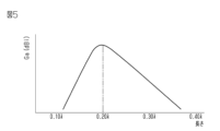
- 2 is a graph showing the relationship between the length of the extension of the parasitic element of FIG. 1 and the gain
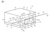
- FIG. 8 is a perspective view showing a transmitter and parasitic elements of a second embodiment
- FIG. 7 is a front view showing the parasitic element of FIG. 6
- 8 is a graph showing the relationship between the length of the extension of the parasitic element of FIG. 7 and the gain
- FIG. 4 is a perspective view showing another example of the parasitic element of the first embodiment
- FIG. 8 is a perspective view showing another example of the parasitic element of the first embodiment
- FIG. 11 is a perspective view showing another parasitic element including a linear element;
- the transmitter has, for example, substantially the same configuration as that of a tire condition monitoring device. That is, it can be said that the transmitter is an existing transmitter.
- the tire condition monitoring device includes transmitters mounted on four wheels of a vehicle and receivers installed on the vehicle. The transmitter is attached to the wheel or tire of the wheel. Also, the transmitter is arranged in the inner space of the tire.
- the transmitter includes a housing, a tire condition detector, a substrate, a transmission circuit, and a loop antenna.
- the housing accommodates the tire condition detector, substrate, transmission circuit and loop antenna.
- the transmitter wirelessly transmits a data signal including tire information detected by the tire condition detector to the receiver using a transmission circuit and a loop antenna.
- a tire condition monitoring device monitors the condition of a tire by having a receiver receive a data signal transmitted from a transmitter.
- the transmitter of the tire condition monitoring device has high environmental resistance performance so that it can withstand the environment inside the tire such as moisture and corrosive gas inside the tire.
- the housing of the transmitter has a sealed structure in order to have high environmental resistance performance.
- the transmitter since the transmitter is attached to the wheel or tire that is constantly subjected to centrifugal force while the vehicle is running, the transmitter is made smaller and lighter.
- the housing In order to reduce the size and weight of the transmitter, the housing is made smaller and the loop antenna is also made smaller.
- a road surface temperature measurement system includes one or more temperature measurement devices with transmitters and one or more receivers. One or more temperature measuring devices are placed outdoors on the road. The temperature measuring device measures the temperature of the road and wirelessly transmits the measured temperature as a data signal from the transmitter to the receiver.
- a transmitter used in a road surface temperature measurement system has a temperature sensor instead of a tire condition detector. A parasitic element used in a transmitter of a road surface temperature measuring system will be described below.
- the transmitter 10 includes a housing 11, a substrate 22, a power supply section 23, and a loop antenna 25.
- Transmitter 10 is configured to transmit data.
- the power supply unit 23 is schematically illustrated, detailed illustration thereof is omitted in FIG. 2 .
- the housing 11 accommodates the board 22 , the feeding section 23 and the loop antenna 25 . That is, the transmitter 10 has the loop antenna 25 inside the housing 11 .
- the housing 11 has a housing body 12 and a flat lid 13 that closes the opening of the housing body 12 .
- the housing body 12 has a first wall 14 and a second wall 15 .
- the first wall 14 is flat.
- the second wall 15 is a rectangular cylindrical peripheral wall.
- a second wall 15 extends from the periphery of the first wall 14 .
- the housing body 12 and the lid 13 are fixed. Due to this fixation, the housing 11 has a closed structure. This sealed structure prevents moisture, gas, and the like from entering the housing 11 from the outside. Therefore, it can be said that the housing 11 has high environmental resistance performance.
- the housing 11 may have a sealed structure by filling the inside of the housing body 12 with resin. In this case, the housing 11 may not have the lid 13 . No external connection terminals for electrical connection or signal connection are provided on the surface of the housing 11 . For this reason, the housing 11 has a structure in which connection from the outside to the internal substrate 22 and the power supply section 23 is impossible.
- the substrate 22 has a plate surface 22a on its surface.
- a power feeding section 23 and a temperature sensor are mounted on the plate surface 22a of the substrate 22 .
- the power supply unit 23 is an electronic component including a transmission circuit (not shown) and a control device.
- the power supply unit 23 modulates the signal detected by the temperature sensor into a radio signal, and then outputs transmission power corresponding to the operating frequency to the loop antenna 25 .
- Usable frequency bands include, for example, the LF band, MF band, HF band, VHF band, UHF band, and 2.4 GHz band.
- the loop antenna 25 as a transmitting antenna is manufactured by bending a metal wire rod, which is an example of a conductor.
- the loop antenna 25 includes a base portion 26 , two extension portions 27 and two terminal connection portions 28 . In order to reduce the size and weight of the transmitter 10, the loop antenna 25 is made as small as possible.
- Each of the two extensions 27 protrudes from each end of the base 26 toward the substrate 22 .
- Each of the two terminal connection portions 28 protrudes from the end of each extension portion 27 located on the opposite side of the base portion 26 so as to approach the terminal connection portions 28 of each other.
- the terminal connection portion 28 of the loop antenna 25 is electrically connected to the feeding portion 23 .
- the loop antenna 25 is fed with power from the feeding section 23 .
- the loop antenna 25 is accommodated in the housing 11 in such a shape that the base 26 is close to the bottom of the housing body 12 and the extended portions 27 protrude from both ends of the base 26 toward the substrate 22 .
- the loop antenna 25 and the substrate 22 define an opening area S2. It can be said that the opening region S2 is a portion surrounded by the loop antenna 25 .
- the opening region S2 is open on the virtual plane 35 along the metal wire.
- the virtual surface 35 is a surface obtained by virtually extending the edge 31 extending along the metal wire so as to surround the opening region S2.
- the loop antenna 25 has an opening surface 36 in a portion surrounded by the loop antenna 25. - ⁇ The opening surface 36 is perpendicular to the plate surface 22 a of the substrate 22 . A straight line perpendicular to the opening surface 36 is defined as a perpendicular line L.
- FIG. Note that the loop antenna 25 may be arranged on the substrate 22 so that the opening surface 36 is oblique to the plate surface 22a.
- the parasitic element 50 is arranged so as to be positioned outside the housing 11 .
- the parasitic element 50 is contactless with respect to the transmitter 10 .
- the parasitic element 50 is arranged so as to be close to the second wall 15 of the housing 11 .
- the parasitic element 50 faces the loop antenna 25 with the second wall 15 interposed therebetween.
- the parasitic element 50 is close to the loop antenna 25 so as to be electromagnetically coupled with the loop antenna 25 .
- Being able to be electromagnetically coupled means that the magnetic field generated by the loop antenna 25 can cause an induced current to flow through the parasitic element 50 .
- the closer the parasitic element 50 is to the loop antenna 25 the better, in order to allow more induced current to flow through the parasitic element 50 due to the magnetic field generated by the loop antenna 25 .
- the parasitic element 50 is made of a metal wire, which is an example of a conductor.
- the parasitic element 50 has a first end 51 and a second end 52 .
- the first end 51 of the parasitic element 50 is one end of the metal wire
- the second end 52 of the parasitic element 50 is the other end of the metal wire.
- the second end 52 is electrically connected to a ground board 70 as a ground.
- the ground substrate 70 has a rectangular plate shape.
- the ground board 70 is made of a conductor.
- a first end 51 of the parasitic element 50 is an open end.
- the parasitic element 50 has a loop portion 53 and an extension portion 61. As shown in FIGS. In addition, the parasitic element 50 may have a connecting portion 54 .
- the parasitic element 50 is formed by bending a metal wire.
- the connecting portion 54 is a portion extending from the loop portion 53 .
- the connecting portion 54 extends vertically.
- the second end 52 is the tip of the connecting portion 54 .
- the connection portion 54 is a portion that connects the loop portion 53 and the ground substrate 70 .
- the connecting portion 54 extends between the ground substrate 70 and the loop portion 53 .
- the loop portion 53 is part of the parasitic element 50 .
- the loop portion 53 is a portion of the parasitic element 50 that is electromagnetically coupled with the loop antenna 25 .
- Loop portion 53 is spaced from first end 51 and second end 52 .
- the loop portion 53 is a portion of the entire metal wire that is bent into a loop shape. When viewed from one direction, the loop portion 53 has a rectangular frame shape.
- the parasitic element 50 is viewed from the front so that the loop portion 53 looks like an oblong frame.
- the loop portion 53 When the parasitic element 50 is viewed from the front, the loop portion 53 defines a rectangular region S3.
- the loop portion 53 has an axis M. As shown in FIG.
- the axis M is a line passing through the center of the region S3 when the parasitic element 50 is viewed from the front.
- the metal wire is bent so that the loop portion 53 has a rectangular frame shape when the parasitic element 50 is viewed from the front.
- the loop portion 53 includes a first side portion 53a, a second side portion 53b, a third side portion 53c, a fourth side portion 53d, and a fifth side portion 53e.
- the first side portion 53a extends vertically from the connection portion 54 when the parasitic element 50 is viewed from the front.
- the second side portion 53b extends between the first side portion 53a and the third side portion 53c.
- the second side portion 53b extends horizontally.
- the third side portion 53c extends between the second side portion 53b and the fourth side portion 53d.
- the third side portion 53c extends vertically.
- the fourth side portion 53d extends between the third side portion 53c and the fifth side portion 53e.
- the fourth side portion 53d extends horizontally.
- the fifth side portion 53e extends vertically from the fourth side portion 53d.
- the first side portion 53a and the third side portion 53c are parallel, and the fifth side portion 53e and the third side portion 53c are parallel. Further, when the parasitic element 50 is viewed from the front, the second side portion 53b and the fourth side portion 53d are parallel to each other.
- the fifth side portion 53e is separated from the first side portion 53a in the direction in which the axis M extends. Therefore, the fourth side portion 53d extends horizontally and obliquely from the third side portion 53c toward the fifth side portion 53e.
- the extension portion 61 is a portion of the parasitic element 50 other than the loop portion 53 and the connection portion 54 and extends from the loop portion 53 .
- the extension portion 61 extends straight in the vertical direction between the first end 51 and the loop portion 53 .
- the parasitic element 50 configured in this manner is arranged outside the housing 11 so that the axis M of the loop portion 53 and the perpendicular L of the loop antenna 25 are parallel. Therefore, when the parasitic element 50 is viewed from the front, the loop portion 53 and the loop antenna 25 appear to overlap each other.
- the gain Ga [dBi] is increased as compared with the case of the loop antenna 25 alone.
- the gain Ga when both the loop antenna 25 and the parasitic element 50 are used is described as the gain Ga of the loop antenna 25.
- FIG. Note that the gain Ga [dBi] is expressed as a multiple of the sensitivity in the direction of maximum sensitivity when the sensitivity of an omnidirectional antenna having uniform sensitivity in all directions is used as a reference.
- the gain Ga of the loop antenna 25 alone was about -12 [dBi]
- the gain Ga of the loop antenna 25 is improved to about 3 to 5 [dBi]. Therefore, the improvement effect, which is a difference from the case of the loop antenna 25 alone, is about 15 to 17 [dB].
- the radio waves from the loop antenna 25 and the extension part 61 are resonated.
- the length of the extension 61 is preferably set to 0.10 ⁇ to 0.40 ⁇ .
- the length of the extension part 61 is around 0.20 ⁇ because the gain Ga is the highest. Considering the resonance characteristics, the ideal length of the extended portion 61 is 0.25 ⁇ . However, the length of the extension 61 is slightly shorter than 0.25 ⁇ . This is because the length of the extension portion 61 becomes shorter than 0.25 ⁇ because the loop portion 53 has an inductance and the phase shifts. Therefore, in this embodiment, it is particularly preferable that the length of the extension portion 61 is 0.20 ⁇ , which is slightly shorter than 0.25 ⁇ . If the length of the extension portion 61 is shorter than 0.10 ⁇ or longer than 0.40 ⁇ , the gain Ga is significantly lowered, which is not preferable.
- the parasitic element 50 having only the extended portion 61 without the loop portion 53 is taken as a comparative example. Compared to this comparative example, the parasitic element 50 having the loop portion 53 is more strongly affected by the magnetic field of the loop antenna 25, so that a larger induced current flows through the loop portion 53 than in the comparative example. Since the energy received from the loop antenna 25 can be efficiently radiated using the extension part 61, the transmission output from the transmitter 10 can be reduced compared to the case where the energy is radiated as radio waves from the loop antenna 25 alone. can be raised. If the amount of power supplied to the loop antenna 25 is the same, the communication distance from the transmitter 10 can be extended.
- the transmitter 10 is an existing transmitter that can also be used as a transmitter for a tire condition monitoring device. Further, the housing 11 of the transmitter 10 has a sealed structure, and the housing 11 and the loop antenna 25 are miniaturized. When a transmitter that can be used as a transmitter of a tire condition monitoring device is used alone as the transmitter 10 of a road surface temperature measurement system, its transmission output may be insufficient. In this case, by simply arranging the parasitic element 50 outside the housing 11, the transmitter can be obtained without changing the hardware including the loop antenna 25 and without adding a device that requires a power supply. 10 transmission power can be increased.
- the parasitic element 50 has one extended portion 61 having the first end 51 as an open end. A second end 52 of the parasitic element 50 is connected to the ground substrate 70 . For the same transmission output, the length of the parasitic element 50 can be shortened compared to the case where the parasitic element 50 has two extension portions 61 .
- the length of the extended portion 61 is set to 0.10 ⁇ to 0.40 ⁇ . Since the length of the extension portion 61 is defined, the radio wave from the loop antenna 25 and the extension portion 61 are easily resonated. Therefore, the gain Ga of the loop antenna 25 using the parasitic element 50 can be increased as compared with the case of the loop antenna 25 alone.
- the parasitic element 50 has one extended portion 61 with the first end 51 as an open end, and is not electrically connected to the feeding portion 23 . Compared to the case where the parasitic element 50 having such an open end is directly electrically connected to the transmitter 10, the effects of lightning strikes on the loop antenna 25 and static electricity on the transmission circuit can be reduced.
- the parasitic element 50 has two extensions 61 so as to have two open ends on both sides of the loop portion 53 .
- the two extensions 61 extend in opposite directions from the loop portion 53 so as to be positioned on both sides of the loop portion 53 .
- One extension 61 has a first end 51 at its tip, and the other extension 61 has a second end 52 at its tip.
- Each of the two extensions 61 is straight.
- One extension portion 61 extends between the first end 51 and the loop portion 53 .
- the other extension 61 extends between the second end 52 and the loop portion 53 .
- the two extensions 61 have the same length.
- the loop portion 53 is sandwiched between two extension portions 61 .
- the loop portion 53 includes a first side portion 53a, a second side portion 53b, a third side portion 53c, a fourth side portion 53d, and a fifth side portion 53e.
- the first side portion 53 a is positioned between the two extension portions 61 when the parasitic element 50 is viewed from the front.
- the first side portion 53a extends horizontally.
- One extension portion 61 extends from the first side portion 53a.
- the first side portion 53a and one extension portion 61 extend linearly.
- the second side portion 53b extends between the first side portion 53a and the third side portion 53c.
- the second side portion 53b extends vertically.
- the third side portion 53c extends between the second side portion 53b and the fourth side portion 53d.
- the third side portion 53c extends horizontally.
- the fourth side portion 53d extends between the third side portion 53c and the fifth side portion 53e.
- the fourth side portion 53d extends vertically.
- the fifth side portion 53e extends horizontally from the fourth side portion 53d.
- Another extension 61 extends from the fifth side 53e.
- the fifth side portion 53e and another extension portion 61 extend linearly.
- the first side portion 53a and the third side portion 53c are parallel.
- the second side portion 53b and the fourth side portion 53d are parallel to each other.
- the first side portion 53a and the fifth side portion 53e face the base portion 26 of the loop antenna 25 with the second wall 15 interposed therebetween.
- the second side portion 53b faces one extension portion 27 with the second wall 15 interposed therebetween, and the fourth side portion 53d faces the other extension portion 27 with the second wall 15 interposed therebetween.
- the third side portion 53c faces two terminal connection portions 28 of the loop antenna 25 with the second wall 15 interposed therebetween.
- the size of the rectangular frame of the loop portion 53 in front view of the parasitic element 50 is substantially the same as the size of the rectangular frame of the loop antenna 25 .
- the parasitic element 50 configured in this manner is arranged so that the axis M of the loop portion 53 and the perpendicular L of the loop antenna 25 are parallel.
- Extension part The length from the loop portion 53 to the ends 51 and 52 is the length of each extension portion 61 .
- the radio waves from the loop antenna 25 and the extension part 61 are resonated.
- the length of the extension 61 is preferably 0.19 ⁇ to 0.25 ⁇ in order to make the extension 61 resonate. It can be said that the total length of the two extensions 61 of the parasitic element 50 is preferably 0.38 ⁇ to 0.50 ⁇ .
- each extension part 61 is around 0.22 ⁇ because the gain Ga is maximized. If the length of the extension portion 61 is less than 0.19 ⁇ or more than 0.25 ⁇ , the gain Ga is significantly lowered, which is not preferable.
- the second embodiment also has the following effects.
- the length of the extended portion 61 is set to 0.19 ⁇ to 0.25 ⁇ . Therefore, it becomes easier to cause the extension portion 61 to resonate with the radio waves from the loop antenna 25 . Therefore, the gain Ga of the loop antenna 25 using the parasitic element 50 can be increased as compared with the case of the loop antenna 25 alone.
- the parasitic element 50 has an extension portion 61 with the first end 51 as an open end and an extension portion 61 with the second end 52 as an open end. Compared to the case where the parasitic element 50 having such an open end is directly electrically connected to the transmitter 10, the effects of lightning strikes on the loop antenna 25 and static electricity on the transmission circuit can be reduced.
- the extension portion 61 may be bent to include a first straight portion 63 and a second straight portion 64 .
- the first straight portion 63 extends between the loop portion 53 and the second straight portion 64 when the parasitic element 50 is viewed from the front.
- the first straight portion 63 extends vertically.
- the first straight portion 63 extends between the fifth side portion 53 e of the loop portion 53 and the second straight portion 64 .
- the second straight portion 64 extends straight from the first straight portion 63 .
- the second straight portion 64 extends horizontally.
- the first end 51 is the tip of the second linear portion 64 .
- the extension 61 has the first end 51 as an open end. It can be said that the parasitic element 50 has one extension 61 so as to have one open end.
- the lengths of the first straight portion 63 and the second straight portion 64 may be different. Unlike the first embodiment, bending the extension part 61 slightly shifts the resonance characteristics with respect to the operating frequency and changes the gain Ga. Can be made smaller.
- the shape of the extension portion 61 may be changed as appropriate, such as a zigzag shape such as a so-called meander line, or a spiral shape, in addition to the shapes disclosed in the first and second embodiments. good too. Also, the shape of the extension part 61 may be appropriately changed according to the space around the transmitter 10 and the arrangement of articles around the transmitter 10 . Furthermore, the shape of the extension part 61 may be changed so as to follow the surface of the housing 11 of the transmitter 10 .
- the extension portion 61 may include a first straight portion 63 , a second straight portion 64 , a third straight portion 65 and a fourth straight portion 66 .
- the first straight portion 63 extends between the loop portion 53 and the second straight portion 64 when the parasitic element 50 is viewed from the front.
- the first straight portion 63 extends vertically.
- the first straight portion 63 extends between the fifth side portion 53 e of the loop portion 53 and the second straight portion 64 .
- the second straight portion 64 extends between the first straight portion 63 and the third straight portion 65 .
- the second straight portion 64 extends horizontally.
- the third straight portion 65 extends between the second straight portion 64 and the fourth straight portion 66 .
- the third straight portion 65 extends horizontally.
- the fourth straight portion 66 extends from the third straight portion 65 .
- the fourth straight portion 66 extends horizontally.
- the second linear portion 64 and the fourth linear portion 66 are parallel.
- the first end 51 is the tip of the fourth linear portion 66 .
- the extension 61 has the first end 51 as an open end. It can be said that the parasitic element 50 has one extension 61 so as to have one open end.
- the extension portion 61 is bent so as to have a first straight portion 63, a second straight portion 64, a third straight portion 65, and a fourth straight portion 66 in order to reduce the size.
- a parasitic element 91 may include the parasitic element 50 of the second embodiment and the linear element 90 .
- the linear element 90 is made of metal wire.
- Linear element 90 is linear.
- Linear element 90 is arranged side by side with extensions 61 along the direction in which axis line M extends so as to be parallel to each of two extensions 61 of parasitic element 50 .
- the length of the linear element 90 is preferably around 0.50 ⁇ , particularly preferably slightly shorter than 0.50 ⁇ , in order to increase the improvement effect [dB].
- the linear element 90 is arranged parallel to the aperture plane 36 of the loop antenna 25 .
- the linear element 90 is preferably arranged at a distance of approximately 0.10 ⁇ from the loop antenna 25 .
- the linear element 90 can function as a waveguide that draws out the energy radiated from the parasitic element 50 . Therefore, in the parasitic element 91 including the linear element 90 , the directivity of radio waves radiated from the parasitic element 50 adjacent to the loop antenna 25 can be enhanced by the linear element 90 . As a result, the gain Ga of the loop antenna 25 using the parasitic element 91 can be increased as compared with the case of the loop antenna 25 alone.
- the linear element 90 may be arranged not parallel to each of the two extensions 61 of the parasitic element 50 but slightly inclined.
- the linear element 90 may be formed of a metal processed product using a metal wire or a metal plate, or may be formed of a conductor pattern provided on a printed board or flexible board.
- the linear element 90 may be formed of lead wires including single wires and stranded wires, or may be formed of a conductive resin or conductive rubber material.
- the parasitic element 91 may include the parasitic element 50 of the first embodiment and the linear element 90 .
- the linear element 90 is arranged to extend in the vertical direction so as to be parallel to the extension 61 of the parasitic element 50 .
- the parasitic element 91 may include the parasitic element 50 shown in FIG. 9 and the linear element 90 .
- the linear element 90 is preferably arranged side by side with the extension 61 so as to be parallel to the second linear portion 64 of the extension 61 .
- the size of the rectangular frame of the loop portion 53 may be smaller or larger than the size of the rectangular frame of the loop antenna 25 . In other words, when the parasitic element 50 is viewed from the front, the loop portion 53 and the loop antenna 25 do not need to overlap each other.
- At least one of the first side portion 53 a to the fifth side portion 53 e of the loop portion 53 may overlap the loop antenna 25 .
- the loop antenna 25 and the parasitic element 50 are formed of a metal wire as a conductor, they are not limited to this.
- the materials of the loop antenna 25 and the parasitic element 50 are not limited as long as they are conductors.
- the loop antenna 25 and the parasitic element 50 may be formed of metal products using metal wires or metal plates, or may be formed of conductor patterns provided on printed boards or flexible boards.
- loop antenna 25 and parasitic element 50 may be formed of lead wires including single wires and twisted wires, or may be formed of conductive resin or conductive rubber material.
- the loop antenna 25 and the parasitic element 50 may be formed by plating the housing 11 made of resin or ceramic or by patterning conductive paint.
- the electronic component provided on the substrate 22 of the transmitter 10 may be any electronic component such as a pressure sensor.
- the transmitter 10 may be used as a transmitter for a system other than the road surface temperature measurement system.
- the loop antenna 25 may be manufactured by bending a single rectangular leaf spring.
- loop antenna 25 is made of stainless steel, which is an example of a conductor.
- the loop antenna 25 has a base portion 26 , two extension portions 27 and two terminal connection portions 28 .
- Each of the base portion 26, the extension portion 27, and the terminal connection portion 28 has a long plate shape.
Landscapes
- Details Of Aerials (AREA)
- Transmitters (AREA)
Priority Applications (5)
| Application Number | Priority Date | Filing Date | Title |
|---|---|---|---|
| US18/282,134 US20240178562A1 (en) | 2021-09-06 | 2021-09-06 | Non-powered element |
| EP21956072.9A EP4304013A4 (en) | 2021-09-06 | 2021-09-06 | ELEMENT NOT POWERED |
| CN202180095845.1A CN117099267A (zh) | 2021-09-06 | 2021-09-06 | 无源元件 |
| JP2023544963A JP7607142B2 (ja) | 2021-09-06 | 2021-09-06 | 無給電素子 |
| PCT/JP2021/032610 WO2023032186A1 (ja) | 2021-09-06 | 2021-09-06 | 無給電素子 |
Applications Claiming Priority (1)
| Application Number | Priority Date | Filing Date | Title |
|---|---|---|---|
| PCT/JP2021/032610 WO2023032186A1 (ja) | 2021-09-06 | 2021-09-06 | 無給電素子 |
Publications (1)
| Publication Number | Publication Date |
|---|---|
| WO2023032186A1 true WO2023032186A1 (ja) | 2023-03-09 |
Family
ID=85411043
Family Applications (1)
| Application Number | Title | Priority Date | Filing Date |
|---|---|---|---|
| PCT/JP2021/032610 Ceased WO2023032186A1 (ja) | 2021-09-06 | 2021-09-06 | 無給電素子 |
Country Status (5)
| Country | Link |
|---|---|
| US (1) | US20240178562A1 (https=) |
| EP (1) | EP4304013A4 (https=) |
| JP (1) | JP7607142B2 (https=) |
| CN (1) | CN117099267A (https=) |
| WO (1) | WO2023032186A1 (https=) |
Citations (5)
| Publication number | Priority date | Publication date | Assignee | Title |
|---|---|---|---|---|
| JPS62139112U (https=) * | 1986-02-24 | 1987-09-02 | ||
| JPH11340731A (ja) * | 1998-05-27 | 1999-12-10 | Toa Corp | 無給電アンテナ |
| JP2001284946A (ja) * | 2000-03-30 | 2001-10-12 | Ntt Docomo Inc | 広帯域アンテナ及びアレイアンテナ装置 |
| JP2015035644A (ja) | 2013-08-07 | 2015-02-19 | 株式会社日本自動車部品総合研究所 | アンテナ装置 |
| WO2018199007A1 (ja) * | 2017-04-28 | 2018-11-01 | 株式会社村田製作所 | Rfidタグ |
Family Cites Families (10)
| Publication number | Priority date | Publication date | Assignee | Title |
|---|---|---|---|---|
| WO2002071536A1 (en) * | 2001-03-02 | 2002-09-12 | Motorola, Inc., A Corporation Of The State Of Delaware | Parasitic antenna element and wireless communication device incorporating the same |
| US6765536B2 (en) * | 2002-05-09 | 2004-07-20 | Motorola, Inc. | Antenna with variably tuned parasitic element |
| US6888511B2 (en) * | 2002-09-09 | 2005-05-03 | Brian Victor Cake | Physically small antenna elements and antennas based thereon |
| US9941588B2 (en) * | 2007-08-20 | 2018-04-10 | Ethertronics, Inc. | Antenna with multiple coupled regions |
| US9838060B2 (en) * | 2011-11-02 | 2017-12-05 | Antenna79, Inc. | Protective cover for a wireless device |
| TWI566474B (zh) * | 2014-05-09 | 2017-01-11 | 環旭電子股份有限公司 | 多頻天線 |
| WO2016138480A1 (en) * | 2015-02-27 | 2016-09-01 | Bringuier Jonathan Neil | Closely coupled re-radiator compound loop antenna structure |
| GB2553093B (en) * | 2016-08-17 | 2019-05-15 | Drayson Tech Europe Ltd | RF energy harvesting dual loop antenna with gaps and bridges |
| TWI638485B (zh) * | 2017-10-05 | 2018-10-11 | 廣達電腦股份有限公司 | 穿戴式裝置 |
| JP7157970B2 (ja) * | 2019-07-19 | 2022-10-21 | 大王製紙株式会社 | Rfidタグ及びアンテナ |
-
2021
- 2021-09-06 EP EP21956072.9A patent/EP4304013A4/en not_active Withdrawn
- 2021-09-06 CN CN202180095845.1A patent/CN117099267A/zh active Pending
- 2021-09-06 US US18/282,134 patent/US20240178562A1/en not_active Abandoned
- 2021-09-06 JP JP2023544963A patent/JP7607142B2/ja active Active
- 2021-09-06 WO PCT/JP2021/032610 patent/WO2023032186A1/ja not_active Ceased
Patent Citations (5)
| Publication number | Priority date | Publication date | Assignee | Title |
|---|---|---|---|---|
| JPS62139112U (https=) * | 1986-02-24 | 1987-09-02 | ||
| JPH11340731A (ja) * | 1998-05-27 | 1999-12-10 | Toa Corp | 無給電アンテナ |
| JP2001284946A (ja) * | 2000-03-30 | 2001-10-12 | Ntt Docomo Inc | 広帯域アンテナ及びアレイアンテナ装置 |
| JP2015035644A (ja) | 2013-08-07 | 2015-02-19 | 株式会社日本自動車部品総合研究所 | アンテナ装置 |
| WO2018199007A1 (ja) * | 2017-04-28 | 2018-11-01 | 株式会社村田製作所 | Rfidタグ |
Non-Patent Citations (1)
| Title |
|---|
| See also references of EP4304013A4 |
Also Published As
| Publication number | Publication date |
|---|---|
| US20240178562A1 (en) | 2024-05-30 |
| JP7607142B2 (ja) | 2024-12-26 |
| EP4304013A1 (en) | 2024-01-10 |
| CN117099267A (zh) | 2023-11-21 |
| EP4304013A4 (en) | 2024-07-17 |
| JPWO2023032186A1 (https=) | 2023-03-09 |
Similar Documents
| Publication | Publication Date | Title |
|---|---|---|
| US4724443A (en) | Patch antenna with a strip line feed element | |
| EP2502309B1 (en) | Slot halo antenna device | |
| Iqbal et al. | Slot-DRA-based independent dual-band hybrid antenna for wearable biomedical devices | |
| US20120313824A1 (en) | Radio device | |
| US20160301127A1 (en) | Mobile radio device | |
| CN103081220A (zh) | 天线装置及无线通信机 | |
| US20260031661A1 (en) | Power receiving antenna | |
| US11984656B2 (en) | RF tag antenna, RF tag, tire provided with RF tag, and tire with built-in RF tag | |
| AU2013275529B2 (en) | Condition detection device | |
| JP4125118B2 (ja) | 広帯域内蔵型アンテナ | |
| US6927730B2 (en) | Radiation device with a L-shaped ground plane | |
| JP7607142B2 (ja) | 無給電素子 | |
| US20130043315A1 (en) | RFID tag with open-cavity antenna structure | |
| JP7556159B2 (ja) | アンテナユニットおよび送信機 | |
| US20060145925A1 (en) | Planar inverted-F antenna | |
| JP3560783B2 (ja) | 自動検針用無線装置 | |
| WO2015108033A1 (ja) | アンテナ装置及びそれを備える無線装置 | |
| JP7031924B2 (ja) | Rfidタグのリーダライタ用のスロットアンテナ、および、rfidタグ用リーダライタ装置 | |
| CN118120110A (zh) | 用于无线麦克风应用的麦克风天线 | |
| JP2019047328A (ja) | アンテナ及び通信装置 | |
| CN108155470B (zh) | 一种天线装置以及移动通信设备 | |
| CN205646140U (zh) | 天线模块 | |
| EP3024091A1 (en) | Wireless apparatus | |
| AU767408B2 (en) | Antennas for portable communications devices | |
| WO2023002906A1 (ja) | 無線電力伝送システムおよび受電器 |
Legal Events
| Date | Code | Title | Description |
|---|---|---|---|
| 121 | Ep: the epo has been informed by wipo that ep was designated in this application |
Ref document number: 21956072 Country of ref document: EP Kind code of ref document: A1 |
|
| WWE | Wipo information: entry into national phase |
Ref document number: 2023544963 Country of ref document: JP |
|
| WWE | Wipo information: entry into national phase |
Ref document number: 18282134 Country of ref document: US |
|
| WWE | Wipo information: entry into national phase |
Ref document number: 202180095845.1 Country of ref document: CN |
|
| WWE | Wipo information: entry into national phase |
Ref document number: 2021956072 Country of ref document: EP |
|
| ENP | Entry into the national phase |
Ref document number: 2021956072 Country of ref document: EP Effective date: 20231004 |
|
| NENP | Non-entry into the national phase |
Ref country code: DE |
|
| WWW | Wipo information: withdrawn in national office |
Ref document number: 2021956072 Country of ref document: EP |