WO2023032186A1 - Non-powered element - Google Patents
Non-powered element Download PDFInfo
- Publication number
- WO2023032186A1 WO2023032186A1 PCT/JP2021/032610 JP2021032610W WO2023032186A1 WO 2023032186 A1 WO2023032186 A1 WO 2023032186A1 JP 2021032610 W JP2021032610 W JP 2021032610W WO 2023032186 A1 WO2023032186 A1 WO 2023032186A1
- Authority
- WO
- WIPO (PCT)
- Prior art keywords
- parasitic element
- loop antenna
- loop
- extension
- transmitter
- Prior art date
Links
- 230000003071 parasitic effect Effects 0.000 claims description 120
- 230000005540 biological transmission Effects 0.000 description 18
- 239000002184 metal Substances 0.000 description 17
- 239000000758 substrate Substances 0.000 description 17
- 239000004020 conductor Substances 0.000 description 8
- 238000009529 body temperature measurement Methods 0.000 description 6
- 238000012806 monitoring device Methods 0.000 description 6
- 238000005452 bending Methods 0.000 description 5
- 230000000052 comparative effect Effects 0.000 description 5
- 230000000694 effects Effects 0.000 description 5
- 230000005684 electric field Effects 0.000 description 4
- 239000011347 resin Substances 0.000 description 4
- 229920005989 resin Polymers 0.000 description 4
- 230000035945 sensitivity Effects 0.000 description 4
- 230000007613 environmental effect Effects 0.000 description 3
- 239000000463 material Substances 0.000 description 3
- 206010042255 Struck by lightning Diseases 0.000 description 2
- 238000004891 communication Methods 0.000 description 2
- 230000005611 electricity Effects 0.000 description 2
- 230000003068 static effect Effects 0.000 description 2
- 240000001973 Ficus microcarpa Species 0.000 description 1
- 238000013459 approach Methods 0.000 description 1
- 239000000919 ceramic Substances 0.000 description 1
- 230000008878 coupling Effects 0.000 description 1
- 238000010168 coupling process Methods 0.000 description 1
- 238000005859 coupling reaction Methods 0.000 description 1
- 238000012986 modification Methods 0.000 description 1
- 230000004048 modification Effects 0.000 description 1
- 239000003973 paint Substances 0.000 description 1
- 238000000059 patterning Methods 0.000 description 1
- 230000002093 peripheral effect Effects 0.000 description 1
- 230000010363 phase shift Effects 0.000 description 1
- 238000007747 plating Methods 0.000 description 1
- 229910001220 stainless steel Inorganic materials 0.000 description 1
- 239000010935 stainless steel Substances 0.000 description 1
Images


Classifications
-
- H—ELECTRICITY
- H01—ELECTRIC ELEMENTS
- H01Q—ANTENNAS, i.e. RADIO AERIALS
- H01Q1/00—Details of, or arrangements associated with, antennas
- H01Q1/27—Adaptation for use in or on movable bodies
- H01Q1/32—Adaptation for use in or on road or rail vehicles
- H01Q1/3208—Adaptation for use in or on road or rail vehicles characterised by the application wherein the antenna is used
- H01Q1/3233—Adaptation for use in or on road or rail vehicles characterised by the application wherein the antenna is used particular used as part of a sensor or in a security system, e.g. for automotive radar, navigation systems
- H01Q1/3241—Adaptation for use in or on road or rail vehicles characterised by the application wherein the antenna is used particular used as part of a sensor or in a security system, e.g. for automotive radar, navigation systems particular used in keyless entry systems
-
- H—ELECTRICITY
- H01—ELECTRIC ELEMENTS
- H01Q—ANTENNAS, i.e. RADIO AERIALS
- H01Q1/00—Details of, or arrangements associated with, antennas
- H01Q1/27—Adaptation for use in or on movable bodies
- H01Q1/32—Adaptation for use in or on road or rail vehicles
- H01Q1/325—Adaptation for use in or on road or rail vehicles characterised by the location of the antenna on the vehicle
- H01Q1/3291—Adaptation for use in or on road or rail vehicles characterised by the location of the antenna on the vehicle mounted in or on other locations inside the vehicle or vehicle body
-
- H—ELECTRICITY
- H01—ELECTRIC ELEMENTS
- H01Q—ANTENNAS, i.e. RADIO AERIALS
- H01Q7/00—Loop antennas with a substantially uniform current distribution around the loop and having a directional radiation pattern in a plane perpendicular to the plane of the loop
-
- H—ELECTRICITY
- H01—ELECTRIC ELEMENTS
- H01Q—ANTENNAS, i.e. RADIO AERIALS
- H01Q9/00—Electrically-short antennas having dimensions not more than twice the operating wavelength and consisting of conductive active radiating elements
- H01Q9/04—Resonant antennas
- H01Q9/16—Resonant antennas with feed intermediate between the extremities of the antenna, e.g. centre-fed dipole
-
- H—ELECTRICITY
- H01—ELECTRIC ELEMENTS
- H01Q—ANTENNAS, i.e. RADIO AERIALS
- H01Q9/00—Electrically-short antennas having dimensions not more than twice the operating wavelength and consisting of conductive active radiating elements
- H01Q9/04—Resonant antennas
- H01Q9/30—Resonant antennas with feed to end of elongated active element, e.g. unipole
Definitions
- the present disclosure relates to parasitic elements used in transmitters.
- a transmitter configured to transmit data comprises a transmitting antenna for transmitting data.
- Patent Literature 1 discloses that an antenna device, which is a transmitting antenna, is built in a case of a portable device as a transmitter.
- the portable device of Patent Document 1 is a transmitter used in a vehicle keyless system.
- Patent Document 1 When trying to use the portable device disclosed in Patent Document 1 as a transmitter in another system, that is, when trying to use an existing transmitter for another purpose. At this time, if the transmission output of the transmitter is insufficient, it is desirable to increase the transmission output without changing the hardware including the transmitting antenna of the transmitter or adding a device that requires a power supply.
- a parasitic element for use in a transmitter configured to transmit data, the transmitter comprising: a powered loop antenna; , wherein the parasitic element arranged to be positioned outside the housing includes a loop portion that is a part of the parasitic element and an extension that is a portion other than the loop portion and extends from the loop portion and a portion, wherein the loop portion is configured to be electromagnetically coupled with the loop antenna, and the extension portion has at least one end of the parasitic element as an open end.
- the transmission output from the transmitter can be increased. If the transmission power to the loop antenna is the same, the communication distance from the transmitter can be extended. Therefore, even with an existing transmitter, simply by adding a parasitic element to the outside of the housing, the device that requires a power supply can be used without changing the hardware including the loop antenna of the transmitter. The transmit power of the transmitter can be increased without adding anything.
- the parasitic element has one extension portion and one open end, and the parasitic element is configured to be connected to the first end, which is the open end, and to the ground. and a second end.
- the extension portion may have a length of 0.10 ⁇ to 0.40 ⁇ , where ⁇ is the wavelength at the operating frequency of the loop antenna.
- the extension may include two extensions located on both sides of the loop, and each of the two extensions may have the open end.
- the two extension portions may have a length of 0.19 ⁇ to 0.25 ⁇ , where ⁇ is the wavelength at the operating frequency of the loop antenna.
- the parasitic element may further include a linear element arranged side by side with the extension.
- FIG. 1 is a perspective view showing a transmitter and parasitic elements of the first embodiment
- FIG. 2 is an end view showing the interior of the transmitter of FIG. 1 and a parasitic element
- FIG. 2 is an exploded perspective view showing the transmitter of FIG. 1
- FIG. FIG. 2 is a front view showing the parasitic element and transmitter of FIG. 1
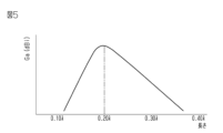
- 2 is a graph showing the relationship between the length of the extension of the parasitic element of FIG. 1 and the gain
- FIG. 8 is a perspective view showing a transmitter and parasitic elements of a second embodiment
- FIG. 7 is a front view showing the parasitic element of FIG. 6
- 8 is a graph showing the relationship between the length of the extension of the parasitic element of FIG. 7 and the gain
- FIG. 4 is a perspective view showing another example of the parasitic element of the first embodiment
- FIG. 8 is a perspective view showing another example of the parasitic element of the first embodiment
- FIG. 11 is a perspective view showing another parasitic element including a linear element;
- the transmitter has, for example, substantially the same configuration as that of a tire condition monitoring device. That is, it can be said that the transmitter is an existing transmitter.
- the tire condition monitoring device includes transmitters mounted on four wheels of a vehicle and receivers installed on the vehicle. The transmitter is attached to the wheel or tire of the wheel. Also, the transmitter is arranged in the inner space of the tire.
- the transmitter includes a housing, a tire condition detector, a substrate, a transmission circuit, and a loop antenna.
- the housing accommodates the tire condition detector, substrate, transmission circuit and loop antenna.
- the transmitter wirelessly transmits a data signal including tire information detected by the tire condition detector to the receiver using a transmission circuit and a loop antenna.
- a tire condition monitoring device monitors the condition of a tire by having a receiver receive a data signal transmitted from a transmitter.
- the transmitter of the tire condition monitoring device has high environmental resistance performance so that it can withstand the environment inside the tire such as moisture and corrosive gas inside the tire.
- the housing of the transmitter has a sealed structure in order to have high environmental resistance performance.
- the transmitter since the transmitter is attached to the wheel or tire that is constantly subjected to centrifugal force while the vehicle is running, the transmitter is made smaller and lighter.
- the housing In order to reduce the size and weight of the transmitter, the housing is made smaller and the loop antenna is also made smaller.
- a road surface temperature measurement system includes one or more temperature measurement devices with transmitters and one or more receivers. One or more temperature measuring devices are placed outdoors on the road. The temperature measuring device measures the temperature of the road and wirelessly transmits the measured temperature as a data signal from the transmitter to the receiver.
- a transmitter used in a road surface temperature measurement system has a temperature sensor instead of a tire condition detector. A parasitic element used in a transmitter of a road surface temperature measuring system will be described below.
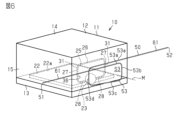
- the transmitter 10 includes a housing 11, a substrate 22, a power supply section 23, and a loop antenna 25.
- Transmitter 10 is configured to transmit data.
- the power supply unit 23 is schematically illustrated, detailed illustration thereof is omitted in FIG. 2 .
- the housing 11 accommodates the board 22 , the feeding section 23 and the loop antenna 25 . That is, the transmitter 10 has the loop antenna 25 inside the housing 11 .
- the housing 11 has a housing body 12 and a flat lid 13 that closes the opening of the housing body 12 .
- the housing body 12 has a first wall 14 and a second wall 15 .
- the first wall 14 is flat.
- the second wall 15 is a rectangular cylindrical peripheral wall.
- a second wall 15 extends from the periphery of the first wall 14 .
- the housing body 12 and the lid 13 are fixed. Due to this fixation, the housing 11 has a closed structure. This sealed structure prevents moisture, gas, and the like from entering the housing 11 from the outside. Therefore, it can be said that the housing 11 has high environmental resistance performance.
- the housing 11 may have a sealed structure by filling the inside of the housing body 12 with resin. In this case, the housing 11 may not have the lid 13 . No external connection terminals for electrical connection or signal connection are provided on the surface of the housing 11 . For this reason, the housing 11 has a structure in which connection from the outside to the internal substrate 22 and the power supply section 23 is impossible.
- the substrate 22 has a plate surface 22a on its surface.
- a power feeding section 23 and a temperature sensor are mounted on the plate surface 22a of the substrate 22 .
- the power supply unit 23 is an electronic component including a transmission circuit (not shown) and a control device.
- the power supply unit 23 modulates the signal detected by the temperature sensor into a radio signal, and then outputs transmission power corresponding to the operating frequency to the loop antenna 25 .
- Usable frequency bands include, for example, the LF band, MF band, HF band, VHF band, UHF band, and 2.4 GHz band.
- the loop antenna 25 as a transmitting antenna is manufactured by bending a metal wire rod, which is an example of a conductor.
- the loop antenna 25 includes a base portion 26 , two extension portions 27 and two terminal connection portions 28 . In order to reduce the size and weight of the transmitter 10, the loop antenna 25 is made as small as possible.
- Each of the two extensions 27 protrudes from each end of the base 26 toward the substrate 22 .
- Each of the two terminal connection portions 28 protrudes from the end of each extension portion 27 located on the opposite side of the base portion 26 so as to approach the terminal connection portions 28 of each other.
- the terminal connection portion 28 of the loop antenna 25 is electrically connected to the feeding portion 23 .
- the loop antenna 25 is fed with power from the feeding section 23 .
- the loop antenna 25 is accommodated in the housing 11 in such a shape that the base 26 is close to the bottom of the housing body 12 and the extended portions 27 protrude from both ends of the base 26 toward the substrate 22 .
- the loop antenna 25 and the substrate 22 define an opening area S2. It can be said that the opening region S2 is a portion surrounded by the loop antenna 25 .
- the opening region S2 is open on the virtual plane 35 along the metal wire.
- the virtual surface 35 is a surface obtained by virtually extending the edge 31 extending along the metal wire so as to surround the opening region S2.
- the loop antenna 25 has an opening surface 36 in a portion surrounded by the loop antenna 25. - ⁇ The opening surface 36 is perpendicular to the plate surface 22 a of the substrate 22 . A straight line perpendicular to the opening surface 36 is defined as a perpendicular line L.
- FIG. Note that the loop antenna 25 may be arranged on the substrate 22 so that the opening surface 36 is oblique to the plate surface 22a.
- the parasitic element 50 is arranged so as to be positioned outside the housing 11 .
- the parasitic element 50 is contactless with respect to the transmitter 10 .
- the parasitic element 50 is arranged so as to be close to the second wall 15 of the housing 11 .
- the parasitic element 50 faces the loop antenna 25 with the second wall 15 interposed therebetween.
- the parasitic element 50 is close to the loop antenna 25 so as to be electromagnetically coupled with the loop antenna 25 .
- Being able to be electromagnetically coupled means that the magnetic field generated by the loop antenna 25 can cause an induced current to flow through the parasitic element 50 .
- the closer the parasitic element 50 is to the loop antenna 25 the better, in order to allow more induced current to flow through the parasitic element 50 due to the magnetic field generated by the loop antenna 25 .
- the parasitic element 50 is made of a metal wire, which is an example of a conductor.
- the parasitic element 50 has a first end 51 and a second end 52 .
- the first end 51 of the parasitic element 50 is one end of the metal wire
- the second end 52 of the parasitic element 50 is the other end of the metal wire.
- the second end 52 is electrically connected to a ground board 70 as a ground.
- the ground substrate 70 has a rectangular plate shape.
- the ground board 70 is made of a conductor.
- a first end 51 of the parasitic element 50 is an open end.
- the parasitic element 50 has a loop portion 53 and an extension portion 61. As shown in FIGS. In addition, the parasitic element 50 may have a connecting portion 54 .
- the parasitic element 50 is formed by bending a metal wire.
- the connecting portion 54 is a portion extending from the loop portion 53 .
- the connecting portion 54 extends vertically.
- the second end 52 is the tip of the connecting portion 54 .
- the connection portion 54 is a portion that connects the loop portion 53 and the ground substrate 70 .
- the connecting portion 54 extends between the ground substrate 70 and the loop portion 53 .
- the loop portion 53 is part of the parasitic element 50 .
- the loop portion 53 is a portion of the parasitic element 50 that is electromagnetically coupled with the loop antenna 25 .
- Loop portion 53 is spaced from first end 51 and second end 52 .
- the loop portion 53 is a portion of the entire metal wire that is bent into a loop shape. When viewed from one direction, the loop portion 53 has a rectangular frame shape.
- the parasitic element 50 is viewed from the front so that the loop portion 53 looks like an oblong frame.
- the loop portion 53 When the parasitic element 50 is viewed from the front, the loop portion 53 defines a rectangular region S3.
- the loop portion 53 has an axis M. As shown in FIG.
- the axis M is a line passing through the center of the region S3 when the parasitic element 50 is viewed from the front.
- the metal wire is bent so that the loop portion 53 has a rectangular frame shape when the parasitic element 50 is viewed from the front.
- the loop portion 53 includes a first side portion 53a, a second side portion 53b, a third side portion 53c, a fourth side portion 53d, and a fifth side portion 53e.
- the first side portion 53a extends vertically from the connection portion 54 when the parasitic element 50 is viewed from the front.
- the second side portion 53b extends between the first side portion 53a and the third side portion 53c.
- the second side portion 53b extends horizontally.
- the third side portion 53c extends between the second side portion 53b and the fourth side portion 53d.
- the third side portion 53c extends vertically.
- the fourth side portion 53d extends between the third side portion 53c and the fifth side portion 53e.
- the fourth side portion 53d extends horizontally.
- the fifth side portion 53e extends vertically from the fourth side portion 53d.
- the first side portion 53a and the third side portion 53c are parallel, and the fifth side portion 53e and the third side portion 53c are parallel. Further, when the parasitic element 50 is viewed from the front, the second side portion 53b and the fourth side portion 53d are parallel to each other.
- the fifth side portion 53e is separated from the first side portion 53a in the direction in which the axis M extends. Therefore, the fourth side portion 53d extends horizontally and obliquely from the third side portion 53c toward the fifth side portion 53e.
- the extension portion 61 is a portion of the parasitic element 50 other than the loop portion 53 and the connection portion 54 and extends from the loop portion 53 .
- the extension portion 61 extends straight in the vertical direction between the first end 51 and the loop portion 53 .
- the parasitic element 50 configured in this manner is arranged outside the housing 11 so that the axis M of the loop portion 53 and the perpendicular L of the loop antenna 25 are parallel. Therefore, when the parasitic element 50 is viewed from the front, the loop portion 53 and the loop antenna 25 appear to overlap each other.
- the gain Ga [dBi] is increased as compared with the case of the loop antenna 25 alone.
- the gain Ga when both the loop antenna 25 and the parasitic element 50 are used is described as the gain Ga of the loop antenna 25.
- FIG. Note that the gain Ga [dBi] is expressed as a multiple of the sensitivity in the direction of maximum sensitivity when the sensitivity of an omnidirectional antenna having uniform sensitivity in all directions is used as a reference.
- the gain Ga of the loop antenna 25 alone was about -12 [dBi]
- the gain Ga of the loop antenna 25 is improved to about 3 to 5 [dBi]. Therefore, the improvement effect, which is a difference from the case of the loop antenna 25 alone, is about 15 to 17 [dB].
- the radio waves from the loop antenna 25 and the extension part 61 are resonated.
- the length of the extension 61 is preferably set to 0.10 ⁇ to 0.40 ⁇ .
- the length of the extension part 61 is around 0.20 ⁇ because the gain Ga is the highest. Considering the resonance characteristics, the ideal length of the extended portion 61 is 0.25 ⁇ . However, the length of the extension 61 is slightly shorter than 0.25 ⁇ . This is because the length of the extension portion 61 becomes shorter than 0.25 ⁇ because the loop portion 53 has an inductance and the phase shifts. Therefore, in this embodiment, it is particularly preferable that the length of the extension portion 61 is 0.20 ⁇ , which is slightly shorter than 0.25 ⁇ . If the length of the extension portion 61 is shorter than 0.10 ⁇ or longer than 0.40 ⁇ , the gain Ga is significantly lowered, which is not preferable.
- the parasitic element 50 having only the extended portion 61 without the loop portion 53 is taken as a comparative example. Compared to this comparative example, the parasitic element 50 having the loop portion 53 is more strongly affected by the magnetic field of the loop antenna 25, so that a larger induced current flows through the loop portion 53 than in the comparative example. Since the energy received from the loop antenna 25 can be efficiently radiated using the extension part 61, the transmission output from the transmitter 10 can be reduced compared to the case where the energy is radiated as radio waves from the loop antenna 25 alone. can be raised. If the amount of power supplied to the loop antenna 25 is the same, the communication distance from the transmitter 10 can be extended.
- the transmitter 10 is an existing transmitter that can also be used as a transmitter for a tire condition monitoring device. Further, the housing 11 of the transmitter 10 has a sealed structure, and the housing 11 and the loop antenna 25 are miniaturized. When a transmitter that can be used as a transmitter of a tire condition monitoring device is used alone as the transmitter 10 of a road surface temperature measurement system, its transmission output may be insufficient. In this case, by simply arranging the parasitic element 50 outside the housing 11, the transmitter can be obtained without changing the hardware including the loop antenna 25 and without adding a device that requires a power supply. 10 transmission power can be increased.
- the parasitic element 50 has one extended portion 61 having the first end 51 as an open end. A second end 52 of the parasitic element 50 is connected to the ground substrate 70 . For the same transmission output, the length of the parasitic element 50 can be shortened compared to the case where the parasitic element 50 has two extension portions 61 .
- the length of the extended portion 61 is set to 0.10 ⁇ to 0.40 ⁇ . Since the length of the extension portion 61 is defined, the radio wave from the loop antenna 25 and the extension portion 61 are easily resonated. Therefore, the gain Ga of the loop antenna 25 using the parasitic element 50 can be increased as compared with the case of the loop antenna 25 alone.
- the parasitic element 50 has one extended portion 61 with the first end 51 as an open end, and is not electrically connected to the feeding portion 23 . Compared to the case where the parasitic element 50 having such an open end is directly electrically connected to the transmitter 10, the effects of lightning strikes on the loop antenna 25 and static electricity on the transmission circuit can be reduced.
- the parasitic element 50 has two extensions 61 so as to have two open ends on both sides of the loop portion 53 .
- the two extensions 61 extend in opposite directions from the loop portion 53 so as to be positioned on both sides of the loop portion 53 .
- One extension 61 has a first end 51 at its tip, and the other extension 61 has a second end 52 at its tip.
- Each of the two extensions 61 is straight.
- One extension portion 61 extends between the first end 51 and the loop portion 53 .
- the other extension 61 extends between the second end 52 and the loop portion 53 .
- the two extensions 61 have the same length.
- the loop portion 53 is sandwiched between two extension portions 61 .
- the loop portion 53 includes a first side portion 53a, a second side portion 53b, a third side portion 53c, a fourth side portion 53d, and a fifth side portion 53e.
- the first side portion 53 a is positioned between the two extension portions 61 when the parasitic element 50 is viewed from the front.
- the first side portion 53a extends horizontally.
- One extension portion 61 extends from the first side portion 53a.
- the first side portion 53a and one extension portion 61 extend linearly.
- the second side portion 53b extends between the first side portion 53a and the third side portion 53c.
- the second side portion 53b extends vertically.
- the third side portion 53c extends between the second side portion 53b and the fourth side portion 53d.
- the third side portion 53c extends horizontally.
- the fourth side portion 53d extends between the third side portion 53c and the fifth side portion 53e.
- the fourth side portion 53d extends vertically.
- the fifth side portion 53e extends horizontally from the fourth side portion 53d.
- Another extension 61 extends from the fifth side 53e.
- the fifth side portion 53e and another extension portion 61 extend linearly.
- the first side portion 53a and the third side portion 53c are parallel.
- the second side portion 53b and the fourth side portion 53d are parallel to each other.
- the first side portion 53a and the fifth side portion 53e face the base portion 26 of the loop antenna 25 with the second wall 15 interposed therebetween.
- the second side portion 53b faces one extension portion 27 with the second wall 15 interposed therebetween, and the fourth side portion 53d faces the other extension portion 27 with the second wall 15 interposed therebetween.
- the third side portion 53c faces two terminal connection portions 28 of the loop antenna 25 with the second wall 15 interposed therebetween.
- the size of the rectangular frame of the loop portion 53 in front view of the parasitic element 50 is substantially the same as the size of the rectangular frame of the loop antenna 25 .
- the parasitic element 50 configured in this manner is arranged so that the axis M of the loop portion 53 and the perpendicular L of the loop antenna 25 are parallel.
- Extension part The length from the loop portion 53 to the ends 51 and 52 is the length of each extension portion 61 .
- the radio waves from the loop antenna 25 and the extension part 61 are resonated.
- the length of the extension 61 is preferably 0.19 ⁇ to 0.25 ⁇ in order to make the extension 61 resonate. It can be said that the total length of the two extensions 61 of the parasitic element 50 is preferably 0.38 ⁇ to 0.50 ⁇ .
- each extension part 61 is around 0.22 ⁇ because the gain Ga is maximized. If the length of the extension portion 61 is less than 0.19 ⁇ or more than 0.25 ⁇ , the gain Ga is significantly lowered, which is not preferable.
- the second embodiment also has the following effects.
- the length of the extended portion 61 is set to 0.19 ⁇ to 0.25 ⁇ . Therefore, it becomes easier to cause the extension portion 61 to resonate with the radio waves from the loop antenna 25 . Therefore, the gain Ga of the loop antenna 25 using the parasitic element 50 can be increased as compared with the case of the loop antenna 25 alone.
- the parasitic element 50 has an extension portion 61 with the first end 51 as an open end and an extension portion 61 with the second end 52 as an open end. Compared to the case where the parasitic element 50 having such an open end is directly electrically connected to the transmitter 10, the effects of lightning strikes on the loop antenna 25 and static electricity on the transmission circuit can be reduced.
- the extension portion 61 may be bent to include a first straight portion 63 and a second straight portion 64 .
- the first straight portion 63 extends between the loop portion 53 and the second straight portion 64 when the parasitic element 50 is viewed from the front.
- the first straight portion 63 extends vertically.
- the first straight portion 63 extends between the fifth side portion 53 e of the loop portion 53 and the second straight portion 64 .
- the second straight portion 64 extends straight from the first straight portion 63 .
- the second straight portion 64 extends horizontally.
- the first end 51 is the tip of the second linear portion 64 .
- the extension 61 has the first end 51 as an open end. It can be said that the parasitic element 50 has one extension 61 so as to have one open end.
- the lengths of the first straight portion 63 and the second straight portion 64 may be different. Unlike the first embodiment, bending the extension part 61 slightly shifts the resonance characteristics with respect to the operating frequency and changes the gain Ga. Can be made smaller.
- the shape of the extension portion 61 may be changed as appropriate, such as a zigzag shape such as a so-called meander line, or a spiral shape, in addition to the shapes disclosed in the first and second embodiments. good too. Also, the shape of the extension part 61 may be appropriately changed according to the space around the transmitter 10 and the arrangement of articles around the transmitter 10 . Furthermore, the shape of the extension part 61 may be changed so as to follow the surface of the housing 11 of the transmitter 10 .
- the extension portion 61 may include a first straight portion 63 , a second straight portion 64 , a third straight portion 65 and a fourth straight portion 66 .
- the first straight portion 63 extends between the loop portion 53 and the second straight portion 64 when the parasitic element 50 is viewed from the front.
- the first straight portion 63 extends vertically.
- the first straight portion 63 extends between the fifth side portion 53 e of the loop portion 53 and the second straight portion 64 .
- the second straight portion 64 extends between the first straight portion 63 and the third straight portion 65 .
- the second straight portion 64 extends horizontally.
- the third straight portion 65 extends between the second straight portion 64 and the fourth straight portion 66 .
- the third straight portion 65 extends horizontally.
- the fourth straight portion 66 extends from the third straight portion 65 .
- the fourth straight portion 66 extends horizontally.
- the second linear portion 64 and the fourth linear portion 66 are parallel.
- the first end 51 is the tip of the fourth linear portion 66 .
- the extension 61 has the first end 51 as an open end. It can be said that the parasitic element 50 has one extension 61 so as to have one open end.
- the extension portion 61 is bent so as to have a first straight portion 63, a second straight portion 64, a third straight portion 65, and a fourth straight portion 66 in order to reduce the size.
- a parasitic element 91 may include the parasitic element 50 of the second embodiment and the linear element 90 .
- the linear element 90 is made of metal wire.
- Linear element 90 is linear.
- Linear element 90 is arranged side by side with extensions 61 along the direction in which axis line M extends so as to be parallel to each of two extensions 61 of parasitic element 50 .
- the length of the linear element 90 is preferably around 0.50 ⁇ , particularly preferably slightly shorter than 0.50 ⁇ , in order to increase the improvement effect [dB].
- the linear element 90 is arranged parallel to the aperture plane 36 of the loop antenna 25 .
- the linear element 90 is preferably arranged at a distance of approximately 0.10 ⁇ from the loop antenna 25 .
- the linear element 90 can function as a waveguide that draws out the energy radiated from the parasitic element 50 . Therefore, in the parasitic element 91 including the linear element 90 , the directivity of radio waves radiated from the parasitic element 50 adjacent to the loop antenna 25 can be enhanced by the linear element 90 . As a result, the gain Ga of the loop antenna 25 using the parasitic element 91 can be increased as compared with the case of the loop antenna 25 alone.
- the linear element 90 may be arranged not parallel to each of the two extensions 61 of the parasitic element 50 but slightly inclined.
- the linear element 90 may be formed of a metal processed product using a metal wire or a metal plate, or may be formed of a conductor pattern provided on a printed board or flexible board.
- the linear element 90 may be formed of lead wires including single wires and stranded wires, or may be formed of a conductive resin or conductive rubber material.
- the parasitic element 91 may include the parasitic element 50 of the first embodiment and the linear element 90 .
- the linear element 90 is arranged to extend in the vertical direction so as to be parallel to the extension 61 of the parasitic element 50 .
- the parasitic element 91 may include the parasitic element 50 shown in FIG. 9 and the linear element 90 .
- the linear element 90 is preferably arranged side by side with the extension 61 so as to be parallel to the second linear portion 64 of the extension 61 .
- the size of the rectangular frame of the loop portion 53 may be smaller or larger than the size of the rectangular frame of the loop antenna 25 . In other words, when the parasitic element 50 is viewed from the front, the loop portion 53 and the loop antenna 25 do not need to overlap each other.
- At least one of the first side portion 53 a to the fifth side portion 53 e of the loop portion 53 may overlap the loop antenna 25 .
- the loop antenna 25 and the parasitic element 50 are formed of a metal wire as a conductor, they are not limited to this.
- the materials of the loop antenna 25 and the parasitic element 50 are not limited as long as they are conductors.
- the loop antenna 25 and the parasitic element 50 may be formed of metal products using metal wires or metal plates, or may be formed of conductor patterns provided on printed boards or flexible boards.
- loop antenna 25 and parasitic element 50 may be formed of lead wires including single wires and twisted wires, or may be formed of conductive resin or conductive rubber material.
- the loop antenna 25 and the parasitic element 50 may be formed by plating the housing 11 made of resin or ceramic or by patterning conductive paint.
- the electronic component provided on the substrate 22 of the transmitter 10 may be any electronic component such as a pressure sensor.
- the transmitter 10 may be used as a transmitter for a system other than the road surface temperature measurement system.
- the loop antenna 25 may be manufactured by bending a single rectangular leaf spring.
- loop antenna 25 is made of stainless steel, which is an example of a conductor.
- the loop antenna 25 has a base portion 26 , two extension portions 27 and two terminal connection portions 28 .
- Each of the base portion 26, the extension portion 27, and the terminal connection portion 28 has a long plate shape.
Abstract
Description
無給電素子の第1の実施形態について説明する。 (First embodiment)
A first embodiment of the parasitic element will be described.
送信機は、例えば、タイヤ状態監視装置の送信機とほぼ同じ構成である。つまり、送信機は既存の送信機であるといえる。図示しないが、タイヤ状態監視装置は、車両の4つの車輪にそれぞれ装着される送信機と、車両に設置される受信機とを備えている。送信機は、車輪のホイールやタイヤに装着されている。また、送信機は、タイヤの内部空間に配置されている。 <Transmitter>
The transmitter has, for example, substantially the same configuration as that of a tire condition monitoring device. That is, it can be said that the transmitter is an existing transmitter. Although not shown, the tire condition monitoring device includes transmitters mounted on four wheels of a vehicle and receivers installed on the vehicle. The transmitter is attached to the wheel or tire of the wheel. Also, the transmitter is arranged in the inner space of the tire.
筐体11は、基板22、給電部23およびループアンテナ25を収容している。つまり、送信機10は、ループアンテナ25を筐体11内に備えている。 <Case>
The
基板22は、表面に板面22aを備えている。基板22の板面22aには給電部23、および図示しない温度センサが実装されている。給電部23は、図示しない送信回路、および制御装置を含む電子部品である。給電部23は、温度センサが検出した信号を無線信号に変調した後、使用周波数に応じた送信電力をループアンテナ25に出力する。使用周波数帯としては、例えば、LF帯、MF帯、HF帯、VHF帯、UHF帯、及び2.4GHz帯を挙げることができる。 <Substrate>
The
送信アンテナとしてのループアンテナ25は、導体の一例である金属線材を屈曲させることで製造されている。ループアンテナ25は、基部26と、2つの延設部27と、2つの端子接続部28とを備えている。送信機10の小型化および軽量化を目的として、ループアンテナ25は可能な限り小型化されている。 <Loop antenna>
The
無給電素子50は、筐体11の外に位置するように配置されている。無給電素子50は、送信機10に対して非接触である。無給電素子50は、筐体11の第2壁15に近接するように配置されている。無給電素子50は、第2壁15を間に挟んで、ループアンテナ25に向かい合っている。無給電素子50は、ループアンテナ25と電磁気的に結合できるようにループアンテナ25に近接している。電磁気的に結合できるとは、ループアンテナ25で生じた磁界によって、無給電素子50に誘導電流を流すことができることを示す。ループアンテナ25で生じた磁界によって、無給電素子50により多くの誘導電流を流すためには、無給電素子50は、ループアンテナ25に近い程、好ましい。 <Parasitic element>
The
接続部54は、ループ部53から延出している部分である。接続部54は、鉛直方向に延びている。第2端52は接続部54の先端である。接続部54は、ループ部53とグランド基板70とを接続する部分である。接続部54は、グランド基板70とループ部53との間で延びている。 <Connector>
The connecting
ループ部53は、無給電素子50の一部分である。ループ部53は、無給電素子50のうち、ループアンテナ25と電磁気的に結合する部分である。ループ部53は、第1端51および第2端52から離れている。ループ部53は、金属線材の全体のなかで、ループ状に折り曲げられた部分である。ループ部53を一方向から見ると長四角枠状である。ループ部53が長四角枠状に見えるように無給電素子50を見ることを正面視とする。 <Loop part>
The
延長部61は、無給電素子50のうち、ループ部53および接続部54以外の部分であって、ループ部53から延びる部分である。延長部61は、第1端51とループ部53との間で鉛直方向へ真っ直ぐに延びている。このように構成された無給電素子50は、ループ部53の軸線Mと、ループアンテナ25の垂線Lとが平行となるように筐体11の外に配置されている。このため、無給電素子50の正面視では、ループ部53とループアンテナ25は重なり合って見える。 <Extension part>
The
給電部23からループアンテナ25に送信電力が入力されると、ループアンテナ25から放射されたエネルギーが、無給電素子50を利用して増幅されるとともに、電波として放射される。 <Function of parasitic element>
When transmission power is input from the
ループアンテナ25では、無給電素子50を用いることで、ループアンテナ25単体の場合と比べて利得Ga[dBi]が高められている。ループアンテナ25と無給電素子50の双方を用いた場合の利得Gaを、ループアンテナ25の利得Gaとして記載する。なお、利得Ga[dBi]は、全方位に均等な感度を持つ無指向性アンテナの感度を基準としたときの最大感度方位の感度を倍数として表している。 <Gain of loop antenna>
By using the
ループアンテナ25の使用周波数での波長を「λ」とする。 <Length of parasitic element>
It is assumed that the wavelength of the operating frequency of the
ループアンテナ25の磁界との結合を強くするため、無給電素子50は、ループアンテナ25に近いほど、好ましい。上記したように、ループアンテナ25で生じた磁界の影響を受けてループ部53に誘導電流が流れる。この誘導電流を多く流すために、ループアンテナ25で生じた磁界が、ループ部53に強く及ぶことが好ましい。このことから、軸線Mに沿ってループアンテナ25にループ部53を可能な限り近づけるのが好ましい。ただし、無給電素子50とループアンテナ25との距離は、使用周波数および周囲環境に応じて適宜変更してもよい。 <Position of parasitic element>
In order to strengthen the coupling with the magnetic field of the
本実施形態の作用について説明する。 <Action>
The operation of this embodiment will be described.
無給電素子の第2の実施形態について説明する。なお、第2の実施形態の第1の実施形態との主な違いは、延長部の数と形状である。以下、その点について説明し、第1の実施形態と同じ構成については詳細な説明を割愛する。 (Second embodiment)
A second embodiment of the parasitic element will be described. The main difference between the second embodiment and the first embodiment is the number and shape of the extensions. This point will be described below, and detailed description of the same configuration as that of the first embodiment will be omitted.
図6および図7に示すように、無給電素子50は、ループ部53を中心とした両側で2つの開放端を有するように延長部61を2つ備えている。2つの延長部61は、ループ部53の両側に位置するように、ループ部53から互いに反対方向に延びている。一方の延長部61は、先端に第1端51を有し、他方の延長部61は、先端に第2端52を有する。2つの延長部61の各々は直線状である。 <Entire parasitic element>
As shown in FIGS. 6 and 7, the
ループ部53は、第1辺部53aと、第2辺部53bと、第3辺部53cと、第4辺部53dと、第5辺部53eとを備えている。第1辺部53aは、無給電素子50の正面視で、2つの延長部61の間に位置している。第1辺部53aは水平方向に延びている。第1辺部53aから一つの延長部61が延びている。第1辺部53aと一方の延長部61とは直線状に延びている。 <Loop part>
The
ループ部53から各端51,52までの長さを各延長部61の長さとする。ループアンテナ25の利得Gaを高めるため、ループアンテナ25からの電波と延長部61を共振させる。 <Extension part>
The length from the
Claims (6)
- データを送信するように構成された送信機に用いられる無給電素子であって、
前記送信機は、給電されたループアンテナと、前記ループアンテナを収容する筐体と、を備え、
前記筐体の外に位置するように配置された前記無給電素子は、
当該無給電素子の一部分であるループ部と、
前記ループ部以外の部分であり、当該ループ部から延びる延長部と、を備え、
前記ループ部は、前記ループアンテナと電磁気的に結合するように構成され、
前記延長部は、前記無給電素子の少なくとも一端を開放端として有する、無給電素子。 A parasitic element for use in a transmitter configured to transmit data, comprising:
The transmitter comprises a fed loop antenna and a housing housing the loop antenna,
The parasitic element arranged to be positioned outside the housing,
a loop portion that is part of the parasitic element;
and an extension portion that is a portion other than the loop portion and extends from the loop portion,
The loop portion is configured to be electromagnetically coupled with the loop antenna,
A parasitic element, wherein the extension has at least one end of the parasitic element as an open end. - 前記延長部は1つであり、前記開放端は1つであり、
前記無給電素子は、前記開放端である第1端と、グランドに接続されるように構成された第2端と、を有する、請求項1に記載の無給電素子。 there is one extension and one open end;
2. The parasitic element according to claim 1, wherein said parasitic element has a first end, which is said open end, and a second end configured to be connected to ground. - 前記ループアンテナの使用周波数での波長をλとすると、前記延長部は、0.10λ~0.40λの長さを有する、請求項2に記載の無給電素子。 The parasitic element according to claim 2, wherein the extension has a length of 0.10λ to 0.40λ, where λ is the wavelength at the operating frequency of the loop antenna.
- 前記延長部は、前記ループ部の両側に位置する2つの延長部を含み、2つの前記延長部の各々が前記開放端を有する、請求項1に記載の無給電素子。 2. The parasitic element according to claim 1, wherein said extension includes two extensions positioned on both sides of said loop, and each of said two extensions has said open end.
- 前記ループアンテナの使用周波数での波長をλとすると、2つの前記延長部は、0.19λ~0.25λの長さを有する、請求項4に記載の無給電素子。 The parasitic element according to claim 4, wherein the two extensions have a length of 0.19λ to 0.25λ, where λ is the wavelength at the operating frequency of the loop antenna.
- 前記延長部に並んで配置された直線状素子をさらに含む、請求項1~請求項5のうちいずれか一項に記載の無給電素子。 The parasitic element according to any one of claims 1 to 5, further comprising linear elements arranged side by side in said extension.
Priority Applications (4)
| Application Number | Priority Date | Filing Date | Title |
|---|---|---|---|
| EP21956072.9A EP4304013A1 (en) | 2021-09-06 | 2021-09-06 | Non-powered element |
| JP2023544963A JPWO2023032186A1 (en) | 2021-09-06 | 2021-09-06 | |
| PCT/JP2021/032610 WO2023032186A1 (en) | 2021-09-06 | 2021-09-06 | Non-powered element |
| CN202180095845.1A CN117099267A (en) | 2021-09-06 | 2021-09-06 | Passive component |
Applications Claiming Priority (1)
| Application Number | Priority Date | Filing Date | Title |
|---|---|---|---|
| PCT/JP2021/032610 WO2023032186A1 (en) | 2021-09-06 | 2021-09-06 | Non-powered element |
Publications (1)
| Publication Number | Publication Date |
|---|---|
| WO2023032186A1 true WO2023032186A1 (en) | 2023-03-09 |
Family
ID=85411043
Family Applications (1)
| Application Number | Title | Priority Date | Filing Date |
|---|---|---|---|
| PCT/JP2021/032610 WO2023032186A1 (en) | 2021-09-06 | 2021-09-06 | Non-powered element |
Country Status (4)
| Country | Link |
|---|---|
| EP (1) | EP4304013A1 (en) |
| JP (1) | JPWO2023032186A1 (en) |
| CN (1) | CN117099267A (en) |
| WO (1) | WO2023032186A1 (en) |
Citations (5)
| Publication number | Priority date | Publication date | Assignee | Title |
|---|---|---|---|---|
| JPS62139112U (en) * | 1986-02-24 | 1987-09-02 | ||
| JPH11340731A (en) * | 1998-05-27 | 1999-12-10 | Toa Corp | Non power feed antenna |
| JP2001284946A (en) * | 2000-03-30 | 2001-10-12 | Ntt Docomo Inc | Wide band antenna and array antenna device |
| JP2015035644A (en) | 2013-08-07 | 2015-02-19 | 株式会社日本自動車部品総合研究所 | Antenna device |
| WO2018199007A1 (en) * | 2017-04-28 | 2018-11-01 | 株式会社村田製作所 | Rfid tag |
-
2021
- 2021-09-06 JP JP2023544963A patent/JPWO2023032186A1/ja active Pending
- 2021-09-06 EP EP21956072.9A patent/EP4304013A1/en active Pending
- 2021-09-06 CN CN202180095845.1A patent/CN117099267A/en active Pending
- 2021-09-06 WO PCT/JP2021/032610 patent/WO2023032186A1/en active Application Filing
Patent Citations (5)
| Publication number | Priority date | Publication date | Assignee | Title |
|---|---|---|---|---|
| JPS62139112U (en) * | 1986-02-24 | 1987-09-02 | ||
| JPH11340731A (en) * | 1998-05-27 | 1999-12-10 | Toa Corp | Non power feed antenna |
| JP2001284946A (en) * | 2000-03-30 | 2001-10-12 | Ntt Docomo Inc | Wide band antenna and array antenna device |
| JP2015035644A (en) | 2013-08-07 | 2015-02-19 | 株式会社日本自動車部品総合研究所 | Antenna device |
| WO2018199007A1 (en) * | 2017-04-28 | 2018-11-01 | 株式会社村田製作所 | Rfid tag |
Also Published As
| Publication number | Publication date |
|---|---|
| CN117099267A (en) | 2023-11-21 |
| JPWO2023032186A1 (en) | 2023-03-09 |
| EP4304013A1 (en) | 2024-01-10 |
Similar Documents
| Publication | Publication Date | Title |
|---|---|---|
| US4724443A (en) | Patch antenna with a strip line feed element | |
| EP2502309B1 (en) | Slot halo antenna device | |
| EP1202382A2 (en) | Antenna | |
| US20160301127A1 (en) | Mobile radio device | |
| Iqbal et al. | Slot-DRA-based independent dual-band hybrid antenna for wearable biomedical devices | |
| US20120313824A1 (en) | Radio device | |
| WO2023032186A1 (en) | Non-powered element | |
| AU2013275529B2 (en) | Condition detection device | |
| JP6978808B2 (en) | RF tag antenna with connecting member, RF tag antenna with shock and vibration absorbing member, RF tag, tire with RF tag, and tire with built-in RF tag | |
| US6927730B2 (en) | Radiation device with a L-shaped ground plane | |
| WO2023032187A1 (en) | Antenna unit and transmitter | |
| US10243264B2 (en) | Pit lid trident antenna arrangement | |
| JP3560783B2 (en) | Wireless device for automatic meter reading | |
| WO2015108033A1 (en) | Antenna device and radio apparatus provided therewith | |
| JP7031924B2 (en) | Slot antenna for RFID tag reader / writer, and RFID tag reader / writer device | |
| US20130043315A1 (en) | RFID tag with open-cavity antenna structure | |
| CN108155470B (en) | Antenna device and mobile communication equipment | |
| CN108155474B (en) | Antenna device and mobile communication equipment | |
| CN112585821A (en) | Antenna device | |
| KR200402545Y1 (en) | Multi-band antenna of mobile communication terminal | |
| CN112585820A (en) | Electronic device | |
| EP3024091A1 (en) | Wireless apparatus | |
| US20240022117A1 (en) | Power receiving antenna | |
| KR20110001622U (en) | A rectangular and helical antenna | |
| WO2023002906A1 (en) | Wireless power transmission system and power receiving device |
Legal Events
| Date | Code | Title | Description |
|---|---|---|---|
| 121 | Ep: the epo has been informed by wipo that ep was designated in this application |
Ref document number: 21956072 Country of ref document: EP Kind code of ref document: A1 |
|
| WWE | Wipo information: entry into national phase |
Ref document number: 2023544963 Country of ref document: JP |
|
| WWE | Wipo information: entry into national phase |
Ref document number: 18282134 Country of ref document: US |
|
| WWE | Wipo information: entry into national phase |
Ref document number: 202180095845.1 Country of ref document: CN |
|
| WWE | Wipo information: entry into national phase |
Ref document number: 2021956072 Country of ref document: EP |
|
| ENP | Entry into the national phase |
Ref document number: 2021956072 Country of ref document: EP Effective date: 20231004 |