WO2023032142A1 - 過温度検出システム、過温度保護システム及び過温度検出方法 - Google Patents
過温度検出システム、過温度保護システム及び過温度検出方法 Download PDFInfo
- Publication number
- WO2023032142A1 WO2023032142A1 PCT/JP2021/032396 JP2021032396W WO2023032142A1 WO 2023032142 A1 WO2023032142 A1 WO 2023032142A1 JP 2021032396 W JP2021032396 W JP 2021032396W WO 2023032142 A1 WO2023032142 A1 WO 2023032142A1
- Authority
- WO
- WIPO (PCT)
- Prior art keywords
- temperature
- transformer
- over
- detection system
- state
- Prior art date
- Legal status (The legal status is an assumption and is not a legal conclusion. Google has not performed a legal analysis and makes no representation as to the accuracy of the status listed.)
- Ceased
Links
Images



Classifications
-
- H—ELECTRICITY
- H01—ELECTRIC ELEMENTS
- H01F—MAGNETS; INDUCTANCES; TRANSFORMERS; SELECTION OF MATERIALS FOR THEIR MAGNETIC PROPERTIES
- H01F27/00—Details of transformers or inductances, in general
- H01F27/08—Cooling; Ventilating
- H01F27/085—Cooling by ambient air
-
- H—ELECTRICITY
- H01—ELECTRIC ELEMENTS
- H01F—MAGNETS; INDUCTANCES; TRANSFORMERS; SELECTION OF MATERIALS FOR THEIR MAGNETIC PROPERTIES
- H01F27/00—Details of transformers or inductances, in general
-
- H—ELECTRICITY
- H01—ELECTRIC ELEMENTS
- H01F—MAGNETS; INDUCTANCES; TRANSFORMERS; SELECTION OF MATERIALS FOR THEIR MAGNETIC PROPERTIES
- H01F27/00—Details of transformers or inductances, in general
- H01F27/08—Cooling; Ventilating
-
- H—ELECTRICITY
- H01—ELECTRIC ELEMENTS
- H01F—MAGNETS; INDUCTANCES; TRANSFORMERS; SELECTION OF MATERIALS FOR THEIR MAGNETIC PROPERTIES
- H01F27/00—Details of transformers or inductances, in general
- H01F27/40—Structural association with built-in electric component, e.g. fuse
- H01F27/402—Association of measuring or protective means
-
- H—ELECTRICITY
- H01—ELECTRIC ELEMENTS
- H01F—MAGNETS; INDUCTANCES; TRANSFORMERS; SELECTION OF MATERIALS FOR THEIR MAGNETIC PROPERTIES
- H01F27/00—Details of transformers or inductances, in general
- H01F27/40—Structural association with built-in electric component, e.g. fuse
- H01F27/402—Association of measuring or protective means
- H01F2027/406—Temperature sensor or protection
-
- H—ELECTRICITY
- H01—ELECTRIC ELEMENTS
- H01F—MAGNETS; INDUCTANCES; TRANSFORMERS; SELECTION OF MATERIALS FOR THEIR MAGNETIC PROPERTIES
- H01F30/00—Fixed transformers not covered by group H01F19/00
- H01F30/06—Fixed transformers not covered by group H01F19/00 characterised by the structure
- H01F30/12—Two-phase, three-phase or polyphase transformers
Definitions
- Embodiments of the present invention relate to over-temperature detection systems, over-temperature protection systems, and over-temperature detection methods.
- the over-temperature detection system includes a temperature sensing element in the vicinity of a dry-type transformer (referred to as a transformer) cooled by a cooling device, instead of directly contacting and measuring the temperature of the transformer. By estimating this, some indirectly detect the temperature of the transformer. The result detected by the temperature sensing element may be used to protect the transformer. However, in some cases, such a temperature detection method cannot obtain detection accuracy sufficient to provide appropriate protection.
- An object of the present invention is to provide an over-temperature detection system, an over-temperature protection system, and an over-temperature detection method for detecting temperature abnormalities in a transformer cooled by a cooling device.
- the overtemperature detection system of the embodiment detects temperature anomalies in a dry transformer (hereinafter referred to as "transformer") cooled by a cooling device.
- the over-temperature detection system includes a temperature determination section.
- the temperature judging section changes a judging condition for a temperature anomaly of the transformer according to an operating state of the cooling device being in operation and being stopped, and judging and outputting the temperature anomaly of the transformer.
- FIG. 4 is a diagram for explaining the temperature of the transformer 2 during hot start according to the embodiment;
- FIG. 1A is a schematic configuration diagram of a transformer panel 1 to which an overtemperature detection system 5A of the embodiment is applied.
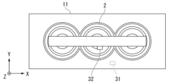
- FIG. 1B is a plan view of the transformer board 1 of the embodiment.
- the transformer board 1 includes a transformer 2, a housing 11, a first temperature detector 31, a second temperature detector 32, and a temperature determination section 5 (FIG. 2).
- the first temperature detector 31 , the second temperature detector 32 , and the temperature determination section 5 are an example of the overtemperature protection system 10 .
- the temperature determination unit 5 is an example of an overtemperature detection system 5A.
- the transformer 2 is, for example, a molded three-phase transformer.
- Transformer 2 is an example of a dry transformer.
- the transformer 2 is formed of a forced air cooling type cooled by a cooling device.
- the housing 11 is configured to accommodate the transformer 2 inside.
- the transformer 2 is installed inside the housing 11 .
- a cooling device used for cooling the transformer 2 is provided in the housing 11 .
- the cooling device may include an external air introduction type fan 11F that takes in room temperature air (CA) and discharges warm air HA.
- Fan 11F is an example of a cooling device provided in opening 11H of housing 11 .
- the opening 11H of the housing 11 is provided on the top surface of the housing 11, for example.
- An opening for taking in room temperature air (CA) may be provided in a door surface (not shown). It should be noted that providing a cooling device other than the fan 11F provided in the housing 11 is not limited, and it may be combined with the fan 11F as appropriate.
- the first temperature detector 31 detects the ambient temperature (first ambient temperature) of the housing 11 that has flowed into the housing 11 .
- the first temperature detector 31 is arranged, for example, inside the opening into which the outside air flows in the housing 11 and below the winding portion of the transformer 2 .
- the position shown in the figure is an example and is not limited to this.
- the second temperature detector 32 detects the ambient temperature of the transformer 2 (second ambient temperature).
- a second temperature sensor 32 is arranged near the transformer 2, for example above the V-phase winding of the transformer 2 having a UVW-phase winding. This position is easily affected by the temperature of the main body of the transformer 2 .
- the position shown in the figure is an example and is not limited to this.
- the transformer 2 placed inside the housing 11 of the transformer board 1 generates heat due to its own power loss. This heat is discharged outside the housing 11 by the operation of the fan 11F of the housing 11 . When the operation of the fan 11F of the housing 11 stops, the heat accumulated in the transformer 2 at that stage may increase the temperature around the transformer 2.
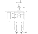
- FIG. 2 is a schematic configuration diagram around the transformer board 1 of the embodiment.
- An input-side circuit breaker CB is provided on the primary side of the transformer panel 1 .
- the input-side circuit breaker CB is in a conductive state and allows power from the power supply side to be supplied to the primary side of the transformer panel 1 . In the cutoff state, the supply of electric power from the power supply side to the primary side of the transformer panel 1 is cut off.
- the input side circuit breaker CB is an example of a switch arranged on the primary side of the transformer 2 .
- the input-side circuit breaker CB is formed, for example, so as to switch between a conductive state and a cut-off state by control.
- the secondary side of the transformer panel 1 is connected to loads such as a motor (M) and a cooling device (fan 11F) via load-side circuit breakers, disconnecting switches, and the like.
- loads such as a motor (M) and a cooling device (fan 11F) via load-side circuit breakers, disconnecting switches, and the like.
- the temperature determination unit 5 detects temperature anomalies in the transformer 2 .
- the temperature determination unit 5 is connected to a first temperature detector 31 and a second temperature detector 32 arranged inside the housing 11 . Further, the temperature determination unit 5 is supplied with a state signal of the input side circuit breaker CB so as to detect the live state of the primary side of the transformer 2 .
- the state signal of the input-side circuit breaker CB may be a signal indicating the call status of the load side of the input-side circuit breaker CB.
- the temperature determination unit 5 may output a control signal for controlling the state of the input side circuit breaker CB so as to cut off the power supply to the primary side of the transformer 2 .
- FIG. 3 is a configuration diagram of the temperature determination unit 5 of the embodiment.
- the temperature determination unit 5 includes filters 51 and 52, comparators 53 to 56, a filter 57, a gate 58, a one-shot gate 59, gates 61 to 66, and filters 67 and 68.
- the filters 51 and 52 are smoothing circuits. Filters 51 and 52 remove noise superimposed on their respective input signals.
- This smoothing circuit may be configured as a moving average circuit, or may be configured as a low-pass filter. These characteristics may be appropriately determined so that temperature changes are detected.
- the input of the filter 51 is connected to the output of the first temperature detector 31, and the signal TB indicating the detection result of the first temperature detector 31 is supplied.
- a filter 51 outputs a signal TBf obtained by converting the signal TB.
- the output of the second temperature sensor 32 is connected to the input of the filter 52, and a signal TV indicating the detection result of the second temperature sensor 32 is supplied.
- a filter 52 outputs a signal TVf obtained by converting the signal TV.
- the comparators 53 to 56 detect that the potential difference between the signal TBf and the signal TVf respectively supplied to the two inputs exceeds a predetermined value.
- the predetermined values set in the comparators 53 to 56 are different from each other. Assume that the comparators 53 to 56 are set to, for example, ⁇ T1, ⁇ T2, ⁇ T3, and ⁇ T4 in that order.
- Comparators 53 to 56 output the identified results as signal TAN, signal TFN, signal TAFS, and signal TFFS, respectively.
- a first input of gate 61 is connected to the output of comparator 53 .
- a first input of gate 62 is connected to the output of comparator 54 .
- the output of comparator 55 is connected to the first input of gate 63 .
- the output of comparator 56 is connected to the first input of gate 64 .
- Gates 61 to 64 are AND circuits. Note that the second inputs of gates 63 and 64 are negative logic. The inputs of gates 61 through 64 and gate 58, and their outputs, except the second inputs of gates 63 and 64, are all positive logic.
- the state signal CBCL1 of the input side circuit breaker CB is supplied to the terminal CBA.
- the state signal CBCL1 is in the logic state ST1 when the input side circuit breaker CB is closed and in the logic state ST0 when it is open.
- Terminal CBA is connected to the input of filter 57 .
- the filter 57 When the logic state ST1 of the input signal exceeds a predetermined time, the filter 57 outputs the logic state ST1 at a timing delayed by that time, and responds when the input signal changes to the logic state ST0. outputs the logic state ST0. Note that the filter 57 generates an output signal that holds the logic state of the input signal. For example, the filter 57 may generate a pulse in the logic state ST1 when the input signal continues for about 0.5 seconds after changing to the logic state ST1. Connected to the output of filter 57 are the second inputs of gates 61 through 64 and the second input of gate 58, respectively.
- a pair of gate 58 and one-shot gate 59 generates a mask signal that temporarily stops temperature abnormality detection.
- gate 58 is an AND circuit.
- the output of gate 58 is connected to the trigger input of one shot gate 59 .
- One-shot gate 59 outputs a negative pulse of a predetermined length upon detection of a trigger input at which the output signal of gate 58 changes from logic state ST0 to logic state ST1.
- one-shot gate 59 produces a pulse of logic state ST0, which in this case lasts 60 seconds.
- the output of one-shot gate 59 is connected to the third inputs of gates 61 and 62 .
- Gates 61 and 62 which are pulsed to logic state ST0, are deactivated during the pulse to logic state ST0, masking other input signals. In other words, the signals output from comparators 53 and 54 are masked by gates 61 and 62 while the logic state ST0 pulse is applied.
- the gate 65 is a positive logic input/positive logic output OR circuit.
- a first input of gate 65 is connected to the output of gate 61 and a second input is connected to the output of gate 63 .
- the output of gate 65 is connected to the input of filter 67 .
- the filter 67 When the logic state ST1 of the input signal exceeds a predetermined time, the filter 67 outputs the logic state ST1 at a timing delayed by that time, and responds when the input signal changes to the logic state ST0. outputs the logic state ST0. Note that the filter 67 generates an output signal that holds the logic state of the input signal. For example, the filter 67 may generate a pulse in the logic state ST1 when the logic state ST1 of the input signal continues for about one second.
- the output of filter 67 is connected to terminal OHA and to the first input of gate 58 .
- the gate 66 is a positive logic input/positive logic output OR circuit.
- a first input of gate 66 is connected to the output of gate 62 and a second input is connected to the output of gate 64 .
- the output of gate 66 is connected to the input of filter 68 .
- the filter 68 When the logic state ST1 of the input signal exceeds a predetermined time, the filter 68 outputs the logic state ST1 at a timing delayed by that time, and responds when the input signal changes to the logic state ST0. outputs the logic state ST0.
- the filter 67 may generate a pulse in the logic state ST1 when the logic state ST1 of the input signal continues for about one second. Note that the filter 68 generates an output signal that holds the logic state of the input signal.
- the output of filter 68 is connected to terminal OHF.
- the temperature determination unit 5 identifies the temperature difference (temperature difference) detected by the first temperature detector 31 and the second temperature detector 32 with the comparators 53 to 56, and detects temperature abnormality of the transformer 2. .
- the state in which 1 is output to the terminal OHA indicates that the temperature abnormality has reached the first stage
- the state in which 1 is output to the terminal OHF indicates the state that the temperature abnormality has reached the second stage.
- the first stage of the temperature abnormality is the stage of notifying an alarm indicating that the temperature abnormality has occurred
- the second stage of the temperature abnormality is the state in which the temperature abnormality has occurred and it is dangerous to continue the operation. It is time to notify.
- the state signal CBCL1 becomes the logic state ST0 when the input side circuit breaker CB is open, and the gates 63 and 64 are activated. Meanwhile, the outputs of gates 61 and 62 are deactivated, masking their input signals.
- the state signal CBCL1 becomes the logic state ST1
- the output state of the one-shot gate 59 activates the gates 61 and 62 .
- gates 63 and 64 are deactivated to mask the input signal.
- the identification results of the comparators 55 and 56 are valid, and when it is closed, the identification results of the comparators 53 and 54 are valid.
- thresholds ⁇ T1, ⁇ T2, ⁇ T3, and ⁇ T4 for detecting temperature differences set in the comparators 53 to 56 will be described.
- the thresholds ⁇ T2 and ⁇ T4 associated with the comparators 54 and 56 are set to a temperature difference that allows detection of the first stage of temperature abnormality.
- the threshold values ⁇ T1 and ⁇ T3 associated with the comparators 53 and 55 are set to a temperature difference that allows detection of the second stage of the temperature abnormality. For example, 120 degrees, 125 degrees, 130 degrees, and 135 degrees are set as the detection temperatures for the thresholds ⁇ T1, ⁇ T2, ⁇ T3, and ⁇ T4, respectively.
- a temperature lower than the above temperature for example, a temperature lower by 10 degrees
- a temperature lower by 10 degrees may be set.
- the comparators 53 and 54 detect the second stage and the first stage of the temperature abnormality, respectively.
- the threshold ⁇ T2 and the threshold ⁇ T2 are set so that the temperature difference is higher than the thresholds ⁇ T1 and ⁇ T3 so that the comparators 55 and 56 detect the second stage and the first stage of temperature abnormality, respectively.
- the first threshold temperature (threshold ⁇ T1) for determining the temperature of the transformer 2 while the cooling fan 11F is operating and A threshold temperature may be provided, including a second threshold temperature (threshold ⁇ T3) for determining the temperature of the transformer.
- the second threshold temperature (threshold ⁇ T3) should be lower than the threshold temperature (threshold ⁇ T2) in order to detect an event that stops the system from the temperature of the transformer 2 while the cooling fan 11F is operating.
- the above temperature is an example shown as a guideline, and may be determined as appropriate without being limited thereto.
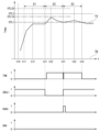
- FIG. 4 is a diagram for explaining the temperature of the transformer 2 during hot start of the embodiment.
- the graph of FIG. 4 shows the temperature difference between the temperatures detected by the first temperature detector 31 and the second temperature detector 32, and changes over time in the signals of each part.
- the graph shown at the top shows the temperature difference between the detected temperatures
- the solid line TV in the graph shows the temperature difference between the detected temperatures of the first temperature sensor 31 and the second temperature sensor 32 .
- the above temperature difference is simply referred to as "temperature of transformer 2”.
- the subsequent graphs show the signal TAN, the signal CBCL1, the signal OHAS, and the control signal SOHA, respectively.
- the signal TAN, the signal CBCL1, the signal OHAS, and the control signal SOHA take binary values of "0 (logical state ST0)" and "1 (logical state ST1)".
- the power supply from the transformer 2 to the load is stopped.
- the signal TAN, the signal OHAS, and the control signal SOHA are "0", and the signal CBCL1 is "1".
- state S1 When the temperature around the fan 11F exceeds the operation start temperature, the fan 11F starts operating due to temperature control of the fan 11F. If the temperature around the fan 11F exceeds the operation start temperature and the fan 11F is energized, the fan 11F will operate. As a result, cooling air starts to flow inside the housing 11 .
- the state at this stage is called a normal state (state S1).
- state S1 transformer 2 is supplying power to its load and fan 11F is operating.
- the state S1 when the amount of heat generated by the power loss of the transformer 2 and the cooling effect of the fan 11F are balanced, the temperature of the transformer 2 reaches thermal equilibrium (time t12). At this stage, the temperature of the transformer 2 detected by the second temperature sensor 32 is stable and almost constant.
- threshold temperatures OTL1 and OLT2 which are higher than the temperature at the time of thermal equilibrium, are set for detecting temperature anomalies.
- the threshold temperature OTL1 is set to a temperature that does not occur under normal conditions when the fan 11F is operating. Although this threshold temperature OTL1 is set higher than the temperature at normal thermal equilibrium, it is preferable to make the difference between the threshold temperature OTL1 and the temperature at thermal equilibrium relatively small. As a result, it is possible to increase the detection sensitivity when a temperature abnormality occurs.
- the threshold temperature OTL2 is set to a temperature that does not occur under normal operating conditions, regardless of whether the fan 11F is operating or not. This threshold temperature OTL2 is set higher than the threshold temperature OTL1, and is preferably a value that does not erroneously detect a temperature at which the risk of failure of the transformer 2 is low as a temperature abnormality.
- This state indicates a state in which power is no longer shared by the transformer 2 (referred to as state S2).
- state S2 a state in which power is no longer shared by the transformer 2
- power supply to the transformer 2 is stopped, and heat generation due to loss by the transformer 2 is stopped.
- heat accumulated in the transformer 2 until the power supply is stopped, and the temperature around the transformer 2 rises due to the dissipation of this heat.
- the temperature of the transformer 2 may become higher than the threshold temperature OTL1. Therefore, it is preferable to adjust the threshold temperature during the period of the state S2 and switch the threshold temperature so as not to detect the above temperature rise.
- a threshold temperature OTL1A and a threshold temperature OTL2A are set instead of the threshold temperature OTL1 and the threshold temperature OTL2.
- Threshold temperature OTL1A and threshold temperature OTL2A are set higher than threshold temperature OTL1 and threshold temperature OTL2, respectively.
- the state exceeding the threshold temperature OTL1A is not detected. More specifically, although the signal TAN is "1", the output of the gate 61 is "0" because the signal CBCL1 is “0". ” is retained.
- the temperature of transformer 2 begins to drop. This is because the heat accumulated in the transformer 2 is transmitted to the housing 11 by the dissipation of the heat accumulated in the transformer 2 and the natural convection in the housing 11, and the heat accumulated in the transformer 2 is transferred to the housing 11 from the surface of the housing 11 to the outside. By diverging.
- the temperature of the transformer 2 gradually decreases in this way, it is not suitable to restart the energization of the transformer 2 when the temperature of the transformer 2 is higher than the threshold temperature OTL1.
- the temperature determination unit 5 controls the input-side circuit breaker CB using the control signal SOHA output via the terminal OHA.
- the input side circuit breaker CB is energized according to this control, and the signal CBCL1 becomes "1".
- This state becomes a state in which power is supplied to the transformer 2 (state S3).
- the transformer 2 supplies power to the load again, so that the fan 11F is in operation.
- the situation inside the housing 11 differs between the time when the state S3 starts and the time when the state S1 ends.
- the temperature inside the housing 11 is different.
- the temperature inside the housing 11 at the start of the state S3 is higher than the temperature inside the housing 11 at the end of the state S1. Therefore, immediately after energization is resumed, the transformer 2 cannot be sufficiently cooled, and the temperature of the transformer 2 rises after time t31.
- the temperature rise of the transformer 2 that occurs after time t31 is detected by the comparator 53.
- the input-side circuit breaker CB is in an energized state, and the state signal CBCL1 is transitioning to "1".
- the output of one-shot gate 59 is at "1" at time t31. Therefore, the gate 61 is activated and the detection result by the comparator 53 is output from the gate 61 .
- the signal OHAS from the output of the gate 65 is output as a signal "1" indicating the abnormal temperature of the transformer 2 detected by the comparator 53 . This phenomenon is permissible in terms of design, and it is not appropriate to output the signal generated at this time as it is as a signal indicating an alarm (“1” of control signal SOHA).
- the gate 58 and the one-shot gate 59 respond to this. Then, the one-shot gate 59 outputs a pulse of "0" which continues for a predetermined time. This "0" pulse is supplied from the one-shot gate 59 to the gate 61 to deactivate the gate 61 so that the output of the gate 61 becomes “0". As a result, the gate 61 masks "the signal indicating the abnormal temperature of the transformer 2 detected by the comparator 53" and forms a pulse of "1” with a short duration. Accordingly, The signal OHAS output from the gate 65 is also a pulse of "1" with a short time width.
- the signal OHAS output by the gate 65 includes a relatively short pulse based on the "signal indicating the abnormal temperature of the transformer 2 detected by the comparator 53". Since the filter 67 in the subsequent stage limits this pulse, the control signal SOHA output from the filter 67 does not show a signal indicating abnormal temperature of the transformer 2 . As a result, the control signal SOHA output from the terminal OHA does not fluctuate, and the temperature of the transformer 2 at hot start can be stably detected.
- the time period during which the signal generated by the one-shot gate 59 masks "the signal indicating the abnormal temperature of the transformer 2 detected by the comparator 53" is set to a relatively short time, an important phenomenon that occurs during this period is does not omit the detection of For example, when an important phenomenon to be detected occurs, the "signal indicating the abnormal temperature of the transformer 2 detected by the comparator 53" continues longer than this masking time. Since such an important phenomenon to be detected can be detected without being masked, a signal indicating abnormality is outputted to the control signal SOHA of the terminal OHA accordingly.
- the overtemperature detection system 5A detects abnormal temperature of the transformer 2 (dry transformer) cooled by the fan 11F (cooling device).
- 5 A of over temperature detection systems are provided with the temperature determination part 5.
- FIG. The temperature determination unit 5 determines the temperature abnormality of the transformer 2 by changing the determination condition of the temperature abnormality of the transformer 2 depending on the operation state of the fan 11F being operated and stopped, thereby determining the transformer cooled by the fan 11F. Abnormal temperature of the vessel 2 can be detected.
- the overtemperature detection system 5 ⁇ /b>A may be used for protecting the transformer 2 by judging and outputting the abnormal temperature of the transformer 2 .
- the temperature determination unit 5 may limit the output of the temperature abnormality identification result until a predetermined condition is satisfied when the transformer 2 is hot started.
- the predetermined condition includes that the temperature of transformer 2 falls below the first threshold temperature if the temperature of transformer 2 was above the first threshold temperature at the time of hot start of transformer 2. It's okay to be
- the temperature determination unit 5 may detect a transition to a live line state on the primary side of the transformer 2 to identify a hot start of the transformer 2 .
- the temperature determination unit 5 can identify the hot start of the transformer 2 by detecting the state of the input-side circuit breaker CB arranged on the primary side of the transformer 2 .
- the temperature determination unit 5 detects that the temperature inside the housing 11 has risen to or above the threshold temperature OTL1, it does not necessarily determine that the temperature is abnormal.
- the temperature determination unit 5 does not handle an event in which a temperature exceeding the threshold temperature OTL1 is detected as a temperature abnormality that should stop the output of the transformer 2, but allows selection to continue the operation.
- the temperature determination unit 5 may continue the operation without determining that the temperature is abnormal during a predetermined period of time when power supply is restarted due to a hot start. During this period, the load may be operated with the same amount of power as in normal conditions without adjusting the power consumption of the load operation.
- FIG. 5 is a block diagram of the temperature determination section 5D of the second embodiment.
- the temperature determination unit 5D includes a processing circuit 100, for example.
- the CPU 101, storage unit 102, and driving unit 103 are connected by BUS.
- the processing circuit 100 is an example of the temperature determination section 5D.
- CPU 101 includes a processor that executes desired processing according to a software program.
- Storage unit 102 includes a semiconductor memory. Under the control of the CPU 101, the driving section 103 detects various signals and further generates a control signal for the input-side circuit breaker CB.
- the processing executed by the CPU 101 and the drive unit 103 will be collectively described simply as the processing of the temperature determination unit 5D.
- the temperature determination unit 5D is connected to the first temperature detector 31 and the second temperature detector 32 arranged inside the housing 11, like the temperature determination unit 5 described above. Further, the temperature determination unit 5D is supplied with a state signal of the input side circuit breaker CB so as to detect the live line state of the primary side of the transformer 2 .
- the state signal of the input-side circuit breaker CB may be a signal indicating the call status of the load side of the input-side circuit breaker CB.
- the temperature determination unit 5D may output a control signal for controlling the state of the input side circuit breaker CB so as to cut off the power supply to the primary side of the transformer 2.
- the processing performed by the CPU 101 and the drive unit 103 regarding this may be the same as the description of the operation of the first embodiment.
- the overtemperature detection system detects temperature anomalies in a dry transformer (hereinafter referred to as transformer) cooled by a cooling device.
- the over-temperature detection system includes a temperature determination section.
- the temperature judging section changes a judging condition for a temperature anomaly of the transformer according to an operating state of the cooling device being in operation and being stopped, and judging and outputting the temperature anomaly of the transformer. This allows the over-temperature detection system to detect temperature anomalies in the transformer cooled by the cooling device.
Landscapes
- Engineering & Computer Science (AREA)
- Power Engineering (AREA)
- Protection Of Transformers (AREA)
- Transformer Cooling (AREA)
- Housings And Mounting Of Transformers (AREA)
Abstract
Description
なお、以下の説明では、同一又は類似の機能を有する構成に同一の符号を付す。そして、それらの構成の重複する説明は省略する場合がある。なお、電気的に接続されることを、単に「接続される」ということがある。以下の説明に示す「電圧の測定値」とは、実際の電圧の測定値、実際の電圧の大きさを示す指標値、又は電圧の大きさを示す推定値のことである。以下の説明において、「乾式変圧器」のことを、単に「変圧器」として説明することがある。「変圧器の温度」として、「変圧器の周辺の空気の温度」のことを同義のものとして説明することがある。
変圧器盤1は、変圧器2と、筐体11と、第1温度検知器31と、第2温度検知器32と、温度判定部5(図2)を備える。第1温度検知器31と、第2温度検知器32と、温度判定部5は、過温度保護システム10の一例である。温度判定部5は、過温度検出システム5Aの一例である。
変圧器盤1の1次側には、入力側遮断機CBが設けられている。入力側遮断機CBは、導通状態で、電源側からの電力を変圧器盤1の1次側に供給可能にする。遮断状態で、電源側からの電力の変圧器盤1の1次側への供給を遮断する。入力側遮断機CBは、変圧器2の1次側に配置されたスイッチの一例である。入力側遮断機CBは、例えば、制御により導通状態と遮断状態が切り替わるように形成されている。
温度判定部5は、フィルタ51と52と、コンパレータ53から56と、フィルタ57と、ゲート58と、ワンショットゲート59と、ゲート61から66と、フィルタ67と68とを備える。
コンパレータ53の出力には、ゲート61の第1入力が接続されている。
コンパレータ54の出力には、ゲート62の第1入力が接続されている。
コンパレータ55の出力には、ゲート63の第1入力が接続されている。
コンパレータ56の出力には、ゲート64の第1入力が接続されている。
温度判定部5は、第1温度検知器31と第2温度検知器32が夫々検出した温度の差(温度差)を、コンパレータ53から56によって識別して、変圧器2の温度異常を検出する。端子OHAに1が出力される状態は、温度異常の第1段階に達した状態であることを示し、端子OHFに1が出力される状態は、温度異常の第2段階に達した状態であることを示す。温度異常の第1段階が、温度異常が発生したことを示すアラームを通知する段階であり、温度異常の第2段階が、温度異常が発生していて、動作を継続させることが危険な状態を通知する段階である。
図4は、実施形態のホットスタート時に係る変圧器2の温度について説明するための図である。図4のグラフに、第1温度検知器31と第2温度検知器32の検出温度の温度差と、各部の信号の経時変化を示す。最上段に示すグラフは、検出温度の温度差を示し、グラフ中の実線TVは、第1温度検知器31と第2温度検知器32の検出温度の温度差を示す。以下の説明では、上記の温度差のことを、単に「変圧器2の温度」と呼ぶ。次段以降のグラフは、信号TAN、信号CBCL1、信号OHAS、及び制御信号SOHAを夫々示す。信号TAN、信号CBCL1、信号OHAS、及び制御信号SOHAは、「0(論理状態ST0)」と「1(論理状態ST1)」の2値をとる。
例えば、状態S3の開始時点と、状態S1の終了時点の負荷の消費電力が同じであるとすれば、変圧器2の電力損失も、状態S3の開始時点と、状態S1の終了時点で同じになる。この状況であれば、変圧器2の発熱量も同等になる。
ゲート65が出力する信号OHASも、上記の時間幅の短い「1」のパルスになる。
変形例について説明する。実施形態では、第1温度検知器31と第2温度検知器32との2つの温度検知器の検出結果に基づいた温度差を判定に利用する事例について説明した。これに変えて、第2温度検知器32のみを利用して、第2温度検知器32が検出した温度を判定に利用してもよい。
第2の実施形態について説明する。
本実施形態は、同様の機能をデジタル処理で実現する温度判定部5Dについて説明する。図5は、第2の実施形態の温度判定部5Dのブロック図である。温度判定部5Dは、例えば処理回路100を備える。図5に示す処理回路100は、CPU101と、記憶部102と、駆動部103とを備える。CPU101と、記憶部102と、駆動部103は、BUSで接続されている。処理回路100は、温度判定部5Dの一例である。CPU101は、ソフトウェアプログラムに従い、所望の処理を実行するプロセッサを含む。記憶部102は、半導体メモリを含む。駆動部103は、CPU101の制御に従い、各種信号を検出し、さらに入力側遮断機CBの制御信号を生成する。
Claims (9)
- 冷却装置によって冷却される乾式変圧器(以下、変圧器という。)の温度異常を検出する過温度検出システムであって、
前記冷却装置の動作中と停止中の動作状態により前記変圧器の温度異常の判定条件を代えて、前記変圧器の温度異常を判定して出力する温度判定部
を備える過温度検出システム。 - 前記冷却装置は、冷却用のファンを含み、
前記変圧器は、前記冷却用のファンが設けられた筐体の内部に設置されている、
請求項1に記載の過温度検出システム。 - 前記変圧器の温度異常の判定条件として、前記冷却用のファンの動作中に前記変圧器の温度を判定するための第1閾値温度と、前記冷却用のファンの停止中に前記変圧器の温度を判定するための第2閾値温度とを含む閾値温度を設ける、
請求項2に記載の過温度検出システム。 - 前記温度判定部は、
前記変圧器のホットスタート時に所定の条件が満たされるまで温度異常の識別結果の出力を制限する、
請求項2に記載の過温度検出システム。 - 前記所定の条件には、前記変圧器のホットスタート時に、前記変圧器の温度が前記変圧器の温度が前記変圧器の温度を判定するための第1閾値温度を超えていたならば、前記第1閾値温度よりも下がることが含まれる、
請求項4に記載の過温度検出システム。 - 前記温度判定部は、
前記変圧器の一次側の活線状態への遷移を検出することで、前記変圧器のホットスタート時を識別する
請求項2に記載の過温度検出システム。 - 前記温度判定部は、
前記変圧器の一次側に配置された入力側遮断機の状態を検出することで、前記変圧器のホットスタート時を識別する
請求項2に記載の過温度検出システム。 - 請求項1から請求項7の何れか1項の過温度検出システムと、
検出された前記変圧器の温度異常に応じて前記変圧器の1次側に配置されたスイッチを開放させる駆動部と
を備える過温度保護システム。 - 冷却装置によって冷却される乾式変圧器(以下、変圧器という。)の温度異常を検出する過温度検出方法であって、
前記冷却装置の動作中と停止中の動作状態により前記変圧器の温度異常の判定条件を代えて、前記変圧器の温度異常を温度判定部が判定して出力するステップ
を含む過温度検出方法。
Priority Applications (4)
| Application Number | Priority Date | Filing Date | Title |
|---|---|---|---|
| JP2022567216A JP7462796B2 (ja) | 2021-09-03 | 2021-09-03 | 過温度検出システム、過温度保護システム及び過温度検出方法 |
| US18/263,175 US20240087790A1 (en) | 2021-09-03 | 2021-09-03 | Overtemperature detecting system, overtemperature protecting system, and overtemperature detecting method |
| CN202180059724.1A CN116261759A (zh) | 2021-09-03 | 2021-09-03 | 过温检测系统、过温保护系统以及过温检测方法 |
| PCT/JP2021/032396 WO2023032142A1 (ja) | 2021-09-03 | 2021-09-03 | 過温度検出システム、過温度保護システム及び過温度検出方法 |
Applications Claiming Priority (1)
| Application Number | Priority Date | Filing Date | Title |
|---|---|---|---|
| PCT/JP2021/032396 WO2023032142A1 (ja) | 2021-09-03 | 2021-09-03 | 過温度検出システム、過温度保護システム及び過温度検出方法 |
Publications (1)
| Publication Number | Publication Date |
|---|---|
| WO2023032142A1 true WO2023032142A1 (ja) | 2023-03-09 |
Family
ID=85412438
Family Applications (1)
| Application Number | Title | Priority Date | Filing Date |
|---|---|---|---|
| PCT/JP2021/032396 Ceased WO2023032142A1 (ja) | 2021-09-03 | 2021-09-03 | 過温度検出システム、過温度保護システム及び過温度検出方法 |
Country Status (4)
| Country | Link |
|---|---|
| US (1) | US20240087790A1 (ja) |
| JP (1) | JP7462796B2 (ja) |
| CN (1) | CN116261759A (ja) |
| WO (1) | WO2023032142A1 (ja) |
Citations (3)
| Publication number | Priority date | Publication date | Assignee | Title |
|---|---|---|---|---|
| JPS5840413B2 (ja) * | 1975-03-24 | 1983-09-06 | 株式会社日立製作所 | カンシキセイシユウドウキノ ホゴホウシキ |
| JPS58193731U (ja) * | 1982-06-10 | 1983-12-23 | 三菱電機株式会社 | ガス絶縁電気装置 |
| JPS60160031U (ja) * | 1984-03-29 | 1985-10-24 | 株式会社島津製作所 | 電源保護回路 |
Family Cites Families (2)
| Publication number | Priority date | Publication date | Assignee | Title |
|---|---|---|---|---|
| JPH02231919A (ja) * | 1989-03-03 | 1990-09-13 | Hitachi Ltd | 電力機器の過熱保護装置 |
| WO2020241659A1 (ja) | 2019-05-28 | 2020-12-03 | 住友重機械工業株式会社 | コンバータ装置、産業機械 |
-
2021
- 2021-09-03 JP JP2022567216A patent/JP7462796B2/ja active Active
- 2021-09-03 CN CN202180059724.1A patent/CN116261759A/zh active Pending
- 2021-09-03 WO PCT/JP2021/032396 patent/WO2023032142A1/ja not_active Ceased
- 2021-09-03 US US18/263,175 patent/US20240087790A1/en active Pending
Patent Citations (3)
| Publication number | Priority date | Publication date | Assignee | Title |
|---|---|---|---|---|
| JPS5840413B2 (ja) * | 1975-03-24 | 1983-09-06 | 株式会社日立製作所 | カンシキセイシユウドウキノ ホゴホウシキ |
| JPS58193731U (ja) * | 1982-06-10 | 1983-12-23 | 三菱電機株式会社 | ガス絶縁電気装置 |
| JPS60160031U (ja) * | 1984-03-29 | 1985-10-24 | 株式会社島津製作所 | 電源保護回路 |
Also Published As
| Publication number | Publication date |
|---|---|
| US20240087790A1 (en) | 2024-03-14 |
| JP7462796B2 (ja) | 2024-04-05 |
| CN116261759A (zh) | 2023-06-13 |
| JPWO2023032142A1 (ja) | 2023-03-09 |
Similar Documents
| Publication | Publication Date | Title |
|---|---|---|
| US9042069B2 (en) | Power supply controller | |
| KR101639488B1 (ko) | 암 쇼트 방지를 위한 게이트 구동 회로 및 방법 | |
| US11349472B2 (en) | Method for reducing a thermal load on a controllable switching element | |
| CN104332954B (zh) | 用于对电机进行热保护及功率调节的电路 | |
| JP4154639B2 (ja) | モータスタータの温度保護制御方法及び装置 | |
| US20160003688A1 (en) | Arrangement for testing a device for protecting an electronic component against overheating and pertaining method | |
| US8751175B2 (en) | Method and device for overload detection in battery-operated devices having an electric motor | |
| US10424914B2 (en) | Overtemperature protection | |
| CN100541955C (zh) | 具有过载保护的电源装置 | |
| EP3650348B1 (en) | Method for managing over-temperature excursions in a failed-fixed control system | |
| CN104247188A (zh) | 通电电路的保护装置 | |
| WO2023032142A1 (ja) | 過温度検出システム、過温度保護システム及び過温度検出方法 | |
| US11146221B2 (en) | Method for overtemperature protection and audio apparatus | |
| US10072666B2 (en) | Hermetic compressor driving device | |
| JP3818082B2 (ja) | インバータ | |
| JP5802151B2 (ja) | 電気デバイスの電源電圧回路用の温度保護回路 | |
| US11581727B2 (en) | Assembly for monitoring a winding threshold temperature | |
| WO2021069315A1 (en) | Motor protection device | |
| JP5157091B2 (ja) | 半導体保護回路装置 | |
| JP2007323991A (ja) | 漏電遮断器 | |
| TWM674823U (zh) | 馬達過電流保護裝置 | |
| WO2017094151A1 (ja) | 空気調和機の保護回路および保護方法 | |
| JPH07264770A (ja) | 電源機器の保護回路 | |
| JPH03165274A (ja) | 半導体素子の温度試験装置 |
Legal Events
| Date | Code | Title | Description |
|---|---|---|---|
| ENP | Entry into the national phase |
Ref document number: 2022567216 Country of ref document: JP Kind code of ref document: A |
|
| 121 | Ep: the epo has been informed by wipo that ep was designated in this application |
Ref document number: 21955293 Country of ref document: EP Kind code of ref document: A1 |
|
| WWE | Wipo information: entry into national phase |
Ref document number: 202317050512 Country of ref document: IN |
|
| WWE | Wipo information: entry into national phase |
Ref document number: 18263175 Country of ref document: US |
|
| NENP | Non-entry into the national phase |
Ref country code: DE |
|
| 122 | Ep: pct application non-entry in european phase |
Ref document number: 21955293 Country of ref document: EP Kind code of ref document: A1 |