WO2023032137A1 - データ変更方法、データ再生方法、プログラムおよびデータ変更装置 - Google Patents
データ変更方法、データ再生方法、プログラムおよびデータ変更装置 Download PDFInfo
- Publication number
- WO2023032137A1 WO2023032137A1 PCT/JP2021/032374 JP2021032374W WO2023032137A1 WO 2023032137 A1 WO2023032137 A1 WO 2023032137A1 JP 2021032374 W JP2021032374 W JP 2021032374W WO 2023032137 A1 WO2023032137 A1 WO 2023032137A1
- Authority
- WO
- WIPO (PCT)
- Prior art keywords
- data
- control data
- pronunciation
- timing information
- beat
- Prior art date
- Legal status (The legal status is an assumption and is not a legal conclusion. Google has not performed a legal analysis and makes no representation as to the accuracy of the status listed.)
- Ceased
Links
Images







Classifications
-
- G—PHYSICS
- G11—INFORMATION STORAGE
- G11B—INFORMATION STORAGE BASED ON RELATIVE MOVEMENT BETWEEN RECORD CARRIER AND TRANSDUCER
- G11B27/00—Editing; Indexing; Addressing; Timing or synchronising; Monitoring; Measuring tape travel
- G11B27/02—Editing, e.g. varying the order of information signals recorded on, or reproduced from, record carriers
- G11B27/031—Electronic editing of digitised analogue information signals, e.g. audio or video signals
-
- G—PHYSICS
- G06—COMPUTING OR CALCULATING; COUNTING
- G06F—ELECTRIC DIGITAL DATA PROCESSING
- G06F3/00—Input arrangements for transferring data to be processed into a form capable of being handled by the computer; Output arrangements for transferring data from processing unit to output unit, e.g. interface arrangements
- G06F3/01—Input arrangements or combined input and output arrangements for interaction between user and computer
- G06F3/048—Interaction techniques based on graphical user interfaces [GUI]
- G06F3/0484—Interaction techniques based on graphical user interfaces [GUI] for the control of specific functions or operations, e.g. selecting or manipulating an object, an image or a displayed text element, setting a parameter value or selecting a range
- G06F3/04842—Selection of displayed objects or displayed text elements
-
- G—PHYSICS
- G06—COMPUTING OR CALCULATING; COUNTING
- G06F—ELECTRIC DIGITAL DATA PROCESSING
- G06F3/00—Input arrangements for transferring data to be processed into a form capable of being handled by the computer; Output arrangements for transferring data from processing unit to output unit, e.g. interface arrangements
- G06F3/01—Input arrangements or combined input and output arrangements for interaction between user and computer
- G06F3/048—Interaction techniques based on graphical user interfaces [GUI]
- G06F3/0484—Interaction techniques based on graphical user interfaces [GUI] for the control of specific functions or operations, e.g. selecting or manipulating an object, an image or a displayed text element, setting a parameter value or selecting a range
- G06F3/04847—Interaction techniques to control parameter settings, e.g. interaction with sliders or dials
-
- G—PHYSICS
- G06—COMPUTING OR CALCULATING; COUNTING
- G06F—ELECTRIC DIGITAL DATA PROCESSING
- G06F3/00—Input arrangements for transferring data to be processed into a form capable of being handled by the computer; Output arrangements for transferring data from processing unit to output unit, e.g. interface arrangements
- G06F3/16—Sound input; Sound output
- G06F3/167—Audio in a user interface, e.g. using voice commands for navigating, audio feedback
-
- G—PHYSICS
- G10—MUSICAL INSTRUMENTS; ACOUSTICS
- G10G—REPRESENTATION OF MUSIC; RECORDING MUSIC IN NOTATION FORM; ACCESSORIES FOR MUSIC OR MUSICAL INSTRUMENTS NOT OTHERWISE PROVIDED FOR, e.g. SUPPORTS
- G10G3/00—Recording music in notation form, e.g. recording the mechanical operation of a musical instrument
- G10G3/04—Recording music in notation form, e.g. recording the mechanical operation of a musical instrument using electrical means
-
- G—PHYSICS
- G10—MUSICAL INSTRUMENTS; ACOUSTICS
- G10H—ELECTROPHONIC MUSICAL INSTRUMENTS; INSTRUMENTS IN WHICH THE TONES ARE GENERATED BY ELECTROMECHANICAL MEANS OR ELECTRONIC GENERATORS, OR IN WHICH THE TONES ARE SYNTHESISED FROM A DATA STORE
- G10H1/00—Details of electrophonic musical instruments
-
- G—PHYSICS
- G10—MUSICAL INSTRUMENTS; ACOUSTICS
- G10H—ELECTROPHONIC MUSICAL INSTRUMENTS; INSTRUMENTS IN WHICH THE TONES ARE GENERATED BY ELECTROMECHANICAL MEANS OR ELECTRONIC GENERATORS, OR IN WHICH THE TONES ARE SYNTHESISED FROM A DATA STORE
- G10H1/00—Details of electrophonic musical instruments
- G10H1/0008—Associated control or indicating means
-
- G—PHYSICS
- G10—MUSICAL INSTRUMENTS; ACOUSTICS
- G10H—ELECTROPHONIC MUSICAL INSTRUMENTS; INSTRUMENTS IN WHICH THE TONES ARE GENERATED BY ELECTROMECHANICAL MEANS OR ELECTRONIC GENERATORS, OR IN WHICH THE TONES ARE SYNTHESISED FROM A DATA STORE
- G10H1/00—Details of electrophonic musical instruments
- G10H1/36—Accompaniment arrangements
- G10H1/40—Rhythm
-
- G—PHYSICS
- G10—MUSICAL INSTRUMENTS; ACOUSTICS
- G10H—ELECTROPHONIC MUSICAL INSTRUMENTS; INSTRUMENTS IN WHICH THE TONES ARE GENERATED BY ELECTROMECHANICAL MEANS OR ELECTRONIC GENERATORS, OR IN WHICH THE TONES ARE SYNTHESISED FROM A DATA STORE
- G10H1/00—Details of electrophonic musical instruments
- G10H1/36—Accompaniment arrangements
- G10H1/40—Rhythm
- G10H1/42—Rhythm comprising tone forming circuits
-
- G—PHYSICS
- G11—INFORMATION STORAGE
- G11B—INFORMATION STORAGE BASED ON RELATIVE MOVEMENT BETWEEN RECORD CARRIER AND TRANSDUCER
- G11B27/00—Editing; Indexing; Addressing; Timing or synchronising; Monitoring; Measuring tape travel
- G11B27/005—Reproducing at a different information rate from the information rate of recording
-
- G—PHYSICS
- G11—INFORMATION STORAGE
- G11B—INFORMATION STORAGE BASED ON RELATIVE MOVEMENT BETWEEN RECORD CARRIER AND TRANSDUCER
- G11B27/00—Editing; Indexing; Addressing; Timing or synchronising; Monitoring; Measuring tape travel
- G11B27/10—Indexing; Addressing; Timing or synchronising; Measuring tape travel
-
- G—PHYSICS
- G10—MUSICAL INSTRUMENTS; ACOUSTICS
- G10H—ELECTROPHONIC MUSICAL INSTRUMENTS; INSTRUMENTS IN WHICH THE TONES ARE GENERATED BY ELECTROMECHANICAL MEANS OR ELECTRONIC GENERATORS, OR IN WHICH THE TONES ARE SYNTHESISED FROM A DATA STORE
- G10H2210/00—Aspects or methods of musical processing having intrinsic musical character, i.e. involving musical theory or musical parameters or relying on musical knowledge, as applied in electrophonic musical tools or instruments
- G10H2210/375—Tempo or beat alterations; Music timing control
- G10H2210/381—Manual tempo setting or adjustment
-
- G—PHYSICS
- G10—MUSICAL INSTRUMENTS; ACOUSTICS
- G10H—ELECTROPHONIC MUSICAL INSTRUMENTS; INSTRUMENTS IN WHICH THE TONES ARE GENERATED BY ELECTROMECHANICAL MEANS OR ELECTRONIC GENERATORS, OR IN WHICH THE TONES ARE SYNTHESISED FROM A DATA STORE
- G10H2220/00—Input/output interfacing specifically adapted for electrophonic musical tools or instruments
- G10H2220/091—Graphical user interface [GUI] specifically adapted for electrophonic musical instruments, e.g. interactive musical displays, musical instrument icons or menus; Details of user interactions therewith
- G10H2220/101—Graphical user interface [GUI] specifically adapted for electrophonic musical instruments, e.g. interactive musical displays, musical instrument icons or menus; Details of user interactions therewith for graphical creation, edition or control of musical data or parameters
- G10H2220/116—Graphical user interface [GUI] specifically adapted for electrophonic musical instruments, e.g. interactive musical displays, musical instrument icons or menus; Details of user interactions therewith for graphical creation, edition or control of musical data or parameters for graphical editing of sound parameters or waveforms, e.g. by graphical interactive control of timbre, partials or envelope
Definitions
- the present disclosure relates to a method of changing data for controlling pronunciation.
- the sound generation control data defines the speed (tempo) of automatic performance. That is, when the sound generation control data is reproduced, the performance sound recorded in the sound generation control data is reproduced.
- the tempo control by the user is realized, for example, by swinging the portable device held in the user's hand like a baton. Therefore, the performance sound recorded in the sound generation control data is not reproduced as it is, but the performance sound is reproduced with the reproduction speed changed according to the user's operation.
- a selection for selecting a modification method to be applied to pronunciation control data defining pronunciation timing information from a plurality of modification methods including a first modification method and a second modification method providing a user interface, correcting the timing information when applying the first change method is selected, and correcting the timing information for a predetermined data section according to the correction amount of the timing information in the data section.
- modifying the pronunciation control data by adding information to correct the timing information based on beat positions according to a predetermined tempo when applying the second modification method is selected; provides a data modification method comprising: modifying the pronunciation control data.
- FIG. 1 is a diagram showing the hardware configuration of a mobile device and an electronic musical instrument according to one embodiment
- FIG. 6 is a flow chart showing processing in a print mode in one embodiment.
- FIG. 10 is a diagram showing an example of a recording user interface (before an instruction to start recording);
- FIG. 10 is a diagram showing an example of a recording user interface (after instructing to start recording);
- FIG. 10 illustrates an example of a selection user interface;
- 4 is a flow chart showing processing in a print mode (the part following FIG. 3) in one embodiment.
- 4 is a flow chart showing AI quantization processing in one embodiment.
- FIG. 10 is a diagram showing an example of a beat correction user interface (before instruction for correction).
- FIG. 10 is a diagram showing an example of a beat correction user interface (before instruction for correction).
- FIG. 4 is a diagram for explaining an example of sound generation control data;
- FIG. 4 is a flow chart showing data correction processing in one embodiment.
- FIG. 10 is a diagram for explaining an example of correcting timing information;
- FIG. 10 is a diagram for explaining a comparison of sound generation control data before and after change;
- 4 is a flowchart illustrating MIDI quantization processing in one embodiment.
- FIG. 10 is a diagram showing an example of a quantize setting user interface; 4 is a flow chart showing delay offset processing in one embodiment.
- FIG. 10 is a diagram showing an example of an offset setting user interface;
- FIG. 10 is a diagram for comparing and explaining sound generation control data before and after a delay offset;
- FIG. 10 is a diagram for comparing and explaining sound generation control data before and after a delay offset;
- 4 is a flowchart showing data reproduction processing in one embodiment.
- FIG. 10 is
- the portable device 10 can record a performance on the electronic musical instrument 80 and reproduce the recorded performance on the electronic musical instrument 80 . In this reproduction, it is possible to select either to reproduce the recorded performance as it is or to reproduce at a speed according to the user's motion (for example, the motion of swinging the portable device 10 like a baton). .
- the portable device 10 can generate data corresponding to the recorded performance and modify the data so that it can be used in any of the above reproductions. Specific processing for realizing each of these functions will be described later.
- FIG. 2 is a diagram showing the hardware configuration of the portable device and the electronic musical instrument according to one embodiment.
- Portable device 10 includes control unit 110 , storage unit 120 , display unit 130 , operation unit 140 , sensor unit 150 , speaker 170 , communication unit 180 and interface 190 .
- the mobile device 10 is not limited to including all of these components, and may include other components such as a camera and a position detection unit.
- the control unit 110 is an example of a computer including a processor such as a CPU (Central Processing Unit) and a storage device such as a RAM.
- the control unit 110 executes a program 121 stored in the storage unit 120 using a CPU (processor), and causes the portable device 10 to implement functions for executing various processes described later.
- a processor such as a CPU (Central Processing Unit)
- a storage device such as a RAM.
- the control unit 110 executes a program 121 stored in the storage unit 120 using a CPU (processor), and causes the portable device 10 to implement functions for executing various processes described later.
- the data stored in the storage unit 120 includes performance record data 123, for example.
- the performance recording data 123 includes various data related to the performance, such as metadata such as the name of the music played and data related to the sound of the performance.
- the data on the performance sound includes sound generation control data 125 that defines the timing information of the sound generated by the performance.
- the sound generation control data 125 is data described in a predetermined format, for example, data described in MIDI format.
- the pronunciation timing information is information indicating the timing at which the sound is generated, and is indicated by information such as note-on, note-off, delta time, and tempo, for example.
- the sound control data 125 also includes other information corresponding to sound, such as pitch (note number).
- the display unit 130 is a display having a display area for displaying various screens under the control of the control unit 110.
- the displayed screen includes a plurality of user interfaces, which will be described later.
- the operation unit 140 is an operation device that outputs a signal to the control unit 110 according to a user's operation.
- operation unit 140 is a touch sensor arranged on the surface of display unit 130 . Therefore, the display unit 130 and the operation unit 140 are used as a touch panel by mutual functions.
- the operation unit 140 may include switches and the like arranged on the housing of the mobile device 10 .
- the sensor unit 150 outputs a signal corresponding to the movement of the mobile device 10 to the control unit 110 .
- the sensor unit 150 includes, for example, an acceleration sensor, a gyro sensor, etc., and measures the movement of the mobile device 10 .
- the speaker 170 generates sound by amplifying and outputting the sound waveform signal supplied from the control unit 110 .
- the communication unit 180 is a wireless communication module for connecting to the network NW under the control of the control unit 110 and communicating with other devices such as the data management server 90 connected to the network NW.
- the interface 190 includes a communication module for communicating with other devices such as the electronic musical instrument 80 by infrared communication or short-range wireless communication.
- the interface 190 is used for communication without going through the network NW.
- Interface 190 may include modules that provide wired rather than wireless communication.
- Electronic musical instrument 80 is an electronic keyboard device such as an electronic piano, and includes performance operators 810 , tone generator section 830 , speaker 870 and interface 890 , as described above.
- the performance operator 810 includes a plurality of keys, and outputs a signal to the tone generator section 830 according to the operation of each key.
- Interface 890 includes a communication module for communicating wirelessly or by wire with external devices. In this example, the interface 890 connects with the interface 190 of the portable device 10 by short-range wireless communication to transmit and receive data in a predetermined format (MIDI format in this example).
- the sound source unit 830 includes a DSP (Digital Signal Processor) and generates a sound waveform signal according to the pronunciation instruction signal.
- the sounding instruction signal corresponds to the signal output from performance operator 810 and the data transmitted from portable device 10 via interface 890 .
- the tone generator section 830 converts the sound generation instruction signal corresponding to the signal output from the performance operator 810 into data in MIDI format and outputs the data to the interface 890 .
- the electronic musical instrument 80 can transmit data corresponding to the operation of the performance operator 810 (hereinafter sometimes referred to as performance information) to the portable device 10 .
- FIG. 3 is a flow chart showing processing in a recording mode in one embodiment.
- FIG. 4 is a diagram showing an example of the recording user interface (before instructing to start recording).
- FIG. 5 is a diagram showing an example of the recording user interface (after instructing recording).
- the control unit 110 provides the user with a recording user interface (recording UI) by displaying a screen described below on the display unit 130 (step S101).
- the recording user interface (hereinafter sometimes referred to as interface RD) shown in FIG. 4 is a display example before the start of performance recording is instructed.
- the interface RD includes an area TS for setting the recording tempo (hereinafter sometimes referred to as recording tempo), an area RT for displaying the recording time, and a record button RB for instructing start and end of recording. .
- the control unit 110 waits until an instruction to start recording the performance is input (step S103; No).
- an instruction to start recording is input to the portable device 10 by operating the record button RB shown in FIG. 4 (step S103; Yes)
- the control unit 110 displays the record button RB as shown in FIG.
- beats are provided to the user (step S105).
- Providing beats is realized by, for example, generating a metronome sound from the portable device 10 .
- a metronome sound is generated corresponding to each beat specified at intervals determined by the recording tempo. For example, if the recording tempo is 120, a metronome sound will be generated with a beat length of 500 milliseconds.
- the mobile device 10 may provide beats to the user not only by sound but also by light, vibration, or the like.
- the control unit 110 records the sound generation control data 125 in the storage unit 120 based on the performance information provided from the electronic musical instrument 80 (step S107) until an instruction to end recording is input (step S109; No). At this time, beats are still provided to the user.
- the control section 110 ends the beat provision (step S111). Subsequently, the control unit 110 provides a selection user interface (selection UI) by displaying a screen described below on the display unit 130 (step S113).
- the control unit 110 may terminate once the recording of the sound generation control data 125 is completed according to the user's instruction.
- the control unit 110 may provide a selection user interface according to a user's instruction, and may further provide a user interface for designating the pronunciation control data 125 to be processed. Data other than the sound generation control data 125 recorded in the recording mode may be specified as the object of processing.
- the interface SD includes change selection buttons AB, MB, DB corresponding to each change method.
- AI quantize detects the beat position from the pronunciation control data 125, and corrects the timing information according to the relationship between the beat position specified from the original pronunciation control data 125 and the detected beat position. This is the process of changing the control data 125 .
- AI Artificial Intelligence
- MIDI quantize is a process of changing the sound generation control data 125 so as to correct the timing information according to the specified resolution.
- “Delay offset” is processing for changing the sound generation control data 125 so as to offset timing information corresponding to a plurality of sounds.
- the interface SD includes a save button B1 for saving the sound control data 125, a delete button B2 for discarding the sound control data 125, and a play button PB for playing back the sound control data 125.
- the play button PB When the play button PB is operated, the sound control data 125 is read and the sound indicated by the sound control data 125 is reproduced. This sound may be generated by the portable device 10 or may be generated by the electronic musical instrument 80 .
- the portable device 10 may transmit a sound generation instruction signal to the electronic musical instrument 80 .
- a playback position is indicated by a playback marker PM. The user can change the playback position in the sound generation control data 125 by changing the position of the playback marker PM.
- FIG. 7 is a flow chart showing processing in the recording mode (the part following FIG. 3) in one embodiment.
- Control unit 110 waits for an instruction input from the user to interface SD (step S201; No, S203; No, S205; No, S207; No, S209; No).
- a state in which the control unit 110 waits for an instruction in this manner is referred to as an instruction standby state.
- step S201 When an AI quantize instruction is input by operating the change selection button AB (step S201; Yes), the control unit 110 executes the AI quantize process (step S300) and returns to the instruction standby state. AI quantize processing will be described later.
- step S203 When a MIDI quantization instruction is input by operating the change selection button MB (step S203; Yes), the control unit 110 executes the MIDI quantization process (step S400) and returns to the instruction waiting state. MIDI quantize processing will be described later.
- step S205 When the change selection button DB is operated to input a delay offset instruction (step S205; Yes), the control unit 110 executes the delay offset process (step S500) and returns to the instruction waiting state.
- the delay offset processing will be described later.
- step S207 When the save button B1 is operated to input a data save instruction (step S207; Yes), the control unit 110 saves the sound generation control data 125 (step S211), and ends the recording mode processing. .
- the delete button B2 is operated to input an instruction to discard the data (step S209; Yes)
- the control unit 110 discards the sound generation control data 125 (step S213) and terminates the recording mode processing. .
- FIG. 8 is a flowchart showing AI quantization processing in one embodiment.
- the control unit 110 converts the sound generation control data 125 into audio data (step S301).
- the audio data is data in which the sounding according to the timing information defined in the sounding control data 125 is indicated by a sound waveform signal. This sound waveform signal may be generated by the portable device 10 or may be generated by the electronic musical instrument 80 and received by the portable device 10 .
- Control unit 110 detects beats based on the audio data (step S303).
- Beats can be detected based on changes in the amplitude of the sound waveform signal.
- AI technology is used for beat detection.
- beat positions can be obtained from the trained model.
- a specific method for detecting beats is not limited to the case of using AI technology, and known beat detection methods can be applied.
- Beat detection is not limited to audio data, and may be performed on the pronunciation control data 125 .
- the control unit 110 provides a beat correction interface (beat correction UI: first user interface) by displaying a screen described below on the display unit 130 (step S305).
- the control unit 110 waits until an instruction to correct the beat position or an instruction to perform data correction processing is input to the beat correction interface (step S311; No, S321; No).
- the control section 110 corrects the beat position (step S313) and waits again (step S311; No, S321; No).
- the control unit 110 executes the data correction process (step S330) and ends the AI quantize process.
- Data correction processing may be instructed without inputting an instruction to correct the beat position. In this case, data correction processing is executed using the detected beat position as it is.
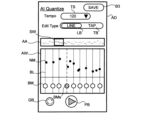
- FIG. 9 is a diagram showing an example of the beat correction user interface (before the correction instruction).
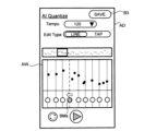
- FIG. 10 is a diagram showing an example of the beat correction user interface (before instructing correction).
- a beat correction interface (hereinafter sometimes referred to as an interface AD) includes an area TS for setting an average tempo, a line button LB and a tap button TB for setting a beat position editing method, a play button PB, and a redetection button. QB, and save button B3.
- the tempo (recording tempo) when the sound generation control data 125 was recorded is displayed as an initial value. Normally, there is no need to change the initial value, but it may be changed.
- the interface AD described in FIGS. 9 and 10 is shown as an editing method when the line button LB is operated.
- the interface AD further includes an entire area AA showing the pronunciation specified in the pronunciation control data 125 in the range of the entire song, and an enlarged area AW showing an enlarged range specified by the selection window SW.
- the vertical axis indicates pitch
- the horizontal axis indicates time
- each pronunciation is indicated by a note mark NM.
- the position of the selection window SW can be changed in the entire area AA, and by changing the length in the horizontal axis direction, it is possible to change the enlargement ratio in the time axis direction when displayed in the enlarged area AW.
- the position of the beat detected from the sound generation control data 125 is indicated by the beat position line BL in the enlarged area AW.
- a circular beat marker BM is displayed below the beat position line BL.
- the beat marker BM is used when the user corrects the beat position.
- the beat markers BMs specified by the user as change targets are displayed in a form distinguishable from other beat markers BM. At this time, as shown in FIG. 9, the display form of the beat position line BL corresponding to the beat marker BMs may also change.
- Shifting the beat marker BMs specified by the user in FIG. 9 to the left as shown in FIG. 10 corresponds to inputting a beat position correction instruction (FIG. 8, step S311; Yes).
- the control unit 110 corrects the position of the beat corresponding to the beat marker BMs to the position of the beat marker BMs after movement ( FIG. 8 , step S313).
- Such correction is performed when the detected beat position and the beat position assumed by the user are different.
- the control unit 110 plays back sounds corresponding to the sound generation control data 125 within the range displayed in the enlarged area AW.
- a sound indicating the beat (metronome sound) may be generated at the position of the detected beat. In this manner, the relationship between the detected beat position or the corrected beat position and the pronunciation timing may be recognized by the sound.
- control unit 110 When the redetection button QB is operated, the control unit 110 returns to step S303 and executes beat detection. At this time, if there is a beat whose position has been corrected by the user, the control unit 110 may fix the position of the corrected beat and execute the beat detection process.
- FIG. 11 is a diagram for explaining an example of sound generation control data.
- FIG. 11 shows the relationship between the timing information of the sound generation control data 125 and the positions of the beats at "during recording", “during beat detection", and “during beat correction”.
- "When recording” indicates the sound generation control data 125 when recorded in the recording mode.
- "At time of beat detection” indicates the sound generation control data 125 when beats are detected in the AI quantize process.
- “At the time of beat correction” indicates the sound generation control data 125 when the detected beat position is corrected by the user.
- the horizontal axis indicates time t.
- the sound NT indicates the pronunciation position corresponding to the timing information. Since the sound generation control data 125 is not changed during the period from the time of recording to the time of beat correction, the position of the note NT does not change.
- the beat positions SBT1, SBT2, . . . indicate the beat positions during recording. Therefore, both beats have the same length.
- the positions of the detected beats are not necessarily evenly spaced. Therefore, in the example of FIG. 11, there are beats whose positions (timings) are shifted between recording and beat detection.
- the beat after the position of the beat is corrected by moving the beat marker BMs on the interface AD is shown.
- FIG. 11 shows an example in which the beat positions DBT4 and DBT6 are corrected. Correction of the beat position DBT4 corresponds to the example shown in FIG. Correction of the beat position DBT6 is correction for aligning the ornament NTs with the beat position. The purpose of such correction is related to data reproduction processing, and will be described later.
- step S330 Operation of the save button B3 on the interface AD corresponds to input of an instruction for data correction processing (step S321; Yes). Therefore, when save button B3 is operated, control unit 110 executes data correction processing (step S330). At this time, the portable device 10 may associate the sound generation control data 125 or the audio data with the corrected beat position data and transmit the data to the data management server 90 .
- the data management server 90 registers the data received from the mobile device 10 in the database in the storage unit 920 .
- the data management server 90 can execute processing using data registered in the database. For example, such user-corrected data is used to improve the accuracy of beat detection technology, or to improve the accuracy of AI technology in beat detection (such as updating a learned model using registered data as teacher data). can also
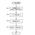
- FIG. 12 is a flowchart showing data correction processing in one embodiment.
- the control unit 110 divides the sound generation control data 125 at the beat positions DBT1, DBT2, . (step S331).
- the control unit 110 expands or contracts each of the plurality of divided data sections to a length corresponding to the section length corresponding to the average tempo (the length of one beat corresponding to the average tempo).
- the position of each pronunciation included in each data section, that is, the timing information is corrected (step S333).
- the control unit 110 adds correction information according to the correction amount of the timing information to each data section (step S335), and combines the plurality of data sections to which the correction information with the corrected timing information is added (step S337). .
- Data correction processing will be described in more detail with reference to FIGS. 13 and 14.
- FIG. 13 and 14 Data correction processing will be described in more detail with reference to FIGS. 13 and 14.
- FIG. 13 is a diagram for explaining an example of correcting timing information.
- FIG. 13 shows an example of correcting the timing information in the data section between beat position DBT4 and beat position DBT5 among a plurality of data sections.
- "After division” indicates the sound generation control data 125 in the data section before correction.
- "Corrected” indicates the sound generation control data 125 after correcting the timing information.
- the data section length before correction corresponds to tempo "110".
- the average tempo is set to "120". Therefore, the data section length is changed to a length corresponding to the tempo "120". Since the length of the data section is multiplied by "110/120", the pronunciation timing information included in this data section is corrected to a position multiplied by "110/120” based on the beginning of the beat (beat position DBT4). . Thus, the correction amount is "110/120".
- the correction information is added as a tempo value "110" corresponding to the original data section length as a value corresponding to the correction amount at a position corresponding to the beat position DBT4. It may be added as a relative value to the average tempo as "110/120". If the data is in MIDI format, it is added as tempo change information.
- FIG. 14 is a diagram for comparing and explaining sound generation control data before and after change.
- FIG. 14 shows the relationship between the timing information of the sound generation control data 125 and the positions of beats "during recording" and "after combining".
- "When recording” indicates the sound generation control data 125 when recorded in the recording mode, that is, before the timing information is changed by the AI quantize process.
- “After combining” indicates the sound generation control data 125 after combining the data sections to which the timing information has been corrected by AI quantization processing and the correction information has been added, that is, after the timing information has been changed. As shown in FIG.
- the AI quantize process aligns the detected beats (or further corrected beats) to a predetermined tempo (average tempo in this example) so that the length of the original beat can be identified.
- the sound generation control data 125 is changed by adding correction information corresponding to the correction amount (in this example, the tempo value corresponding to the original beat length).
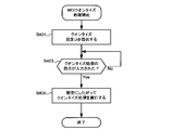
- FIG. 15 is a flowchart showing MIDI quantization processing in one embodiment.
- the control unit 110 provides a quantization setting user interface (quantization processing setting UI) by displaying a screen described below on the display unit 130 (step S401), and waits until an instruction for quantization processing is input ( Step S403; No).
- a quantize process instruction is input (step S403; Yes)
- the control unit 110 executes the quantize process according to the setting (step S405), and ends the MIDI quantize process.
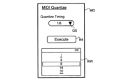
- FIG. 16 is a diagram showing an example of a quantize setting user interface.
- the quantization setting user interface (hereinafter sometimes referred to as interface MD) includes an area QS for setting the resolution of quantization and an execution button B4 for inputting instructions for quantization processing.
- the interface MD contains a window RW for selecting the resolution to be set. If the quantization resolution is "1/8", the timing information is corrected so that the timing is aligned in units of eighth notes.
- This processing is similar to general quantization processing.
- the interface MD may include an area for setting conditions for sounds that are not subject to quantization. A sound not to be quantized may, for example, be moved by the same amount as the nearest quantized sound. Sounds excluded from the quantization process may be, for example, sounds whose length is less than half the resolution, or sounds whose velocity (volume) is lower than a predetermined value. Conversely, the interface MD may include an area in which sounds to be quantized can be specified.
- MIDI quantization process when the rhythm fluctuates during the recording of the sound generation control data 125, it is possible to remove the fluctuation of the rhythm of the sound generation contained in the sound generation control data 125 and align it with the position of the beat. can. This is particularly effective for songs in which rhythm is important, such as dance music.
- rhythm is important, such as dance music.
- FIG. 17 is a flowchart showing delay offset processing in one embodiment.
- the control unit 110 provides an offset setting user interface (offset setting UI: second user interface) by displaying a screen described below on the display unit 130 (step S501), and an instruction for offset processing is input. (Step S503; No).
- offset processing instruction is input (step S503; Yes)
- the control unit 110 executes the offset processing according to the setting (step S505), and ends the delay offset processing.
- FIG. 18 is a diagram showing an example of an offset setting user interface.
- the offset setting user interface (hereinafter sometimes referred to as interface DD) includes an area OS for setting an offset amount and an execution button B5 for inputting an offset processing instruction.
- interface DD includes window RW for selecting the amount of offset to be set. If the offset amount is "30", the sound generation control data 125 is changed by correcting the timing information so as to delay the entire timing by 30 ticks.
- the interface DD may have an area for specifying the sound to be processed.
- the timing information may be corrected for the target sound and a plurality of sounds following the target sound. If the sound to be processed is not specified, the first sound in the pronunciation control data 125 may be specified as the sound to be processed. Two examples of the case where the sound to be processed is designated and corrected will be described with reference to FIGS. 19 and 20.
- FIG. 19 Two examples of the case where the sound to be processed is designated and corrected will be described with reference to FIGS. 19 and 20.
- 19 and 20 are diagrams for comparing and explaining the sound generation control data before and after the delay offset.
- 19 and 20 both show the relationship between the timing information of the sound generation control data 125 and the position of beats "at the time of beat detection” and "after offset”.
- "At time of beat detection” indicates the sound generation control data 125 when beats are detected in the AI quantize process.
- "After offset” indicates the pronunciation control data 125 after the ornamental tone NTs has been designated as the sound to be processed and the offset processing has been performed. Since it is assumed that the grace note is aligned with the beat position by the offset processing, it is assumed that the offset amount is specified so as to move the grace note NTs to the beat position DBT6.
- the timing information is similarly corrected so that the grace note NTs moves to the beat position DBT6.
- the timing information is corrected such that the further away from the ornamental tone NTs, the smaller the offset amount.
- the timing information may be corrected only for sounds within a predetermined number of beats (for example, within four beats) from the grace note NTs.
- Portable device 10 outputs a sound generation instruction signal based on sound generation control data 125 to electronic musical instrument 80 so that sound waveform signal is reproduced in sound source unit 830 .
- modes for reproducing the sound generation control data 125 include an auto mode and a control mode.
- the sound generation control data 125 is read out at a predetermined tempo, and the tempo is corrected using the correction information set corresponding to each beat, thereby substantially correcting the position of the beat and reproducing the sound waveform.
- This mode realizes signal playback and reproduces the performance sound when the data was recorded. If the correction information is not used when reading the sound generation control data 125, as shown in FIG. By changing the reading speed, it is possible to reproduce the performance sound when the data was recorded.
- the sounding control data 125 is read at a predetermined tempo because correction information is not included.
- the ornaments may be desirable to correct the ornaments so that they match the beat position. Ornaments are often positioned slightly before the position of the beat. In such a case, it is desirable that the ornamented tone present at the position of the beat and the ornamental note present before it are reproduced continuously.
- the ornament sounds are reproduced at an early timing, and the ornament sound and the ornamented sound are reproduced with a large gap between them. situation arises. Assuming such a case, by correcting the timing information so that the ornament is positioned at the position of the beat, it is possible to reproduce the ornament and the ornamented tone as one unit without separating them. can.
- FIG. 21 is a flowchart showing data reproduction processing in one embodiment.
- the control unit 110 provides a playback user interface (playback UI) by displaying a screen described below on the display unit 130 (step S801), and waits until an instruction to start data playback is input (step S803). ; No).
- playback UI playback user interface
- control unit 110 controls sound generation by reproducing sound generation control data 125 until an instruction to stop data reproduction is input (step S821; No). Execute the process.
- the control unit 110 executes sound generation control processing in the auto mode (step S813).
- the auto mode is not selected, that is, when the control mode is selected as the reproduction mode (step S813; No)
- sound generation control processing in the control mode is executed (step S815).
- control unit 110 terminates the data reproduction process.
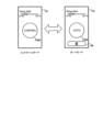
- FIG. 22 is a diagram showing an example of a playback user interface.
- the playback user interface (hereinafter sometimes referred to as interface PD) includes a switch button PMB for switching between auto mode and control mode.
- the switch button PMB includes an image that indicates whether it is operating in auto mode or in control mode. It may be selected so that the mode is switched each time the switching button PMB is operated, or one of the modes (for example, the control mode) is switched while the switching button PMB is being operated (while the switching button PMB is being touched). It may be selected.
- a stop button B6 When operating in auto mode, a stop button B6 is displayed to stop the progress of the song. In the control mode, if the user stops swinging the mobile device 10, the song will stop progressing. Therefore, the stop button B6 does not have to be displayed as shown in FIG. Operating the stop button B6 corresponds to inputting an instruction to stop data reproduction (step S821; Yes). good.
- the sound generation control data 125 recorded according to the performance can be changed to data that can be used in a plurality of different reproduction methods such as the auto mode and the control mode. can be done. It is also possible to change the sound generation control data 125 by selecting an appropriate change method depending on the song.
- correction information was added for each beat, but may be added for every two or more beats, or may be added for each sound. .
- the interface SD allows selection of a process of analyzing an image of a musical score, extracting bar lines, musical notes, performance symbols, etc., and correcting the timing information of the sound generation control data 125 based on the extracted information. good too.
- a data modification method of the present disclosure provides a selection user interface for selecting a modification method to be applied to pronunciation control data defining pronunciation timing information from a plurality of modification methods including a first modification method and a second modification method. and correcting the timing information when applying the first change method is selected, and providing correction information corresponding to the amount of correction of the timing information in the data section for a predetermined data section. modifying the pronunciation control data by adding, and correcting the timing information based on beat positions according to a predetermined tempo when applying the second modification method is selected; modifying the pronunciation control data.
- the data change method of the present disclosure may provide a recording user interface for setting a tempo and instructing performance recording, and when the start of performance recording is instructed, beat information is recorded at the set tempo.
- the sound control data may be recorded based on performance information input while the beat information is being provided, and when an instruction to stop the performance recording is given, the recorded sound control data may be
- a selection user interface may be provided for selecting the modification method to be applied to.
- the plurality of modification methods may further include a third modification method, and when applying the third modification method is selected, specified predetermined pronunciation timing information and timing information of a plurality of pronunciations following the predetermined pronunciation may be changed to change the pronunciation control data.
- the data modification method of the present disclosure may further include providing beat information at a predetermined tempo, and recording the sound generation control data based on performance information input while providing the beat information. , the correction information may be added corresponding to the timing of providing the beat information.
- Detecting the positions of the plurality of beats may include converting the pronunciation control data into audio data and detecting the positions of the plurality of beats based on the audio data.
- the data modification method of the present disclosure may further include providing a first user interface for correcting the detected beat position, wherein modifying the pronunciation control data comprises: and correcting the timing information based on the relationship between the positions of the plurality of beats and the set tempo after being corrected via the method.
- the data modification method of the present disclosure provides a recording user interface for instructing recording of a performance, and when an instruction to start recording the performance is given, the method defines pronunciation timing information based on input performance information.
- a change method to be applied to the recorded sound generation control data is selected from a plurality of change methods including a first change method and a second change method.
- the present disclosure can also be used as a program for causing a computer to execute the data modification method or the data reproduction method, and can be used as a data modification device for executing the data modification method and a data reproduction device for executing the data reproduction method.
- a program for causing a computer to execute the data modification method or the data reproduction method can be used as a data modification device for executing the data modification method and a data reproduction device for executing the data reproduction method.
- at least part of the portable device 10 can function as a data modification device or a data reproduction device.
- 10 portable device, 110: control unit, 120: storage unit, 121: program, 123: performance recording data, 125: sound generation control data, 130: display unit, 140: operation unit, 150: sensor unit, 170: speaker, 180: communication unit, 190: interface, 80: electronic musical instrument, 810: performance operator, 830: sound source unit, 870: speaker, 890: interface, 90: data management server, 910: control unit, 920: storage unit, 980 : Communications department
Landscapes
- Engineering & Computer Science (AREA)
- Physics & Mathematics (AREA)
- Multimedia (AREA)
- Theoretical Computer Science (AREA)
- General Engineering & Computer Science (AREA)
- Acoustics & Sound (AREA)
- Human Computer Interaction (AREA)
- General Physics & Mathematics (AREA)
- Health & Medical Sciences (AREA)
- Audiology, Speech & Language Pathology (AREA)
- General Health & Medical Sciences (AREA)
- Electrophonic Musical Instruments (AREA)
Priority Applications (4)
| Application Number | Priority Date | Filing Date | Title |
|---|---|---|---|
| JP2023544924A JP7683706B2 (ja) | 2021-09-02 | 2021-09-02 | データ変更方法、データ再生方法、およびプログラム |
| PCT/JP2021/032374 WO2023032137A1 (ja) | 2021-09-02 | 2021-09-02 | データ変更方法、データ再生方法、プログラムおよびデータ変更装置 |
| CN202180102029.9A CN117882129A (zh) | 2021-09-02 | 2021-09-02 | 数据变更方法、数据再现方法、程序以及数据变更装置 |
| US18/592,589 US20240203458A1 (en) | 2021-09-02 | 2024-03-01 | Data modification method, data reproduction method, program, data modification device |
Applications Claiming Priority (1)
| Application Number | Priority Date | Filing Date | Title |
|---|---|---|---|
| PCT/JP2021/032374 WO2023032137A1 (ja) | 2021-09-02 | 2021-09-02 | データ変更方法、データ再生方法、プログラムおよびデータ変更装置 |
Related Child Applications (1)
| Application Number | Title | Priority Date | Filing Date |
|---|---|---|---|
| US18/592,589 Continuation US20240203458A1 (en) | 2021-09-02 | 2024-03-01 | Data modification method, data reproduction method, program, data modification device |
Publications (1)
| Publication Number | Publication Date |
|---|---|
| WO2023032137A1 true WO2023032137A1 (ja) | 2023-03-09 |
Family
ID=85410831
Family Applications (1)
| Application Number | Title | Priority Date | Filing Date |
|---|---|---|---|
| PCT/JP2021/032374 Ceased WO2023032137A1 (ja) | 2021-09-02 | 2021-09-02 | データ変更方法、データ再生方法、プログラムおよびデータ変更装置 |
Country Status (4)
| Country | Link |
|---|---|
| US (1) | US20240203458A1 (https=) |
| JP (1) | JP7683706B2 (https=) |
| CN (1) | CN117882129A (https=) |
| WO (1) | WO2023032137A1 (https=) |
Citations (1)
| Publication number | Priority date | Publication date | Assignee | Title |
|---|---|---|---|---|
| JPH10177382A (ja) * | 1996-12-18 | 1998-06-30 | Kawai Musical Instr Mfg Co Ltd | 電子楽器の自動演奏装置 |
Family Cites Families (4)
| Publication number | Priority date | Publication date | Assignee | Title |
|---|---|---|---|---|
| US8198525B2 (en) * | 2009-07-20 | 2012-06-12 | Apple Inc. | Collectively adjusting tracks using a digital audio workstation |
| US20120294457A1 (en) * | 2011-05-17 | 2012-11-22 | Fender Musical Instruments Corporation | Audio System and Method of Using Adaptive Intelligence to Distinguish Information Content of Audio Signals and Control Signal Processing Function |
| US9536567B2 (en) * | 2011-09-02 | 2017-01-03 | Nexidia Inc. | Transcript re-sync |
| US12020723B2 (en) * | 2020-04-27 | 2024-06-25 | Avid Technology, Inc. | Embedded plug-in presentation and control of time-based media documents |
-
2021
- 2021-09-02 JP JP2023544924A patent/JP7683706B2/ja active Active
- 2021-09-02 CN CN202180102029.9A patent/CN117882129A/zh active Pending
- 2021-09-02 WO PCT/JP2021/032374 patent/WO2023032137A1/ja not_active Ceased
-
2024
- 2024-03-01 US US18/592,589 patent/US20240203458A1/en active Pending
Patent Citations (1)
| Publication number | Priority date | Publication date | Assignee | Title |
|---|---|---|---|---|
| JPH10177382A (ja) * | 1996-12-18 | 1998-06-30 | Kawai Musical Instr Mfg Co Ltd | 電子楽器の自動演奏装置 |
Also Published As
| Publication number | Publication date |
|---|---|
| JP7683706B2 (ja) | 2025-05-27 |
| US20240203458A1 (en) | 2024-06-20 |
| CN117882129A (zh) | 2024-04-12 |
| JPWO2023032137A1 (https=) | 2023-03-09 |
Similar Documents
| Publication | Publication Date | Title |
|---|---|---|
| CN101103386A (zh) | 用于乐谱捕捉和带同步呈现的合成音频演奏的系统与方法 | |
| WO2019058942A1 (ja) | 再生制御方法、再生制御装置およびプログラム | |
| JP7683706B2 (ja) | データ変更方法、データ再生方法、およびプログラム | |
| JP7747178B2 (ja) | データ出力方法、プログラム、データ出力装置および電子楽器 | |
| JP2013200455A (ja) | 演奏練習支援システム | |
| WO2020145209A1 (ja) | 映像制御システム、及び映像制御方法 | |
| JP7425558B2 (ja) | コード検出装置及びコード検出プログラム | |
| JP5029258B2 (ja) | 演奏練習支援装置および演奏練習支援処理のプログラム | |
| JP2004302011A (ja) | 指揮棒の振りタイミングに同期させて演奏する装置 | |
| JP4315116B2 (ja) | 電子音楽装置 | |
| JP4305315B2 (ja) | 自動演奏データ特性変更装置及びそのプログラム | |
| JP4853054B2 (ja) | 演奏データ編集装置及びプログラム | |
| JP2005128208A (ja) | 演奏再生装置及び演奏再生制御プログラム | |
| JP5888295B2 (ja) | 演奏情報表示装置、プログラム | |
| JP2015138160A (ja) | キャラクタ演奏画像生成装置、キャラクタ演奏画像生成方法、キャラクタ演奏システム及びキャラクタ演奏方法 | |
| JP2006091804A (ja) | 自動演奏装置及びプログラム | |
| JP7509127B2 (ja) | 情報処理装置、電子楽器システム、電子楽器、音節進行制御方法及びプログラム | |
| JP5145875B2 (ja) | 演奏練習支援装置および演奏練習支援処理のプログラム | |
| JP5402167B2 (ja) | アルペジオ生成装置およびアルペジオ生成方法を実現するためのプログラム | |
| van Eck | Moving for machines: how performing with sensors results in a new virtuosity | |
| JP4515382B2 (ja) | レコーダ | |
| JPH10254443A (ja) | パンチイン装置、パンチイン方法及びプログラムを記録した媒体 | |
| JP3797181B2 (ja) | 楽譜表示装置及び楽譜表示プログラム | |
| WO2025159007A1 (ja) | 情報処理システム、動画編集方法およびプログラム | |
| WO2022209557A1 (ja) | 電子楽器、電子楽器の制御方法、及びプログラム |
Legal Events
| Date | Code | Title | Description |
|---|---|---|---|
| 121 | Ep: the epo has been informed by wipo that ep was designated in this application |
Ref document number: 21956026 Country of ref document: EP Kind code of ref document: A1 |
|
| WWE | Wipo information: entry into national phase |
Ref document number: 202180102029.9 Country of ref document: CN Ref document number: 2023544924 Country of ref document: JP |
|
| NENP | Non-entry into the national phase |
Ref country code: DE |
|
| 122 | Ep: pct application non-entry in european phase |
Ref document number: 21956026 Country of ref document: EP Kind code of ref document: A1 |