WO2023032052A1 - ステントおよびステントデリバリーシステム - Google Patents
ステントおよびステントデリバリーシステム Download PDFInfo
- Publication number
- WO2023032052A1 WO2023032052A1 PCT/JP2021/032009 JP2021032009W WO2023032052A1 WO 2023032052 A1 WO2023032052 A1 WO 2023032052A1 JP 2021032009 W JP2021032009 W JP 2021032009W WO 2023032052 A1 WO2023032052 A1 WO 2023032052A1
- Authority
- WO
- WIPO (PCT)
- Prior art keywords
- intersection
- stent
- straight
- valley
- straight line
- Prior art date
- Legal status (The legal status is an assumption and is not a legal conclusion. Google has not performed a legal analysis and makes no representation as to the accuracy of the status listed.)
- Ceased
Links
Images











Classifications
-
- A—HUMAN NECESSITIES
- A61—MEDICAL OR VETERINARY SCIENCE; HYGIENE
- A61F—FILTERS IMPLANTABLE INTO BLOOD VESSELS; PROSTHESES; DEVICES PROVIDING PATENCY TO, OR PREVENTING COLLAPSING OF, TUBULAR STRUCTURES OF THE BODY, e.g. STENTS; ORTHOPAEDIC, NURSING OR CONTRACEPTIVE DEVICES; FOMENTATION; TREATMENT OR PROTECTION OF EYES OR EARS; BANDAGES, DRESSINGS OR ABSORBENT PADS; FIRST-AID KITS
- A61F2/00—Filters implantable into blood vessels; Prostheses, i.e. artificial substitutes or replacements for parts of the body; Appliances for connecting them with the body; Devices providing patency to, or preventing collapsing of, tubular structures of the body, e.g. stents
- A61F2/82—Devices providing patency to, or preventing collapsing of, tubular structures of the body, e.g. stents
- A61F2/86—Stents in a form characterised by the wire-like elements; Stents in the form characterised by a net-like or mesh-like structure
- A61F2/90—Stents in a form characterised by the wire-like elements; Stents in the form characterised by a net-like or mesh-like structure characterised by a net-like or mesh-like structure
-
- A—HUMAN NECESSITIES
- A61—MEDICAL OR VETERINARY SCIENCE; HYGIENE
- A61F—FILTERS IMPLANTABLE INTO BLOOD VESSELS; PROSTHESES; DEVICES PROVIDING PATENCY TO, OR PREVENTING COLLAPSING OF, TUBULAR STRUCTURES OF THE BODY, e.g. STENTS; ORTHOPAEDIC, NURSING OR CONTRACEPTIVE DEVICES; FOMENTATION; TREATMENT OR PROTECTION OF EYES OR EARS; BANDAGES, DRESSINGS OR ABSORBENT PADS; FIRST-AID KITS
- A61F2/00—Filters implantable into blood vessels; Prostheses, i.e. artificial substitutes or replacements for parts of the body; Appliances for connecting them with the body; Devices providing patency to, or preventing collapsing of, tubular structures of the body, e.g. stents
- A61F2/82—Devices providing patency to, or preventing collapsing of, tubular structures of the body, e.g. stents
- A61F2/86—Stents in a form characterised by the wire-like elements; Stents in the form characterised by a net-like or mesh-like structure
- A61F2/88—Stents in a form characterised by the wire-like elements; Stents in the form characterised by a net-like or mesh-like structure the wire-like elements formed as helical or spiral coils
-
- A—HUMAN NECESSITIES
- A61—MEDICAL OR VETERINARY SCIENCE; HYGIENE
- A61F—FILTERS IMPLANTABLE INTO BLOOD VESSELS; PROSTHESES; DEVICES PROVIDING PATENCY TO, OR PREVENTING COLLAPSING OF, TUBULAR STRUCTURES OF THE BODY, e.g. STENTS; ORTHOPAEDIC, NURSING OR CONTRACEPTIVE DEVICES; FOMENTATION; TREATMENT OR PROTECTION OF EYES OR EARS; BANDAGES, DRESSINGS OR ABSORBENT PADS; FIRST-AID KITS
- A61F2/00—Filters implantable into blood vessels; Prostheses, i.e. artificial substitutes or replacements for parts of the body; Appliances for connecting them with the body; Devices providing patency to, or preventing collapsing of, tubular structures of the body, e.g. stents
- A61F2/95—Instruments specially adapted for placement or removal of stents or stent-grafts
-
- D—TEXTILES; PAPER
- D04—BRAIDING; LACE-MAKING; KNITTING; TRIMMINGS; NON-WOVEN FABRICS
- D04C—BRAIDING OR MANUFACTURE OF LACE, INCLUDING BOBBIN-NET OR CARBONISED LACE; BRAIDING MACHINES; BRAID; LACE
- D04C1/00—Braid or lace, e.g. pillow-lace; Processes for the manufacture thereof
- D04C1/06—Braid or lace serving particular purposes
-
- A—HUMAN NECESSITIES
- A61—MEDICAL OR VETERINARY SCIENCE; HYGIENE
- A61F—FILTERS IMPLANTABLE INTO BLOOD VESSELS; PROSTHESES; DEVICES PROVIDING PATENCY TO, OR PREVENTING COLLAPSING OF, TUBULAR STRUCTURES OF THE BODY, e.g. STENTS; ORTHOPAEDIC, NURSING OR CONTRACEPTIVE DEVICES; FOMENTATION; TREATMENT OR PROTECTION OF EYES OR EARS; BANDAGES, DRESSINGS OR ABSORBENT PADS; FIRST-AID KITS
- A61F2220/00—Fixations or connections for prostheses classified in groups A61F2/00 - A61F2/26 or A61F2/82 or A61F9/00 or A61F11/00 or subgroups thereof
- A61F2220/0008—Fixation appliances for connecting prostheses to the body
-
- A—HUMAN NECESSITIES
- A61—MEDICAL OR VETERINARY SCIENCE; HYGIENE
- A61F—FILTERS IMPLANTABLE INTO BLOOD VESSELS; PROSTHESES; DEVICES PROVIDING PATENCY TO, OR PREVENTING COLLAPSING OF, TUBULAR STRUCTURES OF THE BODY, e.g. STENTS; ORTHOPAEDIC, NURSING OR CONTRACEPTIVE DEVICES; FOMENTATION; TREATMENT OR PROTECTION OF EYES OR EARS; BANDAGES, DRESSINGS OR ABSORBENT PADS; FIRST-AID KITS
- A61F2230/00—Geometry of prostheses classified in groups A61F2/00 - A61F2/26 or A61F2/82 or A61F9/00 or A61F11/00 or subgroups thereof
- A61F2230/0063—Three-dimensional shapes
- A61F2230/0069—Three-dimensional shapes cylindrical
-
- A—HUMAN NECESSITIES
- A61—MEDICAL OR VETERINARY SCIENCE; HYGIENE
- A61F—FILTERS IMPLANTABLE INTO BLOOD VESSELS; PROSTHESES; DEVICES PROVIDING PATENCY TO, OR PREVENTING COLLAPSING OF, TUBULAR STRUCTURES OF THE BODY, e.g. STENTS; ORTHOPAEDIC, NURSING OR CONTRACEPTIVE DEVICES; FOMENTATION; TREATMENT OR PROTECTION OF EYES OR EARS; BANDAGES, DRESSINGS OR ABSORBENT PADS; FIRST-AID KITS
- A61F2240/00—Manufacturing or designing of prostheses classified in groups A61F2/00 - A61F2/26 or A61F2/82 or A61F9/00 or A61F11/00 or subgroups thereof
- A61F2240/001—Designing or manufacturing processes
- A61F2240/002—Designing or making customized prostheses
-
- A—HUMAN NECESSITIES
- A61—MEDICAL OR VETERINARY SCIENCE; HYGIENE
- A61F—FILTERS IMPLANTABLE INTO BLOOD VESSELS; PROSTHESES; DEVICES PROVIDING PATENCY TO, OR PREVENTING COLLAPSING OF, TUBULAR STRUCTURES OF THE BODY, e.g. STENTS; ORTHOPAEDIC, NURSING OR CONTRACEPTIVE DEVICES; FOMENTATION; TREATMENT OR PROTECTION OF EYES OR EARS; BANDAGES, DRESSINGS OR ABSORBENT PADS; FIRST-AID KITS
- A61F2310/00—Prostheses classified in A61F2/28 or A61F2/30 - A61F2/44 being constructed from or coated with a particular material
- A61F2310/00005—The prosthesis being constructed from a particular material
- A61F2310/00011—Metals or alloys
Definitions
- the present invention relates to stents and stent delivery systems.
- a procedure is known in which a stent is placed and expanded for stenosis or obstruction (hereinafter referred to as "stenosis, etc.") that occurs in the digestive tract.
- a stent delivery system is used to place a stent in a stenosis or the like.
- a stent delivery system passes through a treatment instrument channel of an endoscope to deliver a stent to a stenosis or the like.
- the stent described in Patent Document 1 is constructed by winding a single wire around a pin attached to a jig and weaving it like a fence. Since the stent has a portion (interlocking portion 60) where two curved shapes are interlocked with each other, it has high shape followability even when it is bent, and easily adapts to the topography of the lumen in which it is placed. It has the characteristics of
- the portion where the straight wires cross each other is the portion adjacent to the meshing portion 60 in the circumferential direction of the stent. located in When the stent is bent, the interlocking portions 60 can bend accordingly, but the linear intersection portions 70 generate a force (axial force) that repels the bending, which impairs the shape followability of the stent as a whole.
- the shape of the lumen is greatly curved, it is difficult to place the stent, or even if it can be placed, the lumen will try to follow the shape of the stent, causing a burden on the lumen. Problems can occur, such as overheating and the stent moving out of its deployed position.
- an object of the present invention is to provide a stent that is easy to bend and maintain a bent state, and a stent delivery system that includes the stent.
- a stent according to a first aspect of the present invention is a stent formed by weaving wires, wherein at least two straight portions of the wires intersect so that they are adjacent to each other in the circumferential direction of the stent.
- a plurality of straight crossing portions arranged in the longitudinal direction of the stent, a mountain-shaped bending portion in which the wire is bent in a first direction that is one of the longitudinal axis directions of the stent and becomes convex, and the wire is in the longitudinal axis direction
- a plurality of engaging portions arranged so as to be adjacent to each other in the circumferential direction of the stent. and, wherein the engaging portions and the linear intersection portions are alternately arranged in the longitudinal axis direction.
- a delivery system comprises an operating portion, an outer cylinder member configured to extend distally from the operating portion, and an outer cylinder member configured to extend distally from the operating portion. , an inner tubular member located inside the outer tubular member, and the stent accommodated between the outer tubular member and the inner tubular member, wherein the operation section is the outer tubular member or the inner tubular member. longitudinally displacing the stent.
- the stent of the present invention is easy to bend and easy to maintain the bent state.
- FIG. 2 is a developed view of the stent developed in the circumferential direction;
- FIG. 2 is an exploded view of the same stent including a partially enlarged view;
- It is a figure which shows the intersection of a 1st straight part and another wire.
- It is a figure which shows the modification of the intersection aspect of a wire.
- It is a figure which shows the cross
- FIG. 4 is a developed view of the stent according to the second embodiment of the present invention developed in the circumferential direction; It is a figure which shows the modification of arrangement
- FIG. 4 is a developed view of the stent according to the second embodiment of the present invention developed in the circumferential direction; It is a figure which shows the modification of arrangement
- FIG. 4 is a developed view of the stent according to the third embodiment of the present invention developed in the circumferential direction; It is a figure which shows the modification of arrangement
- FIG. 11 is a developed view of the stent according to the fourth embodiment of the present invention, developed in the circumferential direction; It is a figure which shows the modification of arrangement
- FIG. 11 is a developed view of the stent according to the fifth embodiment of the present invention, developed in the circumferential direction; It is a figure which shows the modification of arrangement
- FIG. 11 is a diagram showing another modification of the arrangement of the first straight line intersection and the second straight line intersection.
- FIG. 11 is a diagram showing another modification of the arrangement of the first straight line intersection and the second straight line intersection.
- FIG. 11 is a diagram showing another modification of the arrangement of the first straight line intersection and the second straight line intersection.
- FIG. 11 is a diagram showing another modification of the arrangement of the first straight line intersection and the second straight line intersection. It is a figure which shows the modification of the arrangement
- FIG. 1 is a diagram showing the overall configuration of an endoscope system 300. As shown in FIG.
- the endoscope system 300 includes an endoscope 200 and a stent delivery system 150 inserted through a channel of the endoscope 200.
- the endoscope 200 is a known side-viewing flexible endoscope, and includes an elongated insertion section 210 and an operation section 220 provided at the proximal end of the insertion section 210 . Note that the endoscope 200 may be a direct-view flexible endoscope.
- the insertion section 210 includes a distal rigid portion 211 provided at the distal end portion, a bendable bending portion 212 provided at the proximal end side of the distal rigid portion 211, and a flexible portion provided at the proximal end side of the bending portion 212. and a flexible tube portion 213 .
- An imaging unit 216 having a light guide 215 and a CCD is provided on the side surface of the distal end rigid portion 211 in a state of being exposed to the outside.
- the insertion portion 210 is formed with a treatment instrument channel 230 through which an endoscopic treatment instrument such as the stent delivery system 150 is inserted.
- a distal end portion 230 a of the treatment instrument channel 230 is open on the side surface of the distal end rigid portion 211 .
- a proximal end portion of the treatment instrument channel 230 extends to the operating portion 220 .
- a riser 214 is provided on the distal end hard portion 211 of the treatment instrument channel 230 .
- a base end portion of the raising base 214 is rotatably supported by the distal end rigid portion 211 .
- An elevator operating wire (not shown) fixed to the distal end of the elevator 214 extends through the insertion section 210 toward the proximal end.
- the bending portion 212 is configured to be freely bendable in the vertical and horizontal directions.
- the distal end of the operation wire is fixed to the distal end side of the bending portion 212 .
- the operation wire extends through the insertion portion 210 to the operation portion 220 .
- a knob 223 for operating the operation wire and a switch 224 for operating the imaging unit 216 and the like are provided on the proximal end side of the operation section 220 .
- the user can bend the bending portion 212 in a desired direction by operating the knob 223 .
- a forceps port 222 that communicates with the treatment instrument channel 230 is provided on the distal end side of the operation portion 220 .
- a user can insert an endoscopic instrument such as the stent delivery system 150 through the forceps port 222 .
- a forceps plug 225 is attached to the forceps port 222 to prevent leakage of bodily fluids.
- the stent delivery system 150 is elongated as a whole and includes a stent 100 , an outer tubular member 110 , an inner tubular member 120 and an operating section 140 .
- the outer cylindrical member 110 is made of resin or the like in a cylindrical shape and has flexibility. Outer cylinder member 110 can be inserted through treatment instrument channel 230 of endoscope 200 .
- the inner cylinder member 120 has an outer diameter smaller than the inner diameter of the outer cylinder member 110 and can be passed through the inner space (lumen) of the outer cylinder member 110 .
- the inner cylindrical member 120 is made of resin or the like and has flexibility.
- a tip 130 having an outer diameter larger than that of the outer cylinder member 110 is provided at the tip of the inner cylinder member 120 .
- the stent 100 is housed at the distal end of the stent delivery system 150, as shown in FIG.
- the stent 100 is accommodated in the gap between the inner tubular member 120 and the outer tubular member 110 in a state in which the inner tubular member 120 is passed through the inside thereof and the diameter thereof is reduced.
- the operation part 140 is connected to the base end sides of the outer cylinder member 110 and the inner cylinder member 120, and is configured to allow the outer cylinder member 110 to move relative to the inner cylinder member 120 in the longitudinal direction.
- the operator moves the outer tube member 110 with respect to the inner tube member 120 to expose the accommodated stent 100, and as a result, the stent 100 can be placed.
- the operator can move the outer tube member 110 in the opposite direction relative to the inner tube member 120, thereby allowing the stent 100 to be re-accommodated.
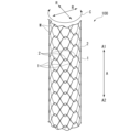
- FIG. 2 is a diagram showing the overall configuration of the stent 100. As shown in FIG.
- the stent 100 is formed by weaving wires and has a cylindrical shape.
- the stent 100 is indwelled in a digestive system body lumen such as a bile duct, esophagus, duodenum, small intestine, large intestine, etc., and is used mainly for the purpose of expanding and maintaining the lumen.
- a digestive system body lumen such as a bile duct, esophagus, duodenum, small intestine, large intestine, etc.
- the stent 100 of this embodiment is not a so-called covered stent whose outer peripheral surface side is covered with a resin film or the like, but an uncovered stent that is not covered with a film or the like.
- the stent 100 can also be used as a covered stent by being covered with a resin film or the like.
- first direction A1 one of the longitudinal axis directions (axial directions) A of the stent 100
- second direction A2 one of the longitudinal axis directions A of the stent 100
- FIG. 3 is a developed view of the stent 100 deployed in the circumferential direction C.
- the stent 100 is formed in the shape of a circular tube having meshes on its peripheral surface by wires W that extend obliquely in the circumferential direction C while repeatedly bending.
- the stent 100 has a plurality of straight crossing portions 1 and a plurality of hooking portions 2 .
- FIG. 4 is an exploded view of stent 100 including an enlarged partial view.
- the straight line crossing portion 1 is formed by the straight line portions 10 of the wires W crossing each other.
- the straight portion 10 is a substantially straight portion of the wire W and includes a gently curved portion.
- the engaging portion (entangled portion) 2 is formed by intersecting the mountain-shaped bent portion 3 and the valley-shaped bent portion 4 .
- the mountain-shaped bent portion (mountain) 3 is a convex portion in which the wire W extending obliquely in the circumferential direction C is folded back in the longitudinal axis direction A and convexes in the first direction A1.
- the valley-shaped bent portion (trough) 4 is a convex portion (concave in the first direction A1 side) in which the wire W extending in the circumferential direction is folded back in the longitudinal direction A and bent in the second direction A2 side (concave in the first direction A1 side). concave).
- the mountain-shaped bent portion 3 and the valley-shaped bent portion 4 intersect each other in a hook shape, so that the mountain-shaped bent portion 3 and the valley-shaped bent portion 4 are connected so as to be relatively movable although they cannot be separated. be done.
- the first regions E1 in which the plurality of straight line crossing portions 1 are arranged and the second regions E2 in which the plurality of engaging portions 2 are arranged are alternately arranged in the longitudinal axis direction A.
- the first region E1 is spirally arranged along the longitudinal axis direction A.
- the second region E2 is spirally arranged along the longitudinal axis direction A.
- the end region E3 of the stent 100 on the second direction A2 side is arranged parallel to the circumferential direction C without the valley-shaped bends 4 intersecting the mountain-shaped bends 3 .
- the end region (not shown) of the stent 100 on the first direction A1 side is arranged parallel to the circumferential direction C without the mountain-shaped bent portions 3 intersecting the valley-shaped bent portions 4 .
- First engagement portion 21 A “first mountain 31 ”, which is the mountain-shaped bent portion 3 , continues on the first direction A ⁇ b>1 side of the first straight portion 11 .
- the first peak 31 intersects with the first valley 41 that is the valley-shaped bent portion 4 to form the “first engaging portion 21 ” that is the engaging portion 2 .
- the first crest 31 and the first valley 41 are located at the first intersection C1 and the second intersection closer to the central straight intersection 1A than the first intersection C1. It intersects with the part C2.
- the first crest 31 passes through the outer side of the first valley 41 in the radial direction R.
- the first crest 31 passes through the inner side of the first valley 41 in the radial direction R.
- the second peak 32 intersects with the second valley 42 that is the valley-shaped bent portion 4 to form the “second hooking portion 22 ” that is the hooking portion 2 .
- the second crest 32 and the second valley 42 are located at a sixth intersection closer to the central straight intersection 1A than the fifth intersection C5 and the fifth intersection C5. It intersects with the part C6.
- the second peak 32 passes inside the second valley 42 in the radial direction R.
- the second peak 32 passes outside the second valley 42 in the radial direction R.
- the third valley 43 intersects with the third peak 33 that is the mountain-shaped bent portion 3 to form the “third engaging portion 23 ” that is the engaging portion 2 .
- the third crest 33 and the third valley 43 are closer to the central straight intersection 1A than the fourth intersection C4 and the fourth intersection C4. It intersects with the part C3.
- the third valley 43 passes inside the third crest 33 in the radial direction R at the third crossing portion C3.
- the third valley 43 passes outside the third crest 33 in the radial direction R at the fourth crossing portion C4.
- the fourth valley 44 intersects with the fourth peak 34 that is the mountain-shaped bent portion 3 to form the "fourth hooking portion 24" that is the hooking portion 2. As shown in FIG.
- the fourth crest 34 and the fourth valley 44 are closer to the central straight intersection 1A than the eighth intersection C8 and the eighth intersection C8. It intersects with the part C7.
- the fourth valley 44 passes outside the fourth crest 34 in the radial direction R at the seventh intersection C7.
- the fourth valley 44 passes inside the fourth crest 34 in the radial direction R at the fourth crossing portion C4.
- the first engaging portion 21 and the second engaging portion 22 are arranged at different positions in the longitudinal axis direction A. As shown in FIG. Specifically, the second engaging portion 22 is arranged on the first direction A1 side of the first engaging portion 21 in the longitudinal axis direction A. As shown in FIG. Also, the first engaging portion 21 is arranged in the longitudinal axis direction A between the second engaging portion 22 and the central straight line intersection portion 1A.
- the third engaging portion 23 and the fourth engaging portion 24 are arranged at different positions in the longitudinal axis direction A. Specifically, the third engaging portion 23 is arranged on the first direction A1 side of the fourth engaging portion 24 in the longitudinal axis direction A. As shown in FIG. Further, the third engaging portion 23 is arranged between the central straight line intersection portion 1A and the fourth engaging portion 24 in the longitudinal axis direction A. As shown in FIG.
- the central straight-line intersection portion 1A is arranged between the first engaging portion 21 and the second engaging portion 22 in the circumferential direction C. Further, the central straight line intersection portion 1A is arranged between the third engaging portion 23 and the fourth engaging portion 24 in the circumferential direction C. As shown in FIG.
- the first crest 31, the first straight portion 11, and the third valley 43 are continuous parts of the wire W extending zigzag along the circumferential direction C, and are parts of the wire W indicated by broken lines in FIG. .
- the wire W indicated by the dashed line in FIG. 4 is also referred to as "first wire W1".
- the second crest 32, the second straight portion 12, and the fourth valley 44 are continuous parts of the wire W extending zigzag along the circumferential direction C, and are parts of the wire W indicated by solid lines in FIG. be.
- the wire W indicated by the solid line in FIG. 4 is also referred to as "second wire W2".
- the first wire W1 and the second wire W2 may be one continuous wire, or may be different wires.
- FIG. 5 is a diagram showing intersections of the first straight portion 11 and other wires W.
- the first crest 31 extending in the first direction A1 passes inside the first valley 41 in the radial direction R at the second crossing portion C2.
- the third valley 43 continuous in the second direction A2 passes inside the third peak 33 in the radial direction R at the third intersecting portion C3. Therefore, as shown in FIG. 5, the first straight portion 11 sandwiched between the second crossing portion C2 and the third crossing portion C3 has a convex shape.
- the frictional force of the wires W intersecting at the second crossing portion C2, the third crossing portion C3 and the central straight crossing portion 1A increases, and the stent 100 tends to maintain its bent state.
- the operator inserts the insertion portion 210 of the endoscope 200 into the patient's body cavity through a natural opening such as the mouth. At that time, the operator bends the bending portion 212 by operating the knob 223 or the like as necessary.
- the operator passes the guidewire through the treatment instrument channel 230 of the endoscope 200 and inserts the guidewire into the bile duct while observing with the endoscope 200 . Subsequently, the operator operates the guidewire under X-ray fluoroscopy to break through the narrowed site in the bile duct, and moves the distal end of the guidewire to the liver side of the narrowed site (target position).
- the operator inserts the proximal end of the guide wire protruding from the forceps plug 225 of the endoscope 200 into the through hole of the tip 130 of the stent delivery system 150 .
- the operator advances the stent delivery system 150 along the guidewire by pushing the stent delivery system 150 while holding the guidewire.
- the distal end of stent delivery system 150 protrudes from the distal end of treatment instrument channel 230 of endoscope 200 .
- the operator advances and retracts the stent delivery system 150 to determine the indwelling position of the stent 100 . Note that the operator may insert the stent delivery system 150 into the treatment instrument channel 230 without using a guide wire.
- the operator After determining the target position of the stent 100 , the operator retracts the outer cylinder member 110 with respect to the inner cylinder member 120 . As a result, as shown in FIG. 1, the stent 100 is gradually exposed and expanded from the distal end side.
- the stent 100 When the stent 100 is completely exposed, the stent 100 expands as a whole and the inner diameter of the stent 100 becomes larger than the outer diameter of the inner tubular member 120 . Along with this, the locking between the stent 100 and the inner tubular member 120 is released.
- the stent 100 After the locking between the stent 100 and the inner tubular member 120 is released, when the operator retracts the inner tubular member 120 , the stent 100 remains at the indwelling position and the inner tubular member 120 is removed from the stent 100 .
- the placement procedure of the stent 100 is completed.
- the stent 100 has a plurality of engaging portions 2 and has high shape followability even when bent. Further, as shown in FIG. 5, since the first straight portion 11 sandwiched between the second intersection C2 and the third intersection C3 is convex, the second intersection C2, the third intersection C3 and the central straight line The frictional force of the wires W intersecting at the crossing portion 1A is increased, and the stent 100 tends to maintain its bent state. As a result, stent 100 is easy to bend and easy to maintain in a bent state.
- the second regions E2 are arranged in a spiral shape, so the stent 100 can be knitted without arranging the straight-line intersections 1 in the second regions E2. That is, in the stent 100, it is not necessary to arrange the linear crossing portion 1 at a position adjacent to the engaging portion 2 in the circumferential direction C. Therefore, in the second region E2, the stent 100 has only the hooking portions 2 having high conformability, and is easy to bend.
- the first regions E1 where the straight crossing portions 1 where the frictional force (locking force) of the intersecting wires W is large are arranged alternately with the second regions E2 in the longitudinal axis direction A. As shown in FIG. Therefore, the stent 100 can preferably maintain its curved shape.
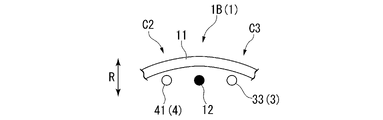
- the crossing manner of the wires W is not limited to the crossing manner shown in FIG.
- FIG. 6 is a diagram showing a modification of the intersecting manner of the wires W.
- FIG. 7 is a diagram showing intersections of the first straight portion 11 and another wire W in the modification.
- the first linear portion 11 has the first peak 31 continuous in the first direction A1 passing outside the first valley 41 in the radial direction R at the second crossing portion C2. do.
- the third valley 43 continuous in the second direction A2 passes outside the third peak 33 in the radial direction R at the third intersecting portion C3. Therefore, as shown in FIG.
- the first straight portion 11 sandwiched between the second crossing portion C2 and the third crossing portion C3 has an arc shape.
- the frictional force of the wires W intersecting at the second crossing portion C2, the third crossing portion C3 and the central straight crossing portion 1B becomes smaller than in the above embodiment, and the stent 100 becomes more bendable.
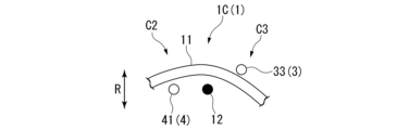
- FIGS. 8A and 8B are diagrams showing another modification of the intersecting manner of the wires W.
- FIG. FIG. 9 is a diagram showing intersections of the first straight portion 11 and another wire W in another modification.
- the first linear portion 11 has the first peak 31 continuous in the first direction A1 passing outside the first valley 41 in the radial direction R at the second crossing portion C2. do.
- the third valley 43 continuous in the second direction A2 passes inside the third peak 33 in the radial direction R at the third intersecting portion C3.
- the frictional force of the wires W intersecting at the second crossing portion C2, the third crossing portion C3, and the central straight crossing portion 1C is smaller than in the above embodiment, and larger than that in Modification 1-1. Become.
- a second embodiment of the present invention will be described with reference to FIG. In the following description, the same reference numerals are given to the same configurations as those already described, and redundant descriptions will be omitted.
- a stent 100B according to the second embodiment is housed in a stent delivery system 150, like the stent 100 according to the first embodiment.
- the intersections of the wires W at the straight crossing portion 1 and the four engaging portions 2 connected to the straight crossing portion 1 were the same at any location.
- the crossing pattern of the wire W at the straight crossing portion 1 and the four hooking portions 2 connected to the straight crossing portion 1 differs depending on the location.
- first straight line intersection portion 1A The central straight line intersection portion 1A of the stent 100 according to the first embodiment will be referred to as "first straight line intersection portion 1A" in the following description.
- the first straight line portion 11 forming the first straight line intersection portion 1A has a first peak 31 extending in the first direction A1 and a first valley 41 at the second intersection portion C2. in the radial direction R.
- the third valley 43 extending in the second direction A2 passes inside the third peak 33 in the radial direction R at the third intersection portion C3.
- the central straight-line intersection 1B shown in Modification 1-1 of the first embodiment will be referred to as "second straight-line intersection 1B" in the following description.
- the first straight line portion 11 forming the second straight line intersection portion 1B has a first peak 31 extending in the first direction A1 and a first valley at the second intersection portion C2. 41 in the radial direction R.
- the third valley 43 continuing on the second direction A2 side passes through the outside of the third crest 33 in the radial direction R at the third intersection portion C3. .
- the second straight-line crossing portion 1B may be a straight-line crossing portion 1 having a different wire W crossing mode such as the central straight-line crossing portion 1C shown in Modification 1-2.
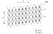
- FIG. 10 is a developed view of the stent 100B deployed in the circumferential direction C.
- the stent 100B has a plurality of linear crossing portions 1 and a plurality of hooking portions 2, like the stent 100 according to the first embodiment.
- the plurality of straight-line intersections 1 includes a first straight-line intersection 1A and a second straight-line intersection 1B.
- the first straight-line intersection portion 1A is arranged continuously in the longitudinal axis direction A. Two or three first straight crossing portions 1A are continuously arranged in the circumferential direction C. As shown in FIG. Moreover, the second straight-line intersection portion 1B is arranged continuously in the longitudinal axis direction A. As shown in FIG. Two or three second straight-line intersection portions 1B are continuously arranged in the circumferential direction C. As shown in FIG. Further, the first straight line intersection portions 1A and the second straight line intersection portions 1B are alternately arranged in the circumferential direction C. As shown in FIG.
- the number of first straight-line intersections 1A and the number of second straight-line intersections 1B are substantially equal.
- the first straight crossing portion 1A where the frictional force of the crossing wires W is high is arranged continuously in the longitudinal axis direction A.
- the second straight crossing portion 1B where the frictional force of the crossing wires W is low is arranged continuously in the longitudinal axis direction A.
- the first straight line intersection portions 1A and the second straight line intersection portions 1B are alternately arranged in the circumferential direction C. As shown in FIG. As a result, the stent 100B can achieve both high shape followability and high shape retention.
- FIG. 11 is a diagram showing a stent 100B1 that is a modification of the arrangement of the first straight crossing portion 1A and the second straight crossing portion 1B.
- the number of first straight crossings 1A is greater than the number of second straight crossings 1B. Therefore, in the stent 100B1, the frictional force of the intersecting wires W is higher than in the stent 100B, and the stent 100B1 is less likely to collapse in the longitudinal direction A.
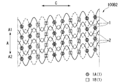
- FIG. 12 is a diagram showing a stent 100B2 that is a modification of the arrangement of the first straight line crossing portion 1A and the second straight line crossing portion 1B.
- 1 A of 1st straight line intersection parts are arrange
- two second straight-line intersection portions 1B are continuously arranged in the circumferential direction C.
- FIG. 12 is a diagram showing a stent 100B2 that is a modification of the arrangement of the first straight line crossing portion 1A and the second straight line crossing portion 1B.
- 1 A of 1st straight line intersection parts are arrange
- two second straight-line intersection portions 1B are continuously arranged in the circumferential direction C.
- FIG. 13 is a diagram showing a stent 100B3 that is a modified example of the arrangement of the first straight line intersection portion 1A and the second straight line intersection portion 1B.
- the first straight line intersection portion 1A and the second straight line intersection portion 1B are arranged alternately one by one in the circumferential direction C.
- Stent 100B3 has higher shape followability and shape retention than stent 100B.
- the stent 100C according to the third embodiment differs from the stent 100B according to the second embodiment only in the arrangement of the first straight intersection portion 1A and the second straight intersection portion 1B.
- FIG. 14 is a developed view of the stent 100C deployed in the circumferential direction C.
- the stent 100C has a plurality of linear crossing portions 1 and a plurality of hooking portions 2, like the stent 100 according to the first embodiment.
- the plurality of straight-line intersections 1 includes a first straight-line intersection 1A and a second straight-line intersection 1B.
- the first straight-line intersection portion 1A and the second straight-line intersection portion 1B are alternately arranged one by one in the longitudinal axis direction A. Also, the first straight line crossing portion 1A and the second straight line crossing portion 1B are alternately arranged in the circumferential direction C one by one.
- the first straight crossing portion 1A where the frictional force of the crossing wires W is high and the second straight crossing portion 1B where the frictional force of the crossing wires W is low are arranged in the longitudinal axis direction A. and in the circumferential direction C, it is possible to achieve both high shape followability and high shape maintainability.
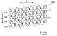
- FIG. 15 is a diagram showing a stent 100C1 that is a modification of the arrangement of the first straight crossing portion 1A and the second straight crossing portion 1B.
- the first straight crossing portion 1A and the second straight crossing portion 1B are alternately arranged in the longitudinal axis direction A one by one.
- the stent 100C1 includes a second region E2A in which one first straight crossing portion 1A and two continuous second straight crossing portions 1B are arranged in the circumferential direction C, two continuous first straight crossing portions 1A and one and a second region E2B arranged in the circumferential direction C with the second straight intersection portion 1B.
- the second regions E2A and the second regions E2B are alternately arranged in the longitudinal direction A one by one.
- the stent 100C1 has higher shape followability than the stent 100C.
- FIG. 16 is a diagram showing a stent 100C2 that is a modification of the arrangement of the first straight crossing portion 1A and the second straight crossing portion 1B.
- Three or four first straight crossing portions 1A are continuously arranged in the circumferential direction C.
- three or four second straight-line intersection portions 1B are continuously arranged in the circumferential direction C.
- the stent 100C2 can achieve both high shape followability and high shape retention.
- a fourth embodiment of the present invention will be described with reference to FIG. In the following description, the same reference numerals are given to the same configurations as those already described, and redundant descriptions will be omitted.
- a stent 100D according to the fourth embodiment differs from the stent 100B according to the second embodiment only in the arrangement of the first straight intersection portion 1A and the second straight intersection portion 1B.
- FIG. 17 is a developed view of the stent 100D deployed in the circumferential direction C.
- the stent 100D has a plurality of linear crossing portions 1 and a plurality of hooking portions 2, like the stent 100 according to the first embodiment.
- the plurality of straight-line intersections 1 includes a first straight-line intersection 1A and a second straight-line intersection 1B.
- the first straight-line intersections 1A are arranged continuously in the circumferential direction C.
- the second straight-line intersection portion 1B is arranged continuously in the circumferential direction C.
- the first straight line intersection portions 1A and the second straight line intersection portions 1B are alternately arranged in the longitudinal axis direction A. As shown in FIG.
- the first straight crossing portions 1A where the frictional force of the crossing wires W is high are arranged continuously in the circumferential direction C, so that it is easy to maintain a certain shape retention.
- the stent 100D can partially retain a portion having a very high shape followability while maintaining a certain shape retention property.
- FIG. 18 is a diagram showing a stent 100D1 that is a modification of the arrangement of the first straight crossing portion 1A and the second straight crossing portion 1B.
- the first straight crossing portions 1A are alternately arranged in the circumferential direction C.
- the second straight crossing portion 1B is not arranged continuously in the circumferential direction C.
- the second straight line crossing portions 1B and the first straight line crossing portions 1A are alternately arranged in the circumferential direction C one by one.
- the stent 100D1 can partially retain a portion with extremely high shape followability while maintaining constant shape retention.
- FIG. 19 is a diagram showing a stent 100D2 that is a modification of the arrangement of the first straight crossing portion 1A and the second straight crossing portion 1B.
- the first straight crossing portions 1A are arranged continuously in the circumferential direction C.
- the second straight crossing portion 1B is not continuously arranged in the circumferential direction C.
- the five continuous second straight line intersections 1B are arranged adjacent to the five continuous first straight line intersections 1A in the circumferential direction C. As shown in FIG.
- the part where the second straight crossing part 1B where the frictional force of the intersecting wires W is low is arranged intensively becomes a part that is easily curved.
- the stent 100D2 can partially enhance shape followability while maintaining high shape retention in a curved state.
- a fifth embodiment of the present invention will be described with reference to FIG. In the following description, the same reference numerals are given to the same configurations as those already described, and redundant descriptions will be omitted.
- a stent 100E according to the fourth embodiment differs from the stent 100B according to the second embodiment only in the arrangement of the first straight intersection portion 1A and the second straight intersection portion 1B.
- FIG. 20 is a developed view of the stent 100E deployed in the circumferential direction C.
- the stent 100E has a plurality of linear crossing portions 1 and a plurality of hooking portions 2, like the stent 100 according to the first embodiment.
- the plurality of straight-line intersections 1 includes a first straight-line intersection 1A and a second straight-line intersection 1B.
- the two first straight-line intersections 1A that are continuous in the circumferential direction C are arranged spirally along the longitudinal axis direction A. Further, three second straight-line intersection portions 1B continuous in the circumferential direction C are arranged spirally along the longitudinal axis direction A. As shown in FIG.
- the stent 100E since the first straight line crossing portion 1A and the second straight crossing portion 1B are arranged in a spiral shape along the longitudinal axis direction A, the shape followability against twisting is greatly enhanced. be able to.
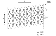
- FIG. 21 is a diagram showing a stent 100E1 that is a modification of the arrangement of the first straight crossing portion 1A and the second straight crossing portion 1B.
- Two first straight crossing portions 1A that are continuous in the circumferential direction C are arranged spirally along the longitudinal axis direction A.
- Two second straight line intersection portions 1B that are continuous in the circumferential direction C are arranged spirally along the longitudinal axis direction A.
- FIG. 21 is a diagram showing a stent 100E1 that is a modification of the arrangement of the first straight crossing portion 1A and the second straight crossing portion 1B.
- FIG. 22 is a diagram showing a stent 100E2 that is a modification of the arrangement of the first straight crossing portion 1A and the second straight crossing portion 1B.
- the three first straight intersection portions 1A that are continuous in the circumferential direction C are arranged spirally along the longitudinal axis direction A.
- three second straight-line intersection portions 1B continuous in the circumferential direction C are arranged spirally along the longitudinal axis direction A.
- FIG. 1A that are continuous in the circumferential direction C are arranged spirally along the longitudinal axis direction A.
- FIG. 23 is a diagram showing a stent 100E3 that is a modification of the arrangement of the first straight crossing portion 1A and the second straight crossing portion 1B.
- the three first straight intersection portions 1A that are continuous in the circumferential direction C are arranged spirally along the longitudinal axis direction A.
- one second straight line intersection portion 1B continuous in the circumferential direction C is arranged spirally along the longitudinal axis direction A.
- FIG. 23 is a diagram showing a stent 100E3 that is a modification of the arrangement of the first straight crossing portion 1A and the second straight crossing portion 1B.
- the three first straight intersection portions 1A that are continuous in the circumferential direction C are arranged spirally along the longitudinal axis direction A.
- one second straight line intersection portion 1B continuous in the circumferential direction C is arranged spirally along the longitudinal axis direction A.
- FIG. 24 is a diagram showing a stent 100E4 that is a modification of the arrangement of the first straight crossing portion 1A and the second straight crossing portion 1B.
- Three or two first straight crossing portions 1A that are continuous in the circumferential direction C are arranged spirally along the longitudinal axis direction A.
- Two second straight line intersection portions 1B that are continuous in the circumferential direction C are arranged spirally along the longitudinal axis direction A.
- the plurality of engaging portions 2 are arranged spirally along the longitudinal axis direction A. As shown in FIG. The distance D in the longitudinal axis direction A between the engaging portions 2 adjacent in the circumferential direction C was substantially the same. However, the arrangement mode of the plurality of engaging portions 2 is not limited to this. 25A and 25B are diagrams showing a modification of the arrangement of the plurality of engaging portions 2. FIG. The distance D in the longitudinal direction A between the engaging portions 2 adjacent to each other in the circumferential direction C does not have to be a constant distance. Moreover, the plurality of engaging portions 2 may be arranged in a spiral shape as a whole. The same is true for the plurality of straight line intersections 1 .
- the plurality of engaging parts 2 includes a fifth engaging part 25, a sixth engaging part 26, and a seventh engaging part 27.
- the sixth engaging portion 26 is adjacent to the fifth engaging portion 25 in the circumferential direction C.
- the seventh engaging portion 27 is adjacent to the sixth engaging portion 26 in the circumferential direction C.
- the positions of the fifth engaging portion 25 and the sixth engaging portion 26 in the longitudinal direction A are substantially the same, and the positions of the sixth engaging portion 26 and the seventh engaging portion 27 in the longitudinal direction A are different.
- the plurality of straight-line intersections 1 includes a third straight-line intersection 13 , a fourth straight-line intersection 14 , and a fifth straight-line intersection 15 .
- the fourth straight intersection portion 14 is adjacent to the third straight intersection portion 13 in the circumferential direction C.
- the fifth straight line intersection portion 15 is adjacent to the fourth straight line intersection portion 14 in the circumferential direction C.
- the positions of the longitudinal axis direction A of the third straight line intersection portion 13 and the fourth straight line intersection portion 14 are substantially the same, and the positions of the longitudinal axis direction A of the fourth straight line intersection portion 14 and the fifth straight line intersection portion 15 are different. .
- the present invention can be applied to stents formed by weaving wires or the like.
- Endoscope system 200 Endoscope 150 Stent delivery system 110 Outer cylinder member 120 Inner cylinder member 130 Chip 100, 100B, 100C, 100D, 100E Stent 1 Straight line intersection 10 Straight line 11 First straight line 12 Second straight line 1A Central straight-line intersection, first straight-line intersection 1B Central straight-line intersection, second straight-line intersection 1C Central straight-line intersection 13 Third straight-line intersection 14 Fourth straight-line intersection 15 Fifth straight-line intersection 2 ) 21 First engaging portion 22 Second engaging portion 23 Third engaging portion 24 Fourth engaging portion 25 Fifth engaging portion 26 Sixth engaging portion 27 Seventh engaging portion 3 Mountain-shaped bent portion (mountain) 31 First mountain 32 Second mountain 33 Third mountain 34 Fourth mountain 4 Valley-shaped bend (valley) 41 First valley 42 Second valley 43 Third valley 44 Fourth valley
Landscapes
- Health & Medical Sciences (AREA)
- Engineering & Computer Science (AREA)
- Biomedical Technology (AREA)
- Heart & Thoracic Surgery (AREA)
- Cardiology (AREA)
- Oral & Maxillofacial Surgery (AREA)
- Transplantation (AREA)
- Vascular Medicine (AREA)
- Life Sciences & Earth Sciences (AREA)
- Animal Behavior & Ethology (AREA)
- General Health & Medical Sciences (AREA)
- Public Health (AREA)
- Veterinary Medicine (AREA)
- Textile Engineering (AREA)
- Manufacturing & Machinery (AREA)
- Media Introduction/Drainage Providing Device (AREA)
Priority Applications (7)
| Application Number | Priority Date | Filing Date | Title |
|---|---|---|---|
| PCT/JP2021/032009 WO2023032052A1 (ja) | 2021-08-31 | 2021-08-31 | ステントおよびステントデリバリーシステム |
| CN202280057995.8A CN117858683A (zh) | 2021-08-31 | 2022-08-29 | 支架和支架输送系统 |
| KR1020247006050A KR20240033279A (ko) | 2021-08-31 | 2022-08-29 | 스텐트 및 스텐트 전달 시스템 |
| EP22864487.8A EP4397283A4 (en) | 2021-08-31 | 2022-08-29 | STENT AND STENT DELIVERY SYSTEM |
| JP2023545554A JP7583950B2 (ja) | 2021-08-31 | 2022-08-29 | ステントおよびステントデリバリーシステム |
| PCT/JP2022/032380 WO2023032905A1 (ja) | 2021-08-31 | 2022-08-29 | ステントおよびステントデリバリーシステム |
| US18/588,630 US20240197502A1 (en) | 2021-08-31 | 2024-02-27 | Stent and stent delivery system |
Applications Claiming Priority (1)
| Application Number | Priority Date | Filing Date | Title |
|---|---|---|---|
| PCT/JP2021/032009 WO2023032052A1 (ja) | 2021-08-31 | 2021-08-31 | ステントおよびステントデリバリーシステム |
Related Child Applications (1)
| Application Number | Title | Priority Date | Filing Date |
|---|---|---|---|
| US18/588,630 Continuation US20240197502A1 (en) | 2021-08-31 | 2024-02-27 | Stent and stent delivery system |
Publications (1)
| Publication Number | Publication Date |
|---|---|
| WO2023032052A1 true WO2023032052A1 (ja) | 2023-03-09 |
Family
ID=85410795
Family Applications (2)
| Application Number | Title | Priority Date | Filing Date |
|---|---|---|---|
| PCT/JP2021/032009 Ceased WO2023032052A1 (ja) | 2021-08-31 | 2021-08-31 | ステントおよびステントデリバリーシステム |
| PCT/JP2022/032380 Ceased WO2023032905A1 (ja) | 2021-08-31 | 2022-08-29 | ステントおよびステントデリバリーシステム |
Family Applications After (1)
| Application Number | Title | Priority Date | Filing Date |
|---|---|---|---|
| PCT/JP2022/032380 Ceased WO2023032905A1 (ja) | 2021-08-31 | 2022-08-29 | ステントおよびステントデリバリーシステム |
Country Status (6)
| Country | Link |
|---|---|
| US (1) | US20240197502A1 (https=) |
| EP (1) | EP4397283A4 (https=) |
| JP (1) | JP7583950B2 (https=) |
| KR (1) | KR20240033279A (https=) |
| CN (1) | CN117858683A (https=) |
| WO (2) | WO2023032052A1 (https=) |
Cited By (1)
| Publication number | Priority date | Publication date | Assignee | Title |
|---|---|---|---|---|
| CN117265770A (zh) * | 2023-09-18 | 2023-12-22 | 江苏唯德康医疗科技有限公司 | 一种支架编织方法及使用该方法编织的支架 |
Families Citing this family (1)
| Publication number | Priority date | Publication date | Assignee | Title |
|---|---|---|---|---|
| CN118436464B (zh) * | 2024-07-08 | 2024-10-15 | 乐普(北京)医疗器械股份有限公司 | 一种主动脉裸支架结构 |
Citations (5)
| Publication number | Priority date | Publication date | Assignee | Title |
|---|---|---|---|---|
| JPH08196642A (ja) * | 1995-01-27 | 1996-08-06 | Terumo Corp | 生体内留置用ステント |
| JP2003102849A (ja) * | 2001-09-28 | 2003-04-08 | Terumo Corp | 生体内留置用ステント |
| JP2004181230A (ja) * | 2002-11-20 | 2004-07-02 | Olympus Corp | ステントデリバリーシステム |
| JP2004344634A (ja) * | 2003-05-23 | 2004-12-09 | Taewoong Medical Co Ltd | 可変状態維持型ステントの製造方法及びこれにより製造された可変状態維持型ステント |
| WO2020194506A1 (ja) * | 2019-03-26 | 2020-10-01 | オリンパス株式会社 | ステント |
Family Cites Families (5)
| Publication number | Priority date | Publication date | Assignee | Title |
|---|---|---|---|---|
| KR100457630B1 (ko) | 2001-04-04 | 2004-11-18 | (주) 태웅메디칼 | 형상기억합금을 이용한 가변상태 유지형 확장기구의제조방법과 이에 의해 제조된 확장기구 |
| WO2011034768A1 (en) * | 2009-09-21 | 2011-03-24 | Boston Scientific Scimed, Inc. | Integrated stent retrieval loop adapted for snare removal and/or optimized purse stringing |
| KR101109709B1 (ko) * | 2009-11-11 | 2012-01-31 | 신경민 | 형상기억합금 와이어를 이용한 스텐트의 제조방법과 이에 의해 제조한 스텐트 및 이를 제조하기 위한 지그의 구조 |
| WO2020049734A1 (ja) * | 2018-09-07 | 2020-03-12 | オリンパス株式会社 | ステント |
| CN113133856B (zh) * | 2021-04-20 | 2022-12-13 | 北京弘海微创科技有限公司 | 一种z型编织支架 |
-
2021
- 2021-08-31 WO PCT/JP2021/032009 patent/WO2023032052A1/ja not_active Ceased
-
2022
- 2022-08-29 CN CN202280057995.8A patent/CN117858683A/zh active Pending
- 2022-08-29 JP JP2023545554A patent/JP7583950B2/ja active Active
- 2022-08-29 EP EP22864487.8A patent/EP4397283A4/en active Pending
- 2022-08-29 WO PCT/JP2022/032380 patent/WO2023032905A1/ja not_active Ceased
- 2022-08-29 KR KR1020247006050A patent/KR20240033279A/ko active Pending
-
2024
- 2024-02-27 US US18/588,630 patent/US20240197502A1/en active Pending
Patent Citations (5)
| Publication number | Priority date | Publication date | Assignee | Title |
|---|---|---|---|---|
| JPH08196642A (ja) * | 1995-01-27 | 1996-08-06 | Terumo Corp | 生体内留置用ステント |
| JP2003102849A (ja) * | 2001-09-28 | 2003-04-08 | Terumo Corp | 生体内留置用ステント |
| JP2004181230A (ja) * | 2002-11-20 | 2004-07-02 | Olympus Corp | ステントデリバリーシステム |
| JP2004344634A (ja) * | 2003-05-23 | 2004-12-09 | Taewoong Medical Co Ltd | 可変状態維持型ステントの製造方法及びこれにより製造された可変状態維持型ステント |
| WO2020194506A1 (ja) * | 2019-03-26 | 2020-10-01 | オリンパス株式会社 | ステント |
Cited By (1)
| Publication number | Priority date | Publication date | Assignee | Title |
|---|---|---|---|---|
| CN117265770A (zh) * | 2023-09-18 | 2023-12-22 | 江苏唯德康医疗科技有限公司 | 一种支架编织方法及使用该方法编织的支架 |
Also Published As
| Publication number | Publication date |
|---|---|
| US20240197502A1 (en) | 2024-06-20 |
| CN117858683A (zh) | 2024-04-09 |
| KR20240033279A (ko) | 2024-03-12 |
| JP7583950B2 (ja) | 2024-11-14 |
| EP4397283A1 (en) | 2024-07-10 |
| EP4397283A4 (en) | 2025-08-13 |
| JPWO2023032905A1 (https=) | 2023-03-09 |
| WO2023032905A1 (ja) | 2023-03-09 |
Similar Documents
| Publication | Publication Date | Title |
|---|---|---|
| US11504221B2 (en) | Biliary stents and methods | |
| KR102487146B1 (ko) | 양성 전립선 비대증(bph) 및 하부 요로 증상(luts)을 치료하기 위한 임플란트 | |
| ES2950893T3 (es) | Dispositivo endoluminal | |
| WO2023032052A1 (ja) | ステントおよびステントデリバリーシステム | |
| US20260013979A1 (en) | Stent device | |
| JP7587049B2 (ja) | ステントデバイスおよびステントデリバリーシステム | |
| JP7612885B2 (ja) | ステントおよびステントデリバリーシステム | |
| US10368974B2 (en) | Gallbladder implants and systems and methods for the delivery thereof | |
| US20230125981A1 (en) | Ureteral stents and methods for using the same | |
| JP7448294B2 (ja) | ステント | |
| KR20220010814A (ko) | 스텐트 | |
| WO2025240721A1 (en) | Pseudo hooked wire stent | |
| CN114053554A (zh) | 一种超声用引流管 |
Legal Events
| Date | Code | Title | Description |
|---|---|---|---|
| 121 | Ep: the epo has been informed by wipo that ep was designated in this application |
Ref document number: 21955942 Country of ref document: EP Kind code of ref document: A1 |
|
| NENP | Non-entry into the national phase |
Ref country code: DE |
|
| 122 | Ep: pct application non-entry in european phase |
Ref document number: 21955942 Country of ref document: EP Kind code of ref document: A1 |
|
| NENP | Non-entry into the national phase |
Ref country code: JP |