WO2023027002A1 - 摺動部品 - Google Patents
摺動部品 Download PDFInfo
- Publication number
- WO2023027002A1 WO2023027002A1 PCT/JP2022/031493 JP2022031493W WO2023027002A1 WO 2023027002 A1 WO2023027002 A1 WO 2023027002A1 JP 2022031493 W JP2022031493 W JP 2022031493W WO 2023027002 A1 WO2023027002 A1 WO 2023027002A1
- Authority
- WO
- WIPO (PCT)
- Prior art keywords
- groove
- space
- fluid
- sliding
- fluid inlet
- Prior art date
- Legal status (The legal status is an assumption and is not a legal conclusion. Google has not performed a legal analysis and makes no representation as to the accuracy of the status listed.)
- Ceased
Links
Images











Classifications
-
- F—MECHANICAL ENGINEERING; LIGHTING; HEATING; WEAPONS; BLASTING
- F16—ENGINEERING ELEMENTS AND UNITS; GENERAL MEASURES FOR PRODUCING AND MAINTAINING EFFECTIVE FUNCTIONING OF MACHINES OR INSTALLATIONS; THERMAL INSULATION IN GENERAL
- F16J—PISTONS; CYLINDERS; SEALINGS
- F16J15/00—Sealings
- F16J15/16—Sealings between relatively-moving surfaces
- F16J15/34—Sealings between relatively-moving surfaces with slip-ring pressed against a more or less radial face on one member
- F16J15/3404—Sealings between relatively-moving surfaces with slip-ring pressed against a more or less radial face on one member and characterised by parts or details relating to lubrication, cooling or venting of the seal
- F16J15/3408—Sealings between relatively-moving surfaces with slip-ring pressed against a more or less radial face on one member and characterised by parts or details relating to lubrication, cooling or venting of the seal at least one ring having an uneven slipping surface
-
- F—MECHANICAL ENGINEERING; LIGHTING; HEATING; WEAPONS; BLASTING
- F16—ENGINEERING ELEMENTS AND UNITS; GENERAL MEASURES FOR PRODUCING AND MAINTAINING EFFECTIVE FUNCTIONING OF MACHINES OR INSTALLATIONS; THERMAL INSULATION IN GENERAL
- F16C—SHAFTS; FLEXIBLE SHAFTS; ELEMENTS OR CRANKSHAFT MECHANISMS; ROTARY BODIES OTHER THAN GEARING ELEMENTS; BEARINGS
- F16C33/00—Parts of bearings; Special methods for making bearings or parts thereof
- F16C33/02—Parts of sliding-contact bearings
- F16C33/04—Brasses; Bushes; Linings
- F16C33/06—Sliding surface mainly made of metal
- F16C33/10—Construction relative to lubrication
-
- F—MECHANICAL ENGINEERING; LIGHTING; HEATING; WEAPONS; BLASTING
- F16—ENGINEERING ELEMENTS AND UNITS; GENERAL MEASURES FOR PRODUCING AND MAINTAINING EFFECTIVE FUNCTIONING OF MACHINES OR INSTALLATIONS; THERMAL INSULATION IN GENERAL
- F16C—SHAFTS; FLEXIBLE SHAFTS; ELEMENTS OR CRANKSHAFT MECHANISMS; ROTARY BODIES OTHER THAN GEARING ELEMENTS; BEARINGS
- F16C17/00—Sliding-contact bearings for exclusively rotary movement
- F16C17/04—Sliding-contact bearings for exclusively rotary movement for axial load only
- F16C17/045—Sliding-contact bearings for exclusively rotary movement for axial load only with grooves in the bearing surface to generate hydrodynamic pressure, e.g. spiral groove thrust bearings
-
- F—MECHANICAL ENGINEERING; LIGHTING; HEATING; WEAPONS; BLASTING
- F16—ENGINEERING ELEMENTS AND UNITS; GENERAL MEASURES FOR PRODUCING AND MAINTAINING EFFECTIVE FUNCTIONING OF MACHINES OR INSTALLATIONS; THERMAL INSULATION IN GENERAL
- F16C—SHAFTS; FLEXIBLE SHAFTS; ELEMENTS OR CRANKSHAFT MECHANISMS; ROTARY BODIES OTHER THAN GEARING ELEMENTS; BEARINGS
- F16C33/00—Parts of bearings; Special methods for making bearings or parts thereof
- F16C33/02—Parts of sliding-contact bearings
- F16C33/04—Brasses; Bushes; Linings
- F16C33/06—Sliding surface mainly made of metal
- F16C33/10—Construction relative to lubrication
- F16C33/1025—Construction relative to lubrication with liquid, e.g. oil, as lubricant
- F16C33/106—Details of distribution or circulation inside the bearings, e.g. details of the bearing surfaces to affect flow or pressure of the liquid
- F16C33/1065—Grooves on a bearing surface for distributing or collecting the liquid
-
- F—MECHANICAL ENGINEERING; LIGHTING; HEATING; WEAPONS; BLASTING
- F16—ENGINEERING ELEMENTS AND UNITS; GENERAL MEASURES FOR PRODUCING AND MAINTAINING EFFECTIVE FUNCTIONING OF MACHINES OR INSTALLATIONS; THERMAL INSULATION IN GENERAL
- F16C—SHAFTS; FLEXIBLE SHAFTS; ELEMENTS OR CRANKSHAFT MECHANISMS; ROTARY BODIES OTHER THAN GEARING ELEMENTS; BEARINGS
- F16C33/00—Parts of bearings; Special methods for making bearings or parts thereof
- F16C33/02—Parts of sliding-contact bearings
- F16C33/04—Brasses; Bushes; Linings
- F16C33/06—Sliding surface mainly made of metal
- F16C33/10—Construction relative to lubrication
- F16C33/1025—Construction relative to lubrication with liquid, e.g. oil, as lubricant
- F16C33/106—Details of distribution or circulation inside the bearings, e.g. details of the bearing surfaces to affect flow or pressure of the liquid
- F16C33/107—Grooves for generating pressure
-
- F—MECHANICAL ENGINEERING; LIGHTING; HEATING; WEAPONS; BLASTING
- F16—ENGINEERING ELEMENTS AND UNITS; GENERAL MEASURES FOR PRODUCING AND MAINTAINING EFFECTIVE FUNCTIONING OF MACHINES OR INSTALLATIONS; THERMAL INSULATION IN GENERAL
- F16C—SHAFTS; FLEXIBLE SHAFTS; ELEMENTS OR CRANKSHAFT MECHANISMS; ROTARY BODIES OTHER THAN GEARING ELEMENTS; BEARINGS
- F16C33/00—Parts of bearings; Special methods for making bearings or parts thereof
- F16C33/72—Sealings
- F16C33/74—Sealings of sliding-contact bearings
-
- F—MECHANICAL ENGINEERING; LIGHTING; HEATING; WEAPONS; BLASTING
- F16—ENGINEERING ELEMENTS AND UNITS; GENERAL MEASURES FOR PRODUCING AND MAINTAINING EFFECTIVE FUNCTIONING OF MACHINES OR INSTALLATIONS; THERMAL INSULATION IN GENERAL
- F16J—PISTONS; CYLINDERS; SEALINGS
- F16J15/00—Sealings
- F16J15/16—Sealings between relatively-moving surfaces
- F16J15/34—Sealings between relatively-moving surfaces with slip-ring pressed against a more or less radial face on one member
- F16J15/3404—Sealings between relatively-moving surfaces with slip-ring pressed against a more or less radial face on one member and characterised by parts or details relating to lubrication, cooling or venting of the seal
- F16J15/3408—Sealings between relatively-moving surfaces with slip-ring pressed against a more or less radial face on one member and characterised by parts or details relating to lubrication, cooling or venting of the seal at least one ring having an uneven slipping surface
- F16J15/3412—Sealings between relatively-moving surfaces with slip-ring pressed against a more or less radial face on one member and characterised by parts or details relating to lubrication, cooling or venting of the seal at least one ring having an uneven slipping surface with cavities
Definitions
- the present invention relates to sliding parts used for shaft seals and bearings of rotating machines.
- a mechanical seal consisting of a pair of annular sliding rings that rotate relative to each other and whose sliding surfaces slide against each other is known as a sliding part that prevents leakage of the sealed fluid around the rotating shaft in a rotating machine.
- a mechanical seal consisting of a pair of annular sliding rings that rotate relative to each other and whose sliding surfaces slide against each other is known as a sliding part that prevents leakage of the sealed fluid around the rotating shaft in a rotating machine.
- the mechanical seal disclosed in Patent Document 1 has, on the sliding surface of one of the sliding rings, a fluid inlet/outlet groove that extends in the radial direction and communicates with the sealed liquid side but does not communicate with the leak side, and the fluid inlet/outlet groove.
- a plurality of positive pressure generating mechanisms are provided in the circumferential direction via lands. According to this, during the relative rotation of the slide ring, the sealed fluid is introduced into the positive pressure generating groove through the fluid lead-in/out groove, and the sealed fluid is applied to the wall portion of the end portion of the positive pressure generating groove in the relative rotation direction. Concentrated positive pressure is generated to separate the sliding surfaces, and a fluid film of the sealed fluid is formed on the sliding surfaces, thereby improving lubricity and realizing low friction.
- the sealed fluid in the positive pressure generation groove moves toward the end in the relative rotation direction following the relative rotational sliding of the pair of slide rings, thereby The sealed fluid is continuously supplied into the positive pressure generating groove from the space on the sealing fluid side through the fluid inlet/outlet groove.
- the corner formed by the bottom surface of the fluid inlet/outlet groove and the peripheral surface of the slide ring on the side of the sealed fluid is formed at a right angle.
- the present invention has been made with a focus on such problems, and an object of the present invention is to provide a sliding component in which a fluid can be easily introduced or discharged between a groove and a communicating space.
- the sliding component of the present invention is A sliding part in which a pair of sliding rings rotate relative to each other and partition a sealed fluid space and a leakage space,
- the sliding surface of one of the sliding rings is provided with a groove that opens to at least one of the space on the sealed fluid side and the leakage side,
- a groove is formed between the groove of the one slide ring and the other slide ring.
- An inclined surface is provided that communicates with the fluid space and widens toward the space on the side where the groove is provided.
- the fluid flows from the space on the side where the groove is provided to the fluid space, or from the fluid space along the inclined surface widened toward the space on the side where the groove is provided. Since it smoothly moves to the space on the side where the groove is provided, the fluid is easily introduced or discharged between the fluid space and the space on the side where the groove is provided.
- the groove includes a fluid inlet/outlet groove that opens into a space on the side where the groove is provided, and a dynamic pressure generating groove that extends in the circumferential direction and communicates with the fluid inlet/outlet groove,
- the fluid inlet/outlet groove may be deeper than the dynamic pressure generating groove. According to this, since the fluid can be sufficiently retained in the fluid lead-in/out groove, poor lubrication of the dynamic pressure generating groove can be prevented.
- the groove includes a fluid inlet/outlet groove that opens into a space on the side where the groove is provided, and a dynamic pressure generating groove that extends in the circumferential direction and communicates with the fluid inlet/outlet groove,
- the fluid inlet/outlet groove and the dynamic pressure generating groove may have the same depth. According to this, the fluid can flow smoothly between the fluid inlet/outlet groove and the dynamic pressure generating groove.
- the inclined surface may be provided on the one sliding ring. According to this, regardless of the sliding state of the pair of sliding rings, the state of communication between the inclined surface and the fluid space can always be maintained constant.
- the bottom surface of the fluid inlet/outlet groove and the inclined surface may form an obtuse angle. According to this, a vortex is less likely to occur at the boundary between the inclined surface and the bottom surface of the fluid inlet/outlet groove.
- An inclined groove is formed in the one sliding ring by the inclined surface and side surfaces rising from both circumferential ends of the inclined surface, An edge portion of the one or the other slide ring on the side of the space where the groove is provided is formed with a widening surface that is widened toward the space on the side where the groove is provided. cage, A communication space defined by the expanding surface and extending in the circumferential direction may communicate with the inclined groove. According to this, the sealed fluid can be introduced into or discharged from the inclined groove from the radial direction and the circumferential direction.
- the fluid inlet/outlet groove communicates with the space on the inner diameter side,
- the position of the outermost diameter of the dynamic pressure generating groove may be located on the outer diameter side of the position of the outermost diameter of the fluid inlet/outlet groove. According to this, it is possible to ensure a large communication area between the dynamic pressure generating groove and the fluid inlet/outlet groove.
- the fluid inlet/outlet groove communicates with the space on the outer diameter side,
- the position of the innermost diameter of the dynamic pressure generating groove may be located on the inner diameter side of the position of the innermost diameter of the fluid inlet/outlet groove. According to this, it is possible to ensure a large communication area between the dynamic pressure generating groove and the fluid inlet/outlet groove.
- the dynamic pressure generating grooves may be provided on both circumferential sides of the fluid lead-in/out groove, and the dynamic pressure generating grooves may communicate with each other. According to this, since the dynamic pressure generating grooves on both sides in the circumferential direction of the fluid inlet/outlet groove communicate with each other, cavitation generated in the communicating portion and its surroundings makes it difficult for the fluid to leak to the other space side.
- the fluid inlet/outlet groove communicates with the space on the side of the fluid to be sealed, and the sliding surface of the one or the other sliding ring communicates with the space on the side of the fluid to be sealed.
- a spiral groove that does not communicate with may be provided. According to this, when the pair of sliding rings rotates relative to each other, the sliding surfaces are separated from each other by the dynamic pressure generating groove and the spiral groove, and the sealed fluid and the leak side fluid form a fluid film between the sliding surfaces. Since it can be formed, the lubricity between the sliding surfaces is improved.
- the edge of the one slide ring on the leakage side communicates with another fluid space formed between the spiral groove and the other slide ring and expands toward the space on the leakage side.
- the sealed fluid may be liquid, and the leak side fluid may be gas. According to this, when the pair of sliding rings rotates at a low speed, the liquid lubricates the sliding surfaces, and when the pair rotates at a high speed, the gas can lubricate the sliding surfaces.
- the groove is a strip-shaped open groove whose circumferential length is longer than its radial length, and at least a part of the open groove is open to the space on the side where the groove is provided along the circumferential direction.
- An opening may be formed. According to this, the opening formed in the opening groove is open along the circumferential direction, and the fluid in the space on the side where the groove is provided is taken into the groove from the opening, so that the sliding is prevented. Even if the relative rotational speed of the parts increases, a large amount of fluid in the space on the side where the groove is provided from the opening can be taken into the groove, and a desired positive pressure can be generated between the sliding surfaces.
- the opening groove includes a first groove portion formed with the opening portion and extending in the circumferential direction, and a second groove portion extending radially from the downstream end portion of the first groove portion and having the end portion closed. may have. According to this, the fluid in the space on the side where the groove is provided can be introduced into the space on the other space side, which is more distant from the space on the side where the groove is provided. It is possible to suppress the movement of the side on which the groove is provided to the space side.
- the second groove portion may include an inclined portion extending radially and an extending portion extending circumferentially from the inclined portion. According to this, the inclined portion can improve the efficiency of introducing the fluid into the space on the side where the groove is provided into the second groove portion, and the extension portion can displace the fluid in the radial direction more than the first groove portion. A positive pressure can be generated at the
- the opening groove may be formed symmetrically with respect to a line extending in the radial direction. According to this, it can be used regardless of the relative rotation direction of the sliding parts.
- FIG. 1 is a longitudinal sectional view showing an example of a mechanical seal in Example 1 of the present invention
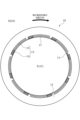
- FIG. FIG. 4 is a view of the sliding surface of the stationary seal ring in Example 1 as seen from the axial direction
- 4 is an enlarged view of the sliding surface of the stationary seal ring in Example 1 as seen from the axial direction
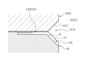
- FIG. (a) is a cross-sectional view taken along the line AA in FIG. 3
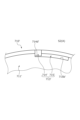
- (b) is a view of the fluid inlet/outlet space and its surroundings as seen from the inner diameter side.
- FIG. 8 is an enlarged view of the sliding surface of the stationary seal ring in Example 2 of the present invention, viewed from the axial direction
- FIG. 6 is a cross-sectional view taken along the line A'-A' of FIG.
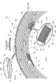
- FIG. 11 is a view of the sliding surface of the stationary seal ring in Example 3 of the present invention as seen from the axial direction;
- FIG. 11 is an enlarged view of the sliding surface of the stationary seal ring in Example 3 of the present invention as seen from the axial direction;
- FIG. 9 is a cross-sectional view taken along the line BB of FIG. 8; It is the figure which looked at the axial direction which shows the modification of the stationary seal ring in Example 3 of this invention.
- FIG. 11 is an enlarged view of the sliding surface of the stationary seal ring in Example 4 of the present invention as seen from the axial direction;
- FIG. 12 is an enlarged view of the sliding surface of the stationary seal ring in Example 5 of the present invention, viewed from the axial direction;
- FIG. 12 is an enlarged view of the sliding surface of the stationary seal ring in Example 6 of the present invention, viewed from the axial direction; (a) is an enlarged view of the sliding surface of the stationary seal ring in Example 7 of the present invention as seen from the axial direction, and (b) is a cross-sectional view of the same along CC.
- FIG. 10 is a cross-sectional view of a fluid inlet/outlet groove in Example 8 of the present invention
- FIG. 11 is a cross-sectional view of a fluid inlet/outlet groove in Example 9 of the present invention
- FIG. 10 is a cross-sectional view of a fluid inlet/outlet groove in Example 10 of the present invention;
- FIG. 11 is a cross-sectional view of a fluid inlet/outlet groove in Example 11 of the present invention
- FIG. 12 is a cross-sectional view of a fluid inlet/outlet groove in Example 12 of the present invention
- FIG. 20 is a cross-sectional view of a fluid inlet/outlet groove in Example 13 of the present invention
- FIG. 20 is a cross-sectional view of a fluid inlet/outlet groove in Example 14 of the present invention
- (a) is an enlarged view of the dynamic pressure generating groove in Example 15 of the present invention as seen from the axial direction
- (b) is a GG sectional view of (a)
- (c) is a HH sectional view of the same. .
- FIG. 20 is an enlarged view of a dynamic pressure generating groove in Example 16 of the present invention as seen from the axial direction;
- (a) is an enlarged view of a dynamic pressure generating mechanism in Embodiment 17 of the present invention as seen from the axial direction, and
- (b) is a cross-sectional view taken along line EE of (a).
- FIG. 21 is an enlarged view of a dynamic pressure generating mechanism in Example 18 of the present invention, viewed from the axial direction;
- FIG. 20 is an enlarged view of the dynamic pressure generating mechanism in Example 19 of the present invention as seen from the axial direction;
- (a) is an enlarged view of the sliding surface of the stationary seal ring in Example 20 of the present invention as seen from the axial direction, and
- (b) is a JJ cross-sectional view of (a).
- (a) is an enlarged view of the sliding surface of the stationary seal ring in Example 21 of the present invention as seen from the axial direction, and (b) is a KK cross-sectional view of (a).
- FIG. 10 is a view of the sliding surface of the stationary seal ring in Example 22 of the present invention as seen from the axial direction;
- FIG. 14 is an enlarged view of grooves in Example 22 of the present invention as seen from the axial direction;
- FIG. 11 is an enlarged view of grooves in Example 23 of the present invention as seen from the axial direction;
- FIG. 24 is a view of the sliding surface of the stationary seal ring in Example 24 of the present invention as seen from the axial direction;
- FIG. 14 is an enlarged view of grooves in Example 25 of the present invention as seen from the axial direction;
- FIG. 14 is an enlarged view of grooves in Example 26 of the present invention as seen from the axial direction;
- FIG. 1 A mechanical seal as a sliding component according to Example 1 will be described with reference to FIGS. 1 to 4.
- FIG. the sealed fluid F exists in the inner space S1 of the mechanical seal, and the atmosphere A exists in the outer space S2. side (high pressure side) and the outer diameter side as the leakage side (low pressure side).
- side high pressure side
- outer diameter side as the leakage side
- dots may be attached to grooves formed on the sliding surface in the drawings.
- the mechanical seal shown in FIG. 1 is of the outside type in which the sealed fluid F in the inner space S1 that tends to leak from the inner diameter side of the sliding surface toward the outer diameter side is sealed, and the outer space S2 communicates with the atmosphere A. It is.
- the sealed fluid F is a high-pressure liquid
- the atmosphere A is a gas with a pressure lower than that of the sealed fluid F.
- the mechanical seal is mainly composed of a rotating seal ring 20 as the other sliding ring and a stationary sealing ring 10 as one sliding ring.
- the rotary seal ring 20 has an annular shape and is provided on the rotary shaft 1 through the sleeve 2 so as to be rotatable together with the rotary shaft 1 .
- the stationary seal ring 10 has an annular shape and is provided in a non-rotatable and axially movable state on a seal cover 5 fixed to a housing 4 of a device to which it is attached.
- the stationary seal ring 10 is urged in the axial direction by the elastic member 7, so that the sliding surface 11 of the stationary seal ring 10 and the sliding surface 21 of the rotary seal ring 20 closely slide against each other.
- the sliding surface 21 of the rotary seal ring 20 is a flat surface, and this flat surface is not provided with recesses such as grooves.
- the stationary seal ring 10 and the rotary seal ring 20 are typically formed of a combination of SiC (hard material) or SiC (hard material) and carbon (soft material). Any material that is used as a sliding material for mechanical seals can be applied.
- SiC include sintered bodies using boron, aluminum, carbon, etc. as sintering aids, and materials composed of two or more phases with different components and compositions, such as SiC and SiC in which graphite particles are dispersed.
- Metal materials, resin materials, surface modification materials (coating materials), composite materials, etc. are also applicable in addition to the sliding materials described above.
- the rotating seal ring 20 which is the mating seal ring, slides clockwise relative to the stationary seal ring 10 as indicated by the solid line arrow.
- a plurality of dynamic pressure generating mechanisms 13 are provided on the sliding surface 11 of the stationary seal ring 10 .
- the dynamic pressure generating mechanisms 13 are evenly arranged in the circumferential direction on the inner diameter side of the sliding surface 11 (eight in this embodiment).
- the portion of the sliding surface 11 other than the dynamic pressure generating mechanism 13 is a land 12 that forms a flat surface arranged on the same plane.
- the flat surface of the land 12 functions as a sliding surface that substantially slides against the sliding surface 21 of the rotary seal ring 20 .
- a plurality of inclined grooves 61 (see FIG. 4) and an enlarged surface 17 are provided on the edge 10e of the stationary seal ring 10 on the inner space S1 side.
- a plurality of inclined grooves 61 and an enlarged surface 17 are provided on the edge portion 10e of the stationary seal ring 10 on the inner diameter side of the sliding surface 11.
- the widening surface 17 is disposed between the inclined grooves 61 adjacent to each other in the circumferential direction at the edge portion 10e on the inner diameter side of the sliding surface 11 (eight in this embodiment).
- the expanding surface 17 has a so-called chamfered shape.
- the inclined groove 61 extends continuously with a later-described fluid inlet/outlet groove 14 of the dynamic pressure generating mechanism 13 .
- the expanding surface 17 is a tapered surface that gradually deepens from the flat surface of the land 12 toward the inner peripheral surface 10g of the stationary seal ring 10 (see FIG. 4).
- the expansion surface 17 may have irregularities, but is preferably flat.
- the dynamic pressure generating mechanism 13 is composed of a fluid inlet/outlet groove 14 as a fluid inlet/outlet groove and a Rayleigh step 15 as a dynamic pressure generating groove.
- the fluid inlet/outlet groove 14 extends radially so as to communicate with the inner space S1 and not communicate with the outer space S2.
- the Rayleigh step 15 extends circumferentially concentrically with the stationary seal ring 10 in a clockwise direction from the outer diameter side of the fluid inlet/outlet groove 14 .
- the depth D1 of the fluid inlet/outlet groove 14 is formed deeper than the depth D2 of the Rayleigh step 15 (D1>D2).
- the Rayleigh step 15 is not limited to extending in an arc shape, and may extend in a straight line.
- the Rayleigh step 15 is not limited to being provided concentrically with the stationary seal ring 10, and may be inclined in the circumferential direction.
- the fluid inlet/outlet groove 14 is composed of a bottom surface 14a, side surfaces 14b and 14c, and an outer diameter side end surface 14d.
- the bottom surface 14 a extends radially parallel to the flat surface of the land 12 .
- the side surfaces 14b and 14c rise from both circumferential edges of the bottom surface 14a.
- the outer diameter side end surface 14d rises from the outer diameter end of the bottom surface 14a and is orthogonally connected to the side surfaces 14b and 14c.
- An opening 14A communicating with the Rayleigh step 15 is formed in the side surface 14b.
- An opening 14B communicating with the inner space S1 is formed on the inner diameter side of the fluid lead-in/out groove 14. As shown in FIG.
- a sloped surface 6 extending radially inward is continuously provided on the radially inner edge 14g of the bottom surface 14a of the fluid inlet/outlet groove 14 . More specifically, the inclined surface 6 is formed so that its depth increases from the inner diameter side edge 14g of the bottom surface 14a of the fluid lead-in/out groove 14 toward the inner peripheral surface 10g of the stationary seal ring 10, in other words, the rotary seal ring 20. slantly extending linearly so that the distance from the sliding surface 21 of the . Also, the inclined surface 6 is parallel to the expanding surface 17 .
- the bottom surface 14a of the fluid inlet/outlet groove 14 and the inclined surface 6 form an obtuse angle.
- the bottom surface 14a of the fluid inlet/outlet groove 14 and the inclined surface 6 form an obtuse angle, but the present invention is not limited to this. may Also, a small step may be formed in a portion near the boundary between the bottom surface 14 a and the inclined surface 6 .
- the inclined surface 6 continues to the first fluid inlet/outlet space S10 as a fluid space formed between the fluid inlet/outlet groove 14 and the sliding surface 21 of the rotary seal ring 20, and faces toward the inner space S1.
- the distance away from the rotary seal ring 20 may be simply referred to as the "depth”
- the direction may be referred to as the "depth direction”).
- the inclined surface 6 is preferably a flat surface.
- the inclined surface 6 and the expanded surface 17 are connected by side surfaces 19b and 19c rising from both circumferential direction edges of the inclined surface 6 .
- the side surfaces 19b and 19c are continuous with the side surfaces 14b and 14c of the fluid inlet/outlet groove 14 in the radial direction.
- an inclined groove 61 surrounded by the inclined surface 6 and the side surfaces 19b and 19c is formed in the edge 10e of the stationary seal ring 10 on the inner space S1 side.
- the first fluid inlet/outlet space S10 communicates with the inner space S1 through an inclined groove 61 .
- a communication space S11 is formed between the enlarged surface 17 and the inner diameter side end of the rotary seal ring 20. As shown in FIG.
- FIG. 3 The flow of the sealed fluid F and the air A in FIG. 3 is schematically shown without specifying the relative rotational speed of the rotary seal ring 20 .
- the sealed fluid F flows into the fluid inlet/outlet groove 14 . Since the stationary seal ring 10 is urged toward the rotary seal ring 20 by the elastic member 7, the sliding surfaces 11 and 21 are in contact with each other, and the fluid F to be sealed between the sliding surfaces 11 and 21 is kept in contact with each other. There is almost no amount of leaking into the outer space S2.
- the sealed fluid F in the Rayleigh step 15 shears against the sliding surface 21, causing the rotary seal ring 20 to move.
- the sealed fluid F in the inner space S1 is drawn into the fluid lead-in/out groove 14 through the inclined groove 61 . That is, within the fluid inlet/outlet groove 14, the sealed fluid F moves from the fluid inlet/outlet groove 14 toward the downstream end portion 15A in the relative rotation direction of the Rayleigh step 15 as indicated by the arrow H1.
- the pressure of the sealed fluid F that has moved toward the end 15A of the Rayleigh step 15 is increased at the end 15A of the Rayleigh step 15 and its vicinity. That is, a positive pressure is generated at the end 15A of the Rayleigh step 15 and its vicinity.
- the sliding surfaces 11 and 21 are slightly separated from each other due to the positive pressure generated at the end 15A of the Rayleigh step 15 and its vicinity.
- the sealed fluid F in the dynamic pressure generating mechanism 13 mainly shown by the arrow H2 flows.
- lubricity is improved even during low-speed rotation, and wear between the sliding surfaces 11 and 21 can be suppressed. Since the floating distance between the sliding surfaces 11 and 21 is small, the amount of the sealed fluid F that leaks into the outer space S2 is small.
- the depth D1 of the fluid lead-in/out groove 14 is formed deeper than the depth D2 of the Rayleigh step 15, so that the fluid lead-in/out groove 14 can hold a large amount of the sealed fluid F.
- the inner diameter side of the bottom surface 14a of the fluid inlet/outlet groove 14 is continuously provided with an inclined surface 6 that is inclined so as to expand in the depth direction.
- the sealed fluid F flowing radially from a position deeper than the fluid inlet/outlet groove 14 is smoothly supplied to the first fluid inlet/outlet space S10 along the inclined surface 6.
- the sealed fluid F is easily introduced into S10, and reduction of the sealed fluid F in the first fluid inlet/outlet space S10 can be suppressed.
- a vortex is less likely to occur between the bottom surface 14 a of the fluid inlet/outlet groove 14 and the inclined surface 6 . That is, it is possible to avoid poor lubrication between the sliding surfaces 11 and 21 during low-speed rotation.
- the inclined surface 6 is provided continuously with the bottom surface 14 a of the fluid inlet/outlet groove 14 . That is, since the inclined surface 6 is provided on the stationary seal ring 10 provided with the fluid inlet/outlet groove 14, the inclined surface 6 can be inclined regardless of the relative positions of the stationary seal ring 10 and the rotary seal ring 20 in the circumferential and axial directions. A constant state of communication between the surface 6 and the fluid inlet/outlet groove 14 can be maintained.
- the inclined grooves 61 are connected in the radial direction (arrow in FIG. 3). H1) and the circumferential direction (see arrow H3 in FIG. 3).
- the static seal ring 10 can be easily manufactured because the dynamic pressure generating mechanism 13 can be processed by a laser or the like after the expanding surface 17 is formed in an annular shape on the stationary seal ring 10 by polishing or the like.
- the inclined groove 61 has side surfaces 19b and 19c, the sealed fluid F introduced into the inclined groove 61 is radially guided toward the first fluid inlet/outlet space S10.
- the expanding surface 17 extends between the adjacent inclined grooves 61 in the circumferential direction, but the expanding surface may be interrupted in the circumferential direction.
- the mechanical seal of Example 2 has the same configuration as the mechanical seal of Example 1, and the rotating direction of the rotary seal ring 20 is different. As shown in FIG. 5, the rotary seal ring 20 slides counterclockwise relative to the stationary seal ring 10 as indicated by the solid line arrow.
- the sealed fluid F in the Rayleigh step 15 shears against the sliding surface 21, causing the rotary seal ring 20 to move. It follows the direction of rotation. As a result, the sealed fluid F in the Rayleigh step 15 moves to the fluid inlet/outlet groove 14 as indicated by the arrow H1' and is discharged into the inner space S1. Also, part of the sealed fluid F in the fluid inlet/outlet groove 14 is discharged to the expanded surface 17 on the downstream side of the relative rotation as indicated by the arrow H3'.
- the inside of the Rayleigh step 15 becomes relatively negative pressure.
- the pressure is the lowest at the end 15A of the Rayleigh step 15 . Therefore, the sealed fluid F between the sliding surfaces 11 and 21 in the vicinity of the end portion 15A can be recovered in the Rayleigh step 15, and the sliding surfaces 11 and 21 can be brought close to each other by the force of the negative pressure. can.
- part of the sealed fluid F that has moved from the Rayleigh step 15 to the fluid inlet/outlet groove 14 is discharged along the bottom surface 14a into the inner space S1, and the other part is discharged along the inclined surface 14a. 6 is smoothly discharged into the inner space S1.
- a plurality of dynamic pressure generating mechanisms 13 and a plurality of spiral grooves 16 are provided on the sliding surface 11 of the stationary seal ring 10' of the third embodiment.
- the dynamic pressure generating mechanism 13 has the same configuration as the mechanical seal of the first embodiment.
- the spiral grooves 16 are evenly arranged in the circumferential direction (48 in this embodiment) on the outer diameter side of the sliding surface 11 .
- a plurality of inclined grooves 81 (see FIG. 9) and an enlarged surface 18 are provided on the edge 10e' of the stationary seal ring 10' on the side of the outer space S2.
- a plurality of inclined grooves 81 and an enlarged surface 18 are provided on the edge portion 10e' of the stationary seal ring 10' on the outer diameter side of the sliding surface 11.
- the expanding surfaces 18 are arranged (48 in this embodiment) between the adjacent inclined grooves 81 in the circumferential direction at the edge portion 10 e ′ on the outer diameter side of the sliding surface 11 . Further, the expanding surface 18 has a so-called chamfered shape. Also, the inclined groove 81 extends continuously with the spiral groove 16 .
- the portion of the sliding surface 11 other than the dynamic pressure generating mechanism 13 and the spiral groove 16 is a land 12 forming a flat surface.
- the land 12 includes a land portion between the dynamic pressure generating mechanisms 13 adjacent in the circumferential direction, a land portion between the spiral grooves 16 adjacent in the circumferential direction, and the dynamic pressure generating mechanisms 13 spaced apart in the radial direction. and land portions between the spiral grooves 16 , and these land portions are arranged in the same plane to form the flat surface of the land 12 .
- the expanding surface 18 is a tapered surface that is gradually deepened from the flat surface of the land 12 toward the outer peripheral surface of the stationary seal ring 10' (see FIG. 9). Although the expansion surface 18 may have unevenness, it is preferably a flat surface.
- the spiral groove 16 extends in an arc shape from the outer diameter side to the inner diameter side while being inclined with a clockwise component.
- the spiral groove 16 communicates with the outer space S2 and does not communicate with the inner space S1.
- the spiral groove 16 is formed with a constant depth in the circumferential direction.
- the spiral groove 16 is not limited to extending in an arc while being inclined, and may extend in a straight line.
- the spiral groove 16 is composed of a bottom surface 16a, side surfaces 16b and 16c, and an end surface 16d.
- the bottom surface 16 a extends radially parallel to the flat surface of the land 12 .
- the side surfaces 16b and 16c rise from both circumferential edges of the bottom surface 16a.
- the end surface 16d connects the inner diameter ends of the bottom surface 16a and the side surfaces 16b and 16c.
- An opening 16A communicating with the outer space S2 is formed on the outer diameter side of the spiral groove 16. As shown in FIG.
- Another inclined surface 8 extending radially in parallel with the widening surface 18 is continuously provided on the radially outer edge of the bottom surface 16 a of the spiral groove 16 . More specifically, the other inclined surface 8 extends straight from the outer edge 16g of the bottom surface 16a of the spiral groove 16 toward the outer peripheral surface of the stationary seal ring 10' while being inclined in the depth direction. The bottom surface 16a of the spiral groove 16 and the inclined surface 8 form an obtuse angle.
- the inclined surface 8 continues to the second fluid inlet/outlet space S12 as another fluid space formed between the spiral groove 16 and the sliding surface 21 of the rotary seal ring 20, and faces toward the outer space S2. are expanding.
- the inclined surface 8 may have unevenness or a curved surface, it is preferably a flat surface.
- the inclined surface 8 and the expanded surface 18 are connected by side surfaces 9b and 9c that rise from both circumferential ends of the inclined surface 8 and are radially continuous with the side surfaces 16b and 16c.
- an inclined groove 81 surrounded by the inclined surface 8 and the side surfaces 9b and 9c is formed in the edge 10e' of the stationary seal ring 10' on the side of the outer space S2.
- the spiral groove 16 communicates with the outer space S2 through the inclined groove 61 .
- the inclined grooves 81 adjacent in the circumferential direction communicate with each other through the communication space S13.
- a communication space S13 is formed between the enlarged surface 18 and the rotary seal ring 20. As shown in FIG.
- FIG.3 and FIG.4 is also referred and demonstrated.
- the flow of the sealed fluid F and the air A in FIG. 8 is schematically shown without specifying the relative rotational speed of the rotary seal ring 20 .
- 4 shows the relative rotation of the stationary seal ring 10 and the rotary seal ring 20 at low speed
- FIG. 9 shows the relative rotation of the stationary seal ring 10 and the rotary seal ring 20 at high speed.
- the sealed fluid F flows into the fluid inlet/outlet groove 14 . Since the stationary seal ring 10 is urged toward the rotary seal ring 20 by the elastic member 7, the sliding surfaces 11 and 21 are in contact with each other, and the fluid F to be sealed between the sliding surfaces 11 and 21 is kept in contact with each other. There is almost no amount of leaking into the outer space S2.
- the atmosphere A does not become sufficiently dense in the spiral groove 16 and high positive pressure is not generated.
- the force due to the generated positive pressure is relatively smaller than the force due to the positive pressure generated at the end 15A of the Rayleigh step 15 and its vicinity. Therefore, when the rotary seal ring 20 rotates at a low speed, the positive pressure generated at the end 15A of the Rayleigh step 15 and its vicinity mainly acts to separate the sliding surfaces 11 and 21 from each other.
- Atmosphere A in space S2 is drawn into spiral groove 16 . That is, in the spiral groove 16, a large amount of air A moves from the outer diameter side opening 16A toward the inner diameter side end portion 16B as indicated by the arrow L1.
- the atmosphere A that has moved toward the inner diameter side end 16B of the spiral groove 16 is increased in pressure at the inner diameter side end 16B of the spiral groove 16 and its vicinity. That is, a positive pressure is generated at the end portion 16B on the inner diameter side of the spiral groove 16 and its vicinity.
- the atmosphere A in the spiral groove 16 indicated by the arrow L2 acts to push back the sealed fluid F in the vicinity of the end portion 16B on the inner diameter side of the spiral groove 16 toward the inner space S1. A small amount of the sealed fluid F leaks out.
- the mechanical seal of this embodiment is designed such that the positive pressure generating capability of the entire spiral groove 16 is sufficiently larger than the positive pressure generating capability of the entire dynamic pressure generating mechanism 13 during high-speed rotation. , the state in which only the atmosphere A exists between the sliding surfaces 11 and 21, that is, gas lubrication.
- another inclined surface 8 that is inclined so as to expand in the depth direction is continuously provided on the outer diameter side of the bottom surface 16a of the spiral groove 16.
- the atmosphere A is smoothly supplied to the second fluid inlet/outlet space S12 along the inclined surface 8. Therefore, it is possible to suppress the reduction of the atmosphere A in the second fluid inlet/outlet space S12. That is, it is possible to avoid poor lubrication between the sliding surfaces 11 and 21 during high-speed rotation.
- the sealed fluid F in the inner space S1 is a liquid
- the fluid in the outer space S2, which is the leak side is the air A, that is, a gas.
- the gas can lubricate the sliding surfaces 11 and 21 during high-speed rotation. In other words, lubrication between the sliding surfaces 11 and 21 can be properly performed according to the relative rotational speed between the stationary seal ring 10 and the rotary seal ring 20 .
- the dynamic pressure generating mechanism 13 is composed of the fluid lead-in/out groove 14 and the Rayleigh step 15.
- the mechanism 13 ′ may consist of a fluid inlet/outlet groove 14 , a Rayleigh step 15 , and a reverse Rayleigh step 15 ′ extending from the fluid inlet/outlet groove 14 in the opposite direction of the Rayleigh step 15 .
- a dynamic pressure generating mechanism 130 having fluid inlet/outlet grooves 140 and dynamic pressure generating grooves 150 is formed on the outer diameter side of the sliding surface of the stationary seal ring.
- the operation during relative rotation between the stationary seal ring 10 and the rotary seal ring 20 is substantially the same as in the first embodiment, except that the inner and outer diameters are different, so the description thereof will be omitted.
- a dynamic pressure generating mechanism 130 having a fluid inlet/outlet groove 140 and a dynamic pressure generating groove 150 is formed on the outer diameter side of the sliding surface of the stationary seal ring, and a spiral groove 160 is formed on the inner diameter side. formed.
- the operation during relative rotation between the stationary seal ring 10 and the rotary seal ring 20 is substantially the same as in the third embodiment, except that the inner and outer diameters are different, so the description thereof will be omitted.
- the inner diameter side end of the fluid lead-in/out groove 140' extends further to the inner diameter side than the dynamic pressure generating groove 150'.
- An inner diameter side end of each fluid lead-in/out groove 140' communicates with an annular groove 180 which is a deep groove.
- the annular groove 180 radially divides the dynamic pressure generating groove 150' on the outer diameter side and the spiral groove 160' on the inner diameter side.
- the annular groove 180 can collect the sealed fluid F flowing between the sliding surfaces from the outer space S2. Further, the sealed fluid F flowing to the inner diameter side of the annular groove 180 is pushed back to the outer diameter side by the spiral groove 160 ′ and collected in the annular groove 180 . This makes it possible to achieve both lubricity and sealing performance.
- FIG. 14(b) shows the rotation.
- the mechanical seal of Example 7 differs from the mechanical seal of Example 1 in that the expansion surface 17 and the expansion surface 18 are not provided.
- the stationary seal ring 210 of the sixth embodiment is not provided with the expanding surface 17 at the edge 210e on the inner space S1 side, so that a plurality of openings are formed in the circumferential direction.
- the inclined grooves 61 having the respective inclined surfaces 6 provided do not communicate with adjacent inclined grooves 61 in the circumferential direction. In other words, each inclined groove 61 is formed independently in the circumferential direction.
- the sealed fluid F can be smoothly supplied along the inclined surface 6 to the first fluid inlet/outlet space S10.
- the stationary seal ring 210 is not provided with the enlarged surface 18 at the edge 210e on the side of the outer space S2.
- the inclined surface 36 extends from the inner diameter side edge of the bottom surface 14a of the fluid inlet/outlet groove 14 to the inner diameter side. It is not continuous to the inner peripheral surface of stationary seal ring 310 .
- An end surface 19 a extending parallel to the flat surface of the land 12 extends further inward from the inner diameter end of the inclined surface 36 , and the end surface 19 a is continuous with the expanded surface 17 .
- the bottom surface 14a of the fluid inlet/outlet groove 14 is continuous with the expanded surface 17. That is, in the seventh embodiment, the expanded surface 17 functions as an inclined surface that guides the sealed fluid F to the fluid inlet/outlet groove 14 .
- the sealed fluid F can be smoothly supplied to the first fluid inlet/outlet space S10 by the expanded surface 17, there is no need to machine an inclined groove or the like in addition to the expanded surface 17, and the stationary seal ring 410 can be can be easily manufactured.
- the stationary seal ring 510 in the mechanical seal of the tenth embodiment does not have the expanded surface 17, and the bottom surface 514a of the fluid inlet/outlet groove 514 extends parallel to the flat surface of the land 512 on the inner periphery of the stationary seal ring 510. It extends to face 510g. That is, the bottom surface 514a of the fluid inlet/outlet groove 514 and the inner peripheral surface 510g of the stationary seal ring 510 are substantially perpendicular to each other.
- an enlarged surface 517 is formed on the edge 521e of the rotary seal ring 520 on the inner diameter side of the sliding surface 521 .
- the expanded surface 517 has a tapered shape that is inclined in a direction away from the stationary seal ring 510 from the sliding surface 521 toward the inner peripheral surface 520 g of the rotary seal ring 520 . That is, the expanding surface 517 is continuous with the first fluid inlet/outlet space S10' (see the dotted portion in FIG. 17) and expands toward the inner space S1.
- the sealed fluid F can be smoothly supplied to the first fluid inlet/outlet space S ⁇ b>10 ′ along the expanded surface 517 .
- the expansion surface 517 is formed in an annular shape, that is, the communication space is formed over the entire circumference. It may be discontinuous in the direction.
- the mechanical seal of the eleventh embodiment has a configuration in which the stationary seal ring 10 of the first embodiment and the rotary seal ring 520 of the tenth embodiment are combined.
- the first fluid inlet/outlet space S10 is a space S14 formed between the inclined groove 61 in the stationary seal ring 10 and the enlarged surface 17 of the stationary seal ring 10 and the enlarged surface 517 of the rotary seal ring 520. , are expanded in the depth direction toward the inner space S1 side. As a result, the sealed fluid F can be smoothly supplied to the first fluid inlet/outlet space S10.
- the mechanical seal of the twelfth embodiment has a configuration in which the stationary seal ring 210 of the seventh embodiment and the rotary seal ring 520 of the tenth embodiment are combined.
- the first fluid inlet/outlet space S10 is defined by the inclined groove 61 in the stationary seal ring 210 and the space formed between the stationary seal ring 210 and the enlarged surface 517 of the rotary seal ring 520. is expanded in the depth direction toward the As a result, the sealed fluid F can be smoothly supplied to the first fluid inlet/outlet space S10.
- the stationary seal ring 100 of the mechanical seal of the thirteenth embodiment has a stepped enlarged surface 170 instead of the enlarged surface 17 of the stationary seal ring 10 of the first embodiment.
- the expanding surface 170 is composed of a first surface 170a and a second surface 170b.
- the first surface 170 a extends from the inner diameter edge of the flat surface of the land 12 in a direction perpendicular to the flat surface of the land 12 and away from the rotary seal ring 20 .
- the second surface 170b extends parallel to the flat surface of the land 12 from the edge of the first surface 170a toward the inner peripheral surface 100g of the stationary seal ring 100. As shown in FIG.
- a communication space S110 is formed between the stepped widening surface 170 and the rotary seal ring 20.
- the communication space S110 communicates with the inclined grooves 61 adjacent in the circumferential direction.
- the enlarged surface 617 and the inclined surface 66 form a curved surface shape recessed in the outer diameter side and the depth direction in a cross-sectional view. According to this, while maintaining the function of smoothly supplying the sealed fluid F to the first fluid inlet/outlet space S10 from the depth direction by the inclined surface 66, the volume of the inclined groove 61' and the communication space S11' is ensured to be large. , a large amount of the sealed fluid F can be introduced.
- the enlarged surface and the inclined surface of the stationary seal ring may have a curved shape that bulges to the inner diameter side and the opposite side to the depth direction in a cross-sectional view.
- the stationary seal ring 710 in the mechanical seal of the fifteenth embodiment has a dynamic pressure generating mechanism 713 on the inner diameter side of the sliding surface 711.
- the dynamic pressure generating mechanism 713 is composed of a fluid inlet/outlet groove 714 and a Rayleigh step 715 as a dynamic pressure generating groove.
- the fluid inlet/outlet groove 714 communicates with the inner space S1.
- the Rayleigh step 715 extends clockwise from the outer diameter side of the fluid inlet/outlet groove 714 .
- the radially outer side surface 715 b of the Rayleigh step 715 is arranged radially outside the radially outer end surface 714 d of the fluid inlet/outlet groove 714 .
- the bottom surface 715a of the Rayleigh step 715 is continuous with the edge 714g of the end surface 714d on the sliding surface 711 side.
- the radially outer side surface 715b of the Rayleigh step 715 is arranged radially outside the radially outer end surface 714d of the fluid inlet/outlet groove 714, the Rayleigh step 715 and the fluid inlet/outlet groove 714 It is possible to secure a large communication area with This facilitates movement of the sealed fluid F from the fluid inlet/outlet groove 714 to the Rayleigh step 715 .
- the sealed fluid F in the Rayleigh step 715 moves counterclockwise, and the Rayleigh step 715 A relative negative pressure is generated at Since the Rayleigh step 715 is partially formed on the outer diameter side of the fluid lead-in/out groove 714, when a relative negative pressure is generated at the Rayleigh step 715, the region where the relative negative pressure is generated is can be secured to a large extent.
- the stationary seal ring 710' in the mechanical seal of the sixteenth embodiment has a dynamic pressure generating mechanism 713' on the outer diameter side of the sliding surface 711'.
- the dynamic pressure generating mechanism 713' is composed of a fluid inlet/outlet groove 714' and a Rayleigh step 715' as a dynamic pressure generating groove.
- the fluid inlet/outlet groove 714' communicates with the outer space S2.
- the Rayleigh step 715' extends clockwise from the inner diameter side of the fluid inlet/outlet groove 714'.
- An inner diameter side surface 715b' of the Rayleigh step 715' is arranged on the inner diameter side of an inner diameter end surface 714d' of the fluid inlet/outlet groove 714'.
- the stationary seal ring 710'' in the mechanical seal of the seventeenth embodiment has a dynamic pressure generating mechanism 713''.
- the dynamic pressure generating mechanism 713'' is composed of a fluid inlet/outlet groove 714'' and a Rayleigh step 715'' as a dynamic pressure generating groove.
- a dynamic pressure generating groove such as a dimple (not shown) is formed on the outer diameter side of the dynamic pressure generating mechanism 713''.
- the Rayleigh step 715'' extends circumferentially on both sides from the outer diameter end of the fluid inlet/outlet groove 714''.
- the outer diameter end of the fluid inlet/outlet groove 714 is located at the circumferential center of the Rayleigh step 715''.
- the inner diameter edge of the bottom surface 715a'' of the Rayleigh step 715'' is continuous with the expanded surface 17. As shown in FIG.
- the radially outer side surface 715b'' of the Rayleigh step 715'' is arranged radially outside the radially outer end surface 714d'' of the fluid inlet/outlet groove 714''.
- the bottom surface 715a'' of the Rayleigh step 715'' is continuous with the edge 714g'' of the end surface 714d'' on the side of the sliding surface 711''.
- the portion on the left side of the fluid inlet/outlet groove 714'' in the Rayleigh step 715'' is the first portion 715A''
- the part on the right side of the fluid inlet/outlet groove 714'' is the first portion 715A''
- the portion is referred to as a second portion 715B''
- the portion on the outer diameter side of the fluid inlet/outlet groove 714 is referred to as a third portion 715C'' as a communicating portion.
- the first portion 715A'' and the third portion 715C'' of the Rayleigh step 715'' become relatively negative pressure, and cavitation C occurs (see the hatched portion in FIG. 24(a)).
- Cavitation C is likely to occur mainly along the radially outer side surface 715b'' of the Rayleigh step 715'', part of which extends to part of the second portion 715B''.
- the hatched portion in FIG. 24(a) indicates the area where cavitation C occurs, and is shown more emphasized than it actually is.
- the Cavitation makes it difficult for the sealed fluid F to leak in the radial direction from the vicinity of the boundary between the first portion 715A'' of the Rayleigh step 715'' and the fluid inlet/outlet groove 714''.
- the bottom surface 715a'' of the Rayleigh step 715'' is a flat surface extending in the horizontal direction, but the tapered shape becomes shallower or deeper in the circumferential direction from the fluid inlet/outlet groove 714''. shape, or stepped tapered shape.
- the third portion 715C'' of the Rayleigh step 715'' is illustrated as a groove having the same depth as the Rayleigh step 715''.
- the groove may have a depth different from that of the pressure generating groove.
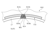
- the stationary seal ring 810 in the mechanical seal of the eighteenth embodiment is configured such that the inner diameter ends of the side surfaces 814b and 814c of the fluid lead-in/out groove 814 and the side surfaces 819b and 819c that define the inclined groove 861 are separated from each other in the circumferential direction. Inclined.
- the opening on the inner diameter side of the inclined groove 861 is enlarged in the circumferential direction, it is easy to introduce the sealed fluid F in the inner space S1 into the inclined groove 861. Further, since the side surfaces 814b, 814c and the side surfaces 819b, 819c are flat and continuous, the sealed fluid F can be easily introduced into the fluid inlet/outlet groove 814 through the inclined groove 861 .
- the stationary seal ring 910 in the mechanical seal of the nineteenth embodiment is configured such that the inner diameter ends of the side surfaces 914b and 914c of the fluid inlet/outlet groove 914 and the side surfaces 919b and 919c that define the inclined groove 961 are close to each other in the circumferential direction. Inclined.
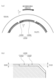
- the mechanical seal of the twentieth embodiment has a dynamic pressure generating mechanism 1030 having fluid inlet/outlet grooves 1040 and dynamic pressure generating grooves 1050 on the inner diameter side of the sliding surface of the stationary seal ring. formed.
- the mechanical seal of the twenty-first embodiment has a dynamic pressure generating mechanism 1130 having fluid inlet/outlet grooves 1140 and dynamic pressure generating grooves 1150 on the outer diameter side of the sliding surface of the stationary seal ring. is formed.
- a plurality of grooves 1230 and an enlarged surface 1217 are provided on an edge 1210e on the inner space S1 side of the sliding surface 1211 of the stationary seal ring 1210 of the twenty-second embodiment.
- the air A is present in the inner space S1 and the sealed fluid F is present in the outer space S2.
- the groove 1230 has a strip shape curved in an arc along the circumferential direction when viewed in the axial direction. More specifically, the groove 1230 has a bottom surface 1231 substantially parallel to the land 1212 , a downstream end surface 1232 as a positive pressure generating portion that rises substantially orthogonally to the land 1212 from the downstream end of the bottom surface 1231 , and an upstream end of the bottom surface 1231 .
- the stationary seal ring 1210 is composed of an inclined surface 1216 whose depth increases toward the inner peripheral surface of the stationary seal ring 1210 and side surfaces 1219b and 1219c rising from both circumferential ends of the inclined surface 1216. As shown in FIG.
- the bottom surface 1231, the downstream end surface 1232, and the upstream end surface 1233 are formed with a substantially rectangular opening 1215 extending in the circumferential direction and opening to the inner diameter side, and the opening 1215 communicates with the inner space S1. ing.
- the downstream end face 1232 and the upstream end face 1233 have the same radial length L10.
- the circumferential length L20 of the opening 1215 is longer than the radial length L10 of the downstream end surface 1232 and the upstream end surface 1233 (L10 ⁇ L20), and the circumferential length L20 is equal to the radial length L10. is about five times as large as
- the opening 1215 was open over the entire length of the inner diameter side extending in the circumferential direction, a wall extending substantially concentrically along the circumferential direction of the groove 1230 when viewed from the axial direction (peripheral wall surface in this embodiment). 1234), at least 1/3 or more, preferably 1/2 or more of the circumferential length thereof should be open.
- the circumferential length of the opening and the radial length of the groove may be appropriately changed as long as the circumferential length of the opening is larger than the radial length of the groove.
- the radial length L10 of the groove 1230 may be constant in the circumferential direction.
- the depth dimension of the groove 1230 may be changed as appropriate.
- the bottom surface of the groove 1230 has a flat surface and is formed parallel to the land 1212 , but the flat surface may be provided with a minute concave portion or formed so as to be inclined with respect to the land 1212 .
- the groove 1230 is formed symmetrically with respect to the line ⁇ 1 extending in the radial direction.
- the sealed fluid F on the outer diameter side slightly enters between the sliding surfaces 1211 and 21 due to capillary action and remains in the groove 1230.
- the sealed fluid F and the atmosphere A entering from the inner diameter side are mixed. Since the fluid to be sealed F has a higher viscosity than the air A, the amount of leakage from the groove 1230 to the low pressure side at the time of stopping is small.
- the atmosphere A continues to flow into the downstream end face 1232, thereby increasing the pressure in the vicinity of the downstream end face 1232 and generating a positive pressure. , flows out from the vicinity of the downstream end surface 1232 to its surroundings.
- the atmosphere A moving along the peripheral wall surface 1234 flows out from the downstream end surface 1232 between the sliding surfaces 1211 and 21, particularly toward the corners where the downstream end surface 1232 and the peripheral wall surface 1234 are substantially perpendicular to each other. , and flow out between the sliding surfaces 1211 and 21 from this corner.
- the pressure of the atmosphere A flowing out from the corner between the downstream end face 1232 and the peripheral wall surface 1234 is the highest, and the pressure gradually decreases toward the inner diameter side of the downstream end face 1232 or the upstream side of the peripheral wall surface 1234 from this corner. Become. In addition, since a centrifugal force acts on the air A, the air easily flows along the peripheral wall surface 1234 .
- the atmosphere A follows and moves toward the downstream end face 1232 to generate positive pressure, thereby generating negative pressure near the upstream end face 1233, and the atmosphere A is indicated by an arrow L5. 1215, and from the vicinity of the upstream end surface 1233 of the opening 1215 as indicated by an arrow L6.
- the atmosphere A flowing out from the vicinity of the downstream end face 1232 of the adjacent upstream groove 1230 is introduced from the upstream end face 1233 side as indicated by the arrow L7 due to the generated negative pressure.
- the sealed fluid F in the vicinity of the upstream end face 1233 of the groove 1230 between the sliding surfaces 1211 and 21 is recovered by the negative pressure generated at the upstream end face 1233 .
- the sealed fluid F since the sealed fluid F has a higher viscosity and a higher specific gravity than the atmosphere A, it is easily affected by rotation. It will move along the wall surface 1234 .
- the sealed fluid F that is about to flow out to the inner space S1 between the sliding surfaces 1211 and 21 can be recovered and reliably returned between the sliding surfaces 1211 and 21 together with the air A from the vicinity of the downstream end surface 1232. .
- the groove 1230 is formed with the opening 1215 that opens wide toward the inner space S1 along the circumferential direction, so that when the rotational speed of the rotary seal ring 20 is increased, the downstream end face of the groove 1230 Even if the pressure in the vicinity of 1232 increases, a large amount of air A can be taken in from the opening 1215 . Also, the air A can be positively introduced into the groove 1230 by the negative pressure generated in the vicinity of the upstream end surface 1233 of the groove 1230 .
- the opening 1215 is formed along the inner diameter side of the groove 1230, the atmosphere A can be sufficiently taken in from the opening 1215, and the air flow is high between the sliding surfaces 11 and 21 from the vicinity of the downstream end surface 1232. A positive pressure can be reliably generated.
- the atmosphere A can be positively taken in from a position deeper than the bottom surface 1231.
- the groove 1230 is formed axisymmetrically with respect to the line ⁇ 1, as indicated by the dotted line arrow in FIG.
- the atmosphere A moves from the downstream end surface 1232 toward the upstream end surface 1233, generating positive pressure near the upstream end surface 1233 and generating negative pressure near the downstream end surface 1232. It will happen. That is, it functions in the opposite way to the case where the rotary seal ring 20 rotates counterclockwise relative to the stationary seal ring 1210 . Therefore, it can be used regardless of the direction of relative rotation between the stationary seal ring 1210 and the rotary seal ring 20 .
- grooves 1230 are provided along the circumferential direction, it is easy to balance the pressure between the sliding surfaces 1211 and 21 in the circumferential direction.
- the grooves 1230 are evenly distributed in the circumferential direction, but they may be arranged irregularly. Also, the number of grooves 1230 can be freely changed.
- Example 22 a plurality of grooves are provided in the circumferential direction. may be
- downstream end surface of the groove is perpendicular to the circumferential direction and extends in the radial direction. You may incline in the direction. According to this, since the fluid is converged at the corner, it is possible to improve the ability to generate positive pressure.
- the upstream end face may be inclined in the circumferential direction so that the corner formed by the peripheral wall surface and the upstream end face forms an acute angle. According to this, high positive pressure generation capability can be exhibited regardless of the relative rotation direction between the stationary seal ring and the rotary seal ring.
- a plurality of grooves 1330 and an enlarged surface 1317 are provided on the edge 1310e of the sliding surface 1311 of the stationary seal ring 1310 on the inner space S1 side.
- the groove 1330 is deepest at the central portion in the circumferential direction, and becomes shallower in a stepwise manner from the central portion toward the downstream side in the rotational direction and the upstream side in the rotational direction. Further, this groove 1330 is formed symmetrically with respect to a line ⁇ 2 extending in the radial direction. In addition, in the groove 1330 of the twenty-third embodiment, the inclined surface 1316 does not continue to the inner peripheral surface of the stationary seal ring 1310 .
- the groove 1330 becomes shallower from the circumferential center toward the downstream end face 1332 and the upstream end face 1333, it is possible to efficiently generate positive pressure and negative pressure in the vicinity of the downstream end face 1332 and the upstream end face 1333. can.
- the groove is exemplified as a form in which the groove becomes shallow in a stepwise manner from the circumferential center to both ends in the circumferential direction, but this is not restrictive. It may extend linearly or in an arc so as to gradually become shallower toward both ends.
- a plurality of grooves 1430 and an enlarged surface 1417 are provided on the edge 1410 e on the inner diameter side of the stationary seal ring 1410 .
- the groove 1430 is composed of a first groove portion 1430C, a second groove portion 1430D on the downstream side, and a second groove portion 1430D' on the upstream side, and is formed in a substantially inverted ⁇ shape when viewed from the axial direction.
- the depth of groove 1430 is formed uniformly in the circumferential direction.
- the first groove portion 1430C opens into the inner space S1 and extends in an arc shape in the circumferential direction.
- the inner diameter side of the bottom surface of the first groove portion 1430 ⁇ /b>C forms an inclined surface 1416 substantially parallel to the expanded surface 1417 , and the other portion forms a flat surface substantially parallel to the land 1412 .
- the second groove portion 1430D includes an inclined portion 15D extending in the radial direction from the downstream end of the first groove portion 1430C while being inclined toward the downstream side in the rotation direction,
- the second groove portion 1430D is formed in an inverted V shape when viewed from the axial direction.
- the second groove portion 1430D′ includes an inclined portion 15D′ extending in the radial direction from the upstream end portion of the first groove portion 1430C while being inclined upstream in the rotational direction, and an outer diameter side end portion of the inclined portion 15D′. and an extended portion 15E′ as a negative pressure generating portion extending in the circumferential direction upstream in the rotational direction from the outer side.
- the inclined portion 15D and the inclined portion 15D' extend from the inner diameter side toward the outer diameter side as viewed from the axial direction so as to be inclined in directions away from each other, and the extending portions 15E and 15E' extend from the outer diameter side. extends in the circumferential direction.
- the inclined portion 15D is inclined.
- the atmosphere A moves along the two side wall portions 152a forming the groove 15D, and can be introduced smoothly into the second groove portion 1430D.
- the extension 15E of the second groove 1430D has a flow path cross section smaller than that of the first groove 1430C, a high positive pressure can be generated at the end 151a of the extension 15E.
- a negative pressure is generated at the end portion 151a' of the extension portion 15E'.
- the inclined portion 15D' is inclined.
- the air A moves along the two side wall portions 152c forming the inclined portion 15D', and can be smoothly introduced into the second groove portion 1430D'.
- the extension 15E' of the second groove 1430D' has a smaller cross-section than the first groove 1430C, a high positive pressure can be generated at the end 151a' of the extension 15E'.
- a negative pressure is generated at the end portion 151a of the extension portion 15E.
- a specific dynamic pressure generating mechanism 30 is formed on the outer diameter side of the stationary seal ring 1410 .
- the specific dynamic pressure generating mechanism 30 is composed of a plurality of fluid guide grooves 31 , an annular communication groove 32 , a Rayleigh step 33 and a reverse Rayleigh step 34 .
- each fluid guiding groove portion 31 At the outer diameter side end of the bottom surface of each fluid guiding groove portion 31, an inclined surface 31a is formed, the depth of which increases toward the outer diameter side. These fluid guiding grooves 31 communicate with the outer space S2 side and are evenly distributed in the circumferential direction. An enlarged surface 1418 parallel to the inclined surface 31a is formed on the edge portion 1410e' on the outer diameter side of the stationary seal ring 1410. As shown in FIG.
- the communication groove portion 32 extends annularly so as to communicate with the inner diameter side end portions of the respective fluid guiding groove portions 31 .
- the Rayleigh step 33 extends in the circumferential direction concentrically with the stationary seal ring 1410 toward the downstream side from a position on the outer diameter side of the communication groove portion 32 in the fluid guide groove portion 31 .
- the reverse Rayleigh step 34 extends circumferentially concentrically with the stationary seal ring 1410 toward the upstream side from a position on the outer diameter side of the communication groove portion 32 in the fluid guiding groove portion 31 .
- the fluid guide groove portion 31 and the communication groove portion 32 are formed deeper than the depth dimension of the groove 1430, and the Rayleigh step 33 and the reverse Rayleigh step 34 are formed at the same depth as the groove 1430.
- the sealed fluid F enters the specific dynamic pressure generating mechanism 30 when the rotary seal ring 20 is not rotating. 32, when the rotary seal ring 20 rotates counterclockwise relative to the stationary seal ring 1410, the sealed fluid F flows from the fluid guiding groove portion 31 to the Rayleigh step 33. side, dynamic pressure is generated in the Rayleigh step 33 . Particularly during low-speed rotation, the sealed fluid F flowing out between the sliding surfaces from the end portion 33A of the Rayleigh step 33 forms a liquid film to improve lubricity.
- the fluid guide groove portion 31 and the communication groove portion 32 are deep grooves, a large amount of the sealed fluid F can be retained, and poor lubrication between the sliding surfaces can be avoided during low speed rotation. Further, since the inclined surface 31a is formed at the outer diameter side end portion of the fluid guide groove portion 31, the sealed fluid F is smoothly introduced from the outer space S2.
- the sealed fluid F flows from the fluid guiding groove portion 31 to the reverse Rayleigh step 34. side, dynamic pressure is generated in the reverse Rayleigh step 34 .
- the sealed fluid F flowing out between the sliding surfaces from the end portion 34A of the reverse Rayleigh step 34 forms a liquid film to improve lubricity.
- the stationary seal ring 1410 of this embodiment can generate dynamic pressure by the Rayleigh step 33 and the reverse Rayleigh step 34 regardless of the relative rotational direction between the stationary seal ring 1410 and the rotary seal ring 20 .
- the second groove portion 1430D extends obliquely from the circumferential end portion of the first groove portion 1430C toward the outer diameter side.
- the first groove portion and the second groove portion may extend from the circumferential end portion of the first groove portion toward the outer diameter side, and may be formed in a substantially L shape in which the first groove portion and the second groove portion are substantially perpendicular when viewed from the axial direction.
- the second groove portion 1430D is configured by the inclined portion 15D and the extension portion 15E, but the configuration of the extension portion may be omitted.
- the Rayleigh step and the reverse Rayleigh step have the same depth dimension in this embodiment, they may have different depth dimensions. In addition, both may have the same or different circumferential length and radial width.
- the inside type is used to seal the sealed fluid F that tends to leak from the outer diameter side of the sliding surface toward the inner diameter side. It may be of an outside type that seals the sealed fluid F that tends to leak toward the outer diameter side.
- the groove 1530 provided in the stationary seal ring 1510 is composed of a first groove portion 1530C and a downstream second groove portion 1530D. ' is not provided. In this way, as indicated by the solid line arrow in FIG. 33, it may correspond only to the case where the rotary seal ring 20 rotates in the counterclockwise direction relative to the stationary seal ring 1510. .
- the groove 1630 provided in the stationary seal ring 1610 is composed of a first groove portion 1630C, a downstream second groove portion 1630D, and an upstream second groove portion 1630D'.
- the inclined portion 1615 of the second groove portion 1630D extends radially from the downstream end portion of the first groove portion 1630C while being inclined toward the upstream side in the rotation direction.
- the inclined portion 1615' of the second groove portion 1630D' extends radially from the upstream end of the first groove portion 1630C while being inclined downstream in the rotational direction.
- the inclined portion 1615 and the inclined portion 1615' extend from the inner diameter side toward the outer diameter side as seen from the axial direction so as to approach each other. 15E' extend circumferentially away from each other.
- a mechanical seal was used as a sliding component, but the sliding component may be a shaft sealing component other than a mechanical seal. Furthermore, the sliding component may be other than the shaft sealing component, such as a bearing component.
- the grooves are provided in the stationary seal ring, but the grooves may be provided in the rotary seal ring.
- one sliding ring of the present invention may be either a stationary seal ring or a rotating seal ring. Alternatively, it may be provided on both the stationary seal ring and the rotating seal ring.
- the sealed fluid side has been described as a high pressure side
- the leak side has been described as a low pressure side
- the sealed fluid side and the leak side may have substantially the same pressure.
- the spiral groove on the leak side is formed deeper than the dynamic pressure generating groove on the sealed fluid side, and positive pressure is generated in the dynamic pressure generating groove during low-speed rotation. , it is preferable to generate a positive pressure in the spiral grooves during high-speed rotation.
- the sealed fluid F is described as a high-pressure liquid, but the sealed fluid F is not limited to this, and may be a gas or a low-pressure liquid. good too.
- the fluid on the leak side is explained to be the atmosphere A, which is a low-pressure gas. It may be in the form of a mist.
- the bottom surface of the fluid inlet/outlet groove extends parallel to the flat surface of the land. You may incline so that it may become shallow towards. That is, the inclined surface should be deep toward the sealed fluid at a different angle from the bottom surface of the fluid inlet/outlet groove.
- the depth of the fluid inlet/outlet grooves may be deeper than the depth of the dynamic pressure generating grooves, and may be applied to Examples 20 and 21. Also, as in the 20th and 21st embodiments, the depth of the fluid inlet/outlet grooves may be the same as the depth of the dynamic pressure generating grooves, which may be applied to the 1st to 19th embodiments.
Landscapes
- Engineering & Computer Science (AREA)
- General Engineering & Computer Science (AREA)
- Mechanical Engineering (AREA)
- Chemical & Material Sciences (AREA)
- Oil, Petroleum & Natural Gas (AREA)
- Physics & Mathematics (AREA)
- Fluid Mechanics (AREA)
- Mechanical Sealing (AREA)
Priority Applications (6)
| Application Number | Priority Date | Filing Date | Title |
|---|---|---|---|
| EP26159624.1A EP4722568A2 (en) | 2021-08-25 | 2022-08-22 | Sliding component |
| JP2023543886A JPWO2023027002A1 (https=) | 2021-08-25 | 2022-08-22 | |
| CN202280057703.0A CN117859019A (zh) | 2021-08-25 | 2022-08-22 | 滑动部件 |
| EP26159637.3A EP4722569A2 (en) | 2021-08-25 | 2022-08-22 | Sliding component |
| EP22861290.9A EP4394215A4 (en) | 2021-08-25 | 2022-08-22 | SLIDING COMPONENT |
| KR1020247006435A KR20240038065A (ko) | 2021-08-25 | 2022-08-22 | 슬라이딩 부품 |
Applications Claiming Priority (4)
| Application Number | Priority Date | Filing Date | Title |
|---|---|---|---|
| JP2021137305 | 2021-08-25 | ||
| JP2021-137305 | 2021-08-25 | ||
| JP2022-080279 | 2022-05-16 | ||
| JP2022080279 | 2022-05-16 |
Publications (1)
| Publication Number | Publication Date |
|---|---|
| WO2023027002A1 true WO2023027002A1 (ja) | 2023-03-02 |
Family
ID=85322284
Family Applications (1)
| Application Number | Title | Priority Date | Filing Date |
|---|---|---|---|
| PCT/JP2022/031493 Ceased WO2023027002A1 (ja) | 2021-08-25 | 2022-08-22 | 摺動部品 |
Country Status (4)
| Country | Link |
|---|---|
| EP (3) | EP4722568A2 (https=) |
| JP (1) | JPWO2023027002A1 (https=) |
| KR (1) | KR20240038065A (https=) |
| WO (1) | WO2023027002A1 (https=) |
Cited By (1)
| Publication number | Priority date | Publication date | Assignee | Title |
|---|---|---|---|---|
| WO2026083929A1 (ja) * | 2024-10-18 | 2026-04-23 | イーグル工業株式会社 | 摺動部品 |
Citations (7)
| Publication number | Priority date | Publication date | Assignee | Title |
|---|---|---|---|---|
| JPS4933614B1 (https=) * | 1968-06-05 | 1974-09-07 | ||
| JPH07260009A (ja) * | 1994-03-22 | 1995-10-13 | Nippon Pillar Packing Co Ltd | 非接触形軸封装置 |
| WO2016035860A1 (ja) * | 2014-09-04 | 2016-03-10 | イーグル工業株式会社 | メカニカルシール |
| JP6444492B2 (ja) | 2015-04-15 | 2018-12-26 | イーグル工業株式会社 | 摺動部品 |
| WO2020162348A1 (ja) * | 2019-02-04 | 2020-08-13 | イーグル工業株式会社 | 摺動部品 |
| WO2020166588A1 (ja) * | 2019-02-15 | 2020-08-20 | イーグル工業株式会社 | 摺動部品 |
| JP2020173020A (ja) * | 2019-04-09 | 2020-10-22 | イーグル工業株式会社 | 摺動部品 |
Family Cites Families (5)
| Publication number | Priority date | Publication date | Assignee | Title |
|---|---|---|---|---|
| JPH0620155Y2 (ja) | 1987-09-11 | 1994-05-25 | シチズン時計株式会社 | 時計の時刻修正機構 |
| US5224714A (en) * | 1990-07-18 | 1993-07-06 | Ebara Corporation | Noncontacting face seal |
| CN1167890C (zh) * | 2001-01-18 | 2004-09-22 | 王玉明 | 可双向旋转的螺旋槽端面密封装置 |
| US7377518B2 (en) * | 2004-05-28 | 2008-05-27 | John Crane Inc. | Mechanical seal ring assembly with hydrodynamic pumping mechanism |
| KR102616659B1 (ko) * | 2019-04-24 | 2023-12-21 | 이구루코교 가부시기가이샤 | 슬라이딩 부품 |
-
2022
- 2022-08-22 WO PCT/JP2022/031493 patent/WO2023027002A1/ja not_active Ceased
- 2022-08-22 JP JP2023543886A patent/JPWO2023027002A1/ja active Pending
- 2022-08-22 EP EP26159624.1A patent/EP4722568A2/en active Pending
- 2022-08-22 EP EP26159637.3A patent/EP4722569A2/en active Pending
- 2022-08-22 KR KR1020247006435A patent/KR20240038065A/ko active Pending
- 2022-08-22 EP EP22861290.9A patent/EP4394215A4/en active Pending
Patent Citations (7)
| Publication number | Priority date | Publication date | Assignee | Title |
|---|---|---|---|---|
| JPS4933614B1 (https=) * | 1968-06-05 | 1974-09-07 | ||
| JPH07260009A (ja) * | 1994-03-22 | 1995-10-13 | Nippon Pillar Packing Co Ltd | 非接触形軸封装置 |
| WO2016035860A1 (ja) * | 2014-09-04 | 2016-03-10 | イーグル工業株式会社 | メカニカルシール |
| JP6444492B2 (ja) | 2015-04-15 | 2018-12-26 | イーグル工業株式会社 | 摺動部品 |
| WO2020162348A1 (ja) * | 2019-02-04 | 2020-08-13 | イーグル工業株式会社 | 摺動部品 |
| WO2020166588A1 (ja) * | 2019-02-15 | 2020-08-20 | イーグル工業株式会社 | 摺動部品 |
| JP2020173020A (ja) * | 2019-04-09 | 2020-10-22 | イーグル工業株式会社 | 摺動部品 |
Non-Patent Citations (1)
| Title |
|---|
| See also references of EP4394215A4 |
Cited By (1)
| Publication number | Priority date | Publication date | Assignee | Title |
|---|---|---|---|---|
| WO2026083929A1 (ja) * | 2024-10-18 | 2026-04-23 | イーグル工業株式会社 | 摺動部品 |
Also Published As
| Publication number | Publication date |
|---|---|
| KR20240038065A (ko) | 2024-03-22 |
| EP4722569A2 (en) | 2026-04-08 |
| JPWO2023027002A1 (https=) | 2023-03-02 |
| EP4722568A2 (en) | 2026-04-08 |
| EP4394215A1 (en) | 2024-07-03 |
| EP4394215A4 (en) | 2025-08-06 |
Similar Documents
| Publication | Publication Date | Title |
|---|---|---|
| JP7366945B2 (ja) | 摺動部品 | |
| WO2019139107A1 (ja) | 摺動部品 | |
| JP6910371B2 (ja) | しゅう動部品 | |
| WO2020162025A1 (ja) | 摺動部品 | |
| KR102724015B1 (ko) | 슬라이딩 부품 | |
| JP6456950B2 (ja) | 摺動部品 | |
| JP7404351B2 (ja) | 摺動部品 | |
| KR20210111856A (ko) | 슬라이딩 부품 | |
| EP4317728B1 (en) | Sliding components | |
| WO2023027002A1 (ja) | 摺動部品 | |
| WO2023286590A1 (ja) | 摺動部品 | |
| WO2023053964A1 (ja) | 摺動部品 | |
| EP4644733A1 (en) | Sliding components | |
| WO2023027003A1 (ja) | 摺動部品 | |
| JP7520470B2 (ja) | 摺動部品 | |
| EP4130523B1 (en) | Sliding component | |
| WO2023223914A1 (ja) | 摺動部品 | |
| CN117859019A (zh) | 滑动部件 | |
| WO2026083929A1 (ja) | 摺動部品 | |
| JP2026073699A (ja) | 摺動部品 | |
| WO2024053637A1 (ja) | 摺動部品 | |
| WO2026079108A1 (ja) | 摺動部品 | |
| WO2022190944A1 (ja) | 摺動部品 | |
| KR20260049805A (ko) | 슬라이딩 부품 | |
| WO2025239228A1 (ja) | 摺動部品 |
Legal Events
| Date | Code | Title | Description |
|---|---|---|---|
| 121 | Ep: the epo has been informed by wipo that ep was designated in this application |
Ref document number: 22861290 Country of ref document: EP Kind code of ref document: A1 |
|
| WWE | Wipo information: entry into national phase |
Ref document number: 2023543886 Country of ref document: JP |
|
| WWE | Wipo information: entry into national phase |
Ref document number: 202280057703.0 Country of ref document: CN Ref document number: 18686250 Country of ref document: US |
|
| ENP | Entry into the national phase |
Ref document number: 20247006435 Country of ref document: KR Kind code of ref document: A |
|
| WWE | Wipo information: entry into national phase |
Ref document number: 1020247006435 Country of ref document: KR |
|
| WWE | Wipo information: entry into national phase |
Ref document number: 2022861290 Country of ref document: EP |
|
| NENP | Non-entry into the national phase |
Ref country code: DE |
|
| ENP | Entry into the national phase |
Ref document number: 2022861290 Country of ref document: EP Effective date: 20240325 |