WO2023026966A1 - 光学素子駆動装置、カメラモジュール及びカメラ搭載装置 - Google Patents
光学素子駆動装置、カメラモジュール及びカメラ搭載装置 Download PDFInfo
- Publication number
- WO2023026966A1 WO2023026966A1 PCT/JP2022/031307 JP2022031307W WO2023026966A1 WO 2023026966 A1 WO2023026966 A1 WO 2023026966A1 JP 2022031307 W JP2022031307 W JP 2022031307W WO 2023026966 A1 WO2023026966 A1 WO 2023026966A1
- Authority
- WO
- WIPO (PCT)
- Prior art keywords
- ois
- section
- movable
- optical element
- stage
- Prior art date
Links
- 230000003287 optical effect Effects 0.000 title claims abstract description 150
- 238000003384 imaging method Methods 0.000 claims description 18
- 238000003825 pressing Methods 0.000 claims description 14
- 238000001514 detection method Methods 0.000 claims description 11
- 238000012545 processing Methods 0.000 claims description 6
- 238000000034 method Methods 0.000 claims description 5
- 230000002093 peripheral effect Effects 0.000 description 32
- 239000000758 substrate Substances 0.000 description 26
- 230000005540 biological transmission Effects 0.000 description 22
- 238000012937 correction Methods 0.000 description 11
- 230000033001 locomotion Effects 0.000 description 10
- 229920001230 polyarylate Polymers 0.000 description 9
- 230000006399 behavior Effects 0.000 description 7
- 238000003780 insertion Methods 0.000 description 6
- 230000037431 insertion Effects 0.000 description 6
- 229920000106 Liquid crystal polymer Polymers 0.000 description 4
- 239000004977 Liquid-crystal polymers (LCPs) Substances 0.000 description 4
- 239000000853 adhesive Substances 0.000 description 4
- 230000001070 adhesive effect Effects 0.000 description 4
- 210000000078 claw Anatomy 0.000 description 4
- 239000004020 conductor Substances 0.000 description 3
- 238000010586 diagram Methods 0.000 description 3
- 239000000956 alloy Substances 0.000 description 2
- 229910045601 alloy Inorganic materials 0.000 description 2
- 230000009977 dual effect Effects 0.000 description 2
- 239000000463 material Substances 0.000 description 2
- 238000002156 mixing Methods 0.000 description 2
- 238000012986 modification Methods 0.000 description 2
- 230000004048 modification Effects 0.000 description 2
- 238000000465 moulding Methods 0.000 description 2
- 239000011347 resin Substances 0.000 description 2
- 229920005989 resin Polymers 0.000 description 2
- 238000007792 addition Methods 0.000 description 1
- 239000003990 capacitor Substances 0.000 description 1
- 229910010293 ceramic material Inorganic materials 0.000 description 1
- 230000000295 complement effect Effects 0.000 description 1
- 239000000470 constituent Substances 0.000 description 1
- 230000000694 effects Effects 0.000 description 1
- 230000005489 elastic deformation Effects 0.000 description 1
- 238000005530 etching Methods 0.000 description 1
- 238000009434 installation Methods 0.000 description 1
- 239000000696 magnetic material Substances 0.000 description 1
- 239000002184 metal Substances 0.000 description 1
- 229910052751 metal Inorganic materials 0.000 description 1
- 229910044991 metal oxide Inorganic materials 0.000 description 1
- 150000004706 metal oxides Chemical class 0.000 description 1
- 239000012778 molding material Substances 0.000 description 1
- 230000000149 penetrating effect Effects 0.000 description 1
- 230000004043 responsiveness Effects 0.000 description 1
- 238000005096 rolling process Methods 0.000 description 1
- 239000004065 semiconductor Substances 0.000 description 1
- 230000006641 stabilisation Effects 0.000 description 1
- 238000011105 stabilization Methods 0.000 description 1
Images


Classifications
-
- G—PHYSICS
- G02—OPTICS
- G02B—OPTICAL ELEMENTS, SYSTEMS OR APPARATUS
- G02B7/00—Mountings, adjusting means, or light-tight connections, for optical elements
- G02B7/02—Mountings, adjusting means, or light-tight connections, for optical elements for lenses
-
- G—PHYSICS
- G02—OPTICS
- G02B—OPTICAL ELEMENTS, SYSTEMS OR APPARATUS
- G02B7/00—Mountings, adjusting means, or light-tight connections, for optical elements
- G02B7/02—Mountings, adjusting means, or light-tight connections, for optical elements for lenses
- G02B7/04—Mountings, adjusting means, or light-tight connections, for optical elements for lenses with mechanism for focusing or varying magnification
- G02B7/08—Mountings, adjusting means, or light-tight connections, for optical elements for lenses with mechanism for focusing or varying magnification adapted to co-operate with a remote control mechanism
-
- G—PHYSICS
- G03—PHOTOGRAPHY; CINEMATOGRAPHY; ANALOGOUS TECHNIQUES USING WAVES OTHER THAN OPTICAL WAVES; ELECTROGRAPHY; HOLOGRAPHY
- G03B—APPARATUS OR ARRANGEMENTS FOR TAKING PHOTOGRAPHS OR FOR PROJECTING OR VIEWING THEM; APPARATUS OR ARRANGEMENTS EMPLOYING ANALOGOUS TECHNIQUES USING WAVES OTHER THAN OPTICAL WAVES; ACCESSORIES THEREFOR
- G03B15/00—Special procedures for taking photographs; Apparatus therefor
-
- G—PHYSICS
- G03—PHOTOGRAPHY; CINEMATOGRAPHY; ANALOGOUS TECHNIQUES USING WAVES OTHER THAN OPTICAL WAVES; ELECTROGRAPHY; HOLOGRAPHY
- G03B—APPARATUS OR ARRANGEMENTS FOR TAKING PHOTOGRAPHS OR FOR PROJECTING OR VIEWING THEM; APPARATUS OR ARRANGEMENTS EMPLOYING ANALOGOUS TECHNIQUES USING WAVES OTHER THAN OPTICAL WAVES; ACCESSORIES THEREFOR
- G03B17/00—Details of cameras or camera bodies; Accessories therefor
- G03B17/02—Bodies
-
- G—PHYSICS
- G03—PHOTOGRAPHY; CINEMATOGRAPHY; ANALOGOUS TECHNIQUES USING WAVES OTHER THAN OPTICAL WAVES; ELECTROGRAPHY; HOLOGRAPHY
- G03B—APPARATUS OR ARRANGEMENTS FOR TAKING PHOTOGRAPHS OR FOR PROJECTING OR VIEWING THEM; APPARATUS OR ARRANGEMENTS EMPLOYING ANALOGOUS TECHNIQUES USING WAVES OTHER THAN OPTICAL WAVES; ACCESSORIES THEREFOR
- G03B30/00—Camera modules comprising integrated lens units and imaging units, specially adapted for being embedded in other devices, e.g. mobile phones or vehicles
-
- G—PHYSICS
- G03—PHOTOGRAPHY; CINEMATOGRAPHY; ANALOGOUS TECHNIQUES USING WAVES OTHER THAN OPTICAL WAVES; ELECTROGRAPHY; HOLOGRAPHY
- G03B—APPARATUS OR ARRANGEMENTS FOR TAKING PHOTOGRAPHS OR FOR PROJECTING OR VIEWING THEM; APPARATUS OR ARRANGEMENTS EMPLOYING ANALOGOUS TECHNIQUES USING WAVES OTHER THAN OPTICAL WAVES; ACCESSORIES THEREFOR
- G03B5/00—Adjustment of optical system relative to image or object surface other than for focusing
-
- H—ELECTRICITY
- H04—ELECTRIC COMMUNICATION TECHNIQUE
- H04N—PICTORIAL COMMUNICATION, e.g. TELEVISION
- H04N23/00—Cameras or camera modules comprising electronic image sensors; Control thereof
- H04N23/50—Constructional details
-
- H—ELECTRICITY
- H04—ELECTRIC COMMUNICATION TECHNIQUE
- H04N—PICTORIAL COMMUNICATION, e.g. TELEVISION
- H04N23/00—Cameras or camera modules comprising electronic image sensors; Control thereof
- H04N23/57—Mechanical or electrical details of cameras or camera modules specially adapted for being embedded in other devices
Definitions
- the present invention relates to an optical element driving device for driving an optical element, a camera module, and a camera mounting device.
- a camera module is installed in a thin camera-equipped device such as a smartphone.
- An optical element driving device for driving an optical element is used in such a camera module.
- the optical element driving device has an autofocus function (hereinafter referred to as "AF function", AF: Auto Focus).
- AF function autofocus function
- the optical element driving device drives a lens (optical element) with an AF function to automatically perform focusing when photographing a subject.
- Patent Document 1 discloses a lens holder that holds a lens, a ball member that supports the lens holder movably in the optical axis direction, and an actuator that drives the lens holder movably in the optical axis direction.
- a lens driver is shown.
- one actuator is arranged at one corner of a rectangular base in plan view.
- Patent Document 1 As described above, the lens and the lens holder are driven by a single actuator. Therefore, when the weight of the lens increases, the thrust force for driving the lens becomes insufficient, which causes problems such as a long time required for focusing. may occur. By providing a plurality of actuators, it is possible to increase the thrust for driving the lens, but in that case, it becomes difficult to reduce the size of the camera module. Therefore, there is a demand for an optical element driving device that can increase the thrust force for driving the lens and can achieve miniaturization.
- An object of the present invention is to provide an optical element driving device, a camera module, and a camera mounting device that can increase the thrust for driving the optical element and can be made smaller.
- An optical element driving device includes: a first movable portion configured to be movable in the optical axis direction by the first driving portion while holding the optical element; a second movable section configured by stacking a first stage and a second stage on a base so as to be movable together with the first movable section in a direction perpendicular to the optical axis by a second driving section; with The second drive section is arranged along each of two orthogonal side surfaces of the second movable section, The first drive portions are arranged at diagonal positions of the second movable portion.
- a camera module includes: the optical element driving device; an imaging unit that captures a subject image formed by the optical element; Prepare.
- a camera-equipped device includes: A camera-equipped device that is information equipment or transportation equipment, the camera module; an image processing unit that processes image information obtained by the camera module; Prepare.
- the optical element driving device in the optical element driving device, it is possible to increase the thrust for driving the optical element and to reduce the size.
- FIG. 1 is a front view showing a smart phone equipped with a camera module according to an embodiment of the invention
- FIG. 1B is a rear view of the smartphone shown in FIG. 1A
- FIG. It is a perspective view which shows a camera module and an imaging part.
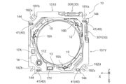
- FIG. 3 is a perspective view of an optical element driving device body included in the optical element driving device of the camera module
- 4 is a perspective view from a different direction of the main body of the optical element driving device shown in FIG. 3
- FIG. 5 is an exploded perspective view of the main body of the optical element driving device shown in FIGS. 3 and 4
- FIG. 6 is an exploded perspective view of the OIS movable portion shown in FIG. 5;
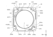
- FIG. 5 is a plan view of the main body of the optical element driving device shown in FIGS. 3 and 4;
- FIG. 4 is a plan view showing a positional relationship between an OIS fixed portion and an AF movable portion;
- FIG. 4 is a plan view of an OIS fixing portion; It is a bottom view of an OIS fixing
- FIG. 15B is a perspective view of the automobile shown in FIG. 15A as viewed obliquely from the rear;
- FIG. 1A and 1B are diagrams showing a smartphone M (an example of a camera-equipped device) equipped with a camera module A according to the present embodiment.
- 1A is a front view of the smartphone M
- FIG. 1B is a rear view of the smartphone M.
- FIG. 1A is a front view of the smartphone M
- FIG. 1B is a rear view of the smartphone M.
- Smartphone M has a dual camera consisting of two rear cameras OC1 and OC2.
- the camera module A is applied to the rear cameras OC1 and OC2.
- Camera module A has an AF function and a shake correction function (hereinafter referred to as "OIS function", OIS: Optical Image Stabilization).
- OIS function Optical Image Stabilization
- the camera module A uses the AF function to automatically adjust the focus when shooting a subject, and the OIS function to optically correct the shake (vibration) that occurs during shooting to shoot images without image blur. can do.
- FIG. 2 is a perspective view showing the camera module A and the imaging section 5.
- FIG. 3 and 4 are perspective views of the optical element driving device main body 4 included in the optical element driving device 1 of the camera module A shown in FIG.
- FIG. 4 is a diagram of the optical element driving device main body 4 shown in FIG. 3 rotated by 180° around the Z-axis.
- this embodiment will be described using an orthogonal coordinate system (X, Y, Z).
- the drawings to be described later are also shown in a common orthogonal coordinate system (X, Y, Z).
- the camera module A when photographing is performed by the smartphone M, the camera module A is mounted so that the X direction is the up-down direction (or the left-right direction), the Y direction is the left-right direction (or the up-down direction), and the Z direction is the front-back direction. . That is, the Z direction is the optical axis direction, and in FIGS. 2 to 4, the upper side (+Z side) is the light receiving side in the optical axis direction, and the lower side ( ⁇ Z side) is the imaging side in the optical axis direction.
- optical axis orthogonal direction the X direction and the Y direction orthogonal to the Z axis
- XY plane the XY plane
- optical axis orthogonal plane the direction orthogonal to the optical axis
- the camera module A includes an optical element driving device 1 that realizes an AF function and an OIS function, a lens unit 2 configured by housing a lens in a cylindrical lens barrel, and an image formed by the lens unit 2.
- An imaging unit 5 and the like are provided for capturing an image of the subject. That is, the optical element driving device 1 is a so-called lens driving device that drives the lens portion 2 as an optical element.
- the optical element driving device main body 4 is covered with a cover 3 on the outside.
- the cover 3 is a lidded quadrangular cylinder having a rectangular shape in a plan view seen from the optical axis direction. In this embodiment, the cover 3 has a square shape in plan view.
- the cover 3 has a substantially circular opening 301 on its upper surface.
- the lens unit 2 is accommodated in the opening 401 of the optical element driving device main body 4 and faces the outside through the opening 301 of the cover 3. For example, as it moves in the optical axis direction, the lens unit 2 moves toward the light receiving side of the opening surface of the cover 3 in the optical axis direction.
- the inner wall of the cover 3 is fixed to the base 21 (see FIG. 5 which will be described later) of the OIS fixing portion 20 of the optical element driving device main body 4 by, for example, adhesion, and the OIS movable portion 10 etc. (FIG. ).
- the cover 3 has a member that blocks electromagnetic waves from the outside of the optical element driving device 1, for example, a shield member made of a magnetic material.
- the imaging unit 5 is arranged on the imaging side of the optical element driving device 1 in the optical axis direction.
- the imaging unit 5 has, for example, an image sensor substrate 501 , an imaging device 502 mounted on the image sensor substrate 501 , and a control unit 503 .
- the imaging device 502 is configured by, for example, a CCD (charge-coupled device) image sensor, a CMOS (complementary metal oxide semiconductor) image sensor, or the like, and captures an object image formed by the lens unit 2 .
- CCD charge-coupled device
- CMOS complementary metal oxide semiconductor
- the control unit 503 is composed of, for example, a control IC, and controls driving of the optical element driving device 1 .
- the optical element driving device 1 is mounted on the image sensor substrate 501 and mechanically and electrically connected.
- the control unit 503 may be provided on the image sensor substrate 501, or may be provided on a camera-equipped device (in this embodiment, the smart phone M) on which the camera module A is mounted.
- FIG. 5 is an exploded perspective view of the main body 4 of the optical element driving device.
- FIG. 6 is an exploded perspective view of the OIS movable portion 10.
- FIG. FIG. 7 is a plan view of the main body 4 of the optical element driving device. The optical element driving device main body 4 will be described with reference to FIGS. 5 to 7 as well.
- the optical element driving device main body 4 includes an OIS movable portion 10, an OIS fixed portion 20, an OIS driving portion 30, an OIS supporting portion 40, and an OIS biasing member 50, as shown in FIG.
- the OIS movable portion 10 is a portion that can hold the lens portion 2 and that swings within a plane perpendicular to the optical axis during shake correction.
- the OIS movable section 10 has an AF section 11, a second stage 14, and an OIS support section 40 (Y-direction reference ball 42) (see FIG. 6).
- the AF section 11 has an AF movable section 12, a first stage 13, an AF drive section 15, and AF support sections 16A and 16B (see FIGS. 5 and 6).
- the OIS fixing part 20 has a base 21 and an OIS supporting part 40 (X-direction reference ball 41), as shown in FIG.
- the OIS fixing section 20 is arranged at a position separated from the OIS movable section 10 in the optical axis direction via the OIS support section 40, and the OIS support section 40 allows the OIS movable section 10 to swing in the direction perpendicular to the optical axis. This is the supporting part.
- the OIS movable section 10 is spaced apart from the base 21 in the optical axis direction via the X-direction reference ball 41 , and the base 21 is connected to the OIS movable section 10 via the X-direction reference ball 41 . is swingably supported.
- the OIS movable part 10 and the OIS fixed part 20 are elastically connected by the OIS biasing member 50 so as to be biased toward each other, in other words, to hold the OIS support part 40 sandwiched therebetween. (see FIGS. 3-5).
- the OIS biasing member 50 is made of a conductive material. Although the details will be described later, the OIS biasing member 50 also functions as a connection member that forms a conductive path between a circuit for driving the lens unit 2 and the like and a circuit on the OIS fixing unit 20 side.
- the OIS biasing members 50 are arranged at the four corner portions (corner portions) in plan view of the optical element driving device main body 4 (see FIGS. 3 and 4).
- the OIS driving section 30 has a first OIS driving section 30X that drives the OIS movable section 10 in the X direction, and a second OIS driving section 30Y that drives the OIS movable section 10 in the Y direction.
- the entire OIS movable section 10 including the AF section 11 moves as a movable body with respect to movement in the X direction.
- the base 21 of the OIS fixing portion 20 constitutes a fixed body
- the X direction reference ball 41 functions as an OIS support portion 40 that supports the OIS movable portion 10 so as to be swingable in the X direction. do.
- the AF section 11 moves as a movable body with respect to movement in the Y direction.
- the second stage 14 constitutes a fixed body together with the base 21, and the Y direction reference ball 42 functions as an OIS support portion 40 that supports the AF portion 11 so as to be swingable in the Y direction. do.
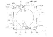
- [OIS fixing part] 9 is a plan view of the OIS fixing portion 20.
- FIG. 10 is a bottom view of the OIS fixing portion 20.
- FIG. The OIS fixing unit 20 will be described with reference to FIGS. 9 and 10 as well.
- the OIS fixing section 20 has a base 21, a substrate 22, a first OIS driving section 30X, and an OIS supporting section 40 (X-direction reference ball 41) (see FIG. 5).
- the base 21 is formed of, for example, polyarylate (PAR), a PAR alloy (for example, PAR/PC) obtained by mixing a plurality of resin materials including PAR, or a molding material made of liquid crystal polymer.
- the base 21 is a rectangular member in plan view and has a circular opening 211 in the center.
- the base 21 has an OIS motor fixing portion 217 on which the first OIS driving portion 30X is arranged.
- the OIS motor fixing portion 217 is provided, for example, near one corner of the base 21, protrudes from the base 21 toward the light receiving side in the optical axis direction, and has a shape capable of holding the first OIS driving portion 30X. (see Figure 5).
- the base 21 also has an X-direction reference ball holding portion 218 that holds the X-direction reference ball 41 that constitutes the OIS support portion 40 .
- the X-direction reference ball 41 is sandwiched between the X-direction reference ball holding portion 218 and the X-direction reference ball holding portion 144 (see FIG. 11 described later) of the second stage 14 facing each other in the Z direction.
- the X-direction reference ball holding portion 218 and the X-direction reference ball holding portion 144 are recesses having rectangular openings extending in the X direction.
- the X-direction reference ball holding portion 218 and the X-direction reference ball holding portion 144 have, for example, a substantially V-shaped (tapered) cross-sectional shape or a substantially U-shaped cross section so that the groove width becomes narrower toward the bottom surface of the recess. formed to be
- the groove formed by the recess having the cross-sectional shape described above is formed parallel to the X direction, so that the X direction reference ball holding portion 218 and the X direction reference ball holding portion 144 are sandwiched.
- the ball 41 can roll in the X direction within the recess. That is, the base 21 supports the OIS movable part 10 (second stage 14) through the X-direction reference ball 41 so as to be movable in the X-direction.
- the X-direction reference ball holding portion 218 and the X-direction reference ball holding portion 144 are arranged at four corners of the rectangular base 21 and the second stage 14, and the OIS movable portion 10 (second stage 14) has four It is supported on the base 21 by the X-direction reference ball 41, that is, at four points. In this way, the X-direction reference ball 41 is sandwiched by multi-point contact, so that it rolls stably in the Y-direction.
- the OIS movable section 10 (second stage 14) should be supported by the base 21 at least at three points or more.
- the X-direction reference ball holding portion 218 and the X-direction reference ball holding portion 218 and The X-direction reference ball holding portion 144 may be arranged.
- a plurality of terminals 23 and power supply lines 25Xa, 25Xb, 25Ya, 25Yb, 25Za, 25Zb, 25Zc, and 25Zd are arranged on the outer edge of the base 21 (see FIGS. 9 and 10).
- the terminals 23 are embedded in the base 21 by, for example, insert molding, with one end of each terminal exposed from the top surface of the base 21 (see FIG. 9) and the other end exposed from the bottom surface of the base 21. (see FIG. 10).
- the terminal 23 is a terminal for power supply and signal to driver ICs 221X, 221Y, and 221Z which drive the first OIS driving section 30X, the second OIS driving section 30Y, and the AF driving section 15, respectively.
- the power supply wirings 25Xa and 25Xb are formed so as to be exposed on the upper surface of the base 21 from the inner end to the outer end in the outer edge portion of the base 21 (see FIG. 9).
- the power supply wirings 25Ya and 25Yb have inner ends exposed on the top surface of the base 21 (see FIG. 9) and outer ends exposed on the bottom surface of the base 21 at the corners that are the outer edge portions of the base 21. (see FIG. 10).
- the power supply wirings 25Za, 25Zb, 25Zc, and 25Zd have inner ends exposed on the upper surface of the base 21 at corners, which are outer edge portions of the base 21 (see FIG. 9), and outer ends of the base 21. (see FIG. 10).
- the inner ends of the power supply wirings 25Xa and 25Xb are connected to the substrate 22 and connected to the driver IC 221X via a booster section 60, which will be described later. Outer ends of the power supply lines 25Xa and 25Xb are connected to the first OIS driver 30X. Further, the inner ends of the power supply wirings 25Ya and 25Yb are connected to the substrate 22 and connected to the driver IC 221Y via the boosting section 60, which will be described later. The outer ends of the power supply wirings 25Ya and 25Yb are connected to the second OIS driving section 30Y via the OIS biasing member 50 and the power supply wirings 18Ya and 18Yb.
- the inner ends of the power supply wirings 25Za, 25Zb, 25Zc, and 25Zd are connected to the substrate 22 and connected to the driver IC 221Z via a boosting section 60, which will be described later.
- the outer ends of the power supply wirings 25Za, 25Zb, 25Zc and 25Zd are connected to the two AF drive units 15 via the OIS biasing member 50 and the power supply wirings 18Za, 18Zb, 18Zc and 18Zd.
- the driver IC 221X is a 1-channel driver IC that controls driving of one drive unit
- the driver IC 221Y is also a similar 1-channel driver IC
- the driver IC 221Z is a two-channel driver IC that controls driving of the two drive units.
- the number of channels in the driver ICs 221X, 221Y, and 221Z can be appropriately changed according to the number of drive units to be driven.
- the substrate 22 is arranged on the light receiving side of the base 21 in the optical axis direction.
- the substrate 22 is electrically connected to terminals 23 exposed on the upper surface of the base 21, and the terminals 23 are connected to the driver ICs 221X, 221Y, 221Z, etc. via wiring (not shown) formed on the substrate 22.
- the driver ICs 221X, 221Y, and 221Z are connected to power supply wirings 25Xa, 25Xb, 25Ya, 25Yb, 25Za, 25Zb, 25Zc, and 25Zd via wiring (not shown) formed on the substrate 22 .
- the power supply lines 25Xa, 25Xb, 25Ya, 25Yb, 25Za, 25Zb, 25Zc, and 25Zd are connected to the first OIS driving section 30X, the second OIS driving section 30Y, and the AF driving section 15 as described above.
- the driver ICs 221X, 221Y, and 221Z are arranged on the light-receiving side of the substrate 22 in the optical axis direction, and each have a magnetic sensor (not shown).
- These magnetic sensors are composed of, for example, Hall elements, TMR (Tunnel Magneto Resistance) sensors, etc., and detect magnetic fields generated by magnets 17X, 17Y, and 17Z (magnets) described later, and detect X, Y, and A position in the Z direction is detected magnetically.
- the driver ICs 221X, 221Y, and 221Z are provided in a region where the AF drive section 15, AF support sections 16A, 16B, first OIS drive section 30X, and second OIS drive section 30Y are not arranged (see FIG. 5). reference). That is, it is provided in a region near one corner of the rectangular base 21 in plan view (see FIG. 9). As a result, the driver ICs 221X, 221Y, and 221Z can be concentrated in one area, and the space inside the optical element driving device main body 4 can be effectively utilized.
- a magnet 17X is arranged on the bottom side of the second stage 14 that moves in the X direction, and the driver IC 221X and the magnet 17X are arranged to face each other.
- the X-direction position of the second stage 14, that is, the X-direction position of the OIS movable section 10 is detected by an X-direction position detection section including the driver IC 221X and the magnet 17X.
- a magnet 17Y is arranged on the bottom side of the first stage 13 that moves in the Y direction, and the driver IC 221Y and the magnet 17Y are arranged so as to face each other.
- a Y-direction position detection unit including the driver IC 221Y and the magnet 17Y detects the Y-direction position of the first stage 13, that is, the Y-direction position of the OIS movable unit 10.
- a magnet 17Z is arranged on the bottom side of the AF movable portion 12 that moves in the Z direction, and the driver IC 221Z and the magnet 17Z are arranged so as to oppose each other.
- the Z-direction position of the AF movable section 12 is detected by the Z-direction position detection section including the driver IC 221Z and the magnet 17Z.
- an optical sensor such as a photoreflector may be used to detect the positions of the OIS movable section 10 in the X and Y directions and the position of the AF movable section 12 in the Z direction.
- the optical element driving device 1 ultrasonic motors including piezoelectric elements are used as the AF driving section 15, the first OIS driving section 30X, and the second OIS driving section 30Y from the viewpoint of miniaturization. Since a relatively large drive voltage is required to drive the ultrasonic motor, this embodiment includes a booster 60 that boosts the input voltage to a desired voltage.
- the boosting section 60 is connected between the driver IC 221X and the first OIS driving section 30X, between the driver IC 221Y and the second OIS driving section 30Y, and between the driver IC 221Z and the AF driving section 15.
- the drive circuit is configured to The driver ICs 221X, 221Y, and 221Z are arranged on the upper surface side (light receiving side in the optical axis direction) of the substrate 22 (see FIG. 9). side) (see FIG. 10).
- the driver ICs 221X, 221Y, and 221Z each have Hall elements as magnetic sensors.
- the driver ICs 221X, 221Y, 221Z output drive currents according to the positions of the magnets 17X, 17Y, 17Z detected by the respective Hall elements.
- a series resonance circuit having an inductor, a circuit in which a capacitor is connected in parallel to the series resonance circuit, or the like can be used as the booster section 60 .
- the drive currents output from the driver ICs 221X, 221Y, and 221Z are boosted in voltage by the booster 60 and supplied to the first OIS drive section 30X, the second OIS drive section 30Y, and the AF drive section 15, respectively. Accordingly, the first OIS driving section 30X and the second OIS driving section 30Y are driven to perform shake correction, and the AF driving section 15 is driven to perform autofocus.
- the optical element driving device 1 has two AF driving units 15, a first OIS driving unit 30X and a second OIS driving unit 30Y, and therefore has four sets of boosting units 60.
- the boosting section 60 is arranged at a position away from the magnets 17X, 17Y, 17Z and the driver ICs 221X, 221Y, 221Z.
- the inductor of the booster section 60 has magnetic performance, but the arrangement described above can suppress the magnetic influence of the inductor of the booster section 60 on the magnets 17X, 17Y, 17Z and the driver ICs 221X, 221Y, 221Z. .
- magnets 17X, 17Y, and 17Z arranged on the light-receiving side of the base 21 in the optical axis direction are arranged on the lower left side of the figure.
- the boosting section 60 is arranged at a position away from the magnets 17X, 17Y and 17Z, at least at a position not facing the magnets 17X, 17Y and 17Z.
- the boosting section 60 is arranged on the bottom surface side of the substrate 22, which is the surface that does not face the magnets 17X, 17Y, and 17Z.
- an opening 219 penetrating through the base 21 is provided. be positioned.
- the booster section 60 By arranging the booster section 60 on the bottom side of the substrate 22, it is possible to secure the distance (distance in the Z direction) between the inductor of the booster section 60 and the magnets 17X, 17Y, and 17Z. can suppress the magnetic influence of As a result, it is possible to suppress the influence on the detectability of the magnetic sensor.
- the OIS driving section 30 is an actuator that moves the OIS movable section 10 in the X direction and the Y direction. Specifically, the OIS driving section 30 includes a first OIS driving section 30X that moves the entire OIS movable section 10 in the X direction, and a second OIS driving section 30X that moves a part of the OIS movable section 10 (the AF section 11) in the Y direction. and a portion 30Y.
- first OIS driving section 30X and the second OIS driving section 30Y are arranged in different directions, they have the same components, so the same reference numerals are given to the same components, and refer to FIG. and explain.
- the first OIS drive section 30X and the second OIS drive section 30Y have ultrasonic motors that serve as drive sources for moving the OIS movable section 10.
- the first OIS driving section 30X is fixed to the OIS motor fixing section 217 along the X direction of the base 21 .
- the second OIS driving section 30Y is fixed to the OIS motor fixing section 134 of the first stage 13 along the Y direction. That is, the first OIS driving unit 30X and the second OIS driving unit 30Y are arranged along the X-direction side surface 101X and the Y-direction side surface 101Y that are orthogonal to each other in the OIS movable unit 10 (see FIGS. 3 to 5, etc.). ).
- the first OIS drive section 30X and the second OIS drive section 30Y have an OIS resonance section 31 that is a resonance section, an OIS piezoelectric element 32 that is a piezoelectric element, and an OIS power transmission section 34 that is a power transmission section.
- the driving force of the OIS drive section 30 is transmitted to other members via the OIS power transmission section 34 .
- the first OIS driving section 30X is connected to the second stage 14 via the OIS power transmission section 34, and the driving force thereof is transmitted.
- the second OIS driving section 30Y is connected to the second stage 14 via the OIS power transmission section 34, and the driving force thereof is transmitted.
- the OIS resonance section 31 constitutes an active element
- the OIS power transmission section 34 constitutes a passive element.
- the OIS resonance part 31 is made of a conductive material, is sandwiched between OIS piezoelectric elements 32 to be described later, resonates with vibrations of the OIS piezoelectric elements 32, and converts vibrational motion into linear motion.
- the OIS resonator 31 is formed by, for example, laser processing, etching processing, press processing, or the like of a metal plate.
- the OIS resonance section 31 of the first OIS drive section 30X is fixed to the OIS motor fixing section 217 (base 21 side) with, for example, a rivet, an adhesive, or the like.
- the OIS resonance section 31 of the second OIS drive section 30Y is fixed to the OIS motor fixing section 134 (on the first stage 13 side) with, for example, a rivet, an adhesive, or the like.
- the OIS piezoelectric element 32 is, for example, a plate-like element made of ceramic material, and generates vibration by applying a high-frequency voltage.
- the two OIS piezoelectric elements 32 are bonded together so as to sandwich the OIS resonator 31 .
- the OIS piezoelectric element 32 of the first OIS driving section 30X is electrically connected to the above-described power supply wirings 25Xa and 25Xb by, for example, electrode members (not shown).
- the OIS piezoelectric element 32 of the second OIS drive unit 30Y is electrically connected to the above-described power supply wirings 18Ya and 18Yb by, for example, electrode members (not shown) or the like. Such a connection allows a voltage to be applied to the OIS piezoelectric element 32, and the application of the voltage causes the OIS piezoelectric element 32 to vibrate.
- the OIS resonance section 31 described above has at least two resonance frequencies, and deforms with different behavior for each resonance frequency.
- the OIS resonator 31 is configured to deform in different behaviors with respect to two resonance frequencies.
- the different behaviors are the behavior of advancing the OIS power transmission section 34 in the X direction or the Y direction and the behavior of retreating. Therefore, by vibrating the OIS piezoelectric element 32 at a desired resonance frequency, the OIS power transmission section 34 can be moved forward or backward in the X direction or the Y direction.
- the OIS power transmission section 34 is a chucking guide extending in the X direction or the Y direction, one end of which is in contact with the OIS resonance section 31 and the driving force from the OIS resonance section 31 is transmitted.
- a stage fixing portion 35 which is the other end of the OIS power transmission portion 34 , is connected to the second stage 14 .
- the stage fixing portion 35 of the first OIS driving portion 30X is fixed to the OIS chucking guide fixing portion 145X of the second stage 14 .
- the stage fixing portion 35 of the second OIS driving portion 30Y is fixed to the OIS chucking guide fixing portion 145Y of the second stage 14 .
- the second OIS drive section 30Y is fixed to the first stage 13 (on the side of the OIS movable section 10) via the OIS motor fixing section 134, and connected to the second stage 14 via the OIS power transmission section 34. It is The second OIS driving unit 30Y is driven during shake correction in the Y direction, and drives the first stage 13 with respect to the second stage 14 so as to move in the Y direction. Note that the second OIS driving section 30Y moves together with the first stage 13 (OIS movable section 10) when the first OIS driving section 30X performs shake correction in the X direction.
- the first OIS driving section 30X is fixed to the base 21 (on the OIS fixing section 20 side) via the OIS motor fixing section 217 and connected to the second stage 14 via the OIS power transmission section 34 .
- the first OIS driving section 30X is driven during shake correction in the X direction, and drives the second stage 14 to move in the X direction with respect to the base 21 (OIS fixing section 20). Since the first OIS driving section 30X moves the second stage 14 in the X direction with respect to the base 21 (OIS fixing section 20), it is not affected by the shake correction in the Y direction by the second OIS driving section 30Y.
- the movement by one OIS drive unit 30 is not hindered by the structure of the other OIS drive unit 30. Therefore, it is possible to prevent the rotation of the OIS movable part 10 around the Z axis, and it is possible to precisely swing the OIS movable part 10 within the XY plane.
- the OIS support section 40 supports the OIS movable section 10 so as to be swingable in the direction perpendicular to the optical axis with respect to the OIS fixed section 20 while being spaced apart in the optical axis direction.
- the OIS support section 40 has four X-direction reference balls 41 interposed between the OIS movable section 10 (second stage 14) and the base 21 (see FIG. 5).
- the OIS support section 40 has four Y-direction reference balls 42 interposed between the first stage 13 and the second stage 14 in the OIS movable section 10 (see FIG. 6).
- the four X-direction reference balls 41 can roll in the X direction, and the direction in which they can roll is restricted to the X direction.
- the four Y-direction reference balls 42 can roll in the Y direction, and the direction in which they can roll is restricted to the Y direction.
- OIS biasing member 50 are arranged at four corners (corners) of the rectangular OIS movable portion 10 and the OIS fixed portion 20, respectively.
- the OIS biasing member 50 is composed of, for example, an extension coil spring, and connects the OIS movable section 10 and the OIS fixed section 20 .
- the end portion of the OIS biasing member 50 on the imaging side in the optical axis direction is connected to the power supply wirings 25Ya, 25Yb, 25Za, 25Zb, 25Zc, and 25Zd exposed from the corners of the bottom surface of the base 21 (FIG. 10). ).
- the light-receiving side end in the optical axis direction is connected to the power supply wirings 18Ya, 18Yb, 18Za, 18Zb, 18Zc, and 18Zd of the first stage 13 (see FIGS. 3 and 4).
- the OIS biasing member 50 receives a tensile load when the OIS movable part 10 and the OIS fixed part 20 are connected, and acts so that the OIS movable part 10 and the OIS fixed part 20 come closer to each other. That is, the OIS movable section 10 is held so as to be able to swing within the XY plane while being biased toward the imaging side in the optical axis direction (pressed against the base 21) by the OIS biasing member 50. there is As a result, the OIS movable portion 10 can be held in a stable state without rattling.
- two OIS urging members 50 are arranged radially outward of the two AF driving units 15 so that the AF driving units 15 can be stably driven.
- the OIS biasing member 50 is made of a conductive material and functions as a power supply line (conductive path) to the AF driving section 15 and the second OIS driving section 30Y.
- the OIS biasing member 50 is arranged in notches (reference numerals omitted) obtained by notching the four corners (corner portions) of the first stage 13 and the second stage 14 (FIGS. 3 and 4). ). Since the notches are formed in the first stage 13 and the second stage 14, the OIS biasing member 50 can be arranged without increasing the size of the base 21, thereby suppressing an increase in the size of the device. , the size of the optical element driving device 1 can be reduced.
- [OIS moving part] 11 is a bottom view of the OIS movable part 10.
- FIG. The OIS movable section 10 will be described with reference to FIG. 11 as well.
- the OIS movable section 10 is configured to be able to hold the lens section 2 (see FIG. 2), and has an AF section 11, a second stage 14, etc., as shown in FIGS.
- the AF section 11 also includes an AF movable section 12, a first stage 13, an AF drive section 15, AF support sections 16A and 16B, and the like.
- the OIS movable section 10 is configured by stacking a first stage 13 and a second stage 14 on the base 21 of the OIS fixed section 20 .
- the OIS movable section 10 is configured to be movable in the direction orthogonal to the optical axis together with the AF movable section 12 by the OIS driving section 30 (the first OIS driving section 30X and the second OIS driving section 30Y).
- the entire OIS movable section 10 including the first stage 13 and the second stage 14 is a movable body.
- the second stage 14 functions as a fixed body together with the OIS fixed section 20, and only the AF section 11 (AF movable section 12 and first stage 13) functions as a movable body.
- the first stage 13 also functions as an AF fixed section that supports the AF movable section 12 .
- FIG. 8 is a plan view showing the positional relationship between the OIS fixing section 20 and the AF movable section 12. As shown in FIG. 13 is a bottom view of the AF movable section 12. FIG. The AF movable section 12 will be described with reference to FIGS. 8 and 13 as well. 8 shows the OIS fixed part 20 and the AF movable part 12 in order to show the positional relationship between the OIS fixed part 20 and the AF movable part 12. The first stage 13 and the second stage 14 are shown in FIG. not shown.
- the AF movable section 12 is a lens holder capable of holding the lens section 2 (see FIG. 2), and is configured to be movable in the optical axis direction (Z direction) by the AF driving section 15 while holding the lens section 2. ing.
- the AF movable portion 12 is moved in the optical axis direction, for example, during focusing in the AF function.
- the AF movable section 12 is arranged radially inward (on the side of the lens section 2) with a distance from the first stage 13 (AF fixed section), and is supported by the first stage 13 via AF support sections 16A and 16B. (see FIG. 5).
- the AF movable part 12 is made of, for example, polyarylate (PAR), a PAR alloy obtained by mixing a plurality of resin materials including PAR, liquid crystal polymer, or the like.
- PAR polyarylate
- PAR alloy obtained by mixing a plurality of resin materials including PAR, liquid crystal polymer, or the like.
- the AF movable section 12 has a lens accommodating section 121 having a cylindrical opening inside.
- the lens portion 2 is fixed to the inner peripheral surface 121a of the lens housing portion 121 by, for example, adhesion (see FIG. 6).
- the AF movable portion 12 has a protruding portion 123 protruding radially outward from a portion of the outer peripheral surface 121b of the lens accommodating portion 121 and extending toward the imaging side in the optical axis direction.
- a magnet 17Z for detecting the Z position is provided inside the projecting portion 123.
- the magnet 17Z is arranged at a position facing the Z-position driver IC 221Z (magnetic sensor) of the substrate 22 in the optical axis direction (see FIG. 8, etc.).
- the projecting portion 123 is inserted into an insertion hole 132 of the first stage 13, which will be described later, and moves along the insertion hole 132 when the AF movable portion 12 moves in the Z direction.
- a first rail member 161 that constitutes the AF support portions 16A and 16B is attached on the outer peripheral surface 121b of the lens housing portion 121.
- the first rail members 161 are attached to three locations on the outer peripheral surface 121b of the lens accommodating portion 121.
- the AF movable portion 12 is supported movably in the Z direction by AF support portions 16A and 16B having first rail members 161 and the like.
- the AF support portions 16A and 16B having the first rail member 161 will be described later.
- the lens accommodating section 121 is connected to the AF drive section 15 by an AF connection member (not shown).
- the AF movable section 12 is driven by the AF driving section 15 via the AF connection member connected to the lens accommodating section 121 to move in the Z direction.
- the AF driving section 15 is an actuator that moves the AF movable section 12 in the Z direction.
- the AF driving section 15 has an ultrasonic motor that serves as a driving source for moving the AF movable section 12, similarly to the OIS driving section 30. As shown in FIG.
- the AF drive unit 15 has a different size, shape, etc., but basically has the same configuration as the OIS drive unit 30, and includes an AF resonance unit as a resonance unit, an AF piezoelectric element as a piezoelectric element, and a power It has an AF power transmission section which is a transmission section. Therefore, as for the AF drive unit 15, illustration of its constituent elements is omitted, and redundant description is also omitted.
- the AF drive unit 15 is fixed to the inner peripheral surface 131a of the opening 131 of the first stage 13 with, for example, a rivet, an adhesive, or the like.
- the driving force of the AF drive section 15 fixed to the inner peripheral surface 131a is transmitted to the AF movable section 12 via the AF power transmission section and the AF connection member.
- the AF resonance section constitutes an active element
- the AF power transmission section constitutes a passive element.
- a pair of AF drive units 15 are provided in the present embodiment. Although the arrangement of the AF drive units 15 will be described later with reference to FIG. 14 , the pair of AF drive units 15 are arranged at diagonal positions of the OIS movable unit 10 .
- [1st stage] 12 is a bottom view of the AF movable section 12 and the first stage 13. FIG. Also referring to FIG. 12, the first stage 13 will be described.
- the first stage 13 supports the AF movable section 12 via AF support sections 16A and 16B.
- the second stage 14 is arranged on the imaging side of the first stage 13 in the optical axis direction with a Y-direction reference ball 42 interposed therebetween.
- the first stage 13 moves in the X and Y directions during shake correction, and the second stage 14 moves only in the X direction during shake correction.
- the first stage 13 is a member having a substantially rectangular shape in a plan view seen from the optical axis direction, and is made of liquid crystal polymer, for example.
- the first stage 13 has a substantially circular opening 131 in a portion corresponding to the AF movable section 12 .
- An insertion hole 132 corresponding to the projecting portion 123 of the AF movable portion 12 is formed in the first stage 13 (see FIG. 6).
- the first stage 13 has a Y-direction reference ball holding portion 133 that holds the Y-direction reference ball 42 constituting the OIS support portion 40 on its lower surface (see FIG. 12).
- the Y-direction reference ball 42 is sandwiched between the Y-direction reference ball holding portion 133 and the Y-direction reference ball holding portion 143 of the second stage 14 facing in the Z direction (see FIG. 6).
- the Y-direction reference ball holding portion 133 and the Y-direction reference ball holding portion 143 are recesses having rectangular openings extending in the Y direction.
- the Y-direction reference ball holding portion 133 and the Y-direction reference ball holding portion 143 have, for example, a substantially V-shaped (tapered) or substantially U-shaped cross section so that the groove width becomes narrower toward the bottom surface of the recess. formed to be
- the groove formed by the concave portion having the above-described cross-sectional shape is formed parallel to the Y direction.
- the ball 42 can roll in the Y direction within the recess. That is, in the OIS movable section 10 , the second stage 14 supports the first stage 13 movably in the Y direction via the Y-direction reference ball 42 .
- the Y-direction reference ball holding portion 133 and the Y-direction reference ball holding portion 143 are arranged at the four corners of the rectangular first stage 13 and second stage 14.
- the first stage 13 holds four Y-direction reference balls. It is supported by the second stage 14 at 42, that is, at four points. In this way, the Y-direction reference ball 42 is sandwiched by multi-point contact, so that it rolls stably in the Y-direction.
- the first stage 13 may be supported by the second stage 14 at least three points.
- the Y-direction reference ball holders are placed at three points in total: two points on one side of the first stage 13 and second stage 14 and one point on the side opposite to the side.
- 133 and the Y-direction reference ball holding portion 143 may be arranged.
- the OIS motor fixing portion 134 on which the second OIS driving portion 30Y is arranged is recessed radially inward so that the second OIS driving portion 30Y can be arranged without protruding radially outward. (See Figure 6).
- the concave portion 137 in which the first OIS driving portion 30X is arranged is also formed so as to be concave inward in the radial direction.
- two AF motor fixing portions (reference numerals omitted) are provided at positions symmetrical with respect to the center of the opening 131.
- the AF drive units 15 are arranged and fixed to the respective motor fixing portions.
- Second rail members 164 and 165 that constitute the AF support portions 16A and 16B are attached to the inner peripheral surface 131a of the opening 131. As shown in FIG. Here, as an example, the second rail members 164 and 165 are attached to the inner peripheral surface 131a of the opening 131 at three locations. AF support portions 16A and 16B having second rail members 164 and 165 will be described later.
- a magnet 17Y for detecting the Y position is arranged on the bottom surface of one frame portion along the X direction (see FIG. 12).
- the magnet 17Y is magnetized in the Y direction.
- the driver IC 221Y having a magnetic sensor for detecting the Y position is arranged at a position facing the magnet 17Y in the optical axis direction (see FIGS. 8, 9, etc.).
- power supply wirings 18Ya, 18Yb, 18Za, 18Zb, 18Zc, and 18Zd are embedded in the first stage 13 by, for example, insert molding (see FIG. 6).
- the power supply wirings 18Ya, 18Yb, 18Za, 18Zb, 18Zc, and 18Zd are exposed from notches (reference numerals omitted) obtained by notching the four corners of the first stage 13, and the OIS biasing members 50 are attached to these portions. is connected.
- the power supply wirings 18Ya and 18Yb are formed inside the first stage 13 so as to extend from the notches at the four corners to the vicinity of the second OIS drive section 30Y to which power is to be supplied, and are connected to the second OIS drive section 30Y. Further, the power supply wirings 18Za and 18Zb are formed inside the first stage 13 so as to extend from the notches at the four corners to the vicinity of one AF driving section 15 to which power is to be supplied, and are connected to the AF driving section 15. there is In addition, the power supply wirings 18Zc and 18Zd are formed inside the first stage 13 so as to extend from the notches at the four corners to the vicinity of another AF drive unit 15 to which power is to be supplied, and are connected to the AF drive unit 15. It is
- power is supplied to the second OIS driving section 30Y that moves the first stage 13 in the Y direction through the power supply wirings 18Ya and 18Yb.
- power is supplied to the AF drive section 15 that moves the AF movable section 12 in the Z direction through the power supply wirings 18Za, 18Zb, 18Zc, and 18Zd.
- the second stage 14 is a member having a substantially rectangular shape in plan view seen from the optical axis direction, and is made of liquid crystal polymer, for example.
- the opening 141 of the second stage 14 is formed in a substantially rectangular shape (see FIG. 6).
- the concave portion 146 in which the second OIS driving portion 30Y is arranged is formed so as to be concave inward in the radial direction, similarly to the first stage 13.
- a cutout portion 147 in which the first OIS driving portion 30X is arranged is formed integrally with the cutout portion of the corner portion.
- the second stage 14 has a Y-direction reference ball holding portion 143 that holds the Y-direction reference ball 42 constituting the OIS support portion 40 on its upper surface.
- the Y-direction reference ball holding portion 143 may have the same configuration as the above-described Y-direction reference ball holding portion 133 arranged to face the Y-direction reference ball holding portion 143, so redundant description will be omitted here. .
- the second stage 14 has an X-direction reference ball holding portion 144 that holds the X-direction reference ball 41 constituting the OIS support portion 40 on its lower surface (see FIG. 11).
- the X-direction reference ball holding portion 144 may have the same configuration as the X-direction reference ball holding portion 218 arranged to face the X-direction reference ball holding portion 144, so redundant description will be omitted here as well. .
- a magnet 17X for detecting the X position is arranged on the bottom surface of one frame portion along the Y direction (see FIG. 11).
- magnet 17X is magnetized in the X direction.
- the driver IC 221X having the magnetic sensor for detecting the X position is arranged at a position facing the magnet 17X in the optical axis direction (see FIGS. 8, 9, etc.).
- the magnet 17X is arranged on the second stage 14 that moves in the X direction
- the magnet 17Y is arranged on the first stage 13 that moves in the Y direction (FIGS. 11 and 12).
- the first stage 13 moves, but the second stage 14 does not move, and the magnet 17X arranged on the second stage 14 does not move either. Therefore, the influence of the magnet 17Y is eliminated when the magnet 17X detects the position in the X direction, and the detection accuracy can be improved.
- the first rail member 161 is attached to the outer peripheral surface 121b of the lens housing portion 121 of the AF movable portion 12, and the second rail member 164 is attached to the inner peripheral surface 131a of the opening 131 of the first stage 13. , 165 are attached (see FIG. 6).
- a Z-direction reference ball 162 held by a retainer 163 is sandwiched between the first rail member 161 and the second rail member 164 to form the AF support portion 16A.
- a Z-direction reference ball 162 held by a retainer 163 is sandwiched between the first rail member 161 and the second rail member 165 to form the AF support portion 16B.
- the AF support section 16A has a first rail member 161, a Z-direction reference ball 162, a retainer 163 and a second rail member 164.
- the AF support portion 16B has a first rail member 161, a Z-direction reference ball 162, a retainer 163, and a second rail member 165.
- the first rail member 161 is attached to a clamping surface (reference numerals omitted) that rotatably clamps the Z-direction reference ball 162 when the first rail member 161 moves in the Z direction together with the AF movable section 12, and to the outer peripheral surface 121b of the lens housing section 121. and a claw portion (not shown).
- the clamping surface is a curved surface extending in the optical axis direction, and is curved such that the central portion thereof is recessed inside the lens accommodating portion 121 in plan view.
- the claw portions extend toward the inner side of the lens accommodating portion 121 and are arranged at two locations sandwiching the holding surface.
- the outer peripheral surface 121b of the lens accommodating portion 121 is formed with an insertion groove (reference numerals omitted) into which the claw portion is inserted.
- the first rail member 161 is attached to the outer peripheral surface 121b of the lens accommodating portion 121 by inserting the claw portion into the insertion groove and fixing it.
- the second rail member 164 also has a clamping surface (reference numeral omitted) that rotatably clamps the Z-direction reference ball 162 .
- the clamping surface is a curved surface extending in the optical axis direction, and the central portion thereof is curved so as to be recessed outward with respect to the outer peripheral surface 121b of the lens accommodating portion 121 in plan view.
- the second rail member 164 is arranged in a groove (not numbered) formed in the inner peripheral surface 131a of the opening 131, and fixed to the groove by, for example, a bonding method such as an adhesive.
- the second rail member 165 includes a fixed portion (not shown) fixed to a recess (not shown) formed in the inner peripheral surface 131a of the opening 131, and a biasing force contacting the Z-direction reference ball 162 to apply a biasing force. part (reference numeral omitted).
- the inside of the applying portion serves as a holding surface (reference numerals omitted) that rotatably holds the Z-direction reference ball 162 .
- the clamping surface is a curved surface extending in the optical axis direction, and the central portion thereof is curved so as to be recessed outward with respect to the outer peripheral surface 121b of the lens accommodating portion 121 in plan view.
- the applicator is connected to two deformation sections arranged to sandwich the applicator.
- the deforming portion is formed in a meandering shape, and the deforming portions arranged at two locations are arranged so as to be line-symmetrical with the applying portion interposed therebetween.
- the deformable portion formed in this manner is elastically deformable, and transmits a restoring force generated by elastic deformation to the applying portion as an urging force. That is, the second rail member 165 functions as an elastic member.
- the retainer 163 holds two Z-direction reference balls 162, for example.
- the two Z-direction reference balls 162 are arranged side by side along the optical axis direction by the retainer 163, are positioned in the optical axis direction, and are held at a constant distance from each other.
- the retainer 163 may have three or more Z-direction reference balls 162 (balls), but if it has two balls, the diameter of the balls should be larger than if it has three or more balls. can reduce the rolling resistance of the ball.
- two AF support portions 16A and one AF support portion 16B are arranged. movably supported.
- the AF support portions 16A and 16B are arranged in at least three dispersed positions in the circumferential direction on the inner peripheral surface 131a of the opening 131 of the first stage 13 .
- the angles between the AF support parts 16A and 16B are arranged at intervals of 120°, but this angle can be changed as appropriate.
- the AF support portions 16A and 16B may be dispersedly arranged at four or more points on the inner peripheral surface 131a of the opening 131.
- the three-point support Preferably, they are placed at multiples of 3, such as 6 or 9, to provide additional support between them.
- the Z-direction reference ball 162 is configured to be pressed and urged toward the first rail member 161 by the second rail members 164 and 165.
- the Z-direction reference ball 162 is configured to contact the first rail member 161 and press and urge it in the direction toward the inside of the opening 131 .
- the direction of the pressing forces F1 to F3 with which the Z-direction reference ball 162 presses the first rail member 161 is a point located inside the opening 131 when viewed from the optical axis direction. (see dashed-dotted and double-dotted lines).
- the directions of the pressing forces F1 to F3 are desirably directed toward the center of the opening 131 (the position of the optical axis OA).
- the AF support portions 16A and 16B and the AF drive portion 15 are arranged at different locations.
- a total of three AF support sections 16A and 16B and a total of two AF driving sections 15 are arranged. More specifically, one AF driving section 15 is arranged between the one AF supporting section 16A and the AF supporting section 16B, and the other AF driving section 15 is arranged between the other AF supporting section 16A and the AF supporting section 16B.
- a portion 15 is arranged.
- the AF drive units 15 are arranged separately in the circumferential direction on the inner peripheral surface 131a of the opening 131, similarly to the AF support units 16A and 16B.
- the AF drive unit 15 is arranged at two locations that are point-symmetrical with respect to the center of the opening 131, which are different from the locations where the AF support units 16A and 16B are arranged.
- the first stage 13 moves the AF movable portion 12 through the AF support portions 16A and 16B. It can be stably supported.
- the Z-direction reference balls 162 of the AF support portions 16A and 16B are configured to abut against the first rail member 161 and press and urge the lens accommodating portion 121 inward. For this reason, the AF movable portion 12 is supported so as to be movable in the optical axis direction while pressing and urging the AF movable portion 12 toward the inside of the lens housing portion 121 . ) can be suppressed. As a result, the first stage 13 can stably and movably support the AF movable section 12 and the lens section 2 via the AF support sections 16A and 16B.
- a roller member may be used instead of the Z-direction reference ball 162.
- the shape and the like of the first rail member 161 and the second rail members 164 and 165 may be changed according to the shape and arrangement of the roller members.
- a shaft member extending in the optical axis direction a protrusion projecting outward from the outer peripheral surface 121b of the lens accommodating portion 121, or an inner peripheral surface 131a of the opening 131 may be provided. It may be a projecting portion that protrudes.
- the shapes of the first rail member 161 and the second rail members 164 and 165 may be changed so that the shaft member and the projection are slidably supported in the optical axis direction.
- FIG. 14 is a plan view schematically showing the main body 4 of the optical element driving device.
- FIG. 14 schematically shows the arrangement of the AF drive section 15, the AF support sections 16A and 16B, the first OIS drive section 30X and the second OIS drive section 30Y, and the configuration related thereto.
- the optical element driving device main body 4 has the first OIS driving section 30X and the second OIS driving section 30Y as described above.
- the first OIS driving section 30X and the second OIS driving section 30Y are arranged as described below.
- the first OIS driving section 30X and the second OIS driving section 30Y are arranged along the two side surfaces of the OIS movable section 10, that is, the X-direction side surface 101X and the Y-direction side surface 101Y, respectively.
- the X-direction side surface 101X extends from the corner CO1 (the first corner in the present invention) to the corner CO2 (the first corner in the present invention) among the four corners CO1 to CO4. two corners).
- the Y-direction side surface 101Y is a side surface that extends from the corner portion CO1 toward the corner portion CO3 (third corner portion in the present invention) in the OIS movable portion 10 .
- the optical element driving device main body 4 has two AF drive sections 15, two AF support sections 16A, and one AF support section 16B.
- the AF driving section 15 and the AF supporting sections 16A and 16B are arranged on the first stage 13 (inner peripheral surface 131a) as described below.
- one AF support portion 16B having the second rail member 165 is arranged at a portion of the first stage 13 corresponding to one corner CO1 among the four corners CO1 to CO4.
- the other two AF supporting portions 16A are arranged at portions avoiding the four corners CO1 to CO4.
- a pair of AF drive units 15 are arranged in diagonally positioned portions corresponding to the corners CO2 and CO3 located on both sides of the corner CO1 so as to face each other across the optical axis OA. Arrange them accordingly. In this manner, the pair of AF drive units 15 are arranged in a distributed manner in portions different from the portions where the AF support portions 16A and 16B are arranged.
- one AF support portion 16B is the portion that applies the biasing force from the second rail member 165, and the two AF support portions 16A are portions that receive the biasing force.
- the position of the AF supporting portion 16A on the inner peripheral surface 131a of the opening 131 of the first stage 13 is set and arranged as follows.
- the direction of the pressing force F1 (pressing direction) of the Z-direction reference ball 162 by the biasing force of the second rail member 165 for example, an extension line extending the direction of the pressing force F1 ( 7) is assumed.
- the positions of the two AF supporting portions 16A are set and arranged so as to be symmetrical with respect to the assumed extension line. By arranging the two AF support portions 16A at such positions, the biasing force that the two AF support portions 16A receive from the single AF support portion 16B becomes equal, and the AF movable portion 12 is stably supported. can be done.
- the ideal distance between the two AF support portions 16A and one AF support portion 16B is 120°. However, these intervals do not necessarily have to be 120° intervals.
- the positions of the AF support portions 16A are arranged so as to be symmetrical with respect to the direction (extension line) of the pressing force F1.
- a pair of AF drive units 15 are also arranged to face each other at portions corresponding to the corners CO2 and CO3 so as to be symmetrical with respect to the direction (extension line) of the pressing force F1.
- driver ICs 221X, 221Y, and 221Z having magnetic sensors are arranged in a portion of the substrate 22 attached to the base 21 corresponding to the corner CO4 (fourth corner in the present invention) facing the corner CO1.
- the AF drive section 15, AF support section 16B, and driver ICs 221X, 221Y, and 221Z, which require space, are arranged at portions corresponding to the four corners CO1 to CO4. Further, the AF support portion 16A, which does not require a space as compared with the AF support portion 16B, is arranged in a portion avoiding the corner portions CO1 to CO4. In other words, the space inside the optical element driving device 1 is effectively used to arrange the AF drive section 15, the AF support section 16A, the AF support section 16B, and the driver ICs 221X, 221Y, and 221Z. Therefore, the pair of AF driving units 15 can be arranged in the optical element driving device 1, and the size of the optical element driving device 1 can be reduced.
- optical element driving device In the optical element driving device 1, when a voltage is applied to the AF drive section 15, the AF piezoelectric element vibrates, and the AF resonance section resonates and deforms with behavior according to the frequency. The deformation of the AF resonance section causes the AF power transmission section to move in the Z direction. Along with this, the AF movable portion 12 moves in the Z direction, and focusing is performed. Since the AF support portions 16A and 16B have balls (Z-direction reference balls 162), the AF movable portion 12 can move smoothly in the Z-direction. In the AF drive unit 15, the AF power transmission unit is in contact with the AF resonance unit in a biased state. The moving stroke of the AF movable part 12 can be easily lengthened without impairing the efficiency.
- the OIS piezoelectric element 32 vibrates, and the OIS resonance section 31 resonates and deforms with behavior according to the frequency. Due to the deformation of the OIS resonance portion 31, the OIS power transmission portion 34 moves in the X direction and the Y direction. Accordingly, the OIS movable portion 10 moves in the X direction and the Y direction, and shake correction is performed. Since the OIS support section 40 has balls (X-direction reference ball 41 and Y-direction reference ball 42), the OIS movable section 10 can move smoothly in the X and Y directions.
- the second OIS drive unit 30Y when the second OIS drive unit 30Y is driven and the OIS power transmission unit 34 moves in the Y direction, power is transferred from the first stage 13 on which the second OIS drive unit 30Y is arranged to the second stage 14. transmitted.
- the X-direction reference ball 41 sandwiched between the second stage 14 and the base 21 cannot roll in the Y-direction, the position of the second stage 14 with respect to the base 21 in the Y-direction is maintained.
- the Y-direction reference ball 42 sandwiched between the first stage 13 and the second stage 14 can roll in the Y-direction, the first stage 13 moves in the Y-direction with respect to the second stage 14 . That is, the base 21 and the second stage 14 serve as fixed bodies for the OIS function, and the AF section 11 (the AF movable section 12 and the first stage 13) serve as the movable bodies for the OIS function.
- the first OIS drive unit 30X when the first OIS drive unit 30X is driven and the OIS power transmission unit 34 moves in the X direction, power is transmitted from the base 21 on which the first OIS drive unit 30X is arranged to the second stage 14.
- the Y-direction reference ball 42 sandwiched between the first stage 13 and the second stage 14 cannot roll in the X-direction, the X-direction position of the first stage 13 with respect to the second stage is maintained.
- the X-direction reference ball 41 sandwiched between the second stage 14 and the base 21 can roll in the X direction, so the second stage 14 moves in the X direction with respect to the base 21 .
- the first stage 13 also follows the second stage 14 and moves in the X direction. That is, the base 21 serves as a fixed body for the OIS function, and the AF section 11 (the AF movable section 12 and the first stage 13) and the second stage 14 serve as movable bodies for the OIS function.
- the OIS movable section 10 swings within the XY plane, and shake correction is performed.
- the first OIS driving unit 30X and the second OIS driving unit 30Y are controlled based on the detection signal indicating the angular shake from the shake detection unit (for example, the gyro sensor) so that the angular shake of the camera module A is offset. is controlled.
- the translational movement of the OIS movable section 10 can be accurately controlled by feeding back the detection results of the X and Y position detection sections composed of the magnetic sensors of the magnets 17X and 17Y and the driver ICs 221X and 221Y.
- the pair of AF driving units 15 are arranged so as to face each other. Therefore, the thrust for driving the first stage 13 holding the lens unit 2 can be increased, the responsiveness of the AF operation can be increased, and even if the weight of the lens unit 2 increases, the AF operation can be performed. It can be performed.
- one AF supporting portion that applies a biasing force to the AF movable portion 12 is provided at a portion corresponding to one corner portion CO1 of the first stage 13.
- 16B is placed.
- a pair of AF drive units 15 are arranged to face each other at portions corresponding to the corners CO2 and CO3 located on both sides of the corner CO1.
- the AF supporting portion 16B and the AF driving portion 15, which require space are arranged in the portions corresponding to the corner portions CO1 to CO3 of the first stage 13, the space inside the optical element driving device 1 can be effectively utilized. , the size of the optical element driving device 1 can be reduced.
- the driver ICs 221X, 221Y, and 221Z having magnetic sensors are arranged in the substrate 22 at the portion corresponding to the corner CO4 facing the corner CO1. It is In this way, since the driver ICs 221X, 221Y, and 221Z, which require space, are arranged in the portions corresponding to the corners CO4, the space inside the optical element driving device 1 can be effectively used, and the optical element driving device 1 can be miniaturized. can be planned.
- the two AF support portions 16A and one AF support portion 16B are dispersed at three locations in the circumferential direction. are arranged as follows. Also, on the inner peripheral surface 131a, the pair of AF drive portions 15 are arranged in a dispersed manner at locations opposite to each other, which are different from the location where the AF support portions 16A and 16B are arranged. For this reason, the locations where force is applied to the AF movable portion 12 are dispersed in the circumferential direction of the inner peripheral surface 131a, making it difficult for the AF movable portion 12 to deform, and local deformation can also be suppressed. . Since the AF movable portion 12 is less likely to deform, the two AF support portions 16A, the one AF support portion 16B, and the pair of AF driving portions 15 allow the AF movable portion 12 to move smoothly in the optical axis direction.
- the two AF support portions 16A are arranged so as to be symmetrical with respect to the direction (extension line) of the pressing force F1 in the AF support portion 16B.
- a pair of AF drive units 15 are also arranged to face each other at portions corresponding to the corners CO2 and CO3 so as to be symmetrical with respect to the direction (extension line) of the pressing force F1.
- the two AF supporting portions 16A press the AF movable portion 12 symmetrically with respect to the extension line extending in the direction of the pressing force F1, and the pair of AF driving portions 15 are symmetrically pressed.
- a driving force is applied to the AF movable portion 12 from the position of .
- the AF movable portion 12 can be smoothly moved in the optical axis direction. Even if the AF movable portion 12 elastically deforms due to the pressing force of the two AF support portions 16A, the AF movable portion 12 elastically deforms in line symmetry. can be moved smoothly along the optical axis.
- the OIS driving section 30 and the AF driving section 15 are configured by ultrasonic motors. , miniaturization and low profile can be achieved.
- the AF movable portion 12 is supported by the AF support portions 16A and 16B described above, the moving operation of the AF movable portion 12 is stabilized, and the driving performance of the optical element driving device 1 is remarkably improved.
- two AF support portions 16A and one AF support portion 16B are combined as three-point support AF support portions of the AF movable portion 12, but the three AF support portions 16A
- the configuration may include three AF support portions 16B.
- the AF drive section 15 and AF support section 16A or the AF drive section 15 and AF support section 16B are arranged in the same manner as the arrangement described with reference to FIG.
- two AF drive units 15 and three AF support units 16A are arranged as follows. Specifically, one AF support portion 16A is arranged at a portion corresponding to one corner CO1 (first corner in the present invention) among the four corners CO1 to CO4 of the first stage 13, Another AF support portion 16A is arranged in a portion avoiding the four corners CO1 to CO4. Then, a pair of AF drive units 15 are arranged at portions corresponding to the corners CO2 and CO3 (second and third corners in the present invention) located on both sides of the corner CO1 with the optical axis OA interposed therebetween. arranged to face each other.
- AF drive units 15 and three AF support units 16B they are arranged as follows. Specifically, one AF support portion 16B is arranged at a portion corresponding to one corner CO1 (first corner in the present invention) among the four corners CO1 to CO4 of the first stage 13, Another AF supporting portion 16B is arranged in a portion avoiding the four corners CO1 to CO4. Then, a pair of AF drive units 15 are arranged at portions corresponding to the corners CO2 and CO3 (second and third corners in the present invention) located on both sides of the corner CO1 with the optical axis OA interposed therebetween. arranged to face each other.
- the smartphone M was described as an example, but the present invention can be applied to a camera-mounted device having a camera module and an image processing unit that processes image information obtained by the camera module.
- Camera-equipped devices include information equipment and transportation equipment.
- Information devices include, for example, camera-equipped mobile phones, laptop computers, tablet terminals, portable game machines, web cameras, and camera-equipped in-vehicle devices (eg, back monitor devices, drive recorder devices).
- Transportation equipment also includes, for example, automobiles.
- FIGS. 15A and 15B are diagrams showing an automobile V as a camera-equipped device equipped with an in-vehicle camera module VC (Vehicle Camera).
- 15A is a front view of automobile V
- FIG. 15B is a rear perspective view of automobile V.
- FIG. An automobile V is equipped with the camera module A described in the above embodiment as an in-vehicle camera module VC.
- the in-vehicle camera module VC is attached to the windshield facing forward, or attached to the rear gate facing rearward, for example.
- This in-vehicle camera module VC is used for a back monitor, drive recorder, collision avoidance control, automatic driving control, and the like.
- the optical element driving device 1 that drives the lens unit 2 as an optical element has been described, but the optical element to be driven may be an optical element other than a lens such as a mirror or a prism. .
- it can be applied not only to autofocus but also to zoom and the like when the AF movable portion 12 is moved in the optical axis direction.
- optical element driving device and the camera module according to the present invention are useful when mounted on camera-equipped devices such as smartphones, mobile phones, digital cameras, laptop computers, tablet terminals, portable game machines, and in-vehicle cameras. is.
Landscapes
- Physics & Mathematics (AREA)
- General Physics & Mathematics (AREA)
- Optics & Photonics (AREA)
- Engineering & Computer Science (AREA)
- Multimedia (AREA)
- Signal Processing (AREA)
- Lens Barrels (AREA)
- Camera Bodies And Camera Details Or Accessories (AREA)
- Adjustment Of Camera Lenses (AREA)
- Studio Devices (AREA)
Abstract
光学素子駆動装置は、光学素子を保持した状態で第1駆動部により光軸方向に移動可能に構成された第1可動部と、第2駆動部により第1可動部と共に光軸直交方向に移動可能に、ベース上に第1ステージと第2ステージとを積層して構成された第2可動部と、を備え、第2駆動部は、第2可動部の直交する2つの側面の夫々に沿って配置され、第1駆動部は、第2可動部の対角位置の夫々に配置される。
Description
本発明は、光学素子を駆動する光学素子駆動装置、カメラモジュール及びカメラ搭載装置に関する。
一般に、スマートフォン等の薄型のカメラ搭載装置には、カメラモジュールが搭載されている。このようなカメラモジュールには、光学素子を駆動する光学素子駆動装置が使用されている。
光学素子駆動装置は、オートフォーカス機能(以下「AF機能」と称する、AF:Auto Focus)を有している。光学素子駆動装置は、AF機能により、レンズ(光学素子)を駆動して、被写体を撮影するときのピント合わせを自動的に行っている。
例えば、特許文献1には、レンズを保持するレンズホルダと、光軸方向に移動可能にレンズホルダを支持するボール部材と、レンズホルダを光軸方向に移動可能に駆動する1つのアクチュエーターとを備えたレンズ駆動装置が示されている。特許文献1では、1つのアクチュエーターは、平面視が矩形状のベースの1つの角部に配置されている。
近年、カメラモジュールの高画素数化に伴い、カメラモジュールのレンズやセンサーのサイズや重量が増加する傾向にある。特許文献1においては、上述したように、1つのアクチュエーターでレンズ及びレンズホルダを駆動するため、レンズの重量が増加すると、レンズを駆動する推力が不足し、ピント合わせに時間が要する等の問題を生じる可能性がある。アクチュエーターを複数設けることで、レンズを駆動する推力を増やすことはできるが、その場合には、カメラモジュールの小型化を図ることが難しくなる。そのため、レンズを駆動する推力を増やすと共に、小型化を図ることができる光学素子駆動装置が望まれている。
本発明の目的は、光学素子を駆動する推力を増やすと共に、小型化が可能な光学素子駆動装置、カメラモジュール及びカメラ搭載装置を提供することである。
本発明に係る光学素子駆動装置は、
光学素子を保持した状態で第1駆動部により光軸方向に移動可能に構成された第1可動部と、
第2駆動部により前記第1可動部と共に光軸直交方向に移動可能に、ベース上に第1ステージと第2ステージとを積層して構成された第2可動部と、
を備え、
前記第2駆動部は、前記第2可動部の直交する2つの側面の夫々に沿って配置され、
前記第1駆動部は、前記第2可動部の対角位置の夫々に配置される。
光学素子を保持した状態で第1駆動部により光軸方向に移動可能に構成された第1可動部と、
第2駆動部により前記第1可動部と共に光軸直交方向に移動可能に、ベース上に第1ステージと第2ステージとを積層して構成された第2可動部と、
を備え、
前記第2駆動部は、前記第2可動部の直交する2つの側面の夫々に沿って配置され、
前記第1駆動部は、前記第2可動部の対角位置の夫々に配置される。
本発明に係るカメラモジュールは、
前記光学素子駆動装置と、
前記光学素子により結像された被写体像を撮像する撮像部と、
を備える。
前記光学素子駆動装置と、
前記光学素子により結像された被写体像を撮像する撮像部と、
を備える。
本発明に係るカメラ搭載装置は、
情報機器又は輸送機器であるカメラ搭載装置であって、
前記カメラモジュールと、
前記カメラモジュールで得られた画像情報を処理する画像処理部と、
を備える。
情報機器又は輸送機器であるカメラ搭載装置であって、
前記カメラモジュールと、
前記カメラモジュールで得られた画像情報を処理する画像処理部と、
を備える。
本発明によれば、光学素子駆動装置において、光学素子を駆動する推力を増やすと共に、小型化を図ることができる。
以下、本発明の実施の形態を図面に基づいて詳細に説明する。
[スマートフォン]
図1A及び図1Bは、本実施の形態に係るカメラモジュールAを搭載するスマートフォンM(カメラ搭載装置の一例)を示す図である。図1AはスマートフォンMの正面図であり、図1BはスマートフォンMの背面図である。
図1A及び図1Bは、本実施の形態に係るカメラモジュールAを搭載するスマートフォンM(カメラ搭載装置の一例)を示す図である。図1AはスマートフォンMの正面図であり、図1BはスマートフォンMの背面図である。
スマートフォンMは、2つの背面カメラOC1、OC2からなるデュアルカメラを有する。本実施の形態では、背面カメラOC1、OC2に、カメラモジュールAが適用されている。
カメラモジュールAは、AF機能及び振れ補正機能(以下「OIS機能」と称する、OIS:Optical Image Stabilization)を備える。カメラモジュールAは、AF機能により、被写体を撮影するときのピント合わせを自動的に行うと共に、OIS機能により、撮影時に生じる振れ(振動)を光学的に補正して、像ぶれのない画像を撮影することができる。
[カメラモジュール]
図2は、カメラモジュールA及び撮像部5を示す斜視図である。図3及び図4は、図2に示すカメラモジュールAの光学素子駆動装置1が有する光学素子駆動装置本体4の斜視図である。図4は、図3に示した光学素子駆動装置本体4をZ軸周りに180°回転した図である。図2~図4に示すように、本実施の形態では、直交座標系(X,Y,Z)を使用して説明する。後述する図においても、共通の直交座標系(X,Y,Z)で示している。
図2は、カメラモジュールA及び撮像部5を示す斜視図である。図3及び図4は、図2に示すカメラモジュールAの光学素子駆動装置1が有する光学素子駆動装置本体4の斜視図である。図4は、図3に示した光学素子駆動装置本体4をZ軸周りに180°回転した図である。図2~図4に示すように、本実施の形態では、直交座標系(X,Y,Z)を使用して説明する。後述する図においても、共通の直交座標系(X,Y,Z)で示している。
カメラモジュールAは、例えば、スマートフォンMで撮影が行われる場合、X方向が上下方向(又は左右方向)、Y方向が左右方向(又は上下方向)、Z方向が前後方向となるように搭載される。すなわち、Z方向が光軸方向であり、図2~図4において、図中上側(+Z側)が光軸方向受光側、下側(-Z側)が光軸方向結像側である。また、以降において、Z軸に直交するX方向及びY方向を「光軸直交方向」と称し、XY面を「光軸直交面」と称する。また、光軸に直交する方向を「径方向」と称する。
図2に示すように、カメラモジュールAは、AF機能及びOIS機能を実現する光学素子駆動装置1、円筒形状のレンズバレルにレンズが収容されて構成されるレンズ部2及びレンズ部2により結像された被写体像を撮像する撮像部5等を備える。すなわち、光学素子駆動装置1は、光学素子としてレンズ部2を駆動する、いわゆる、レンズ駆動装置である。
[カバー]
光学素子駆動装置1において、光学素子駆動装置本体4は、外側をカバー3で覆われている。カバー3は、光軸方向から見た平面視で矩形状の有蓋四角筒体である。本実施の形態では、カバー3は、平面視で正方形状を有している。カバー3は、上面に略円形の開口301を有する。レンズ部2は、光学素子駆動装置本体4の開口401に収容され、カバー3の開口301から外部に臨み、例えば、光軸方向における移動に伴い、カバー3の開口面よりも光軸方向受光側に突出するように構成されている。カバー3の内壁は、光学素子駆動装置本体4のOIS固定部20のベース21(後述の図5を参照)に、例えば、接着により固定され、ベース21と共に内部にOIS可動部10等(図5を参照)を収容する。
光学素子駆動装置1において、光学素子駆動装置本体4は、外側をカバー3で覆われている。カバー3は、光軸方向から見た平面視で矩形状の有蓋四角筒体である。本実施の形態では、カバー3は、平面視で正方形状を有している。カバー3は、上面に略円形の開口301を有する。レンズ部2は、光学素子駆動装置本体4の開口401に収容され、カバー3の開口301から外部に臨み、例えば、光軸方向における移動に伴い、カバー3の開口面よりも光軸方向受光側に突出するように構成されている。カバー3の内壁は、光学素子駆動装置本体4のOIS固定部20のベース21(後述の図5を参照)に、例えば、接着により固定され、ベース21と共に内部にOIS可動部10等(図5を参照)を収容する。
カバー3は、光学素子駆動装置1の外部からの電磁波を遮断する部材、例えば、磁性体からなるシールド部材を有している。
[撮像部]
撮像部5は、光学素子駆動装置1の光軸方向結像側に配置される。撮像部5は、例えば、イメージセンサー基板501、イメージセンサー基板501に実装される撮像素子502及び制御部503を有する。撮像素子502は、例えば、CCD(charge-coupled device)型イメージセンサー、CMOS(complementary metal oxide semiconductor)型イメージセンサー等により構成され、レンズ部2により結像された被写体像を撮像する。
撮像部5は、光学素子駆動装置1の光軸方向結像側に配置される。撮像部5は、例えば、イメージセンサー基板501、イメージセンサー基板501に実装される撮像素子502及び制御部503を有する。撮像素子502は、例えば、CCD(charge-coupled device)型イメージセンサー、CMOS(complementary metal oxide semiconductor)型イメージセンサー等により構成され、レンズ部2により結像された被写体像を撮像する。
制御部503は、例えば、制御ICで構成され、光学素子駆動装置1の駆動制御を行う。光学素子駆動装置1は、イメージセンサー基板501に搭載され、機械的かつ電気的に接続される。なお、制御部503は、イメージセンサー基板501に設けられてもよいし、カメラモジュールAが搭載されるカメラ搭載機器(本実施の形態では、スマートフォンM)に設けられてもよい。
[光学素子駆動装置本体]
図5は、光学素子駆動装置本体4の分解斜視図である。図6は、OIS可動部10の分解斜視図である。図7は、光学素子駆動装置本体4の平面図である。光学素子駆動装置本体4について、図5~図7も参照して説明する。
図5は、光学素子駆動装置本体4の分解斜視図である。図6は、OIS可動部10の分解斜視図である。図7は、光学素子駆動装置本体4の平面図である。光学素子駆動装置本体4について、図5~図7も参照して説明する。
光学素子駆動装置本体4は、図5に示すように、OIS可動部10、OIS固定部20、OIS駆動部30、OIS支持部40及びOIS用付勢部材50を備える。
OIS可動部10は、レンズ部2を保持可能であり、振れ補正時に光軸直交面内で揺動する部分である。詳細は後述するが、OIS可動部10は、AF部11、第2ステージ14及びOIS支持部40(Y方向基準ボール42)を有する(図6を参照)。同じく、詳細は後述するが、AF部11は、AF可動部12、第1ステージ13、AF駆動部15及びAF支持部16A、16Bを有する(図5、図6を参照)。
OIS固定部20は、図5に示すように、ベース21、OIS支持部40(X方向基準ボール41)を有する。OIS固定部20は、OIS可動部10に対して光軸方向に離間した位置にOIS支持部40を介して配置され、OIS支持部40によりOIS可動部10を光軸直交方向に揺動可能に支持する部分である。言い換えると、OIS可動部10は、X方向基準ボール41を介して、ベース21に対して光軸方向に離間して配置され、ベース21は、X方向基準ボール41を介して、OIS可動部10を揺動可能に支持する。
また、OIS可動部10とOIS固定部20とは、互いに近づく方向に付勢されるように、言い換えると、OIS支持部40を挟む状態を保持するように、OIS用付勢部材50によって弾性接続されている(図3~図5を参照)。このOIS用付勢部材50は、導電性材料からなる。詳細は後述するが、OIS用付勢部材50は、レンズ部2等を駆動するための回路とOIS固定部20側の回路との間の導電経路を形成する接続部材としても機能する。本実施の形態では、OIS用付勢部材50は、光学素子駆動装置本体4の平面視における四隅部分(角部分)に配置されている(図3、図4を参照)。
詳細は後述するが、OIS駆動部30は、OIS可動部10をX方向に駆動する第1OIS駆動部30Xと、OIS可動部10をY方向に駆動する第2OIS駆動部30Yとを有する。
本実施の形態では、X方向の移動に関しては、AF部11を含むOIS可動部10の全体が可動体として移動する。つまり、X方向の移動に関しては、OIS固定部20のベース21が固定体を構成し、X方向基準ボール41は、OIS可動部10をX方向に揺動可能に支持するOIS支持部40として機能する。
一方、詳細は図6を参照して後述するが、Y方向の移動に関しては、AF部11が可動体として移動する。つまり、Y方向の移動に関しては、第2ステージ14は、ベース21と共に固定体を構成し、Y方向基準ボール42は、AF部11をY方向に揺動可能に支持するOIS支持部40として機能する。
[OIS固定部]
図9は、OIS固定部20の平面図である。また、図10は、OIS固定部20の底面図である。OIS固定部20について、図9及び図10も参照して説明する。
図9は、OIS固定部20の平面図である。また、図10は、OIS固定部20の底面図である。OIS固定部20について、図9及び図10も参照して説明する。
OIS固定部20は、ベース21、基板22、第1OIS駆動部30X、OIS支持部40(X方向基準ボール41)を有する(図5を参照)。
[ベース、OIS支持部]
ベース21は、例えば、ポリアリレート(PAR)、PARを含む複数の樹脂材料を混合したPARアロイ(例えば、PAR/PC)、又は、液晶ポリマーからなる成形材料で形成される。ベース21は、平面視で矩形状の部材であり、中央に円形の開口211を有する。
ベース21は、例えば、ポリアリレート(PAR)、PARを含む複数の樹脂材料を混合したPARアロイ(例えば、PAR/PC)、又は、液晶ポリマーからなる成形材料で形成される。ベース21は、平面視で矩形状の部材であり、中央に円形の開口211を有する。
ベース21は、第1OIS駆動部30Xが配置されるOISモーター固定部217を有する。OISモーター固定部217は、例えば、ベース21の1つの隅部の近傍に設けられ、ベース21から光軸方向受光側に向けて突出して形成され、第1OIS駆動部30Xを保持可能な形状を有している(図5を参照)。
また、ベース21は、OIS支持部40を構成するX方向基準ボール41を保持するX方向基準ボール保持部218を有する。X方向基準ボール41は、X方向基準ボール保持部218と、Z方向において互いに対向する第2ステージ14のX方向基準ボール保持部144(後述の図11を参照)との間に挟持される。
X方向基準ボール保持部218及びX方向基準ボール保持部144は、X方向に延びる矩形状の開口を有する凹部である。X方向基準ボール保持部218及びX方向基準ボール保持部144は、凹部の底面に向かって溝幅が狭くなるように、例えば、断面形状が略V字状(テーパー形状)や略U字状となるように形成される。
上述した断面形状を有する凹部が形成する溝は、X方向に平行に形成されており、そのため、X方向基準ボール保持部218とX方向基準ボール保持部144との間に挟持されるX方向基準ボール41は、凹部内において、X方向に転動可能である。つまり、ベース21は、X方向基準ボール41を介して、OIS可動部10(第2ステージ14)をX方向に移動可能に支持している。
X方向基準ボール保持部218及びX方向基準ボール保持部144は、矩形状のベース21及び第2ステージ14の四隅の部分に配置され、OIS可動部10(第2ステージ14)は、4個のX方向基準ボール41で、つまり、4点でベース21に支持されている。このように、X方向基準ボール41は、多点接触で挟持されるので、安定してY方向に転動する。
なお、OIS可動部10(第2ステージ14)は、少なくとも3点以上でベース21に支持されればよい。例えば、3点で支持する場合には、ベース21及び第2ステージ14の1つの辺側の2箇所と当該辺に対向する辺側の1箇所の合計3箇所にX方向基準ボール保持部218及びX方向基準ボール保持部144を配置すればよい。
ベース21の外縁部分には、複数の端子23及び給電配線25Xa、25Xb、25Ya、25Yb、25Za、25Zb、25Zc、25Zdが配置されている(図9、図10を参照)。
端子23は、例えば、インサート成形により、ベース21に埋設されており、各端子の一端がベース21の上面から露出され(図9を参照)、他端がベース21の底面から露出されるよう形成されている(図10を参照)。端子23は、第1OIS駆動部30X、第2OIS駆動部30Y、AF駆動部15を各々駆動する後述のドライバーIC221X、221Y、221Zへの給電及び信号用の端子である。
また、給電配線25Xa、25Xbは、ベース21の外縁部分において、内側の端部から外側の端部に渡って、ベース21の上面に露出するよう形成されている(図9を参照)。また、給電配線25Ya、25Ybは、ベース21の外縁部分である隅部において、内側の端部がベース21の上面に露出し(図9を参照)、外側の端部がベース21の底面に露出するよう形成されている(図10を参照)。また、給電配線25Za、25Zb、25Zc、25Zdは、ベース21の外縁部分である隅部において、内側の端部がベース21の上面に露出し(図9を参照)、外側の端部がベース21の底面に露出するよう形成されている(図10を参照)。
給電配線25Xa、25Xbの内側の端部は、基板22と接続され、後述する昇圧部60を介して、ドライバーIC221Xと接続される。給電配線25Xa、25Xbの外側の端部は、第1OIS駆動部30Xと接続される。また、給電配線25Ya、25Ybの内側の端部は、基板22と接続され、後述する昇圧部60を介して、ドライバーIC221Yと接続される。給電配線25Ya、25Ybの外側の端部は、OIS用付勢部材50、給電配線18Ya、18Ybを介して、第2OIS駆動部30Yと接続される。また、給電配線25Za、25Zb、25Zc、25Zdの内側の端部は、基板22と接続され、後述する昇圧部60を介して、ドライバーIC221Zと接続される。給電配線25Za、25Zb、25Zc、25Zdの外側の端部は、OIS用付勢部材50、給電配線18Za、18Zb、18Zc、18Zdを介して、2つのAF駆動部15と接続される。
ここでは、一例として、ドライバーIC221Xは、1つの駆動部の駆動を制御する1チャンネルのドライバーICであり、ドライバーIC221Yも同様の1チャンネルのドライバーICである。また、ドライバーIC221Zは、2つの駆動部の駆動を制御する2チャンネルのドライバーICである。ドライバーIC221X、221Y、221Zにおけるチャンネル数は、駆動対象の駆動部の数に応じて適宜に変更可能である。
[基板]
基板22は、ベース21の光軸方向受光側に配置されている。基板22は、ベース21の上面に露出された端子23と電気的に接続されており、端子23は、基板22に形成された配線(図示省略)を介して、ドライバーIC221X、221Y、221Z等に接続される。また、ドライバーIC221X、221Y、221Zは、基板22に形成された配線(図示省略)を介して、給電配線25Xa、25Xb、25Ya、25Yb、25Za、25Zb、25Zc、25Zdと接続される。給電配線25Xa、25Xb、25Ya、25Yb、25Za、25Zb、25Zc、25Zdは、上述したように、第1OIS駆動部30X、第2OIS駆動部30Y、AF駆動部15と接続される。
基板22は、ベース21の光軸方向受光側に配置されている。基板22は、ベース21の上面に露出された端子23と電気的に接続されており、端子23は、基板22に形成された配線(図示省略)を介して、ドライバーIC221X、221Y、221Z等に接続される。また、ドライバーIC221X、221Y、221Zは、基板22に形成された配線(図示省略)を介して、給電配線25Xa、25Xb、25Ya、25Yb、25Za、25Zb、25Zc、25Zdと接続される。給電配線25Xa、25Xb、25Ya、25Yb、25Za、25Zb、25Zc、25Zdは、上述したように、第1OIS駆動部30X、第2OIS駆動部30Y、AF駆動部15と接続される。
ドライバーIC221X、221Y、221Zは、基板22の光軸方向受光側に配置され、各々、磁気センサー(図示省略)を有している。これらの磁気センサーは、例えば、ホール素子やTMR(Tunnel Magneto Resistance)センサー等で構成され、後述するマグネット17X、17Y、17Z(磁石)が発生する磁界を検出して、検出対象のX、Y、Z方向における位置を磁気的に検出する。
基板22において、ドライバーIC221X、221Y、221Zは、AF駆動部15、AF支持部16A、16B、第1OIS駆動部30X及び第2OIS駆動部30Yが配置されていない領域に設けられている(図5を参照)。即ち、平面視で矩形状のベース21における1つの隅部近傍の領域に設けられている(図9を参照)。これにより、ドライバーIC221X、221Y、221Zを1つの領域に集約して、光学素子駆動装置本体4内のスペースを有効活用することができる。
X方向に移動する第2ステージ14の底面側には、後述の図11に示すように、マグネット17Xが配置されており、ドライバーIC221Xとマグネット17Xとは、互いに対向するように配置されている。ドライバーIC221X及びマグネット17XからなるX方向位置検出部により、第2ステージ14のX方向の位置、すなわち、OIS可動部10のX方向の位置が検出される。
また、Y方向に移動する第1ステージ13の底面側には、図11に示すように、マグネット17Yが配置されており、ドライバーIC221Yとマグネット17Yとは、互いに対向するように配置されている。ドライバーIC221Y及びマグネット17YからなるY方向位置検出部により、第1ステージ13のY方向の位置、すなわち、OIS可動部10のY方向の位置が検出される。
また、Z方向に移動するAF可動部12の底面側には、図11に示すように、マグネット17Zが配置されており、ドライバーIC221Zとマグネット17Zとは、互いに対抗するように配置されている。ドライバーIC221Z及びマグネット17ZからなるZ方向位置検出部により、AF可動部12のZ方向の位置が検出される。
なお、上述したマグネット17X、17Y、17ZとドライバーIC221X、221Y、221Zの磁気センサーとの組み合わせに代えて、他の方法により、位置検出を行うようにしてもよい。例えば、フォトリフレクター等の光センサーにより、OIS可動部10のX方向及びY方向の位置及びAF可動部12のZ方向の位置を検出するようにしてもよい。
[駆動回路]
光学素子駆動装置1においては、小型化等の観点から、AF駆動部15、第1OIS駆動部30X及び第2OIS駆動部30Yとして、圧電素子を含む超音波モーターを用いている。超音波モーターを駆動するためには、比較的大きな駆動電圧が必要となるので、本実施の形態では、入力電圧を所望の電圧に昇圧する昇圧部60を有している。
光学素子駆動装置1においては、小型化等の観点から、AF駆動部15、第1OIS駆動部30X及び第2OIS駆動部30Yとして、圧電素子を含む超音波モーターを用いている。超音波モーターを駆動するためには、比較的大きな駆動電圧が必要となるので、本実施の形態では、入力電圧を所望の電圧に昇圧する昇圧部60を有している。
本実施の形態においては、ドライバーIC221Xと第1OIS駆動部30Xとの間、ドライバーIC221Yと第2OIS駆動部30Yとの間、ドライバーIC221ZとAF駆動部15との間に、夫々、昇圧部60を接続する駆動回路の構成としている。ドライバーIC221X、221Y、221Zは、基板22の上面側(光軸方向受光側)の面に配置されており(図9を参照)、昇圧部60は、基板22の底面側(光軸方向結像側)の面に配置されている(図10を参照)。
ドライバーIC221X、221Y、221Zは、夫々、磁気センサーとしてのホール素子を有するものである。ドライバーIC221X、221Y、221Zは、夫々のホール素子が検出するマグネット17X、17Y、17Zの位置に応じて、駆動電流を出力する。
昇圧部60としては、インダクタを有する直列共振回路、当該直列共振回路にコンデンサを並列に接続した回路等を使用可能である。
ドライバーIC221X、221Y、221Zから出力された駆動電流は、夫々、昇圧部60で電圧が昇圧されて、第1OIS駆動部30X、第2OIS駆動部30Y及びAF駆動部15に供給される。これにより、第1OIS駆動部30X、第2OIS駆動部30Yを駆動して、振れ補正を行い、また、AF駆動部15を駆動して、オートフォーカスを行う。
本実施の形態において、光学素子駆動装置1は、2つのAF駆動部15と第1OIS駆動部30Xと第2OIS駆動部30Yとを有しているので、4組の昇圧部60を有している。昇圧部60は、マグネット17X、17Y、17ZやドライバーIC221X、221Y、221Zから離れた位置に配置している。昇圧部60のインダクタは磁気性能を有するが、以上のような配置により、昇圧部60のインダクタからマグネット17X、17Y、17ZやドライバーIC221X、221Y、221Zへの磁気的な影響を抑制することができる。
例えば、図10において、ベース21の光軸方向受光側に配置されるマグネット17X、17Y、17Zを図示すると、マグネット17X、17Y、17Zは、図中の左下側に配置されている。昇圧部60は、マグネット17X、17Y、17Zから離れた位置、少なくとも、マグネット17X、17Y、17Zとは対向しない位置に配置されている。このような配置により、昇圧部60のインダクタとマグネット17X、17Y、17Zとの距離(X、Y方向の距離)を確保することができ、インダクタからの磁気的な影響を抑制することができる。この結果、磁気センサーの検出性への影響を抑制することができる。
また、昇圧部60は、図10に示すように、基板22において、マグネット17X、17Y、17Zとは対向しない面である底面側に配置する。この場合、図10に示すように、ベース21を貫通する開口部219を設け、ベース21の上面に基板22を配置したとき、基板22の底面側に設けた昇圧部60が開口部219内に位置するようにする。このような構成とすることで、基板22の底面側に設けた昇圧部60の設置スペースを確保する必要は無く、光学素子駆動装置1の低背化を図ることができる。
そして昇圧部60を基板22の底面側に配置することで、昇圧部60のインダクタとマグネット17X、17Y、17Zとの距離(Z方向の距離)を確保することができ、昇圧部60のインダクタからの磁気的な影響を抑制することができる。この結果、磁気センサーの検出性への影響を抑制することができる。
[OIS駆動部]
OIS駆動部30は、OIS可動部10をX方向及びY方向に移動させるアクチュエーターである。具体的には、OIS駆動部30は、OIS可動部10全体をX方向に移動させる第1OIS駆動部30Xと、OIS可動部10の一部(AF部11)をY方向に移動させる第2OIS駆動部30Yとを有する。
OIS駆動部30は、OIS可動部10をX方向及びY方向に移動させるアクチュエーターである。具体的には、OIS駆動部30は、OIS可動部10全体をX方向に移動させる第1OIS駆動部30Xと、OIS可動部10の一部(AF部11)をY方向に移動させる第2OIS駆動部30Yとを有する。
第1OIS駆動部30Xと第2OIS駆動部30Yとは、配置する方向に違いはあるが、同等の構成要素を有しているので、同等の構成要素には同じ符号を付し、図5を参照して説明する。
第1OIS駆動部30X及び第2OIS駆動部30Yは、OIS可動部10を移動させる駆動源となる超音波モーターを有する。第1OIS駆動部30Xは、ベース21のX方向に沿うOISモーター固定部217に固定される。また、第2OIS駆動部30Yは、第1ステージ13のY方向に沿うOISモーター固定部134に固定される。すなわち、第1OIS駆動部30X及び第2OIS駆動部30Yは、OIS可動部10において、互いに直交するX方向側面101X及びY方向側面101Yに沿ってそれぞれ配置されている(図3~図5等を参照)。
第1OIS駆動部30X及び第2OIS駆動部30Yは、共振部であるOIS共振部31、圧電素子であるOIS圧電素子32及び動力伝達部であるOIS動力伝達部34を有する。OIS駆動部30の駆動力は、OIS動力伝達部34を介して、他の部材に伝達される。具体的には、第1OIS駆動部30Xは、OIS動力伝達部34を介して、第2ステージ14に接続され、その駆動力が伝達される。また、第2OIS駆動部30Yは、OIS動力伝達部34を介して、第2ステージ14に接続され、その駆動力が伝達される。OIS駆動部30において、OIS共振部31が能動要素を構成し、OIS動力伝達部34が受動要素を構成する。
OIS共振部31は、導電性材料で形成され、後述するOIS圧電素子32に挟持され、OIS圧電素子32の振動に共振して、振動運動を直線運動に変換する。OIS共振部31は、例えば、金属板のレーザー加工、エッチング加工又はプレス加工等により形成される。
第1OIS駆動部30XのOIS共振部31は、例えば、リベットや接着剤等により、OISモーター固定部217(ベース21側)に固定される。第2OIS駆動部30YのOIS共振部31は、例えば、リベットや接着剤等により、OISモーター固定部134(第1ステージ13側)に固定される。
OIS圧電素子32は、例えば、セラミック材料で形成された板状素子であり、高周波電圧を印加することにより振動を発生する。2枚のOIS圧電素子32は、OIS共振部31を挟み込むように、貼り合わされて配置されている。
第1OIS駆動部30XのOIS圧電素子32は、例えば、電極部材(図示省略)等により、上述した給電配線25Xa、25Xb部と電気的に接続される。第2OIS駆動部30YのOIS圧電素子32は、例えば、電極部材(図示省略)等により、上述した給電配線18Ya、18Ybと電気的に接続される。このような接続により、OIS圧電素子32には電圧を印加可能であり、電圧を印加することにより、OIS圧電素子32には振動が発生する。
上述したOIS共振部31は、少なくとも2つの共振周波数を有し、それぞれの共振周波数に対して、異なる挙動で変形する。言い換えると、OIS共振部31は、2つの共振周波数に対して異なる挙動で変形するよう構成されている。異なる挙動とは、OIS動力伝達部34をX方向又はY方向に前進させる挙動と、後退させる挙動である。従って、OIS圧電素子32を所望の共振周波数で振動させることにより、OIS動力伝達部34をX方向又はY方向に前進又は後退させることができる。
OIS動力伝達部34は、X方向又はY方向に延在するチャッキングガイドであり、その一端がOIS共振部31に当接され、OIS共振部31からの駆動力が伝達される。OIS動力伝達部34の他端であるステージ固定部35は、第2ステージ14に接続される。具体的には、第1OIS駆動部30Xのステージ固定部35は、第2ステージ14のOISチャッキングガイド固定部145Xに固定される。また、第2OIS駆動部30Yのステージ固定部35は、第2ステージ14のOISチャッキングガイド固定部145Yに固定される。
このように、第2OIS駆動部30Yは、OISモーター固定部134を介して、第1ステージ13(OIS可動部10側)に固定され、OIS動力伝達部34を介して、第2ステージ14と接続されている。第2OIS駆動部30Yは、Y方向の振れ補正時に駆動され、第2ステージ14に対して、第1ステージ13がY方向に移動するよう駆動する。なお、第2OIS駆動部30Yは、第1OIS駆動部30XによるX方向の振れ補正時には、第1ステージ13(OIS可動部10)と共に移動する。
また、第1OIS駆動部30Xは、OISモーター固定部217を介して、ベース21(OIS固定部20側)に固定され、OIS動力伝達部34を介して、第2ステージ14と接続されている。第1OIS駆動部30Xは、X方向の振れ補正時に駆動され、ベース21(OIS固定部20)に対して、第2ステージ14がX方向に移動するよう駆動する。第1OIS駆動部30Xは、ベース21(OIS固定部20)に対して、第2ステージ14をX方向に移動させるので、第2OIS駆動部30YによるY方向の振れ補正に影響を受けない。
すなわち、一方のOIS駆動部30による移動は、他方のOIS駆動部30の構造によって妨げられない。従って、OIS可動部10のZ軸周りの回転を防止することができ、OIS可動部10をXY平面内で精度よく揺動させることができる。
[OIS支持部]
OIS支持部40は、OIS固定部20に対して、OIS可動部10を光軸方向に離間した状態で光軸直交方向に揺動可能に支持する。本実施の形態では、OIS支持部40は、OIS可動部10(第2ステージ14)とベース21の間に介在する4個のX方向基準ボール41を有する(図5を参照)。また、OIS支持部40は、OIS可動部10において、第1ステージ13と第2ステージ14の間に介在する4個のY方向基準ボール42を有する(図6を参照)。
OIS支持部40は、OIS固定部20に対して、OIS可動部10を光軸方向に離間した状態で光軸直交方向に揺動可能に支持する。本実施の形態では、OIS支持部40は、OIS可動部10(第2ステージ14)とベース21の間に介在する4個のX方向基準ボール41を有する(図5を参照)。また、OIS支持部40は、OIS可動部10において、第1ステージ13と第2ステージ14の間に介在する4個のY方向基準ボール42を有する(図6を参照)。
本実施の形態では、4個のX方向基準ボール41は、上述したように、X方向に転動可能であり、転動可能な方向がX方向に規制されている。また、4個のY方向基準ボール42は、後述するように、Y方向に転動可能であり、転動可能な方向がY方向に規制されている。このように、X方向基準ボール41及びY方向基準ボール42の転動可能な方向を規制することにより、OIS可動部10をXY面内で精度よく揺動できるようになっている。なお、OIS支持部40を構成するX方向基準ボール41及びY方向基準ボール42の数は、適宜変更することができる。
[OIS用付勢部材]
矩形状のOIS可動部10及びOIS固定部20の四隅部分(角部分)には、それぞれOIS用付勢部材50が配置されている。OIS用付勢部材50は、例えば、引張コイルばねで構成され、OIS可動部10とOIS固定部20とを連結する。
矩形状のOIS可動部10及びOIS固定部20の四隅部分(角部分)には、それぞれOIS用付勢部材50が配置されている。OIS用付勢部材50は、例えば、引張コイルばねで構成され、OIS可動部10とOIS固定部20とを連結する。
OIS用付勢部材50の光軸方向結像側の端部は、ベース21の底面の隅部から露出される給電配線25Ya、25Yb、25Za、25Zb、25Zc、25Zdと接続されている(図10を参照)。一方、光軸方向受光側の端部は、第1ステージ13の給電配線18Ya、18Yb、18Za、18Zb、18Zc、18Zdと接続されている(図3、図4を参照)。
OIS用付勢部材50は、OIS可動部10とOIS固定部20とを連結したときの引張荷重を受けて、OIS可動部10とOIS固定部20が互いに近接するように作用する。すなわち、OIS可動部10は、OIS用付勢部材50によって、光軸方向結像側に付勢された状態(ベース21に押し付けられた状態)で、XY面内で揺動可能に保持されている。これにより、OIS可動部10をがたつきのない安定した状態で保持することができる。ここでは、2つAF駆動部15の径方向外側に2つのOIS用付勢部材50を配置しており、AF駆動部15を安定した状態で駆動できるようにしている。
また、OIS用付勢部材50は、導電性材料からなり、AF駆動部15及び第2OIS駆動部30Yへの給電ライン(導電経路)として機能する。
また、OIS用付勢部材50は、第1ステージ13及び第2ステージ14においては、これらの四隅(角部分)を切り欠いた切欠部(符号省略)に配置されている(図3、図4を参照)。第1ステージ13及び第2ステージ14に切欠部を形成しているので、ベース21を大きくすることなく、OIS用付勢部材50を配置することができ、装置サイズの増大を抑制すること、つまり、光学素子駆動装置1の小型化を図ることができる。
[OIS可動部]
図11は、OIS可動部10の底面図である。図11も参照して、OIS可動部10を説明する。
図11は、OIS可動部10の底面図である。図11も参照して、OIS可動部10を説明する。
OIS可動部10は、レンズ部2(図2を参照)を保持可能に構成されており、図5、図6に示すように、AF部11、第2ステージ14等を有する。また、AF部11は、AF可動部12、第1ステージ13、AF駆動部15及びAF支持部16A、16B等を有する。OIS可動部10は、OIS機能としては、OIS固定部20のベース21上に第1ステージ13と第2ステージ14とを積層して構成されている。
また、OIS可動部10は、OIS駆動部30(第1OIS駆動部30X及び第2OIS駆動部30Y)によりAF可動部12と共に光軸直交方向に移動可能に構成されている。X方向の移動に関しては、第1ステージ13及び第2ステージ14を含むOIS可動部10全体が可動体となる。一方、Y方向の移動に関しては、第2ステージ14はOIS固定部20と共に固定体として機能し、AF部11(AF可動部12及び第1ステージ13)だけが可動体として機能する。また、第1ステージ13は、AF可動部12を支持するAF固定部として機能する。
[AF可動部]
図8は、OIS固定部20とAF可動部12との位置関係を示す平面図である。また、図13は、AF可動部12の底面図である。図8及び図13も参照して、AF可動部12を説明する。なお、図8では、OIS固定部20とAF可動部12との位置関係を示すため、OIS固定部20とAF可動部12とを図示しており、第1ステージ13及び第2ステージ14は図示していない。
図8は、OIS固定部20とAF可動部12との位置関係を示す平面図である。また、図13は、AF可動部12の底面図である。図8及び図13も参照して、AF可動部12を説明する。なお、図8では、OIS固定部20とAF可動部12との位置関係を示すため、OIS固定部20とAF可動部12とを図示しており、第1ステージ13及び第2ステージ14は図示していない。
AF可動部12は、レンズ部2(図2を参照)を保持可能なレンズホルダであり、レンズ部2を保持した状態でAF駆動部15により光軸方向(Z方向)に移動可能に構成されている。AF可動部12は、例えば、AF機能のピント合わせ時に光軸方向に移動される。AF可動部12は、第1ステージ13(AF固定部)に対して径方向内側(レンズ部2側)に離間して配置され、AF支持部16A、16Bを介して、第1ステージ13に支持される(図5を参照)。
AF可動部12は、例えば、ポリアリレート(PAR)、PARを含む複数の樹脂材料を混合したPARアロイ、液晶ポリマー等で形成される。
AF可動部12は、内側が筒状に開口するレンズ収容部121を有する。レンズ収容部121の内周面121aには、レンズ部2が、例えば、接着等により固定される(図6を参照)。
AF可動部12は、レンズ収容部121の外周面121bの一部から径方向外側に突出すると共に、光軸方向結像側に延在する突出部123を有する。突出部123の内部には、Z位置検出用のマグネット17Zが設けられている。マグネット17Zは、上述したように、光軸方向において、基板22のZ位置用のドライバーIC221Z(磁気センサー)と対向する位置に配置されている(図8等を参照)。突出部123は、後述する第1ステージ13の挿入孔132に挿入され、AF可動部12がZ方向に移動する際に、挿入孔132に沿って移動する。
また、レンズ収容部121の外周面121bには、AF支持部16A、16Bを構成する第1レール部材161が取り付けられている。ここでは、一例として、レンズ収容部121の外周面121bの3箇所に第1レール部材161が取り付けられている。AF可動部12は、第1レール部材161等を有するAF支持部16A、16Bにより、Z方向に移動可能に支持される。第1レール部材161を有するAF支持部16A、16Bについては後述する。
また、レンズ収容部121は、図示省略したAF接続部材によりAF駆動部15と接続されている。AF可動部12は、レンズ収容部121に接続されたAF接続部材を介して、AF駆動部15に駆動されて、Z方向に移動する。
[AF駆動部]
AF駆動部15は、AF可動部12をZ方向に移動させるアクチュエーターである。AF駆動部15は、OIS駆動部30と同様に、AF可動部12を移動させる駆動源となる超音波モーターを有する。
AF駆動部15は、AF可動部12をZ方向に移動させるアクチュエーターである。AF駆動部15は、OIS駆動部30と同様に、AF可動部12を移動させる駆動源となる超音波モーターを有する。
AF駆動部15は、大きさや形状等には相違があるが、基本的には、OIS駆動部30と同様の構成であり、共振部であるAF共振部、圧電素子であるAF圧電素子及び動力伝達部であるAF動力伝達部を有する。そのため、AF駆動部15については、その構成要素の図示を省略すると共に、重複する説明も省略する。
AF駆動部15は、例えば、リベットや接着剤等により、第1ステージ13の開口131の内周面131aに固定される。内周面131aに固定されたAF駆動部15の駆動力は、AF動力伝達部、AF接続部材を介して、AF可動部12に伝達される。AF駆動部15においても、AF共振部が能動要素を構成し、AF動力伝達部が受動要素を構成する。
本実施の形態では、一対のAF駆動部15が設けられている。AF駆動部15の配置については、図14を参照して後述するが、一対のAF駆動部15は、OIS可動部10の対角位置に夫々配置されている。
[第1ステージ]
図12は、AF可動部12及び第1ステージ13の底面図である。図12も参照して、第1ステージ13を説明する。
図12は、AF可動部12及び第1ステージ13の底面図である。図12も参照して、第1ステージ13を説明する。
第1ステージ13は、AF支持部16A、16Bを介して、AF可動部12を支持する。第1ステージ13の光軸方向結像側には、Y方向基準ボール42を介して、第2ステージ14が配置される。第1ステージ13は、振れ補正時にX方向及びY方向に移動し、第2ステージ14は、振れ補正時にX方向のみに移動する。
第1ステージ13は、光軸方向から見た平面視において略矩形状を有する部材であり、例えば、液晶ポリマーで形成される。第1ステージ13は、AF可動部12に対応する部分に略円形状の開口131を有する。第1ステージ13には、AF可動部12の突出部123に対応する挿入孔132が形成されている(図6を参照)。
第1ステージ13は、下面に、OIS支持部40を構成するY方向基準ボール42を保持するY方向基準ボール保持部133を有する(図12を参照)。Y方向基準ボール42は、Y方向基準ボール保持部133と、Z方向において対向する第2ステージ14のY方向基準ボール保持部143との間に挟持される(図6を参照)。
Y方向基準ボール保持部133及びY方向基準ボール保持部143は、Y方向に延びる矩形状の開口を有する凹部である。Y方向基準ボール保持部133及びY方向基準ボール保持部143は、凹部の底面に向かって溝幅が狭くなるように、例えば、断面形状が略V字状(テーパー形状)や略U字状となるように形成される。
上述した断面形状を有する凹部が形成する溝は、Y方向に平行に形成されており、そのため、Y方向基準ボール保持部133とY方向基準ボール保持部143との間に挟持されるY方向基準ボール42は、凹部内において、Y方向に転動可能である。つまり、OIS可動部10において、第2ステージ14は、Y方向基準ボール42を介して、第1ステージ13をY方向に移動可能に支持している。
Y方向基準ボール保持部133及びY方向基準ボール保持部143は、矩形状の第1ステージ13及び第2ステージ14の四隅の部分に配置され、第1ステージ13は、4個のY方向基準ボール42で、つまり、4点で第2ステージ14に支持されている。このように、Y方向基準ボール42は、多点接触で挟持されるので、安定してY方向に転動する。
なお、第1ステージ13は、少なくとも3点以上で第2ステージ14に支持されればよい。例えば、3点で支持する場合には、第1ステージ13及び第2ステージ14の1つの辺側の2箇所と当該辺に対向する辺側の1箇所の合計3箇所にY方向基準ボール保持部133及びY方向基準ボール保持部143を配置すればよい。
第1ステージ13において、第2OIS駆動部30Yが配置されるOISモーター固定部134は、径方向外側にはみ出すことなく、第2OIS駆動部30Yを配置できるよう、径方向内側に凹んで形成されている(図6を参照)。同様に、第1ステージ13において、第1OIS駆動部30Xが配置される凹部137も、径方向内側に凹んで形成されている。
第1ステージ13において、開口131の内周面131aには、開口131の中心に対して点対称となる位置の2箇所にAFモーター固定部(符号省略)が設けられており、2箇所のAFモーター固定部にAF駆動部15が各々配置されて固定されている。
また、開口131の内周面131aには、AF支持部16A、16Bを構成する第2レール部材164、165が取り付けられている。ここでは、一例として、開口131の内周面131aの3箇所に第2レール部材164、165が取り付けられている。第2レール部材164、165を有するAF支持部16A、16Bについては後述する。
また、第1ステージ13において、X方向に沿う一方の枠部分の底面には、Y位置検出用のマグネット17Yが配置される(図12を参照)。例えば、マグネット17YはY方向に着磁される。上述したように、基板22においては、マグネット17Yと光軸方向に対向する位置に、Y位置検出用の磁気センサーを有するドライバーIC221Yが配置される(図8、図9等を参照)。
また、第1ステージ13には、例えば、インサート成形により、給電配線18Ya、18Yb、18Za、18Zb、18Zc、18Zdが埋設されている(図6を参照)。給電配線18Ya、18Yb、18Za、18Zb、18Zc、18Zdは、第1ステージ13の四隅の角部分を切り欠いた切欠部(符号省略)から露出しており、この部分に、OIS用付勢部材50の一端が接続される。
給電配線18Ya、18Ybは、第1ステージ13の内部において、四隅の切欠部から給電対象の第2OIS駆動部30Yの近傍まで延在するよう形成され、第2OIS駆動部30Yと接続されている。また、給電配線18Za、18Zbは、第1ステージ13の内部において、四隅の切欠部から給電対象の1つのAF駆動部15の近傍まで延在するよう形成され、当該AF駆動部15と接続されている。また、給電配線18Zc、18Zdは、第1ステージ13の内部において、四隅の切欠部から給電対象の他の1つのAF駆動部15の近傍まで延在するよう形成され、当該AF駆動部15と接続されている。
以上のような構成により、給電配線18Ya、18Ybを介して、第1ステージ13をY方向に移動させる第2OIS駆動部30Yへの給電が行われる。また、給電配線18Za、18Zb、18Zc、18Zdを介して、AF可動部12をZ方向に移動させるAF駆動部15への給電が行われる。
[第2ステージ]
第2ステージ14は、光軸方向から見た平面視において略矩形状を有する部材であり、例えば、液晶ポリマーで形成される。第2ステージ14の開口141は、略矩形状に形成されている(図6を参照)。第2ステージ14において、第2OIS駆動部30Yが配置される凹部146は、第1ステージ13と同様に、径方向内側に凹んで形成されている。第1OIS駆動部30Xが配置される切欠部147は、隅部分を切り欠いた部分と一体に形成されている。
第2ステージ14は、光軸方向から見た平面視において略矩形状を有する部材であり、例えば、液晶ポリマーで形成される。第2ステージ14の開口141は、略矩形状に形成されている(図6を参照)。第2ステージ14において、第2OIS駆動部30Yが配置される凹部146は、第1ステージ13と同様に、径方向内側に凹んで形成されている。第1OIS駆動部30Xが配置される切欠部147は、隅部分を切り欠いた部分と一体に形成されている。
第2ステージ14は、上面に、OIS支持部40を構成するY方向基準ボール42を保持するY方向基準ボール保持部143を有する。Y方向基準ボール保持部143については、Y方向基準ボール保持部143に対向して配置される上記のY方向基準ボール保持部133と同様の構成でよいので、ここでは、重複する説明は省略する。
また、第2ステージ14は、下面に、OIS支持部40を構成するX方向基準ボール41を保持するX方向基準ボール保持部144を有する(図11を参照)。X方向基準ボール保持部144については、X方向基準ボール保持部144に対向して配置される上記のX方向基準ボール保持部218と同様の構成でよいので、ここでも、重複する説明は省略する。
また、第2ステージ14において、Y方向に沿う一方の枠部分の底面には、X位置検出用のマグネット17Xが配置される(図11を参照)。例えば、マグネット17XはX方向に着磁される。上述したように、基板22においては、マグネット17Xと光軸方向に対向する位置に、X位置検出用の磁気センサーを有するドライバーIC221Xが配置される(図8、図9等を参照)。
上述したように、本実施の形態では、X方向に移動する第2ステージ14にマグネット17Xを配置し、Y方向に移動する第1ステージ13にマグネット17Yを配置している(図11、図12を参照)。そして、Y方向のみに移動するときは、第1ステージ13は移動するが、第2ステージ14は移動せず、第2ステージ14に配置したマグネット17Xも移動しない。そのため、マグネット17XによるX方向の位置検出の際に、マグネット17Yの影響がなくなり、検出精度を向上させることができる。
[AF支持部]
上述したように、AF可動部12のレンズ収容部121の外周面121bには第1レール部材161が取り付けられており、第1ステージ13の開口131の内周面131aには第2レール部材164、165が取り付けられている(図6を参照)。
上述したように、AF可動部12のレンズ収容部121の外周面121bには第1レール部材161が取り付けられており、第1ステージ13の開口131の内周面131aには第2レール部材164、165が取り付けられている(図6を参照)。
第1レール部材161と第2レール部材164との間に、リテーナー163に保持されたZ方向基準ボール162が挟持されて、AF支持部16Aが構成されている。また、第1レール部材161と第2レール部材165との間に、リテーナー163に保持されたZ方向基準ボール162が挟持されて、AF支持部16Bが構成されている。つまり、AF支持部16Aは、第1レール部材161、Z方向基準ボール162、リテーナー163及び第2レール部材164を有している。また、AF支持部16Bは、第1レール部材161、Z方向基準ボール162、リテーナー163及び第2レール部材165を有している。
第1レール部材161は、AF可動部12と共に自身がZ方向に移動する際にZ方向基準ボール162を回転可能に挟持する挟持面(符号省略)と、レンズ収容部121の外周面121bに取り付ける爪部(符号省略)とを有している。当該挟持面は、光軸方向に延在する湾曲面であり、平面視において、その中央部がレンズ収容部121の内側に凹むよう湾曲している。爪部は、レンズ収容部121の内側に向かって延在し、挟持面を挟む2箇所に配置されている。
レンズ収容部121の外周面121bには、爪部を挿入する挿入溝(符号省略)が形成されている。挿入溝に爪部を挿入し、固定することで、第1レール部材161はレンズ収容部121の外周面121bに取り付けられる。
第2レール部材164も、Z方向基準ボール162を回転可能に挟持する挟持面(符号省略)を有している。当該挟持面は、光軸方向に延在する湾曲面であり、平面視において、その中央部がレンズ収容部121の外周面121bに対して外側に凹むよう湾曲している。
第2レール部材164は、開口131の内周面131aに形成された溝部(符号省略)に配置されて、例えば、接着剤等の接合法により、溝部に固定されている。
第2レール部材165は、開口131の内周面131aに形成された凹部(符号省略)に固定される固定部(符号省略)と、付勢力を付与するようZ方向基準ボール162に接触する付与部(符号省略)とを有する。
付与部の内側(第1レール部材161側)は、Z方向基準ボール162を回転可能に挟持する挟持面(符号省略)となっている。当該挟持面は、光軸方向に延在する湾曲面であり、平面視において、その中央部がレンズ収容部121の外周面121bに対して外側に凹むよう湾曲している。
付与部は、付与部を挟むように2箇所に配置された変形部に接続される。平面視において、変形部は、蛇行形状に形成されており、2箇所に配置された変形部は、付与部を挟んで、線対称となるように配置されている。このように形成された変形部は弾性変形可能であり、弾性変形で生じる復元力を付勢力として付与部に伝達する。つまり、第2レール部材165は、弾性部材として機能する。
3つの支持部を設ける場合、2つのAF支持部16Aと1つのAF支持部16Bとの組み合わせとすると、スペースを要するAF支持部16Bを1つ設ければよいので、省スペースを図ることができ、装置全体の小型化を図ることができる。また、複雑な形状の第2レール部材165を1つ設ければよいので、これを複数設ける場合と比較して、コストダウンを図ることができる。
リテーナー163は、一例として、2つのZ方向基準ボール162を保持している。リテーナー163により、2つのZ方向基準ボール162は、光軸方向に沿って並ぶよう配置されて、光軸方向における位置決めがなされると共に、互いの距離が一定に保たれるよう保持される。リテーナー163は、3つ以上のZ方向基準ボール162(ボール)を有するものでもよいが、2つボールを有する場合は、3つ以上のボールを有する場合と比較して、ボールの直径を大きくすることができ、ボールの転がり抵抗を小さくすることができる。
ここでは、一例として、2つのAF支持部16Aと1つのAF支持部16Bが配置されており、AF支持部16A、16Bにより、AF可動部12は、第1ステージ13に対して、Z方向に移動可能に支持されている。AF支持部16A、16Bは、第1ステージ13の開口131の内周面131aにおいて、周方向の少なくとも3箇所に分散した位置に各々配置されている。
AF支持部16A、16Bを3箇所に分散して配置する場合、AF支持部16A、16Bの間の角度は、120°間隔で配置することが望ましいが、この角度は適宜に変更可能である。
また、AF支持部16A、16Bは、開口131の内周面131aの4箇所以上に分散して配置されてもよいが、対象を安定して支持可能な3点支持を基本として、3点支持の間を更に支持するよう、6箇所や9箇所等の3の倍数箇所に配置されることが望ましい。
AF支持部16A、16Bにおいて、Z方向基準ボール162は、第2レール部材164、165により、第1レール部材161に向かって押圧、付勢するよう構成されている。つまり、Z方向基準ボール162は、第1レール部材161に当接して、開口131の内側に向かう方向に押圧、付勢するよう構成されている。このとき、後述の図14に示すように、Z方向基準ボール162が第1レール部材161を押圧する押圧力F1~F3の方向は、光軸方向から見て、開口131の内側に位置する一点に向かう方向であることが望ましい(一点鎖線及び二点鎖線を参照)。例えば、押圧力F1~F3の方向は、開口131の中心(光軸OAの位置)に向かう方向であることが望ましい。
開口131の内周面131aにおいて、AF支持部16A、16BとAF駆動部15とは、互いに異なる箇所に配置されている。ここでは、一例として、合計3つのAF支持部16A、16Bと合計2つのAF駆動部15とが配置されている。更に具体的には、一方のAF支持部16AとAF支持部16Bとの間に一方のAF駆動部15が配置され、他方のAF支持部16AとAF支持部16Bとの間に他方のAF駆動部15が配置されている。この場合、AF駆動部15は、AF支持部16A、16Bと同様に、開口131の内周面131aにおいて、周方向に分散して各々配置される。ここでは、AF駆動部15は、AF支持部16A、16Bが配置された箇所とは異なる箇所であって、開口131の中心に対して点対称となる位置の2箇所に配置する。
AF支持部16A、16Bは、開口131の内周面131aの少なくとも3箇所に分散して配置されているので、第1ステージ13は、AF支持部16A、16Bを介して、AF可動部12を安定して支持することができる。加えて、AF支持部16A、16BのZ方向基準ボール162が第1レール部材161に当接して、レンズ収容部121の内側に向かう方向に押圧、付勢するよう構成されている。このため、AF可動部12をレンズ収容部121の内側に向かう方向に押圧、付勢しながら、AF可動部12を光軸方向に移動可能に支持することになり、レンズ部2の傾き(チルト)を抑制することができる。この結果、第1ステージ13は、AF支持部16A、16Bを介して、AF可動部12及びレンズ部2を安定して移動可能に支持することができる。
なお、AF支持部16A、16Bは、Z方向基準ボール162を用いる構成であるが、Z方向基準ボール162に代えて、ローラー部材を用いてもよい。その場合、ローラー部材の形状や配置等に応じて、第1レール部材161や第2レール部材164、165の形状等を変更すればよい。また、Z方向基準ボール162、リテーナー163に代えて、光軸方向に延在するシャフト部材やレンズ収容部121の外周面121bから外側に突出する突出部又は開口131の内周面131aから内側に突出する突出部でもよい。その場合、シャフト部材や突出部が光軸方向に摺動可能に支持されるよう、第1レール部材161や第2レール部材164、165の形状等を変更すればよい。
[AF駆動部、AF支持部、OIS駆動部の配置]
ここで、AF駆動部15、AF支持部16A、16B、OIS駆動部30(第1OIS駆動部30X及び第2OIS駆動部30Y)の配置について、図14を参照して説明する。図14は、光学素子駆動装置本体4を模式的に示す平面図である。図14では、AF駆動部15、AF支持部16A、16B、第1OIS駆動部30X及び第2OIS駆動部30Yの配置関係を示すため、これら及びこれらに関係する構成を模式的に示している。
ここで、AF駆動部15、AF支持部16A、16B、OIS駆動部30(第1OIS駆動部30X及び第2OIS駆動部30Y)の配置について、図14を参照して説明する。図14は、光学素子駆動装置本体4を模式的に示す平面図である。図14では、AF駆動部15、AF支持部16A、16B、第1OIS駆動部30X及び第2OIS駆動部30Yの配置関係を示すため、これら及びこれらに関係する構成を模式的に示している。
光学素子駆動装置本体4は、上述したように、第1OIS駆動部30X及び第2OIS駆動部30Yを有する。このような構成を有する場合、OIS可動部10において、以下に説明するように、第1OIS駆動部30X及び第2OIS駆動部30Yを配置する。
具体的には、第1OIS駆動部30X及び第2OIS駆動部30Yを、OIS可動部10の2つの側面であるX方向側面101X及びY方向側面101Yの夫々に沿って配置する。図14に示すように、X方向側面101Xは、OIS可動部10において、4つの角部CO1~CO4のうちの角部CO1(本発明における第1角部)から角部CO2(本発明における第2角部)に向かって延在する側面である。また、Y方向側面101Yは、OIS可動部10において、角部CO1から角部CO3(本発明における第3角部)に向かって延在する側面である。
また、光学素子駆動装置本体4は、上述したように、2つのAF駆動部15と、2つのAF支持部16Aと、1つのAF支持部16Bとを有する。このような構成を有する場合、第1ステージ13(内周面131a)において、以下に説明するように、AF駆動部15、AF支持部16A、16Bを配置する。
具体的には、第2レール部材165を有する1つのAF支持部16Bを、第1ステージ13において、4つの角部CO1~CO4のうちの1つの角部CO1に対応する部分に配置する。また、他の2つのAF支持部16Aを4つの角部CO1~CO4を避けた部分に配置する。そして、一対のAF駆動部15を、上記の角部CO1の両隣りに位置する角部CO2、CO3に対応する部分であって、対角位置の部分に、光軸OAを挟んで互いに対向するよう夫々配置する。このように、一対のAF駆動部15を、AF支持部16A、16Bが配置された部分とは異なる部分に分散して配置する。
本実施の形態では、1つのAF支持部16Bが第2レール部材165により付勢力を付与する部分となり、2つのAF支持部16Aが付勢力を受ける部分となる。このような構成において、第1ステージ13の開口131の内周面131aにおけるAF支持部16Aの位置は、以下のようにして設定して配置する。
具体的には、AF支持部16Bにおいて、第2レール部材165の付勢力によるZ方向基準ボール162の押圧力F1の方向(押圧の方向)、例えば、押圧力F1の方向を延長する延長線(図7中の二点鎖線)を想定する。想定された延長線に対して、線対称となるよう2つのAF支持部16Aの位置を設定し、配置する。このような位置に2つのAF支持部16Aを配置することにより、2つのAF支持部16Aが1つのAF支持部16Bから受ける付勢力が均等になり、AF可動部12を安定して支持することができる。
2つのAF支持部16Aと1つのAF支持部16Bとの間の間隔は120°が理想的である。しかしながら、これらの間隔は必ずしも120°間隔にしなくてもよく、その場合、上述したように、押圧力F1の方向(延長線)に対して線対称となるように、AF支持部16Aの位置を設定し、配置すればよい。また、一対のAF駆動部15も、押圧力F1の方向(延長線)に対して線対称となるよう、角部CO2、CO3に対応する部分に互いに対向するよう配置する。
また、磁気センサーを有するドライバーIC221X、221Y、221Zを、ベース21に取付られる基板22において、角部CO1に対向する角部CO4(本発明における第4角部)に対応する部分に配置する。
以上説明したように、スペースを要するAF駆動部15、AF支持部16B及びドライバーIC221X、221Y、221Zを、4つの角部CO1~CO4に対応する部分に配置している。また、AF支持部16Bと比較して、スペースを要しないAF支持部16Aを、角部CO1~CO4を避けた部分に配置している。つまり、光学素子駆動装置1内のスペースを有効に活用して、AF駆動部15、AF支持部16A、AF支持部16B及びドライバーIC221X、221Y、221Zを配置している。そのため、光学素子駆動装置1内に一対のAF駆動部15を配置できると共に、光学素子駆動装置1の小型化を図ることができる。
[光学素子駆動装置の動作]
光学素子駆動装置1において、AF駆動部15に電圧を印加すると、AF圧電素子が振動し、AF共振部が周波数に応じた挙動で共振して変形する。AF共振部の変形により、AF動力伝達部はZ方向に移動する。これに伴い、AF可動部12がZ方向に移動し、ピント合わせが行われる。AF支持部16A、16Bがボール(Z方向基準ボール162)を有しているので、AF可動部12はZ方向にスムーズに移動することができる。また、AF駆動部15において、AF動力伝達部は、付勢された状態でAF共振部と当接しているので、当接部分をZ方向に長くするだけで、光学素子駆動装置1の低背化を損なうことなく、AF可動部12の移動ストロークを容易に長くすることができる。
光学素子駆動装置1において、AF駆動部15に電圧を印加すると、AF圧電素子が振動し、AF共振部が周波数に応じた挙動で共振して変形する。AF共振部の変形により、AF動力伝達部はZ方向に移動する。これに伴い、AF可動部12がZ方向に移動し、ピント合わせが行われる。AF支持部16A、16Bがボール(Z方向基準ボール162)を有しているので、AF可動部12はZ方向にスムーズに移動することができる。また、AF駆動部15において、AF動力伝達部は、付勢された状態でAF共振部と当接しているので、当接部分をZ方向に長くするだけで、光学素子駆動装置1の低背化を損なうことなく、AF可動部12の移動ストロークを容易に長くすることができる。
また、光学素子駆動装置1において、OIS駆動部30に電圧を印加すると、OIS圧電素子32が振動し、OIS共振部31が周波数に応じた挙動で共振して変形する。OIS共振部31の変形により、OIS動力伝達部34はX方向、Y方向に移動する。これに伴い、OIS可動部10がX方向、Y方向に移動し、振れ補正が行われる。OIS支持部40がボール(X方向基準ボール41、Y方向基準ボール42)を有しているので、OIS可動部10はX方向、Y方向にスムーズに移動することができる。
具体的には、第2OIS駆動部30Yが駆動され、そのOIS動力伝達部34がY方向に移動する場合、第2OIS駆動部30Yが配置されている第1ステージ13から第2ステージ14に動力が伝達される。このとき、第2ステージ14とベース21とで挟持されているX方向基準ボール41は、Y方向に転動できないので、ベース21に対する第2ステージ14のY方向の位置は維持される。一方、第1ステージ13と第2ステージ14とで挟持されているY方向基準ボール42は、Y方向に転動できるので、第2ステージ14に対して第1ステージ13がY方向に移動する。つまり、ベース21及び第2ステージ14がOIS機能の固定体となり、AF部11(AF可動部12及び第1ステージ13)がOIS機能の可動体となる。
また、第1OIS駆動部30Xが駆動され、そのOIS動力伝達部34がX方向に移動する場合、第1OIS駆動部30Xが配置されているベース21から第2ステージ14に動力が伝達される。このとき、第1ステージ13と第2ステージ14とで挟持されているY方向基準ボール42は、X方向に転動できないので、第2ステージに対する第1ステージ13のX方向の位置は維持される。一方、第2ステージ14とベース21とで挟持されているX方向基準ボール41は、X方向に転動できるので、ベース21に対して第2ステージ14がX方向に移動する。第1ステージ13も第2ステージ14に追従してX方向に移動することになる。つまり、ベース21がOIS機能の固定体となり、AF部11(AF可動部12及び第1ステージ13)及び第2ステージ14がOIS機能の可動体となる。
このようにして、OIS可動部10がXY平面内で揺動し、振れ補正が行われる。具体的には、カメラモジュールAの角度振れが相殺されるように、振れ検出部(例えば、ジャイロセンサー)からの角度振れを示す検出信号に基づいて、第1OIS駆動部30X、第2OIS駆動部30Yへの通電電圧が制御される。このとき、マグネット17X、17Y及びドライバーIC221X、221Yの磁気センサーで構成されるX、Y位置検出部の検出結果をフィードバックすることで、OIS可動部10の並進移動を正確に制御することができる。
[効果]
本実施の形態の光学素子駆動装置1では、上述したように、一対のAF駆動部15を互いに対向するよう配置している。このため、レンズ部2を保持する第1ステージ13を駆動する推力を増やすことができ、AF動作の応答性を速くすることができ、また、レンズ部2の重量が重くなっても、AF動作を行うことができる。
本実施の形態の光学素子駆動装置1では、上述したように、一対のAF駆動部15を互いに対向するよう配置している。このため、レンズ部2を保持する第1ステージ13を駆動する推力を増やすことができ、AF動作の応答性を速くすることができ、また、レンズ部2の重量が重くなっても、AF動作を行うことができる。
また、本実施の形態の光学素子駆動装置1では、上述したように、第1ステージ13の1つの角部CO1に対応する部分に、AF可動部12に付勢力を付与する1つのAF支持部16Bを配置する。そして、角部CO1の両隣りに位置する角部CO2、CO3に対応する部分に、一対のAF駆動部15を互いに対向するよう配置する。このように、スペースを要するAF支持部16B、AF駆動部15を第1ステージ13の角部CO1~CO3に対応する部分に配置するので、光学素子駆動装置1内のスペースを有効に活用して、光学素子駆動装置1の小型化を図ることができる。
また、本実施の形態の光学素子駆動装置1では、上述したように、基板22において、角部CO1に対向する角部CO4に対応する部分に、磁気センサーを有するドライバーIC221X、221Y、221Zが配置されている。このように、スペースを要するドライバーIC221X、221Y、221Zを角部CO4に対応する部分に配置するので、光学素子駆動装置1内のスペースを有効に活用して、光学素子駆動装置1の小型化を図ることができる。
また、本実施の形態の光学素子駆動装置1では、第1ステージ13の開口131の内周面131aにおいて、2つのAF支持部16A及び1つのAF支持部16Bを、周方向の3箇所に分散して配置している。また、内周面131aにおいて、一対のAF駆動部15を、AF支持部16A、16Bが配置された箇所とは異なる箇所であって、互いに対向する箇所に分散して配置している。このため、AF可動部12に力を付与する箇所が内周面131aの周方向に分散することになり、AF可動部12が変形しにくくなり、また、局所的な変形も抑制することができる。AF可動部12が変形しにくくなるので、2つのAF支持部16A、1つのAF支持部16B及び一対のAF駆動部15により、AF可動部12を光軸方向にスムーズに移動させることができる。
また、本実施の形態の光学素子駆動装置1では、AF支持部16Bにおける押圧力F1の方向(延長線)に対して、線対称となるよう2つのAF支持部16Aを配置している。また、一対のAF駆動部15も、押圧力F1の方向(延長線)に対して、線対称となるよう、角部CO2、CO3に対応する部分に互いに対向するよう配置している。このような配置により、押圧力F1の方向を延長する延長線に対して、2つのAF支持部16AがAF可動部12を線対称的に押圧し、また、一対のAF駆動部15が線対称の位置からAF可動部12に駆動力を付与する。このため、バランス良く押圧することができ、AF可動部12を光軸方向にスムーズに移動させることができる。2つのAF支持部16Aの押圧により、AF可動部12が弾性変形することがあっても、AF可動部12は線対称的に弾性変形するので、バランス良く押圧することができ、AF可動部12を光軸方向にスムーズに移動させることができる。
また、本実施の形態の光学素子駆動装置1によれば、OIS駆動部30と共に、AF駆動部15が超音波モーターで構成されているので、外部磁気の影響を低減できると共に、上述した構成により、小型化及び低背化を図ることができる。
また、図1Bに示すスマートフォンMのように、光学素子駆動装置1を有するカメラモジュールAを互いに近接して配置しても、磁気的な影響はないので、デュアルカメラ用として極めて好適である。
また、AF可動部12は、上述したAF支持部16A、16Bに支持されているので、AF可動部12の移動動作が安定して、光学素子駆動装置1の駆動性能が格段に向上する。
[他の実施の形態]
本発明は上記実施の形態に限定されるものではなく、その要旨を逸脱しない範囲で変更可能である。
本発明は上記実施の形態に限定されるものではなく、その要旨を逸脱しない範囲で変更可能である。
例えば、上記実施の形態では、AF可動部12の3点支持のAF支持部として、2つのAF支持部16Aと1つのAF支持部16Bとを組み合わせた構成であるが、3つのAF支持部16A又は3つのAF支持部16Bの構成でもよい。このような構成を有する場合、図14で説明した配置と同様に、AF駆動部15及びAF支持部16A、又は、AF駆動部15及びAF支持部16Bを配置する。
例えば、2つのAF駆動部15及び3つのAF支持部16Aの場合は、以下のように配置する。具体的には、1つのAF支持部16Aを、第1ステージ13の4つの角部CO1~CO4のうちの1つの角部CO1(本発明における第1角部)に対応する部分に配置し、他のAF支持部16Aを4つの角部CO1~CO4を避けた部分に配置する。そして、一対のAF駆動部15を、上記の角部CO1の両隣りに位置する角部CO2、CO3(本発明における第2、第3角部)に対応する部分に、光軸OAを挟んで互いに対向するよう配置する。
また、2つのAF駆動部15及び3つのAF支持部16Bの場合は、以下のように配置する。具体的には、1つのAF支持部16Bを、第1ステージ13の4つの角部CO1~CO4のうちの1つの角部CO1(本発明における第1角部)に対応する部分に配置し、他のAF支持部16Bを4つの角部CO1~CO4を避けた部分に配置する。そして、一対のAF駆動部15を、上記の角部CO1の両隣りに位置する角部CO2、CO3(本発明における第2、第3角部)に対応する部分に、光軸OAを挟んで互いに対向するよう配置する。
また、上記実施の形態では、スマートフォンMを例に挙げて説明したが、本発明は、カメラモジュールとカメラモジュールで得られた画像情報を処理する画像処理部とを有するカメラ搭載装置に適用できる。カメラ搭載装置は、情報機器及び輸送機器を含む。情報機器は、例えば、カメラ付き携帯電話機、ノート型パソコン、タブレット端末、携帯型ゲーム機、webカメラ、カメラ付き車載装置(例えば、バックモニター装置、ドライブレコーダー装置)を含む。また、輸送機器は、例えば、自動車を含む。
図15A、図15Bは、車載用カメラモジュールVC(Vehicle Camera)を搭載するカメラ搭載装置としての自動車Vを示す図である。図15Aは自動車Vの正面図であり、図15Bは自動車Vの後方斜視図である。自動車Vは、車載用カメラモジュールVCとして、上記実施の形態で説明したカメラモジュールAを搭載する。図15A、図15Bに示すように、車載用カメラモジュールVCは、例えば、前方に向けてフロントガラスに取り付けられたり、後方に向けてリアゲートに取り付けられたりする。この車載用カメラモジュールVCは、バックモニター用、ドライブレコーダー用、衝突回避制御用、自動運転制御用等として使用される。
また、上記実施の形態では、光学素子としてレンズ部2を駆動する光学素子駆動装置1について説明したが、駆動対象となる光学素子は、ミラーやプリズム等のレンズ以外の光学素子であってもよい。また、オートフォーカスだけでなく、ズーム等、AF可動部12を光軸方向に移動させる場合に適用することができる。
以上、本発明の実施の形態、変形例について説明した。なお、以上の説明は、本発明の好適な実施の形態の例証であり、本発明の範囲はこれに限定されない。つまり、上記装置の構成や各部分の形状についての説明は一例であり、本発明の範囲においてこれらの例に対する様々な変更や追加が可能であることは明らかである。
2021年8月26日出願の特願2021-138404の日本出願に含まれる明細書、図面および要約書の開示内容は、すべて本願に援用される。
本発明に係る光学素子駆動装置及びカメラモジュールは、例えば、スマートフォン、携帯電話機、デジタルカメラ、ノート型パソコン、タブレット端末、携帯型ゲーム機、車載カメラ等のカメラ搭載装置に搭載して、有用なものである。
1 光学素子駆動装置
2 レンズ部
3 カバー
4 光学素子駆動装置本体
5 撮像部
10 OIS可動部(第2可動部の一例)
11 AF部
12 AF可動部(第1可動部の一例)
13 第1ステージ
14 第2ステージ
15 AF駆動部(第1駆動部の一例)
16A、16B AF支持部
17X、17Y、17Z マグネット
18Ya、18Yb、18Za、18Zb、18Zc、18Zd 給電配線
20 OIS固定部
21 ベース
22 基板
23 端子
25Xa、25Xb 給電配線
25Ya、25Yb、25Za、25Zb、25Zc、25Zd 給電配線
30 OIS駆動部(第2駆動部の一例)
30X 第1OIS駆動部
30Y 第2OIS駆動部
31 OIS共振部
32 OIS圧電素子
34 OIS動力伝達部
35 ステージ固定部
40 OIS支持部
41 X方向基準ボール
42 Y方向基準ボール
50 OIS用付勢部材
60 昇圧部
101X X方向側面
101Y Y方向側面
121 レンズ収容部
121a、131a 内周面
121b 外周面
123 突出部
131、141、211、301、401 開口
132 挿入孔
133 Y方向基準ボール保持部
134 OISモーター固定部
137 凹部
143 Y方向基準ボール保持部
144 X方向基準ボール保持部
145X、145Y OISチャッキングガイド固定部
147 切欠部
161 第1レール部材
162 Z方向基準ボール
163 リテーナー
164、165 第2レール部材
217 OISモーター固定部
218 X方向基準ボール保持部
219 開口部
501 イメージセンサー基板
502 撮像素子
503 制御部
CO1、CO2、CO3、CO4 角部
Claims (9)
- 光学素子を保持した状態で第1駆動部により光軸方向に移動可能に構成された第1可動部と、
第2駆動部により前記第1可動部と共に光軸直交方向に移動可能に、ベース上に第1ステージと第2ステージとを積層して構成された第2可動部と、
を備え、
前記第2駆動部は、前記第2可動部の直交する2つの側面の夫々に沿って配置され、
前記第1駆動部は、前記第2可動部の対角位置の夫々に配置される、
光学素子駆動装置。 - 前記第2可動部は、平面視矩形状であり、
前記第2駆動部は、前記第2可動部の4つの角部のうちの第1角部から第2角部及び第3角部の夫々に向かって延在する前記2つの側面の夫々に沿って配置され、
前記第1駆動部は、前記第2角部及び前記第3角部に対応する前記対角位置の夫々に配置される、
請求項1に記載の光学素子駆動装置。 - 前記ベースにおいて前記第1角部に対向する第4角部に対応する部分に配置され、前記第1可動部及び前記第2可動部の夫々の位置を検出する位置検出部をさらに備える、
請求項2に記載の光学素子駆動装置。 - 前記第2可動部の内側において、周方向の少なくとも3箇所に分散した位置で前記第1可動部を前記光軸方向に移動可能に支持する支持部をさらに備え、
前記第2可動部は、平面視矩形状であり、
1つの前記支持部は、前記第2可動部の4つの角部のうちの第1角部に対応する部分に配置され、他の前記支持部は、前記4つの角部を避けた部分に配置される、
請求項1から3のいずれか一項に記載の光学素子駆動装置。 - 前記第1角部に対応する部分に配置される前記支持部は、前記第1可動部を前記第2可動部の内側の方向に押圧する弾性部材を有する、
請求項4に記載の光学素子駆動装置。 - 前記第1駆動部は、前記弾性部材による押圧の方向に対して線対称に配置される、
請求項5に記載の光学素子駆動装置。 - 前記4つの角部を避けた部分に配置される前記支持部は、前記弾性部材による押圧の方向に対して線対称に配置される、
請求項5又は6に記載の光学素子駆動装置。 - 請求項1から7のいずれか一項に記載の光学素子駆動装置と、
前記光学素子により結像された被写体像を撮像する撮像部と、
を備える、
カメラモジュール。 - 情報機器又は輸送機器であるカメラ搭載装置であって、
請求項8に記載のカメラモジュールと、
前記カメラモジュールで得られた画像情報を処理する画像処理部と、
を備える、
カメラ搭載装置。
Priority Applications (2)
| Application Number | Priority Date | Filing Date | Title |
|---|---|---|---|
| KR1020247004213A KR20240046716A (ko) | 2021-08-26 | 2022-08-19 | 광학 소자 구동 장치, 카메라 모듈 및 카메라 탑재 장치 |
| CN202280055440.XA CN117813536A (zh) | 2021-08-26 | 2022-08-19 | 光学元件驱动装置、摄像机模块及摄像机搭载装置 |
Applications Claiming Priority (2)
| Application Number | Priority Date | Filing Date | Title |
|---|---|---|---|
| JP2021-138404 | 2021-08-26 | ||
| JP2021138404A JP2023032342A (ja) | 2021-08-26 | 2021-08-26 | 光学素子駆動装置、カメラモジュール及びカメラ搭載装置 |
Publications (1)
| Publication Number | Publication Date |
|---|---|
| WO2023026966A1 true WO2023026966A1 (ja) | 2023-03-02 |
Family
ID=85322140
Family Applications (1)
| Application Number | Title | Priority Date | Filing Date |
|---|---|---|---|
| PCT/JP2022/031307 WO2023026966A1 (ja) | 2021-08-26 | 2022-08-19 | 光学素子駆動装置、カメラモジュール及びカメラ搭載装置 |
Country Status (4)
| Country | Link |
|---|---|
| JP (1) | JP2023032342A (ja) |
| KR (1) | KR20240046716A (ja) |
| CN (1) | CN117813536A (ja) |
| WO (1) | WO2023026966A1 (ja) |
Citations (3)
| Publication number | Priority date | Publication date | Assignee | Title |
|---|---|---|---|---|
| JP2008287034A (ja) * | 2007-05-17 | 2008-11-27 | Sharp Corp | アクチュエータ、およびその製造方法、撮像機器、ならびに携帯電子機器 |
| JP2015081991A (ja) * | 2013-10-22 | 2015-04-27 | 新シコー科技株式会社 | レンズ駆動装置、カメラ装置及び、電子機器 |
| JP2021092726A (ja) * | 2019-12-12 | 2021-06-17 | ミツミ電機株式会社 | レンズ駆動装置、カメラモジュール、及びカメラ搭載装置 |
Family Cites Families (1)
| Publication number | Priority date | Publication date | Assignee | Title |
|---|---|---|---|---|
| JP5768620B2 (ja) | 2011-09-22 | 2015-08-26 | Tdk株式会社 | レンズ駆動装置 |
-
2021
- 2021-08-26 JP JP2021138404A patent/JP2023032342A/ja active Pending
-
2022
- 2022-08-19 WO PCT/JP2022/031307 patent/WO2023026966A1/ja active Application Filing
- 2022-08-19 CN CN202280055440.XA patent/CN117813536A/zh active Pending
- 2022-08-19 KR KR1020247004213A patent/KR20240046716A/ko unknown
Patent Citations (3)
| Publication number | Priority date | Publication date | Assignee | Title |
|---|---|---|---|---|
| JP2008287034A (ja) * | 2007-05-17 | 2008-11-27 | Sharp Corp | アクチュエータ、およびその製造方法、撮像機器、ならびに携帯電子機器 |
| JP2015081991A (ja) * | 2013-10-22 | 2015-04-27 | 新シコー科技株式会社 | レンズ駆動装置、カメラ装置及び、電子機器 |
| JP2021092726A (ja) * | 2019-12-12 | 2021-06-17 | ミツミ電機株式会社 | レンズ駆動装置、カメラモジュール、及びカメラ搭載装置 |
Also Published As
| Publication number | Publication date |
|---|---|
| CN117813536A (zh) | 2024-04-02 |
| JP2023032342A (ja) | 2023-03-09 |
| KR20240046716A (ko) | 2024-04-09 |
Similar Documents
| Publication | Publication Date | Title |
|---|---|---|
| KR20220122795A (ko) | 렌즈 구동 장치, 카메라 모듈, 및 카메라 탑재 장치 | |
| JP7252505B2 (ja) | 超音波駆動装置、カメラモジュール、及びカメラ搭載装置 | |
| WO2021117374A1 (ja) | レンズ駆動装置、カメラモジュール、及びカメラ搭載装置 | |
| JP2023105217A (ja) | 回転駆動装置 | |
| JP7075029B2 (ja) | レンズ駆動装置、カメラモジュール、及びカメラ搭載装置 | |
| US20230408890A1 (en) | Optical element driving device, camera module, and camera-equipped device | |
| US20230408840A1 (en) | Optical-element driving device, camera module and camera-mounted device | |
| WO2023026966A1 (ja) | 光学素子駆動装置、カメラモジュール及びカメラ搭載装置 | |
| WO2023026965A1 (ja) | 光学素子駆動装置、カメラモジュール及びカメラ搭載装置 | |
| JP7269521B2 (ja) | レンズ駆動装置、カメラモジュール、及びカメラ搭載装置 | |
| JP7093050B2 (ja) | レンズ駆動装置、カメラモジュール、及びカメラ搭載装置 | |
| JP7372563B2 (ja) | レンズ駆動装置、カメラモジュール、及びカメラ搭載装置 | |
| WO2023002794A1 (ja) | 光学素子駆動装置、カメラモジュール及びカメラ搭載装置 | |
| WO2023026964A1 (ja) | 光学素子駆動装置、カメラモジュール及びカメラ搭載装置 | |
| WO2023063157A1 (ja) | 光学素子駆動装置、カメラモジュール及びカメラ搭載装置 | |
| CN118119886A (zh) | 光学元件驱动装置、摄像机模块及摄像机搭载装置 | |
| JP2024034078A (ja) | 光学素子駆動装置、カメラモジュール、及びカメラ搭載装置 |
Legal Events
| Date | Code | Title | Description |
|---|---|---|---|
| 121 | Ep: the epo has been informed by wipo that ep was designated in this application |
Ref document number: 22861254 Country of ref document: EP Kind code of ref document: A1 |
|
| WWE | Wipo information: entry into national phase |
Ref document number: 202280055440.X Country of ref document: CN |
|
| NENP | Non-entry into the national phase |
Ref country code: DE |