WO2023026966A1 - 光学素子駆動装置、カメラモジュール及びカメラ搭載装置 - Google Patents
光学素子駆動装置、カメラモジュール及びカメラ搭載装置 Download PDFInfo
- Publication number
- WO2023026966A1 WO2023026966A1 PCT/JP2022/031307 JP2022031307W WO2023026966A1 WO 2023026966 A1 WO2023026966 A1 WO 2023026966A1 JP 2022031307 W JP2022031307 W JP 2022031307W WO 2023026966 A1 WO2023026966 A1 WO 2023026966A1
- Authority
- WO
- WIPO (PCT)
- Prior art keywords
- ois
- section
- movable
- optical element
- stage
- Prior art date
- Legal status (The legal status is an assumption and is not a legal conclusion. Google has not performed a legal analysis and makes no representation as to the accuracy of the status listed.)
- Ceased
Links
Images






Classifications
-
- G—PHYSICS
- G02—OPTICS
- G02B—OPTICAL ELEMENTS, SYSTEMS OR APPARATUS
- G02B7/00—Mountings, adjusting means, or light-tight connections, for optical elements
- G02B7/02—Mountings, adjusting means, or light-tight connections, for optical elements for lenses
- G02B7/04—Mountings, adjusting means, or light-tight connections, for optical elements for lenses with mechanism for focusing or varying magnification
- G02B7/09—Mountings, adjusting means, or light-tight connections, for optical elements for lenses with mechanism for focusing or varying magnification adapted for automatic focusing or varying magnification
-
- G—PHYSICS
- G02—OPTICS
- G02B—OPTICAL ELEMENTS, SYSTEMS OR APPARATUS
- G02B7/00—Mountings, adjusting means, or light-tight connections, for optical elements
- G02B7/02—Mountings, adjusting means, or light-tight connections, for optical elements for lenses
-
- G—PHYSICS
- G02—OPTICS
- G02B—OPTICAL ELEMENTS, SYSTEMS OR APPARATUS
- G02B7/00—Mountings, adjusting means, or light-tight connections, for optical elements
- G02B7/02—Mountings, adjusting means, or light-tight connections, for optical elements for lenses
- G02B7/023—Mountings, adjusting means, or light-tight connections, for optical elements for lenses permitting adjustment
-
- G—PHYSICS
- G02—OPTICS
- G02B—OPTICAL ELEMENTS, SYSTEMS OR APPARATUS
- G02B7/00—Mountings, adjusting means, or light-tight connections, for optical elements
- G02B7/02—Mountings, adjusting means, or light-tight connections, for optical elements for lenses
- G02B7/04—Mountings, adjusting means, or light-tight connections, for optical elements for lenses with mechanism for focusing or varying magnification
-
- G—PHYSICS
- G02—OPTICS
- G02B—OPTICAL ELEMENTS, SYSTEMS OR APPARATUS
- G02B7/00—Mountings, adjusting means, or light-tight connections, for optical elements
- G02B7/02—Mountings, adjusting means, or light-tight connections, for optical elements for lenses
- G02B7/04—Mountings, adjusting means, or light-tight connections, for optical elements for lenses with mechanism for focusing or varying magnification
- G02B7/08—Mountings, adjusting means, or light-tight connections, for optical elements for lenses with mechanism for focusing or varying magnification adapted to co-operate with a remote control mechanism
-
- G—PHYSICS
- G03—PHOTOGRAPHY; CINEMATOGRAPHY; ANALOGOUS TECHNIQUES USING WAVES OTHER THAN OPTICAL WAVES; ELECTROGRAPHY; HOLOGRAPHY
- G03B—APPARATUS OR ARRANGEMENTS FOR TAKING PHOTOGRAPHS OR FOR PROJECTING OR VIEWING THEM; APPARATUS OR ARRANGEMENTS EMPLOYING ANALOGOUS TECHNIQUES USING WAVES OTHER THAN OPTICAL WAVES; ACCESSORIES THEREFOR
- G03B13/00—Viewfinders; Focusing aids for cameras; Means for focusing for cameras; Autofocus systems for cameras
- G03B13/32—Means for focusing
- G03B13/34—Power focusing
- G03B13/36—Autofocus systems
-
- G—PHYSICS
- G03—PHOTOGRAPHY; CINEMATOGRAPHY; ANALOGOUS TECHNIQUES USING WAVES OTHER THAN OPTICAL WAVES; ELECTROGRAPHY; HOLOGRAPHY
- G03B—APPARATUS OR ARRANGEMENTS FOR TAKING PHOTOGRAPHS OR FOR PROJECTING OR VIEWING THEM; APPARATUS OR ARRANGEMENTS EMPLOYING ANALOGOUS TECHNIQUES USING WAVES OTHER THAN OPTICAL WAVES; ACCESSORIES THEREFOR
- G03B15/00—Special procedures for taking photographs; Apparatus therefor
-
- G—PHYSICS
- G03—PHOTOGRAPHY; CINEMATOGRAPHY; ANALOGOUS TECHNIQUES USING WAVES OTHER THAN OPTICAL WAVES; ELECTROGRAPHY; HOLOGRAPHY
- G03B—APPARATUS OR ARRANGEMENTS FOR TAKING PHOTOGRAPHS OR FOR PROJECTING OR VIEWING THEM; APPARATUS OR ARRANGEMENTS EMPLOYING ANALOGOUS TECHNIQUES USING WAVES OTHER THAN OPTICAL WAVES; ACCESSORIES THEREFOR
- G03B17/00—Details of cameras or camera bodies; Accessories therefor
- G03B17/02—Bodies
-
- G—PHYSICS
- G03—PHOTOGRAPHY; CINEMATOGRAPHY; ANALOGOUS TECHNIQUES USING WAVES OTHER THAN OPTICAL WAVES; ELECTROGRAPHY; HOLOGRAPHY
- G03B—APPARATUS OR ARRANGEMENTS FOR TAKING PHOTOGRAPHS OR FOR PROJECTING OR VIEWING THEM; APPARATUS OR ARRANGEMENTS EMPLOYING ANALOGOUS TECHNIQUES USING WAVES OTHER THAN OPTICAL WAVES; ACCESSORIES THEREFOR
- G03B17/00—Details of cameras or camera bodies; Accessories therefor
- G03B17/02—Bodies
- G03B17/12—Bodies with means for supporting objectives, supplementary lenses, filters, masks, or turrets
-
- G—PHYSICS
- G03—PHOTOGRAPHY; CINEMATOGRAPHY; ANALOGOUS TECHNIQUES USING WAVES OTHER THAN OPTICAL WAVES; ELECTROGRAPHY; HOLOGRAPHY
- G03B—APPARATUS OR ARRANGEMENTS FOR TAKING PHOTOGRAPHS OR FOR PROJECTING OR VIEWING THEM; APPARATUS OR ARRANGEMENTS EMPLOYING ANALOGOUS TECHNIQUES USING WAVES OTHER THAN OPTICAL WAVES; ACCESSORIES THEREFOR
- G03B3/00—Focusing arrangements of general interest for cameras, projectors or printers
- G03B3/10—Power-operated focusing
-
- G—PHYSICS
- G03—PHOTOGRAPHY; CINEMATOGRAPHY; ANALOGOUS TECHNIQUES USING WAVES OTHER THAN OPTICAL WAVES; ELECTROGRAPHY; HOLOGRAPHY
- G03B—APPARATUS OR ARRANGEMENTS FOR TAKING PHOTOGRAPHS OR FOR PROJECTING OR VIEWING THEM; APPARATUS OR ARRANGEMENTS EMPLOYING ANALOGOUS TECHNIQUES USING WAVES OTHER THAN OPTICAL WAVES; ACCESSORIES THEREFOR
- G03B30/00—Camera modules comprising integrated lens units and imaging units, specially adapted for being embedded in other devices, e.g. mobile phones or vehicles
-
- G—PHYSICS
- G03—PHOTOGRAPHY; CINEMATOGRAPHY; ANALOGOUS TECHNIQUES USING WAVES OTHER THAN OPTICAL WAVES; ELECTROGRAPHY; HOLOGRAPHY
- G03B—APPARATUS OR ARRANGEMENTS FOR TAKING PHOTOGRAPHS OR FOR PROJECTING OR VIEWING THEM; APPARATUS OR ARRANGEMENTS EMPLOYING ANALOGOUS TECHNIQUES USING WAVES OTHER THAN OPTICAL WAVES; ACCESSORIES THEREFOR
- G03B5/00—Adjustment of optical system relative to image or object surface other than for focusing
-
- H—ELECTRICITY
- H04—ELECTRIC COMMUNICATION TECHNIQUE
- H04N—PICTORIAL COMMUNICATION, e.g. TELEVISION
- H04N23/00—Cameras or camera modules comprising electronic image sensors; Control thereof
- H04N23/50—Constructional details
-
- H—ELECTRICITY
- H04—ELECTRIC COMMUNICATION TECHNIQUE
- H04N—PICTORIAL COMMUNICATION, e.g. TELEVISION
- H04N23/00—Cameras or camera modules comprising electronic image sensors; Control thereof
- H04N23/50—Constructional details
- H04N23/55—Optical parts specially adapted for electronic image sensors; Mounting thereof
-
- H—ELECTRICITY
- H04—ELECTRIC COMMUNICATION TECHNIQUE
- H04N—PICTORIAL COMMUNICATION, e.g. TELEVISION
- H04N23/00—Cameras or camera modules comprising electronic image sensors; Control thereof
- H04N23/57—Mechanical or electrical details of cameras or camera modules specially adapted for being embedded in other devices
-
- G—PHYSICS
- G03—PHOTOGRAPHY; CINEMATOGRAPHY; ANALOGOUS TECHNIQUES USING WAVES OTHER THAN OPTICAL WAVES; ELECTROGRAPHY; HOLOGRAPHY
- G03B—APPARATUS OR ARRANGEMENTS FOR TAKING PHOTOGRAPHS OR FOR PROJECTING OR VIEWING THEM; APPARATUS OR ARRANGEMENTS EMPLOYING ANALOGOUS TECHNIQUES USING WAVES OTHER THAN OPTICAL WAVES; ACCESSORIES THEREFOR
- G03B2205/00—Adjustment of optical system relative to image or object surface other than for focusing
- G03B2205/0053—Driving means for the movement of one or more optical element
Definitions
- the present invention relates to an optical element driving device for driving an optical element, a camera module, and a camera mounting device.
- a camera module is installed in a thin camera-equipped device such as a smartphone.
- An optical element driving device for driving an optical element is used in such a camera module.
- the optical element driving device has an autofocus function (hereinafter referred to as "AF function", AF: Auto Focus).
- AF function autofocus function
- the optical element driving device drives a lens (optical element) with an AF function to automatically perform focusing when photographing a subject.
- Patent Document 1 discloses a lens holder that holds a lens, a ball member that supports the lens holder movably in the optical axis direction, and an actuator that drives the lens holder movably in the optical axis direction.
- a lens driver is shown.
- one actuator is arranged at one corner of a rectangular base in plan view.
- Patent Document 1 As described above, the lens and the lens holder are driven by a single actuator. Therefore, when the weight of the lens increases, the thrust force for driving the lens becomes insufficient, which causes problems such as a long time required for focusing. may occur. By providing a plurality of actuators, it is possible to increase the thrust for driving the lens, but in that case, it becomes difficult to reduce the size of the camera module. Therefore, there is a demand for an optical element driving device that can increase the thrust force for driving the lens and can achieve miniaturization.
- An object of the present invention is to provide an optical element driving device, a camera module, and a camera mounting device that can increase the thrust for driving the optical element and can be made smaller.
- An optical element driving device includes: a first movable portion configured to be movable in the optical axis direction by the first driving portion while holding the optical element; a second movable section configured by stacking a first stage and a second stage on a base so as to be movable together with the first movable section in a direction perpendicular to the optical axis by a second driving section; with The second drive section is arranged along each of two orthogonal side surfaces of the second movable section, The first drive portions are arranged at diagonal positions of the second movable portion.
- a camera module includes: the optical element driving device; an imaging unit that captures a subject image formed by the optical element; Prepare.
- a camera-equipped device includes: A camera-equipped device that is information equipment or transportation equipment, the camera module; an image processing unit that processes image information obtained by the camera module; Prepare.
- the optical element driving device in the optical element driving device, it is possible to increase the thrust for driving the optical element and to reduce the size.
- FIG. 1 is a front view showing a smart phone equipped with a camera module according to an embodiment of the invention
- FIG. 1B is a rear view of the smartphone shown in FIG. 1A
- FIG. It is a perspective view which shows a camera module and an imaging part.
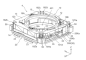
- FIG. 3 is a perspective view of an optical element driving device body included in the optical element driving device of the camera module
- 4 is a perspective view from a different direction of the main body of the optical element driving device shown in FIG. 3
- FIG. 5 is an exploded perspective view of the main body of the optical element driving device shown in FIGS. 3 and 4
- FIG. 6 is an exploded perspective view of the OIS movable portion shown in FIG. 5;
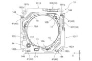
- FIG. 5 is a plan view of the main body of the optical element driving device shown in FIGS. 3 and 4;
- FIG. 4 is a plan view showing a positional relationship between an OIS fixed portion and an AF movable portion;
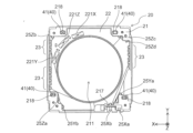
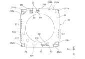
- FIG. 4 is a plan view of an OIS fixing portion; It is a bottom view of an OIS fixing
- FIG. 15B is a perspective view of the automobile shown in FIG. 15A as viewed obliquely from the rear;
- FIG. 1A and 1B are diagrams showing a smartphone M (an example of a camera-equipped device) equipped with a camera module A according to the present embodiment.
- 1A is a front view of the smartphone M
- FIG. 1B is a rear view of the smartphone M.
- FIG. 1A is a front view of the smartphone M
- FIG. 1B is a rear view of the smartphone M.
- Smartphone M has a dual camera consisting of two rear cameras OC1 and OC2.
- the camera module A is applied to the rear cameras OC1 and OC2.
- Camera module A has an AF function and a shake correction function (hereinafter referred to as "OIS function", OIS: Optical Image Stabilization).
- OIS function Optical Image Stabilization
- the camera module A uses the AF function to automatically adjust the focus when shooting a subject, and the OIS function to optically correct the shake (vibration) that occurs during shooting to shoot images without image blur. can do.
- FIG. 2 is a perspective view showing the camera module A and the imaging section 5.
- FIG. 3 and 4 are perspective views of the optical element driving device main body 4 included in the optical element driving device 1 of the camera module A shown in FIG.
- FIG. 4 is a diagram of the optical element driving device main body 4 shown in FIG. 3 rotated by 180° around the Z-axis.
- this embodiment will be described using an orthogonal coordinate system (X, Y, Z).
- the drawings to be described later are also shown in a common orthogonal coordinate system (X, Y, Z).
- the camera module A when photographing is performed by the smartphone M, the camera module A is mounted so that the X direction is the up-down direction (or the left-right direction), the Y direction is the left-right direction (or the up-down direction), and the Z direction is the front-back direction. . That is, the Z direction is the optical axis direction, and in FIGS. 2 to 4, the upper side (+Z side) is the light receiving side in the optical axis direction, and the lower side ( ⁇ Z side) is the imaging side in the optical axis direction.
- optical axis orthogonal direction the X direction and the Y direction orthogonal to the Z axis
- XY plane the XY plane
- optical axis orthogonal plane the direction orthogonal to the optical axis
- the camera module A includes an optical element driving device 1 that realizes an AF function and an OIS function, a lens unit 2 configured by housing a lens in a cylindrical lens barrel, and an image formed by the lens unit 2.
- An imaging unit 5 and the like are provided for capturing an image of the subject. That is, the optical element driving device 1 is a so-called lens driving device that drives the lens portion 2 as an optical element.
- the optical element driving device main body 4 is covered with a cover 3 on the outside.
- the cover 3 is a lidded quadrangular cylinder having a rectangular shape in a plan view seen from the optical axis direction. In this embodiment, the cover 3 has a square shape in plan view.
- the cover 3 has a substantially circular opening 301 on its upper surface.
- the lens unit 2 is accommodated in the opening 401 of the optical element driving device main body 4 and faces the outside through the opening 301 of the cover 3. For example, as it moves in the optical axis direction, the lens unit 2 moves toward the light receiving side of the opening surface of the cover 3 in the optical axis direction.
- the inner wall of the cover 3 is fixed to the base 21 (see FIG. 5 which will be described later) of the OIS fixing portion 20 of the optical element driving device main body 4 by, for example, adhesion, and the OIS movable portion 10 etc. (FIG. ).
- the cover 3 has a member that blocks electromagnetic waves from the outside of the optical element driving device 1, for example, a shield member made of a magnetic material.
- the imaging unit 5 is arranged on the imaging side of the optical element driving device 1 in the optical axis direction.
- the imaging unit 5 has, for example, an image sensor substrate 501 , an imaging device 502 mounted on the image sensor substrate 501 , and a control unit 503 .
- the imaging device 502 is configured by, for example, a CCD (charge-coupled device) image sensor, a CMOS (complementary metal oxide semiconductor) image sensor, or the like, and captures an object image formed by the lens unit 2 .
- CCD charge-coupled device
- CMOS complementary metal oxide semiconductor
- the control unit 503 is composed of, for example, a control IC, and controls driving of the optical element driving device 1 .
- the optical element driving device 1 is mounted on the image sensor substrate 501 and mechanically and electrically connected.
- the control unit 503 may be provided on the image sensor substrate 501, or may be provided on a camera-equipped device (in this embodiment, the smart phone M) on which the camera module A is mounted.
- FIG. 5 is an exploded perspective view of the main body 4 of the optical element driving device.
- FIG. 6 is an exploded perspective view of the OIS movable portion 10.
- FIG. FIG. 7 is a plan view of the main body 4 of the optical element driving device. The optical element driving device main body 4 will be described with reference to FIGS. 5 to 7 as well.
- the optical element driving device main body 4 includes an OIS movable portion 10, an OIS fixed portion 20, an OIS driving portion 30, an OIS supporting portion 40, and an OIS biasing member 50, as shown in FIG.
- the OIS movable portion 10 is a portion that can hold the lens portion 2 and that swings within a plane perpendicular to the optical axis during shake correction.
- the OIS movable section 10 has an AF section 11, a second stage 14, and an OIS support section 40 (Y-direction reference ball 42) (see FIG. 6).
- the AF section 11 has an AF movable section 12, a first stage 13, an AF drive section 15, and AF support sections 16A and 16B (see FIGS. 5 and 6).
- the OIS fixing part 20 has a base 21 and an OIS supporting part 40 (X-direction reference ball 41), as shown in FIG.
- the OIS fixing section 20 is arranged at a position separated from the OIS movable section 10 in the optical axis direction via the OIS support section 40, and the OIS support section 40 allows the OIS movable section 10 to swing in the direction perpendicular to the optical axis. This is the supporting part.
- the OIS movable section 10 is spaced apart from the base 21 in the optical axis direction via the X-direction reference ball 41 , and the base 21 is connected to the OIS movable section 10 via the X-direction reference ball 41 . is swingably supported.
- the OIS movable part 10 and the OIS fixed part 20 are elastically connected by the OIS biasing member 50 so as to be biased toward each other, in other words, to hold the OIS support part 40 sandwiched therebetween. (see FIGS. 3-5).
- the OIS biasing member 50 is made of a conductive material. Although the details will be described later, the OIS biasing member 50 also functions as a connection member that forms a conductive path between a circuit for driving the lens unit 2 and the like and a circuit on the OIS fixing unit 20 side.
- the OIS biasing members 50 are arranged at the four corner portions (corner portions) in plan view of the optical element driving device main body 4 (see FIGS. 3 and 4).
- the OIS driving section 30 has a first OIS driving section 30X that drives the OIS movable section 10 in the X direction, and a second OIS driving section 30Y that drives the OIS movable section 10 in the Y direction.
- the entire OIS movable section 10 including the AF section 11 moves as a movable body with respect to movement in the X direction.
- the base 21 of the OIS fixing portion 20 constitutes a fixed body
- the X direction reference ball 41 functions as an OIS support portion 40 that supports the OIS movable portion 10 so as to be swingable in the X direction. do.
- the AF section 11 moves as a movable body with respect to movement in the Y direction.
- the second stage 14 constitutes a fixed body together with the base 21, and the Y direction reference ball 42 functions as an OIS support portion 40 that supports the AF portion 11 so as to be swingable in the Y direction. do.
- [OIS fixing part] 9 is a plan view of the OIS fixing portion 20.
- FIG. 10 is a bottom view of the OIS fixing portion 20.
- FIG. The OIS fixing unit 20 will be described with reference to FIGS. 9 and 10 as well.
- the OIS fixing section 20 has a base 21, a substrate 22, a first OIS driving section 30X, and an OIS supporting section 40 (X-direction reference ball 41) (see FIG. 5).
- the base 21 is formed of, for example, polyarylate (PAR), a PAR alloy (for example, PAR/PC) obtained by mixing a plurality of resin materials including PAR, or a molding material made of liquid crystal polymer.
- the base 21 is a rectangular member in plan view and has a circular opening 211 in the center.
- the base 21 has an OIS motor fixing portion 217 on which the first OIS driving portion 30X is arranged.
- the OIS motor fixing portion 217 is provided, for example, near one corner of the base 21, protrudes from the base 21 toward the light receiving side in the optical axis direction, and has a shape capable of holding the first OIS driving portion 30X. (see Figure 5).
- the base 21 also has an X-direction reference ball holding portion 218 that holds the X-direction reference ball 41 that constitutes the OIS support portion 40 .
- the X-direction reference ball 41 is sandwiched between the X-direction reference ball holding portion 218 and the X-direction reference ball holding portion 144 (see FIG. 11 described later) of the second stage 14 facing each other in the Z direction.
- the X-direction reference ball holding portion 218 and the X-direction reference ball holding portion 144 are recesses having rectangular openings extending in the X direction.
- the X-direction reference ball holding portion 218 and the X-direction reference ball holding portion 144 have, for example, a substantially V-shaped (tapered) cross-sectional shape or a substantially U-shaped cross section so that the groove width becomes narrower toward the bottom surface of the recess. formed to be
- the groove formed by the recess having the cross-sectional shape described above is formed parallel to the X direction, so that the X direction reference ball holding portion 218 and the X direction reference ball holding portion 144 are sandwiched.
- the ball 41 can roll in the X direction within the recess. That is, the base 21 supports the OIS movable part 10 (second stage 14) through the X-direction reference ball 41 so as to be movable in the X-direction.
- the X-direction reference ball holding portion 218 and the X-direction reference ball holding portion 144 are arranged at four corners of the rectangular base 21 and the second stage 14, and the OIS movable portion 10 (second stage 14) has four It is supported on the base 21 by the X-direction reference ball 41, that is, at four points. In this way, the X-direction reference ball 41 is sandwiched by multi-point contact, so that it rolls stably in the Y-direction.
- the OIS movable section 10 (second stage 14) should be supported by the base 21 at least at three points or more.
- the X-direction reference ball holding portion 218 and the X-direction reference ball holding portion 218 and The X-direction reference ball holding portion 144 may be arranged.
- a plurality of terminals 23 and power supply lines 25Xa, 25Xb, 25Ya, 25Yb, 25Za, 25Zb, 25Zc, and 25Zd are arranged on the outer edge of the base 21 (see FIGS. 9 and 10).
- the terminals 23 are embedded in the base 21 by, for example, insert molding, with one end of each terminal exposed from the top surface of the base 21 (see FIG. 9) and the other end exposed from the bottom surface of the base 21. (see FIG. 10).
- the terminal 23 is a terminal for power supply and signal to driver ICs 221X, 221Y, and 221Z which drive the first OIS driving section 30X, the second OIS driving section 30Y, and the AF driving section 15, respectively.
- the power supply wirings 25Xa and 25Xb are formed so as to be exposed on the upper surface of the base 21 from the inner end to the outer end in the outer edge portion of the base 21 (see FIG. 9).
- the power supply wirings 25Ya and 25Yb have inner ends exposed on the top surface of the base 21 (see FIG. 9) and outer ends exposed on the bottom surface of the base 21 at the corners that are the outer edge portions of the base 21. (see FIG. 10).
- the power supply wirings 25Za, 25Zb, 25Zc, and 25Zd have inner ends exposed on the upper surface of the base 21 at corners, which are outer edge portions of the base 21 (see FIG. 9), and outer ends of the base 21. (see FIG. 10).
- the inner ends of the power supply wirings 25Xa and 25Xb are connected to the substrate 22 and connected to the driver IC 221X via a booster section 60, which will be described later. Outer ends of the power supply lines 25Xa and 25Xb are connected to the first OIS driver 30X. Further, the inner ends of the power supply wirings 25Ya and 25Yb are connected to the substrate 22 and connected to the driver IC 221Y via the boosting section 60, which will be described later. The outer ends of the power supply wirings 25Ya and 25Yb are connected to the second OIS driving section 30Y via the OIS biasing member 50 and the power supply wirings 18Ya and 18Yb.
- the inner ends of the power supply wirings 25Za, 25Zb, 25Zc, and 25Zd are connected to the substrate 22 and connected to the driver IC 221Z via a boosting section 60, which will be described later.
- the outer ends of the power supply wirings 25Za, 25Zb, 25Zc and 25Zd are connected to the two AF drive units 15 via the OIS biasing member 50 and the power supply wirings 18Za, 18Zb, 18Zc and 18Zd.
- the driver IC 221X is a 1-channel driver IC that controls driving of one drive unit
- the driver IC 221Y is also a similar 1-channel driver IC
- the driver IC 221Z is a two-channel driver IC that controls driving of the two drive units.
- the number of channels in the driver ICs 221X, 221Y, and 221Z can be appropriately changed according to the number of drive units to be driven.
- the substrate 22 is arranged on the light receiving side of the base 21 in the optical axis direction.
- the substrate 22 is electrically connected to terminals 23 exposed on the upper surface of the base 21, and the terminals 23 are connected to the driver ICs 221X, 221Y, 221Z, etc. via wiring (not shown) formed on the substrate 22.
- the driver ICs 221X, 221Y, and 221Z are connected to power supply wirings 25Xa, 25Xb, 25Ya, 25Yb, 25Za, 25Zb, 25Zc, and 25Zd via wiring (not shown) formed on the substrate 22 .
- the power supply lines 25Xa, 25Xb, 25Ya, 25Yb, 25Za, 25Zb, 25Zc, and 25Zd are connected to the first OIS driving section 30X, the second OIS driving section 30Y, and the AF driving section 15 as described above.
- the driver ICs 221X, 221Y, and 221Z are arranged on the light-receiving side of the substrate 22 in the optical axis direction, and each have a magnetic sensor (not shown).
- These magnetic sensors are composed of, for example, Hall elements, TMR (Tunnel Magneto Resistance) sensors, etc., and detect magnetic fields generated by magnets 17X, 17Y, and 17Z (magnets) described later, and detect X, Y, and A position in the Z direction is detected magnetically.
- the driver ICs 221X, 221Y, and 221Z are provided in a region where the AF drive section 15, AF support sections 16A, 16B, first OIS drive section 30X, and second OIS drive section 30Y are not arranged (see FIG. 5). reference). That is, it is provided in a region near one corner of the rectangular base 21 in plan view (see FIG. 9). As a result, the driver ICs 221X, 221Y, and 221Z can be concentrated in one area, and the space inside the optical element driving device main body 4 can be effectively utilized.
- a magnet 17X is arranged on the bottom side of the second stage 14 that moves in the X direction, and the driver IC 221X and the magnet 17X are arranged to face each other.
- the X-direction position of the second stage 14, that is, the X-direction position of the OIS movable section 10 is detected by an X-direction position detection section including the driver IC 221X and the magnet 17X.
- a magnet 17Y is arranged on the bottom side of the first stage 13 that moves in the Y direction, and the driver IC 221Y and the magnet 17Y are arranged so as to face each other.
- a Y-direction position detection unit including the driver IC 221Y and the magnet 17Y detects the Y-direction position of the first stage 13, that is, the Y-direction position of the OIS movable unit 10.
- a magnet 17Z is arranged on the bottom side of the AF movable portion 12 that moves in the Z direction, and the driver IC 221Z and the magnet 17Z are arranged so as to oppose each other.
- the Z-direction position of the AF movable section 12 is detected by the Z-direction position detection section including the driver IC 221Z and the magnet 17Z.
- an optical sensor such as a photoreflector may be used to detect the positions of the OIS movable section 10 in the X and Y directions and the position of the AF movable section 12 in the Z direction.
- the optical element driving device 1 ultrasonic motors including piezoelectric elements are used as the AF driving section 15, the first OIS driving section 30X, and the second OIS driving section 30Y from the viewpoint of miniaturization. Since a relatively large drive voltage is required to drive the ultrasonic motor, this embodiment includes a booster 60 that boosts the input voltage to a desired voltage.
- the boosting section 60 is connected between the driver IC 221X and the first OIS driving section 30X, between the driver IC 221Y and the second OIS driving section 30Y, and between the driver IC 221Z and the AF driving section 15.
- the drive circuit is configured to The driver ICs 221X, 221Y, and 221Z are arranged on the upper surface side (light receiving side in the optical axis direction) of the substrate 22 (see FIG. 9). side) (see FIG. 10).
- the driver ICs 221X, 221Y, and 221Z each have Hall elements as magnetic sensors.
- the driver ICs 221X, 221Y, 221Z output drive currents according to the positions of the magnets 17X, 17Y, 17Z detected by the respective Hall elements.
- a series resonance circuit having an inductor, a circuit in which a capacitor is connected in parallel to the series resonance circuit, or the like can be used as the booster section 60 .
- the drive currents output from the driver ICs 221X, 221Y, and 221Z are boosted in voltage by the booster 60 and supplied to the first OIS drive section 30X, the second OIS drive section 30Y, and the AF drive section 15, respectively. Accordingly, the first OIS driving section 30X and the second OIS driving section 30Y are driven to perform shake correction, and the AF driving section 15 is driven to perform autofocus.
- the optical element driving device 1 has two AF driving units 15, a first OIS driving unit 30X and a second OIS driving unit 30Y, and therefore has four sets of boosting units 60.
- the boosting section 60 is arranged at a position away from the magnets 17X, 17Y, 17Z and the driver ICs 221X, 221Y, 221Z.
- the inductor of the booster section 60 has magnetic performance, but the arrangement described above can suppress the magnetic influence of the inductor of the booster section 60 on the magnets 17X, 17Y, 17Z and the driver ICs 221X, 221Y, 221Z. .
- magnets 17X, 17Y, and 17Z arranged on the light-receiving side of the base 21 in the optical axis direction are arranged on the lower left side of the figure.
- the boosting section 60 is arranged at a position away from the magnets 17X, 17Y and 17Z, at least at a position not facing the magnets 17X, 17Y and 17Z.
- the boosting section 60 is arranged on the bottom surface side of the substrate 22, which is the surface that does not face the magnets 17X, 17Y, and 17Z.
- an opening 219 penetrating through the base 21 is provided. be positioned.
- the booster section 60 By arranging the booster section 60 on the bottom side of the substrate 22, it is possible to secure the distance (distance in the Z direction) between the inductor of the booster section 60 and the magnets 17X, 17Y, and 17Z. can suppress the magnetic influence of As a result, it is possible to suppress the influence on the detectability of the magnetic sensor.
- the OIS driving section 30 is an actuator that moves the OIS movable section 10 in the X direction and the Y direction. Specifically, the OIS driving section 30 includes a first OIS driving section 30X that moves the entire OIS movable section 10 in the X direction, and a second OIS driving section 30X that moves a part of the OIS movable section 10 (the AF section 11) in the Y direction. and a portion 30Y.
- first OIS driving section 30X and the second OIS driving section 30Y are arranged in different directions, they have the same components, so the same reference numerals are given to the same components, and refer to FIG. and explain.
- the first OIS drive section 30X and the second OIS drive section 30Y have ultrasonic motors that serve as drive sources for moving the OIS movable section 10.
- the first OIS driving section 30X is fixed to the OIS motor fixing section 217 along the X direction of the base 21 .
- the second OIS driving section 30Y is fixed to the OIS motor fixing section 134 of the first stage 13 along the Y direction. That is, the first OIS driving unit 30X and the second OIS driving unit 30Y are arranged along the X-direction side surface 101X and the Y-direction side surface 101Y that are orthogonal to each other in the OIS movable unit 10 (see FIGS. 3 to 5, etc.). ).
- the first OIS drive section 30X and the second OIS drive section 30Y have an OIS resonance section 31 that is a resonance section, an OIS piezoelectric element 32 that is a piezoelectric element, and an OIS power transmission section 34 that is a power transmission section.
- the driving force of the OIS drive section 30 is transmitted to other members via the OIS power transmission section 34 .
- the first OIS driving section 30X is connected to the second stage 14 via the OIS power transmission section 34, and the driving force thereof is transmitted.
- the second OIS driving section 30Y is connected to the second stage 14 via the OIS power transmission section 34, and the driving force thereof is transmitted.
- the OIS resonance section 31 constitutes an active element
- the OIS power transmission section 34 constitutes a passive element.
- the OIS resonance part 31 is made of a conductive material, is sandwiched between OIS piezoelectric elements 32 to be described later, resonates with vibrations of the OIS piezoelectric elements 32, and converts vibrational motion into linear motion.
- the OIS resonator 31 is formed by, for example, laser processing, etching processing, press processing, or the like of a metal plate.
- the OIS resonance section 31 of the first OIS drive section 30X is fixed to the OIS motor fixing section 217 (base 21 side) with, for example, a rivet, an adhesive, or the like.
- the OIS resonance section 31 of the second OIS drive section 30Y is fixed to the OIS motor fixing section 134 (on the first stage 13 side) with, for example, a rivet, an adhesive, or the like.
- the OIS piezoelectric element 32 is, for example, a plate-like element made of ceramic material, and generates vibration by applying a high-frequency voltage.
- the two OIS piezoelectric elements 32 are bonded together so as to sandwich the OIS resonator 31 .
- the OIS piezoelectric element 32 of the first OIS driving section 30X is electrically connected to the above-described power supply wirings 25Xa and 25Xb by, for example, electrode members (not shown).
- the OIS piezoelectric element 32 of the second OIS drive unit 30Y is electrically connected to the above-described power supply wirings 18Ya and 18Yb by, for example, electrode members (not shown) or the like. Such a connection allows a voltage to be applied to the OIS piezoelectric element 32, and the application of the voltage causes the OIS piezoelectric element 32 to vibrate.
- the OIS resonance section 31 described above has at least two resonance frequencies, and deforms with different behavior for each resonance frequency.
- the OIS resonator 31 is configured to deform in different behaviors with respect to two resonance frequencies.
- the different behaviors are the behavior of advancing the OIS power transmission section 34 in the X direction or the Y direction and the behavior of retreating. Therefore, by vibrating the OIS piezoelectric element 32 at a desired resonance frequency, the OIS power transmission section 34 can be moved forward or backward in the X direction or the Y direction.
- the OIS power transmission section 34 is a chucking guide extending in the X direction or the Y direction, one end of which is in contact with the OIS resonance section 31 and the driving force from the OIS resonance section 31 is transmitted.
- a stage fixing portion 35 which is the other end of the OIS power transmission portion 34 , is connected to the second stage 14 .
- the stage fixing portion 35 of the first OIS driving portion 30X is fixed to the OIS chucking guide fixing portion 145X of the second stage 14 .
- the stage fixing portion 35 of the second OIS driving portion 30Y is fixed to the OIS chucking guide fixing portion 145Y of the second stage 14 .
- the second OIS drive section 30Y is fixed to the first stage 13 (on the side of the OIS movable section 10) via the OIS motor fixing section 134, and connected to the second stage 14 via the OIS power transmission section 34. It is The second OIS driving unit 30Y is driven during shake correction in the Y direction, and drives the first stage 13 with respect to the second stage 14 so as to move in the Y direction. Note that the second OIS driving section 30Y moves together with the first stage 13 (OIS movable section 10) when the first OIS driving section 30X performs shake correction in the X direction.
- the first OIS driving section 30X is fixed to the base 21 (on the OIS fixing section 20 side) via the OIS motor fixing section 217 and connected to the second stage 14 via the OIS power transmission section 34 .
- the first OIS driving section 30X is driven during shake correction in the X direction, and drives the second stage 14 to move in the X direction with respect to the base 21 (OIS fixing section 20). Since the first OIS driving section 30X moves the second stage 14 in the X direction with respect to the base 21 (OIS fixing section 20), it is not affected by the shake correction in the Y direction by the second OIS driving section 30Y.
- the movement by one OIS drive unit 30 is not hindered by the structure of the other OIS drive unit 30. Therefore, it is possible to prevent the rotation of the OIS movable part 10 around the Z axis, and it is possible to precisely swing the OIS movable part 10 within the XY plane.
- the OIS support section 40 supports the OIS movable section 10 so as to be swingable in the direction perpendicular to the optical axis with respect to the OIS fixed section 20 while being spaced apart in the optical axis direction.
- the OIS support section 40 has four X-direction reference balls 41 interposed between the OIS movable section 10 (second stage 14) and the base 21 (see FIG. 5).
- the OIS support section 40 has four Y-direction reference balls 42 interposed between the first stage 13 and the second stage 14 in the OIS movable section 10 (see FIG. 6).
- the four X-direction reference balls 41 can roll in the X direction, and the direction in which they can roll is restricted to the X direction.
- the four Y-direction reference balls 42 can roll in the Y direction, and the direction in which they can roll is restricted to the Y direction.
- OIS biasing member 50 are arranged at four corners (corners) of the rectangular OIS movable portion 10 and the OIS fixed portion 20, respectively.
- the OIS biasing member 50 is composed of, for example, an extension coil spring, and connects the OIS movable section 10 and the OIS fixed section 20 .
- the end portion of the OIS biasing member 50 on the imaging side in the optical axis direction is connected to the power supply wirings 25Ya, 25Yb, 25Za, 25Zb, 25Zc, and 25Zd exposed from the corners of the bottom surface of the base 21 (FIG. 10). ).
- the light-receiving side end in the optical axis direction is connected to the power supply wirings 18Ya, 18Yb, 18Za, 18Zb, 18Zc, and 18Zd of the first stage 13 (see FIGS. 3 and 4).
- the OIS biasing member 50 receives a tensile load when the OIS movable part 10 and the OIS fixed part 20 are connected, and acts so that the OIS movable part 10 and the OIS fixed part 20 come closer to each other. That is, the OIS movable section 10 is held so as to be able to swing within the XY plane while being biased toward the imaging side in the optical axis direction (pressed against the base 21) by the OIS biasing member 50. there is As a result, the OIS movable portion 10 can be held in a stable state without rattling.
- two OIS urging members 50 are arranged radially outward of the two AF driving units 15 so that the AF driving units 15 can be stably driven.
- the OIS biasing member 50 is made of a conductive material and functions as a power supply line (conductive path) to the AF driving section 15 and the second OIS driving section 30Y.
- the OIS biasing member 50 is arranged in notches (reference numerals omitted) obtained by notching the four corners (corner portions) of the first stage 13 and the second stage 14 (FIGS. 3 and 4). ). Since the notches are formed in the first stage 13 and the second stage 14, the OIS biasing member 50 can be arranged without increasing the size of the base 21, thereby suppressing an increase in the size of the device. , the size of the optical element driving device 1 can be reduced.
- [OIS moving part] 11 is a bottom view of the OIS movable part 10.
- FIG. The OIS movable section 10 will be described with reference to FIG. 11 as well.
- the OIS movable section 10 is configured to be able to hold the lens section 2 (see FIG. 2), and has an AF section 11, a second stage 14, etc., as shown in FIGS.
- the AF section 11 also includes an AF movable section 12, a first stage 13, an AF drive section 15, AF support sections 16A and 16B, and the like.
- the OIS movable section 10 is configured by stacking a first stage 13 and a second stage 14 on the base 21 of the OIS fixed section 20 .
- the OIS movable section 10 is configured to be movable in the direction orthogonal to the optical axis together with the AF movable section 12 by the OIS driving section 30 (the first OIS driving section 30X and the second OIS driving section 30Y).
- the entire OIS movable section 10 including the first stage 13 and the second stage 14 is a movable body.
- the second stage 14 functions as a fixed body together with the OIS fixed section 20, and only the AF section 11 (AF movable section 12 and first stage 13) functions as a movable body.
- the first stage 13 also functions as an AF fixed section that supports the AF movable section 12 .
- FIG. 8 is a plan view showing the positional relationship between the OIS fixing section 20 and the AF movable section 12. As shown in FIG. 13 is a bottom view of the AF movable section 12. FIG. The AF movable section 12 will be described with reference to FIGS. 8 and 13 as well. 8 shows the OIS fixed part 20 and the AF movable part 12 in order to show the positional relationship between the OIS fixed part 20 and the AF movable part 12. The first stage 13 and the second stage 14 are shown in FIG. not shown.
- the AF movable section 12 is a lens holder capable of holding the lens section 2 (see FIG. 2), and is configured to be movable in the optical axis direction (Z direction) by the AF driving section 15 while holding the lens section 2. ing.
- the AF movable portion 12 is moved in the optical axis direction, for example, during focusing in the AF function.
- the AF movable section 12 is arranged radially inward (on the side of the lens section 2) with a distance from the first stage 13 (AF fixed section), and is supported by the first stage 13 via AF support sections 16A and 16B. (see FIG. 5).
- the AF movable part 12 is made of, for example, polyarylate (PAR), a PAR alloy obtained by mixing a plurality of resin materials including PAR, liquid crystal polymer, or the like.
- PAR polyarylate
- PAR alloy obtained by mixing a plurality of resin materials including PAR, liquid crystal polymer, or the like.
- the AF movable section 12 has a lens accommodating section 121 having a cylindrical opening inside.
- the lens portion 2 is fixed to the inner peripheral surface 121a of the lens housing portion 121 by, for example, adhesion (see FIG. 6).
- the AF movable portion 12 has a protruding portion 123 protruding radially outward from a portion of the outer peripheral surface 121b of the lens accommodating portion 121 and extending toward the imaging side in the optical axis direction.
- a magnet 17Z for detecting the Z position is provided inside the projecting portion 123.
- the magnet 17Z is arranged at a position facing the Z-position driver IC 221Z (magnetic sensor) of the substrate 22 in the optical axis direction (see FIG. 8, etc.).
- the projecting portion 123 is inserted into an insertion hole 132 of the first stage 13, which will be described later, and moves along the insertion hole 132 when the AF movable portion 12 moves in the Z direction.
- a first rail member 161 that constitutes the AF support portions 16A and 16B is attached on the outer peripheral surface 121b of the lens housing portion 121.
- the first rail members 161 are attached to three locations on the outer peripheral surface 121b of the lens accommodating portion 121.
- the AF movable portion 12 is supported movably in the Z direction by AF support portions 16A and 16B having first rail members 161 and the like.
- the AF support portions 16A and 16B having the first rail member 161 will be described later.
- the lens accommodating section 121 is connected to the AF drive section 15 by an AF connection member (not shown).
- the AF movable section 12 is driven by the AF driving section 15 via the AF connection member connected to the lens accommodating section 121 to move in the Z direction.
- the AF driving section 15 is an actuator that moves the AF movable section 12 in the Z direction.
- the AF driving section 15 has an ultrasonic motor that serves as a driving source for moving the AF movable section 12, similarly to the OIS driving section 30. As shown in FIG.
- the AF drive unit 15 has a different size, shape, etc., but basically has the same configuration as the OIS drive unit 30, and includes an AF resonance unit as a resonance unit, an AF piezoelectric element as a piezoelectric element, and a power It has an AF power transmission section which is a transmission section. Therefore, as for the AF drive unit 15, illustration of its constituent elements is omitted, and redundant description is also omitted.
- the AF drive unit 15 is fixed to the inner peripheral surface 131a of the opening 131 of the first stage 13 with, for example, a rivet, an adhesive, or the like.
- the driving force of the AF drive section 15 fixed to the inner peripheral surface 131a is transmitted to the AF movable section 12 via the AF power transmission section and the AF connection member.
- the AF resonance section constitutes an active element
- the AF power transmission section constitutes a passive element.
- a pair of AF drive units 15 are provided in the present embodiment. Although the arrangement of the AF drive units 15 will be described later with reference to FIG. 14 , the pair of AF drive units 15 are arranged at diagonal positions of the OIS movable unit 10 .
- [1st stage] 12 is a bottom view of the AF movable section 12 and the first stage 13. FIG. Also referring to FIG. 12, the first stage 13 will be described.
- the first stage 13 supports the AF movable section 12 via AF support sections 16A and 16B.
- the second stage 14 is arranged on the imaging side of the first stage 13 in the optical axis direction with a Y-direction reference ball 42 interposed therebetween.
- the first stage 13 moves in the X and Y directions during shake correction, and the second stage 14 moves only in the X direction during shake correction.
- the first stage 13 is a member having a substantially rectangular shape in a plan view seen from the optical axis direction, and is made of liquid crystal polymer, for example.
- the first stage 13 has a substantially circular opening 131 in a portion corresponding to the AF movable section 12 .
- An insertion hole 132 corresponding to the projecting portion 123 of the AF movable portion 12 is formed in the first stage 13 (see FIG. 6).
- the first stage 13 has a Y-direction reference ball holding portion 133 that holds the Y-direction reference ball 42 constituting the OIS support portion 40 on its lower surface (see FIG. 12).
- the Y-direction reference ball 42 is sandwiched between the Y-direction reference ball holding portion 133 and the Y-direction reference ball holding portion 143 of the second stage 14 facing in the Z direction (see FIG. 6).
- the Y-direction reference ball holding portion 133 and the Y-direction reference ball holding portion 143 are recesses having rectangular openings extending in the Y direction.
- the Y-direction reference ball holding portion 133 and the Y-direction reference ball holding portion 143 have, for example, a substantially V-shaped (tapered) or substantially U-shaped cross section so that the groove width becomes narrower toward the bottom surface of the recess. formed to be
- the groove formed by the concave portion having the above-described cross-sectional shape is formed parallel to the Y direction.
- the ball 42 can roll in the Y direction within the recess. That is, in the OIS movable section 10 , the second stage 14 supports the first stage 13 movably in the Y direction via the Y-direction reference ball 42 .
- the Y-direction reference ball holding portion 133 and the Y-direction reference ball holding portion 143 are arranged at the four corners of the rectangular first stage 13 and second stage 14.
- the first stage 13 holds four Y-direction reference balls. It is supported by the second stage 14 at 42, that is, at four points. In this way, the Y-direction reference ball 42 is sandwiched by multi-point contact, so that it rolls stably in the Y-direction.
- the first stage 13 may be supported by the second stage 14 at least three points.
- the Y-direction reference ball holders are placed at three points in total: two points on one side of the first stage 13 and second stage 14 and one point on the side opposite to the side.
- 133 and the Y-direction reference ball holding portion 143 may be arranged.
- the OIS motor fixing portion 134 on which the second OIS driving portion 30Y is arranged is recessed radially inward so that the second OIS driving portion 30Y can be arranged without protruding radially outward. (See Figure 6).
- the concave portion 137 in which the first OIS driving portion 30X is arranged is also formed so as to be concave inward in the radial direction.
- two AF motor fixing portions (reference numerals omitted) are provided at positions symmetrical with respect to the center of the opening 131.
- the AF drive units 15 are arranged and fixed to the respective motor fixing portions.
- Second rail members 164 and 165 that constitute the AF support portions 16A and 16B are attached to the inner peripheral surface 131a of the opening 131. As shown in FIG. Here, as an example, the second rail members 164 and 165 are attached to the inner peripheral surface 131a of the opening 131 at three locations. AF support portions 16A and 16B having second rail members 164 and 165 will be described later.
- a magnet 17Y for detecting the Y position is arranged on the bottom surface of one frame portion along the X direction (see FIG. 12).
- the magnet 17Y is magnetized in the Y direction.
- the driver IC 221Y having a magnetic sensor for detecting the Y position is arranged at a position facing the magnet 17Y in the optical axis direction (see FIGS. 8, 9, etc.).
- power supply wirings 18Ya, 18Yb, 18Za, 18Zb, 18Zc, and 18Zd are embedded in the first stage 13 by, for example, insert molding (see FIG. 6).
- the power supply wirings 18Ya, 18Yb, 18Za, 18Zb, 18Zc, and 18Zd are exposed from notches (reference numerals omitted) obtained by notching the four corners of the first stage 13, and the OIS biasing members 50 are attached to these portions. is connected.
- the power supply wirings 18Ya and 18Yb are formed inside the first stage 13 so as to extend from the notches at the four corners to the vicinity of the second OIS drive section 30Y to which power is to be supplied, and are connected to the second OIS drive section 30Y. Further, the power supply wirings 18Za and 18Zb are formed inside the first stage 13 so as to extend from the notches at the four corners to the vicinity of one AF driving section 15 to which power is to be supplied, and are connected to the AF driving section 15. there is In addition, the power supply wirings 18Zc and 18Zd are formed inside the first stage 13 so as to extend from the notches at the four corners to the vicinity of another AF drive unit 15 to which power is to be supplied, and are connected to the AF drive unit 15. It is
- power is supplied to the second OIS driving section 30Y that moves the first stage 13 in the Y direction through the power supply wirings 18Ya and 18Yb.
- power is supplied to the AF drive section 15 that moves the AF movable section 12 in the Z direction through the power supply wirings 18Za, 18Zb, 18Zc, and 18Zd.
- the second stage 14 is a member having a substantially rectangular shape in plan view seen from the optical axis direction, and is made of liquid crystal polymer, for example.
- the opening 141 of the second stage 14 is formed in a substantially rectangular shape (see FIG. 6).
- the concave portion 146 in which the second OIS driving portion 30Y is arranged is formed so as to be concave inward in the radial direction, similarly to the first stage 13.
- a cutout portion 147 in which the first OIS driving portion 30X is arranged is formed integrally with the cutout portion of the corner portion.
- the second stage 14 has a Y-direction reference ball holding portion 143 that holds the Y-direction reference ball 42 constituting the OIS support portion 40 on its upper surface.
- the Y-direction reference ball holding portion 143 may have the same configuration as the above-described Y-direction reference ball holding portion 133 arranged to face the Y-direction reference ball holding portion 143, so redundant description will be omitted here. .
- the second stage 14 has an X-direction reference ball holding portion 144 that holds the X-direction reference ball 41 constituting the OIS support portion 40 on its lower surface (see FIG. 11).
- the X-direction reference ball holding portion 144 may have the same configuration as the X-direction reference ball holding portion 218 arranged to face the X-direction reference ball holding portion 144, so redundant description will be omitted here as well. .
- a magnet 17X for detecting the X position is arranged on the bottom surface of one frame portion along the Y direction (see FIG. 11).
- magnet 17X is magnetized in the X direction.
- the driver IC 221X having the magnetic sensor for detecting the X position is arranged at a position facing the magnet 17X in the optical axis direction (see FIGS. 8, 9, etc.).
- the magnet 17X is arranged on the second stage 14 that moves in the X direction
- the magnet 17Y is arranged on the first stage 13 that moves in the Y direction (FIGS. 11 and 12).
- the first stage 13 moves, but the second stage 14 does not move, and the magnet 17X arranged on the second stage 14 does not move either. Therefore, the influence of the magnet 17Y is eliminated when the magnet 17X detects the position in the X direction, and the detection accuracy can be improved.
- the first rail member 161 is attached to the outer peripheral surface 121b of the lens housing portion 121 of the AF movable portion 12, and the second rail member 164 is attached to the inner peripheral surface 131a of the opening 131 of the first stage 13. , 165 are attached (see FIG. 6).
- a Z-direction reference ball 162 held by a retainer 163 is sandwiched between the first rail member 161 and the second rail member 164 to form the AF support portion 16A.
- a Z-direction reference ball 162 held by a retainer 163 is sandwiched between the first rail member 161 and the second rail member 165 to form the AF support portion 16B.
- the AF support section 16A has a first rail member 161, a Z-direction reference ball 162, a retainer 163 and a second rail member 164.
- the AF support portion 16B has a first rail member 161, a Z-direction reference ball 162, a retainer 163, and a second rail member 165.
- the first rail member 161 is attached to a clamping surface (reference numerals omitted) that rotatably clamps the Z-direction reference ball 162 when the first rail member 161 moves in the Z direction together with the AF movable section 12, and to the outer peripheral surface 121b of the lens housing section 121. and a claw portion (not shown).
- the clamping surface is a curved surface extending in the optical axis direction, and is curved such that the central portion thereof is recessed inside the lens accommodating portion 121 in plan view.
- the claw portions extend toward the inner side of the lens accommodating portion 121 and are arranged at two locations sandwiching the holding surface.
- the outer peripheral surface 121b of the lens accommodating portion 121 is formed with an insertion groove (reference numerals omitted) into which the claw portion is inserted.
- the first rail member 161 is attached to the outer peripheral surface 121b of the lens accommodating portion 121 by inserting the claw portion into the insertion groove and fixing it.
- the second rail member 164 also has a clamping surface (reference numeral omitted) that rotatably clamps the Z-direction reference ball 162 .
- the clamping surface is a curved surface extending in the optical axis direction, and the central portion thereof is curved so as to be recessed outward with respect to the outer peripheral surface 121b of the lens accommodating portion 121 in plan view.
- the second rail member 164 is arranged in a groove (not numbered) formed in the inner peripheral surface 131a of the opening 131, and fixed to the groove by, for example, a bonding method such as an adhesive.
- the second rail member 165 includes a fixed portion (not shown) fixed to a recess (not shown) formed in the inner peripheral surface 131a of the opening 131, and a biasing force contacting the Z-direction reference ball 162 to apply a biasing force. part (reference numeral omitted).
- the inside of the applying portion serves as a holding surface (reference numerals omitted) that rotatably holds the Z-direction reference ball 162 .
- the clamping surface is a curved surface extending in the optical axis direction, and the central portion thereof is curved so as to be recessed outward with respect to the outer peripheral surface 121b of the lens accommodating portion 121 in plan view.
- the applicator is connected to two deformation sections arranged to sandwich the applicator.
- the deforming portion is formed in a meandering shape, and the deforming portions arranged at two locations are arranged so as to be line-symmetrical with the applying portion interposed therebetween.
- the deformable portion formed in this manner is elastically deformable, and transmits a restoring force generated by elastic deformation to the applying portion as an urging force. That is, the second rail member 165 functions as an elastic member.
- the retainer 163 holds two Z-direction reference balls 162, for example.
- the two Z-direction reference balls 162 are arranged side by side along the optical axis direction by the retainer 163, are positioned in the optical axis direction, and are held at a constant distance from each other.
- the retainer 163 may have three or more Z-direction reference balls 162 (balls), but if it has two balls, the diameter of the balls should be larger than if it has three or more balls. can reduce the rolling resistance of the ball.
- two AF support portions 16A and one AF support portion 16B are arranged. movably supported.
- the AF support portions 16A and 16B are arranged in at least three dispersed positions in the circumferential direction on the inner peripheral surface 131a of the opening 131 of the first stage 13 .
- the angles between the AF support parts 16A and 16B are arranged at intervals of 120°, but this angle can be changed as appropriate.
- the AF support portions 16A and 16B may be dispersedly arranged at four or more points on the inner peripheral surface 131a of the opening 131.
- the three-point support Preferably, they are placed at multiples of 3, such as 6 or 9, to provide additional support between them.
- the Z-direction reference ball 162 is configured to be pressed and urged toward the first rail member 161 by the second rail members 164 and 165.
- the Z-direction reference ball 162 is configured to contact the first rail member 161 and press and urge it in the direction toward the inside of the opening 131 .
- the direction of the pressing forces F1 to F3 with which the Z-direction reference ball 162 presses the first rail member 161 is a point located inside the opening 131 when viewed from the optical axis direction. (see dashed-dotted and double-dotted lines).
- the directions of the pressing forces F1 to F3 are desirably directed toward the center of the opening 131 (the position of the optical axis OA).
- the AF support portions 16A and 16B and the AF drive portion 15 are arranged at different locations.
- a total of three AF support sections 16A and 16B and a total of two AF driving sections 15 are arranged. More specifically, one AF driving section 15 is arranged between the one AF supporting section 16A and the AF supporting section 16B, and the other AF driving section 15 is arranged between the other AF supporting section 16A and the AF supporting section 16B.
- a portion 15 is arranged.
- the AF drive units 15 are arranged separately in the circumferential direction on the inner peripheral surface 131a of the opening 131, similarly to the AF support units 16A and 16B.
- the AF drive unit 15 is arranged at two locations that are point-symmetrical with respect to the center of the opening 131, which are different from the locations where the AF support units 16A and 16B are arranged.
- the first stage 13 moves the AF movable portion 12 through the AF support portions 16A and 16B. It can be stably supported.
- the Z-direction reference balls 162 of the AF support portions 16A and 16B are configured to abut against the first rail member 161 and press and urge the lens accommodating portion 121 inward. For this reason, the AF movable portion 12 is supported so as to be movable in the optical axis direction while pressing and urging the AF movable portion 12 toward the inside of the lens housing portion 121 . ) can be suppressed. As a result, the first stage 13 can stably and movably support the AF movable section 12 and the lens section 2 via the AF support sections 16A and 16B.
- a roller member may be used instead of the Z-direction reference ball 162.
- the shape and the like of the first rail member 161 and the second rail members 164 and 165 may be changed according to the shape and arrangement of the roller members.
- a shaft member extending in the optical axis direction a protrusion projecting outward from the outer peripheral surface 121b of the lens accommodating portion 121, or an inner peripheral surface 131a of the opening 131 may be provided. It may be a projecting portion that protrudes.
- the shapes of the first rail member 161 and the second rail members 164 and 165 may be changed so that the shaft member and the projection are slidably supported in the optical axis direction.
- FIG. 14 is a plan view schematically showing the main body 4 of the optical element driving device.
- FIG. 14 schematically shows the arrangement of the AF drive section 15, the AF support sections 16A and 16B, the first OIS drive section 30X and the second OIS drive section 30Y, and the configuration related thereto.
- the optical element driving device main body 4 has the first OIS driving section 30X and the second OIS driving section 30Y as described above.
- the first OIS driving section 30X and the second OIS driving section 30Y are arranged as described below.
- the first OIS driving section 30X and the second OIS driving section 30Y are arranged along the two side surfaces of the OIS movable section 10, that is, the X-direction side surface 101X and the Y-direction side surface 101Y, respectively.
- the X-direction side surface 101X extends from the corner CO1 (the first corner in the present invention) to the corner CO2 (the first corner in the present invention) among the four corners CO1 to CO4. two corners).
- the Y-direction side surface 101Y is a side surface that extends from the corner portion CO1 toward the corner portion CO3 (third corner portion in the present invention) in the OIS movable portion 10 .
- the optical element driving device main body 4 has two AF drive sections 15, two AF support sections 16A, and one AF support section 16B.
- the AF driving section 15 and the AF supporting sections 16A and 16B are arranged on the first stage 13 (inner peripheral surface 131a) as described below.
- one AF support portion 16B having the second rail member 165 is arranged at a portion of the first stage 13 corresponding to one corner CO1 among the four corners CO1 to CO4.
- the other two AF supporting portions 16A are arranged at portions avoiding the four corners CO1 to CO4.
- a pair of AF drive units 15 are arranged in diagonally positioned portions corresponding to the corners CO2 and CO3 located on both sides of the corner CO1 so as to face each other across the optical axis OA. Arrange them accordingly. In this manner, the pair of AF drive units 15 are arranged in a distributed manner in portions different from the portions where the AF support portions 16A and 16B are arranged.
- one AF support portion 16B is the portion that applies the biasing force from the second rail member 165, and the two AF support portions 16A are portions that receive the biasing force.
- the position of the AF supporting portion 16A on the inner peripheral surface 131a of the opening 131 of the first stage 13 is set and arranged as follows.
- the direction of the pressing force F1 (pressing direction) of the Z-direction reference ball 162 by the biasing force of the second rail member 165 for example, an extension line extending the direction of the pressing force F1 ( 7) is assumed.
- the positions of the two AF supporting portions 16A are set and arranged so as to be symmetrical with respect to the assumed extension line. By arranging the two AF support portions 16A at such positions, the biasing force that the two AF support portions 16A receive from the single AF support portion 16B becomes equal, and the AF movable portion 12 is stably supported. can be done.
- the ideal distance between the two AF support portions 16A and one AF support portion 16B is 120°. However, these intervals do not necessarily have to be 120° intervals.
- the positions of the AF support portions 16A are arranged so as to be symmetrical with respect to the direction (extension line) of the pressing force F1.
- a pair of AF drive units 15 are also arranged to face each other at portions corresponding to the corners CO2 and CO3 so as to be symmetrical with respect to the direction (extension line) of the pressing force F1.
- driver ICs 221X, 221Y, and 221Z having magnetic sensors are arranged in a portion of the substrate 22 attached to the base 21 corresponding to the corner CO4 (fourth corner in the present invention) facing the corner CO1.
- the AF drive section 15, AF support section 16B, and driver ICs 221X, 221Y, and 221Z, which require space, are arranged at portions corresponding to the four corners CO1 to CO4. Further, the AF support portion 16A, which does not require a space as compared with the AF support portion 16B, is arranged in a portion avoiding the corner portions CO1 to CO4. In other words, the space inside the optical element driving device 1 is effectively used to arrange the AF drive section 15, the AF support section 16A, the AF support section 16B, and the driver ICs 221X, 221Y, and 221Z. Therefore, the pair of AF driving units 15 can be arranged in the optical element driving device 1, and the size of the optical element driving device 1 can be reduced.
- optical element driving device In the optical element driving device 1, when a voltage is applied to the AF drive section 15, the AF piezoelectric element vibrates, and the AF resonance section resonates and deforms with behavior according to the frequency. The deformation of the AF resonance section causes the AF power transmission section to move in the Z direction. Along with this, the AF movable portion 12 moves in the Z direction, and focusing is performed. Since the AF support portions 16A and 16B have balls (Z-direction reference balls 162), the AF movable portion 12 can move smoothly in the Z-direction. In the AF drive unit 15, the AF power transmission unit is in contact with the AF resonance unit in a biased state. The moving stroke of the AF movable part 12 can be easily lengthened without impairing the efficiency.
- the OIS piezoelectric element 32 vibrates, and the OIS resonance section 31 resonates and deforms with behavior according to the frequency. Due to the deformation of the OIS resonance portion 31, the OIS power transmission portion 34 moves in the X direction and the Y direction. Accordingly, the OIS movable portion 10 moves in the X direction and the Y direction, and shake correction is performed. Since the OIS support section 40 has balls (X-direction reference ball 41 and Y-direction reference ball 42), the OIS movable section 10 can move smoothly in the X and Y directions.
- the second OIS drive unit 30Y when the second OIS drive unit 30Y is driven and the OIS power transmission unit 34 moves in the Y direction, power is transferred from the first stage 13 on which the second OIS drive unit 30Y is arranged to the second stage 14. transmitted.
- the X-direction reference ball 41 sandwiched between the second stage 14 and the base 21 cannot roll in the Y-direction, the position of the second stage 14 with respect to the base 21 in the Y-direction is maintained.
- the Y-direction reference ball 42 sandwiched between the first stage 13 and the second stage 14 can roll in the Y-direction, the first stage 13 moves in the Y-direction with respect to the second stage 14 . That is, the base 21 and the second stage 14 serve as fixed bodies for the OIS function, and the AF section 11 (the AF movable section 12 and the first stage 13) serve as the movable bodies for the OIS function.
- the first OIS drive unit 30X when the first OIS drive unit 30X is driven and the OIS power transmission unit 34 moves in the X direction, power is transmitted from the base 21 on which the first OIS drive unit 30X is arranged to the second stage 14.
- the Y-direction reference ball 42 sandwiched between the first stage 13 and the second stage 14 cannot roll in the X-direction, the X-direction position of the first stage 13 with respect to the second stage is maintained.
- the X-direction reference ball 41 sandwiched between the second stage 14 and the base 21 can roll in the X direction, so the second stage 14 moves in the X direction with respect to the base 21 .
- the first stage 13 also follows the second stage 14 and moves in the X direction. That is, the base 21 serves as a fixed body for the OIS function, and the AF section 11 (the AF movable section 12 and the first stage 13) and the second stage 14 serve as movable bodies for the OIS function.
- the OIS movable section 10 swings within the XY plane, and shake correction is performed.
- the first OIS driving unit 30X and the second OIS driving unit 30Y are controlled based on the detection signal indicating the angular shake from the shake detection unit (for example, the gyro sensor) so that the angular shake of the camera module A is offset. is controlled.
- the translational movement of the OIS movable section 10 can be accurately controlled by feeding back the detection results of the X and Y position detection sections composed of the magnetic sensors of the magnets 17X and 17Y and the driver ICs 221X and 221Y.
- the pair of AF driving units 15 are arranged so as to face each other. Therefore, the thrust for driving the first stage 13 holding the lens unit 2 can be increased, the responsiveness of the AF operation can be increased, and even if the weight of the lens unit 2 increases, the AF operation can be performed. It can be performed.
- one AF supporting portion that applies a biasing force to the AF movable portion 12 is provided at a portion corresponding to one corner portion CO1 of the first stage 13.
- 16B is placed.
- a pair of AF drive units 15 are arranged to face each other at portions corresponding to the corners CO2 and CO3 located on both sides of the corner CO1.
- the AF supporting portion 16B and the AF driving portion 15, which require space are arranged in the portions corresponding to the corner portions CO1 to CO3 of the first stage 13, the space inside the optical element driving device 1 can be effectively utilized. , the size of the optical element driving device 1 can be reduced.
- the driver ICs 221X, 221Y, and 221Z having magnetic sensors are arranged in the substrate 22 at the portion corresponding to the corner CO4 facing the corner CO1. It is In this way, since the driver ICs 221X, 221Y, and 221Z, which require space, are arranged in the portions corresponding to the corners CO4, the space inside the optical element driving device 1 can be effectively used, and the optical element driving device 1 can be miniaturized. can be planned.
- the two AF support portions 16A and one AF support portion 16B are dispersed at three locations in the circumferential direction. are arranged as follows. Also, on the inner peripheral surface 131a, the pair of AF drive portions 15 are arranged in a dispersed manner at locations opposite to each other, which are different from the location where the AF support portions 16A and 16B are arranged. For this reason, the locations where force is applied to the AF movable portion 12 are dispersed in the circumferential direction of the inner peripheral surface 131a, making it difficult for the AF movable portion 12 to deform, and local deformation can also be suppressed. . Since the AF movable portion 12 is less likely to deform, the two AF support portions 16A, the one AF support portion 16B, and the pair of AF driving portions 15 allow the AF movable portion 12 to move smoothly in the optical axis direction.
- the two AF support portions 16A are arranged so as to be symmetrical with respect to the direction (extension line) of the pressing force F1 in the AF support portion 16B.
- a pair of AF drive units 15 are also arranged to face each other at portions corresponding to the corners CO2 and CO3 so as to be symmetrical with respect to the direction (extension line) of the pressing force F1.
- the two AF supporting portions 16A press the AF movable portion 12 symmetrically with respect to the extension line extending in the direction of the pressing force F1, and the pair of AF driving portions 15 are symmetrically pressed.
- a driving force is applied to the AF movable portion 12 from the position of .
- the AF movable portion 12 can be smoothly moved in the optical axis direction. Even if the AF movable portion 12 elastically deforms due to the pressing force of the two AF support portions 16A, the AF movable portion 12 elastically deforms in line symmetry. can be moved smoothly along the optical axis.
- the OIS driving section 30 and the AF driving section 15 are configured by ultrasonic motors. , miniaturization and low profile can be achieved.
- the AF movable portion 12 is supported by the AF support portions 16A and 16B described above, the moving operation of the AF movable portion 12 is stabilized, and the driving performance of the optical element driving device 1 is remarkably improved.
- two AF support portions 16A and one AF support portion 16B are combined as three-point support AF support portions of the AF movable portion 12, but the three AF support portions 16A
- the configuration may include three AF support portions 16B.
- the AF drive section 15 and AF support section 16A or the AF drive section 15 and AF support section 16B are arranged in the same manner as the arrangement described with reference to FIG.
- two AF drive units 15 and three AF support units 16A are arranged as follows. Specifically, one AF support portion 16A is arranged at a portion corresponding to one corner CO1 (first corner in the present invention) among the four corners CO1 to CO4 of the first stage 13, Another AF support portion 16A is arranged in a portion avoiding the four corners CO1 to CO4. Then, a pair of AF drive units 15 are arranged at portions corresponding to the corners CO2 and CO3 (second and third corners in the present invention) located on both sides of the corner CO1 with the optical axis OA interposed therebetween. arranged to face each other.
- AF drive units 15 and three AF support units 16B they are arranged as follows. Specifically, one AF support portion 16B is arranged at a portion corresponding to one corner CO1 (first corner in the present invention) among the four corners CO1 to CO4 of the first stage 13, Another AF supporting portion 16B is arranged in a portion avoiding the four corners CO1 to CO4. Then, a pair of AF drive units 15 are arranged at portions corresponding to the corners CO2 and CO3 (second and third corners in the present invention) located on both sides of the corner CO1 with the optical axis OA interposed therebetween. arranged to face each other.
- the smartphone M was described as an example, but the present invention can be applied to a camera-mounted device having a camera module and an image processing unit that processes image information obtained by the camera module.
- Camera-equipped devices include information equipment and transportation equipment.
- Information devices include, for example, camera-equipped mobile phones, laptop computers, tablet terminals, portable game machines, web cameras, and camera-equipped in-vehicle devices (eg, back monitor devices, drive recorder devices).
- Transportation equipment also includes, for example, automobiles.
- FIGS. 15A and 15B are diagrams showing an automobile V as a camera-equipped device equipped with an in-vehicle camera module VC (Vehicle Camera).
- 15A is a front view of automobile V
- FIG. 15B is a rear perspective view of automobile V.
- FIG. An automobile V is equipped with the camera module A described in the above embodiment as an in-vehicle camera module VC.
- the in-vehicle camera module VC is attached to the windshield facing forward, or attached to the rear gate facing rearward, for example.
- This in-vehicle camera module VC is used for a back monitor, drive recorder, collision avoidance control, automatic driving control, and the like.
- the optical element driving device 1 that drives the lens unit 2 as an optical element has been described, but the optical element to be driven may be an optical element other than a lens such as a mirror or a prism. .
- it can be applied not only to autofocus but also to zoom and the like when the AF movable portion 12 is moved in the optical axis direction.
- optical element driving device and the camera module according to the present invention are useful when mounted on camera-equipped devices such as smartphones, mobile phones, digital cameras, laptop computers, tablet terminals, portable game machines, and in-vehicle cameras. is.
Landscapes
- Physics & Mathematics (AREA)
- General Physics & Mathematics (AREA)
- Optics & Photonics (AREA)
- Engineering & Computer Science (AREA)
- Multimedia (AREA)
- Signal Processing (AREA)
- Lens Barrels (AREA)
- Camera Bodies And Camera Details Or Accessories (AREA)
- Adjustment Of Camera Lenses (AREA)
- Studio Devices (AREA)
Priority Applications (2)
| Application Number | Priority Date | Filing Date | Title |
|---|---|---|---|
| KR1020247004213A KR20240046716A (ko) | 2021-08-26 | 2022-08-19 | 광학 소자 구동 장치, 카메라 모듈 및 카메라 탑재 장치 |
| CN202280055440.XA CN117813536A (zh) | 2021-08-26 | 2022-08-19 | 光学元件驱动装置、摄像机模块及摄像机搭载装置 |
Applications Claiming Priority (2)
| Application Number | Priority Date | Filing Date | Title |
|---|---|---|---|
| JP2021138404A JP7727180B2 (ja) | 2021-08-26 | 2021-08-26 | 光学素子駆動装置、カメラモジュール及びカメラ搭載装置 |
| JP2021-138404 | 2021-08-26 |
Publications (1)
| Publication Number | Publication Date |
|---|---|
| WO2023026966A1 true WO2023026966A1 (ja) | 2023-03-02 |
Family
ID=85322140
Family Applications (1)
| Application Number | Title | Priority Date | Filing Date |
|---|---|---|---|
| PCT/JP2022/031307 Ceased WO2023026966A1 (ja) | 2021-08-26 | 2022-08-19 | 光学素子駆動装置、カメラモジュール及びカメラ搭載装置 |
Country Status (4)
| Country | Link |
|---|---|
| JP (1) | JP7727180B2 (https=) |
| KR (1) | KR20240046716A (https=) |
| CN (1) | CN117813536A (https=) |
| WO (1) | WO2023026966A1 (https=) |
Citations (3)
| Publication number | Priority date | Publication date | Assignee | Title |
|---|---|---|---|---|
| JP2008287034A (ja) * | 2007-05-17 | 2008-11-27 | Sharp Corp | アクチュエータ、およびその製造方法、撮像機器、ならびに携帯電子機器 |
| JP2015081991A (ja) * | 2013-10-22 | 2015-04-27 | 新シコー科技株式会社 | レンズ駆動装置、カメラ装置及び、電子機器 |
| JP2021092726A (ja) * | 2019-12-12 | 2021-06-17 | ミツミ電機株式会社 | レンズ駆動装置、カメラモジュール、及びカメラ搭載装置 |
Family Cites Families (2)
| Publication number | Priority date | Publication date | Assignee | Title |
|---|---|---|---|---|
| JP5031621B2 (ja) * | 2008-03-10 | 2012-09-19 | シャープ株式会社 | アクチュエータ、撮像素子および電子機器 |
| JP5768620B2 (ja) | 2011-09-22 | 2015-08-26 | Tdk株式会社 | レンズ駆動装置 |
-
2021
- 2021-08-26 JP JP2021138404A patent/JP7727180B2/ja active Active
-
2022
- 2022-08-19 CN CN202280055440.XA patent/CN117813536A/zh active Pending
- 2022-08-19 KR KR1020247004213A patent/KR20240046716A/ko active Pending
- 2022-08-19 WO PCT/JP2022/031307 patent/WO2023026966A1/ja not_active Ceased
Patent Citations (3)
| Publication number | Priority date | Publication date | Assignee | Title |
|---|---|---|---|---|
| JP2008287034A (ja) * | 2007-05-17 | 2008-11-27 | Sharp Corp | アクチュエータ、およびその製造方法、撮像機器、ならびに携帯電子機器 |
| JP2015081991A (ja) * | 2013-10-22 | 2015-04-27 | 新シコー科技株式会社 | レンズ駆動装置、カメラ装置及び、電子機器 |
| JP2021092726A (ja) * | 2019-12-12 | 2021-06-17 | ミツミ電機株式会社 | レンズ駆動装置、カメラモジュール、及びカメラ搭載装置 |
Also Published As
| Publication number | Publication date |
|---|---|
| CN117813536A (zh) | 2024-04-02 |
| JP2023032342A (ja) | 2023-03-09 |
| JP7727180B2 (ja) | 2025-08-21 |
| KR20240046716A (ko) | 2024-04-09 |
Similar Documents
| Publication | Publication Date | Title |
|---|---|---|
| JP7252505B2 (ja) | 超音波駆動装置、カメラモジュール、及びカメラ搭載装置 | |
| CN116679513B (zh) | 透镜驱动装置、摄像机模块及摄像机搭载装置 | |
| JP7294897B2 (ja) | レンズ駆動装置、カメラモジュール、及びカメラ搭載装置 | |
| US20230408840A1 (en) | Optical-element driving device, camera module and camera-mounted device | |
| US20230408890A1 (en) | Optical element driving device, camera module, and camera-equipped device | |
| WO2023026964A1 (ja) | 光学素子駆動装置、カメラモジュール及びカメラ搭載装置 | |
| JP7075029B2 (ja) | レンズ駆動装置、カメラモジュール、及びカメラ搭載装置 | |
| JP7727180B2 (ja) | 光学素子駆動装置、カメラモジュール及びカメラ搭載装置 | |
| WO2023002794A1 (ja) | 光学素子駆動装置、カメラモジュール及びカメラ搭載装置 | |
| WO2023026965A1 (ja) | 光学素子駆動装置、カメラモジュール及びカメラ搭載装置 | |
| JP7269521B2 (ja) | レンズ駆動装置、カメラモジュール、及びカメラ搭載装置 | |
| JP7093050B2 (ja) | レンズ駆動装置、カメラモジュール、及びカメラ搭載装置 | |
| JP7372563B2 (ja) | レンズ駆動装置、カメラモジュール、及びカメラ搭載装置 | |
| CN118119886A (zh) | 光学元件驱动装置、摄像机模块及摄像机搭载装置 | |
| JP2024034078A (ja) | 光学素子駆動装置、カメラモジュール、及びカメラ搭載装置 |
Legal Events
| Date | Code | Title | Description |
|---|---|---|---|
| 121 | Ep: the epo has been informed by wipo that ep was designated in this application |
Ref document number: 22861254 Country of ref document: EP Kind code of ref document: A1 |
|
| WWE | Wipo information: entry into national phase |
Ref document number: 202280055440.X Country of ref document: CN |
|
| NENP | Non-entry into the national phase |
Ref country code: DE |
|
| 122 | Ep: pct application non-entry in european phase |
Ref document number: 22861254 Country of ref document: EP Kind code of ref document: A1 |