WO2023026666A1 - 信号処理装置、音波システム、及び車両 - Google Patents
信号処理装置、音波システム、及び車両 Download PDFInfo
- Publication number
- WO2023026666A1 WO2023026666A1 PCT/JP2022/025241 JP2022025241W WO2023026666A1 WO 2023026666 A1 WO2023026666 A1 WO 2023026666A1 JP 2022025241 W JP2022025241 W JP 2022025241W WO 2023026666 A1 WO2023026666 A1 WO 2023026666A1
- Authority
- WO
- WIPO (PCT)
- Prior art keywords
- signal
- chirp
- chirp signal
- transmission
- processing device
- Prior art date
- Legal status (The legal status is an assumption and is not a legal conclusion. Google has not performed a legal analysis and makes no representation as to the accuracy of the status listed.)
- Ceased
Links
Images





Classifications
-
- G—PHYSICS
- G01—MEASURING; TESTING
- G01S—RADIO DIRECTION-FINDING; RADIO NAVIGATION; DETERMINING DISTANCE OR VELOCITY BY USE OF RADIO WAVES; LOCATING OR PRESENCE-DETECTING BY USE OF THE REFLECTION OR RERADIATION OF RADIO WAVES; ANALOGOUS ARRANGEMENTS USING OTHER WAVES
- G01S15/00—Systems using the reflection or reradiation of acoustic waves, e.g. sonar systems
- G01S15/02—Systems using the reflection or reradiation of acoustic waves, e.g. sonar systems using reflection of acoustic waves
- G01S15/06—Systems determining the position data of a target
- G01S15/08—Systems for measuring distance only
- G01S15/32—Systems for measuring distance only using transmission of continuous waves, whether amplitude-, frequency-, or phase-modulated, or unmodulated
-
- G—PHYSICS
- G01—MEASURING; TESTING
- G01S—RADIO DIRECTION-FINDING; RADIO NAVIGATION; DETERMINING DISTANCE OR VELOCITY BY USE OF RADIO WAVES; LOCATING OR PRESENCE-DETECTING BY USE OF THE REFLECTION OR RERADIATION OF RADIO WAVES; ANALOGOUS ARRANGEMENTS USING OTHER WAVES
- G01S15/00—Systems using the reflection or reradiation of acoustic waves, e.g. sonar systems
- G01S15/02—Systems using the reflection or reradiation of acoustic waves, e.g. sonar systems using reflection of acoustic waves
- G01S15/06—Systems determining the position data of a target
- G01S15/08—Systems for measuring distance only
- G01S15/10—Systems for measuring distance only using transmission of interrupted, pulse-modulated waves
- G01S15/102—Systems for measuring distance only using transmission of interrupted, pulse-modulated waves using transmission of pulses having some particular characteristics
- G01S15/104—Systems for measuring distance only using transmission of interrupted, pulse-modulated waves using transmission of pulses having some particular characteristics wherein the transmitted pulses use a frequency- or phase-modulated carrier wave
-
- G—PHYSICS
- G01—MEASURING; TESTING
- G01S—RADIO DIRECTION-FINDING; RADIO NAVIGATION; DETERMINING DISTANCE OR VELOCITY BY USE OF RADIO WAVES; LOCATING OR PRESENCE-DETECTING BY USE OF THE REFLECTION OR RERADIATION OF RADIO WAVES; ANALOGOUS ARRANGEMENTS USING OTHER WAVES
- G01S15/00—Systems using the reflection or reradiation of acoustic waves, e.g. sonar systems
- G01S15/02—Systems using the reflection or reradiation of acoustic waves, e.g. sonar systems using reflection of acoustic waves
- G01S15/50—Systems of measurement, based on relative movement of the target
- G01S15/58—Velocity or trajectory determination systems; Sense-of-movement determination systems
-
- G—PHYSICS
- G01—MEASURING; TESTING
- G01S—RADIO DIRECTION-FINDING; RADIO NAVIGATION; DETERMINING DISTANCE OR VELOCITY BY USE OF RADIO WAVES; LOCATING OR PRESENCE-DETECTING BY USE OF THE REFLECTION OR RERADIATION OF RADIO WAVES; ANALOGOUS ARRANGEMENTS USING OTHER WAVES
- G01S15/00—Systems using the reflection or reradiation of acoustic waves, e.g. sonar systems
- G01S15/02—Systems using the reflection or reradiation of acoustic waves, e.g. sonar systems using reflection of acoustic waves
- G01S15/50—Systems of measurement, based on relative movement of the target
- G01S15/58—Velocity or trajectory determination systems; Sense-of-movement determination systems
- G01S15/586—Velocity or trajectory determination systems; Sense-of-movement determination systems using transmission of continuous unmodulated waves, amplitude-, frequency-, or phase-modulated waves and based upon the Doppler effect resulting from movement of targets
-
- G—PHYSICS
- G01—MEASURING; TESTING
- G01S—RADIO DIRECTION-FINDING; RADIO NAVIGATION; DETERMINING DISTANCE OR VELOCITY BY USE OF RADIO WAVES; LOCATING OR PRESENCE-DETECTING BY USE OF THE REFLECTION OR RERADIATION OF RADIO WAVES; ANALOGOUS ARRANGEMENTS USING OTHER WAVES
- G01S15/00—Systems using the reflection or reradiation of acoustic waves, e.g. sonar systems
- G01S15/88—Sonar systems specially adapted for specific applications
- G01S15/93—Sonar systems specially adapted for specific applications for anti-collision purposes
- G01S15/931—Sonar systems specially adapted for specific applications for anti-collision purposes of land vehicles
-
- G—PHYSICS
- G01—MEASURING; TESTING
- G01S—RADIO DIRECTION-FINDING; RADIO NAVIGATION; DETERMINING DISTANCE OR VELOCITY BY USE OF RADIO WAVES; LOCATING OR PRESENCE-DETECTING BY USE OF THE REFLECTION OR RERADIATION OF RADIO WAVES; ANALOGOUS ARRANGEMENTS USING OTHER WAVES
- G01S7/00—Details of systems according to groups G01S13/00, G01S15/00, G01S17/00
- G01S7/52—Details of systems according to groups G01S13/00, G01S15/00, G01S17/00 of systems according to group G01S15/00
- G01S7/523—Details of pulse systems
- G01S7/524—Transmitters
-
- G—PHYSICS
- G01—MEASURING; TESTING
- G01S—RADIO DIRECTION-FINDING; RADIO NAVIGATION; DETERMINING DISTANCE OR VELOCITY BY USE OF RADIO WAVES; LOCATING OR PRESENCE-DETECTING BY USE OF THE REFLECTION OR RERADIATION OF RADIO WAVES; ANALOGOUS ARRANGEMENTS USING OTHER WAVES
- G01S7/00—Details of systems according to groups G01S13/00, G01S15/00, G01S17/00
- G01S7/52—Details of systems according to groups G01S13/00, G01S15/00, G01S17/00 of systems according to group G01S15/00
- G01S7/523—Details of pulse systems
- G01S7/526—Receivers
Definitions
- the invention disclosed in this specification provides a signal processing device for processing a transmission signal for transmitting sound waves and a reception signal based on reception of sound waves, a sound wave system including the signal processing device, and It relates to a vehicle equipped with the sound wave system.
- a conventional ultrasonic system can measure the distance from the ultrasonic system to an object, but cannot measure the relative velocity between the ultrasonic system and the object.
- a signal processing apparatus disclosed herein generates a transmit signal for transmitting an acoustic wave, and is configured to include a first chirp signal and a second chirp signal in the transmit signal.
- a wave signal generator, a received wave signal output unit configured to output a received wave signal based on received sound waves, and a first timing for detecting a portion of the received wave signal corresponding to the first chirp signal.
- a derivation unit configured to derive a relative velocity with respect to an object based on the first One of the chirp signal and the second chirp signal is a signal whose frequency increases over time, and the other of the first chirp signal and the second chirp signal is a signal whose frequency decreases over time.
- the acoustic wave system disclosed in the present specification includes the signal processing device configured as described above and an acoustic wave transmitting/receiving device configured to be directly or indirectly connected to the signal processing device. .
- the vehicle disclosed in this specification is configured to include the acoustic wave system configured as described above.
- FIG. 1 is a diagram schematically showing a vehicle equipped with an ultrasonic system according to an embodiment and an object.
- FIG. 2 is a diagram for explaining an example of correlation processing.
- FIG. 3 is a diagram for explaining an example of correlation processing.
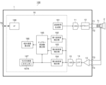
- FIG. 4 is a diagram showing the configuration of the ultrasound system according to the embodiment.
- FIG. 5 is a diagram showing an example of a transmission control signal.
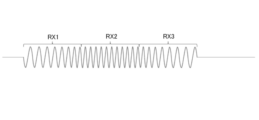
- FIG. 6 is a diagram schematically showing an example of a received wave signal.
- FIG. 7 is a diagram illustrating an example of a first reflected wave detection unit;
- FIG. 8 is a time chart showing the results of correlation processing.
- the ultrasonic system according to the embodiment described below is assumed to be mounted on a vehicle as an example, and measures the distance between the vehicle and an object to provide an alarm function, an automatic braking function, and an automatic It can be used for parking functions, etc.
- FIG. 1 shows a vehicle 200 equipped with an ultrasound system 100 (hereinafter referred to as “ultrasound system 100”) according to an embodiment, and an object (obstacle) 300 .
- Ultrasonic waves transmitted from the ultrasonic system 100 are reflected by the object 300 and received by the ultrasonic system 100 as reflected waves.
- the ultrasound system 100 also receives environmental noise N.
- FIG. 1 shows a vehicle 200 equipped with an ultrasound system 100 (hereinafter referred to as “ultrasound system 100”) according to an embodiment, and an object (obstacle) 300 .
- ultrasonic waves transmitted from the ultrasonic system 100 are reflected by the object 300 and received by the ultrasonic system 100 as reflected waves.
- the ultrasound system 100 also receives environmental noise N.
- reference data Dref is prepared in advance.
- the reference data Dref is waveform data of a reflected wave expected to be received, and is waveform data having the same frequency as the frequency of the sound wave to be transmitted.
- the frequency of the received reflected wave Rs1 shown in FIG. 2 is the same as the transmission frequency. Therefore, in the correlation result C1 obtained by the correlation processing of multiplying the reference data Dref and the reflected wave Rs1, the correlation value is always a positive value as shown in FIG. As a result, the convolution integral value obtained by temporally integrating the correlation result C1 becomes large, and the reflected wave is emphasized.
- the frequency of the received environmental noise N shown in FIG. 3 is shifted from the transmission frequency. That is, the frequency of the environmental noise N deviates from the frequency of the reference data Dref. Therefore, as shown in FIG. 3, in the correlation result C2, there is a period in which the correlation value is negative, and the convolution integral value is smaller than in FIG. In this way, it is possible to distinguish between transmitted and reflected waves and environmental noise.
- FIG. 4 is a diagram showing the configuration of the ultrasound system 100. As shown in FIG.
- the ultrasound system 100 includes a signal processing device 1 , a transformer Tr, and an ultrasound transmission/reception device 2 .
- the ultrasonic transmission/reception device 2 is externally connected to the signal processing device 1 via a transformer Tr.
- the transformer Tr may not necessarily be provided.
- the signal processing device 1 is a semiconductor integrated circuit device.
- the signal processing device 1 includes a DAC (Digital to Analog Converter) 11, a driver 12, an LNA (Low Noise Amplifier) 13, an LPF (Low Pass Filter) 14, an ADC (Analog to Digital Converter) 15, and digital processing It includes a portion 16 and external terminals T1 to T5.
- DAC Digital to Analog Converter
- driver 12 an LNA (Low Noise Amplifier) 13
- LPF Low Pass Filter
- ADC Analog to Digital Converter
- the DAC 11 D/A converts the transmission signal output from the transmission signal generation unit 161 included in the digital processing unit 16 from a digital signal to an analog signal, and outputs the signal after D/A conversion to the driver 12 .
- the output ends of the differential pair of the driver 12 are connected to the primary side of the transformer Tr via external terminals T1 and T2.
- An ultrasonic transmission/reception device 2 is connected to the secondary side of the transformer Tr.
- a driver 12 drives the ultrasonic transmission/reception device 2 based on the output signal of the DAC 11 .
- the ultrasonic transmission/reception device 2 has a piezoelectric element (not shown) and transmits and receives ultrasonic waves. That is, the ultrasonic transmission/reception device 2 functions both as a sound source and as a reception section.
- the input ends of the differential pair of LNA 13 are connected to the secondary side of transformer Tr via external terminals T3 and T4.
- the output signal of LNA 13 is supplied to ADC 15 via LPF 14 .
- the ADC 15 A/D converts the output signal of the LNA 13 from an analog signal to a digital signal, and converts the A/D converted signal to a first reflected wave detection unit 162 and a second reflected wave detection unit 163 included in the digital processing unit 16. , and the third reflected wave detection unit 164 .
- the LNA 13, LPF 14, and ADC 15 are an example of a received wave signal output unit configured to output a received wave signal based on received ultrasonic waves.
- the digital processing unit 16 includes a transmission signal generation unit 161, a first reflected wave detection unit 162, a second reflected wave detection unit 163, a third reflected wave detection unit 164, a Doppler frequency calculation unit 165, a relative velocity A calculation unit 166 , a TOF measurement unit 167 and an interface 168 are provided.
- the transmission signal generator 161 is configured to generate a transmission signal for transmitting ultrasonic waves. More specifically, the transmitted wave signal generator 161 generates a transmitted wave signal upon receiving a wave transmission command via an interface 168 from an ECU (Electronic Control Unit) (not shown) mounted on the vehicle 200 (see FIG. 1). and outputs the transmission signal to the DAC 11 .
- ECU Electronic Control Unit
- the transmission signal generator 161 converts the first chirp signal TX1, the constant frequency signal TX2, and the second chirp signal TX3 shown in FIG. It is configured to include in order the second chirp signal TX3.
- the transmission signal generator 161 is configured to generate a transmission signal based on a transmission control signal.
- the transmitted wave signal has a waveform similar to that of the transmitted wave control signal, but has a dull waveform due to the influence of circuit responsiveness and the like.
- the first chirp signal TX1 is an 8-wave chirp signal whose frequency increases from 53 kHz to 60 kHz in 1-kHz increments
- the constant-frequency signal TX2 is a 11-wave signal with a frequency of 60 kHz
- the second chirp signal TX3 is an eight-wave chirp signal whose frequency decreases from 60 kHz to 53 kHz in increments of 1 kHz. Note that the frequency and wave number of the control signal for transmission are not limited to the example shown in FIG.
- the frequency change width of the first chirp signal TX1 and the frequency change width of the second chirp signal TX3 are the same. If the frequency change width of the first chirp signal TX1 and the frequency change width of the second chirp signal TX3 are the same, the frequency change width of the entire transmission signal can be minimized. This simplifies circuit design and component selection.
- the first reflected wave detection unit 162 detects the first chirp signal of the received wave signal based on the correlation between the received wave signal output from the ADC 15 and the first reference data configured by the first chirp signal TX1. Detect part RX1 (see FIG. 6).
- the second reflected wave detector 163 detects the second chirp signal of the received wave signal based on the correlation between the received wave signal output from the ADC 15 and the second reference data composed of the second chirp signal TX3. Detect part RX3 (see FIG. 6).
- the third reflected wave detector 164 Based on the correlation between the received wave signal output from the ADC 15 and the third reference data composed of the first chirp signal TX1, the frequency signal TX2, and the second chirp signal TX3, the third reflected wave detector 164 , to detect the portion RX3 (see FIG. 6) corresponding to the second chirp signal of the received signal.
- FIG. 7 is a diagram showing an example of the first reflected wave detection section 162.
- the first reflected wave detection unit 162 in the example shown in FIG. 7 includes a reference data storage unit 162A, a correlation processing unit 162B, a correlation value summation unit 162C, and a threshold determination unit 162D.
- the reference data storage unit 162A is configured to store first reference data.
- a register can be used for the reference data storage unit 162A.
- the correlation processing unit 162B performs correlation processing based on the received wave signal output from the ADC 15 and the first reference data stored in the reference data storage unit 162A at a predetermined cycle.
- the correlation value summation unit 162C outputs a correlation convolution integral value by calculating the sum of the correlation processing results by the correlation processing unit 162B.
- the correlation convolution integral value to be output may be a value obtained by truncating a negative value such that the negative value of the calculated result is 0.
- the threshold determination unit 162D compares the correlation convolution integral value with a predetermined threshold. As shown in FIG. 8, when the correlation convolution integral value becomes greater than a predetermined threshold value and reaches a maximum value, the threshold determination unit 162D determines the portion RX1 (see FIG. 6) of the received signal corresponding to the first chirp signal. ).
- An example of the second reflected wave detection unit 163 and an example of the third reflected wave detection unit 164 are the same as an example of the first reflected wave detection unit 162 .
- the second reflected wave detector 163 uses the second reference data instead of the first reference data
- the third reflected wave detector 164 uses the third reference data instead of the first reference data.
- instead of the portion RX1 (see FIG. 6) corresponding to the first chirp signal of the received signal instead of the portion RX1 (see FIG. 6) corresponding to the first chirp signal of the received signal, A portion RX3 (see FIG. 6) corresponding to the chirp signal is detected.
- the Doppler frequency calculator 165 calculates the frequency from the first timing when the portion RX1 corresponding to the first chirp signal of the received wave signal is detected to the second timing when the portion RX3 corresponding to the second chirp signal of the received wave signal is detected. Time TM1 (FIG. 8) is measured.
- the Doppler frequency calculator 165 may incorporate a counter to measure the time TM1 using the counter, or may measure the time TM1 using the counter 167A in the TOF measuring unit 167. .
- the Doppler frequency calculation unit 165 It is desirable not to measure the time TM1, assuming that the portion RX3 corresponding to the second chirp signal of is not detected. This can suppress erroneous measurement of the time TM1.
- the detection timing of the portion RX3 corresponding to the second chirp signal of the received wave signal by the second reflected wave detection unit 163 and the detection timing of the portion RX3 of the received wave signal corresponding to the second chirp signal by the third reflected wave detection unit 164 It is desirable not to measure the time TM1 even when the detection timing is shifted by a predetermined time or more. This can suppress erroneous measurement of the time TM1.
- the Doppler frequency calculator 165 may use either of the two for the measurement of the time TM1, or use the average of both for the measurement of the time TM1.
- the Doppler frequency calculator 165 calculates the Doppler frequency of the received wave signal from the difference between the time TREF and the time TM1.
- the relative velocity calculator 166 calculates the relative velocity between the vehicle 200 (see FIG. 1) and the object 300 (see FIG. 1) from the Doppler frequency of the received wave signal calculated by the Doppler frequency calculator 165.
- the above-described first reflected wave detection unit 162, second reflected wave detection unit 163, third reflected wave detection unit 164, Doppler frequency calculation unit 165, and relative velocity calculation unit 166 detect the first chirp signal of the received wave signal. Based on the first timing for detecting the corresponding portion RX1 (see FIGS. 6 and 8) and the second timing for detecting the portion RX3 (see FIGS. 6 and 8) corresponding to the second chirp signal of the received signal , is an example of a derivation unit configured to derive a velocity relative to an object 300 (see FIG. 1).
- the TOF measurement unit 167 uses a counter 167A to measure the time (TOF) from when the ultrasonic wave is transmitted until when the reflected wave from the object 300 is received.
- the TOF measurement unit 167 stops the counting operation of the counter 167A based on the detection result of the third reflected wave detection unit 164, but instead of the detection result of the third reflected wave detection unit 164, The detection result of the wave detection unit 163 may be used, or the detection result of the third reflected wave detection unit 164 and the detection result of the second reflected wave detection unit 163 may be used.
- the interface 168 conforms to LIN (Local Interconnect Network) as an example, and communicates with an ECU (not shown) mounted on the vehicle 200 (see FIG. 1) via an external terminal T5. For example, the interface 168 sends the calculation result of the relative speed calculation unit 166 and the measurement result of the TOF measurement unit 167 to an ECU (not shown) mounted on the vehicle 200 (see FIG. 1).
- LIN Local Interconnect Network
- the transmission signal does not have to include the constant frequency signal TX2.
- the detection accuracy of the third reflected wave detector 164 is improved by including the signal TX2 of the constant frequency in the transmission signal, it is desirable that the transmission signal include the signal TX2 of the constant frequency.
- reference data composed of a constant frequency signal TX2 and a second chirp signal TX3 may be used.
- the order of the first chirp signal TX1 and the second chirp signal TX3 may be changed.
- the ultrasonic system 100 that transmits ultrasonic waves (sound waves with a high frequency exceeding audible sound) has been described, but the present invention is also applicable to a sound wave system that transmits sound waves other than ultrasonic waves. can do.
- the signal processing device (1) described above generates a transmission signal for transmitting sound waves, and includes a first chirp signal and a second chirp signal in the transmission signal.
- a received wave signal output unit 13, 14, 15
- a derivation unit 162, 163, 164, 165, 166
- one of the first chirp signal and the second chirp signal is a signal whose frequency increases with time;
- the other of the two chirp signals is a configuration (first configuration) that is a signal whose frequency decreases over time.
- the signal processing device having the first configuration above can measure the relative velocity with respect to the object.
- the derivation unit is configured to perform a second chirp signal at which the second chirp signal of the transmission signal ends from a first end timing at which the first chirp signal of the transmission signal ends.
- the configuration may be configured to derive the relative speed based on a comparison result between the time until the end timing and the time from the first timing to the second timing.
- the signal processing device having the second configuration above can calculate the relative velocity with respect to the object from the Doppler frequency of the received wave signal.
- the transmission signal generating section adds the first chirp signal, a constant frequency signal, and the second chirp signal to the transmission signal as the first chirp signal.
- a configuration (a third configuration) configured to include the signal, the constant frequency signal, and the second chirp signal in this order.
- the signal processing device having the third configuration above can improve the accuracy of the relative velocity with respect to the object.
- the derivation unit converts the second chirp signal of the received signal to the second chirp signal based on the correlation between the received signal and each of a plurality of reference data.
- a configuration (fourth configuration) configured to detect the corresponding portion may be employed.
- the signal processing device having the fourth configuration above can suppress erroneous measurement of the relative velocity with respect to the object.
- the frequency variation width of the first chirp signal and the frequency variation width of the second chirp signal are the same (fifth configuration).
- the signal processing device having the fifth configuration can minimize the frequency variation width of the entire transmission signal. This simplifies circuit design and component selection.
- the sound wave system (100) described above includes a signal processing device having any one of the first to fifth configurations, and a sound wave transmitting/receiving device (2) configured to be directly or indirectly connected to the signal processing device. ) and a configuration (sixth configuration).
- the sound wave system which is the sixth configuration above, can measure the relative velocity with the object.
- the vehicle (200) described above has a configuration (seventh configuration) including the sound wave system of the sixth configuration.
- the relative velocity to the object measured by the sound wave system can be used.
Landscapes
- Engineering & Computer Science (AREA)
- Radar, Positioning & Navigation (AREA)
- Remote Sensing (AREA)
- Physics & Mathematics (AREA)
- Computer Networks & Wireless Communication (AREA)
- General Physics & Mathematics (AREA)
- Acoustics & Sound (AREA)
- Measurement Of Velocity Or Position Using Acoustic Or Ultrasonic Waves (AREA)
Priority Applications (3)
| Application Number | Priority Date | Filing Date | Title |
|---|---|---|---|
| CN202280057643.2A CN117836664A (zh) | 2021-08-25 | 2022-06-24 | 信号处理装置、声波系统和车辆 |
| JP2023543720A JP7835767B2 (ja) | 2021-08-25 | 2022-06-24 | 信号処理装置、音波システム、及び車両 |
| US18/585,459 US20240192362A1 (en) | 2021-08-25 | 2024-02-23 | Signal processing device, sound wave system, and vehicle |
Applications Claiming Priority (2)
| Application Number | Priority Date | Filing Date | Title |
|---|---|---|---|
| JP2021136761 | 2021-08-25 | ||
| JP2021-136761 | 2021-08-25 |
Related Child Applications (1)
| Application Number | Title | Priority Date | Filing Date |
|---|---|---|---|
| US18/585,459 Continuation US20240192362A1 (en) | 2021-08-25 | 2024-02-23 | Signal processing device, sound wave system, and vehicle |
Publications (1)
| Publication Number | Publication Date |
|---|---|
| WO2023026666A1 true WO2023026666A1 (ja) | 2023-03-02 |
Family
ID=85322727
Family Applications (1)
| Application Number | Title | Priority Date | Filing Date |
|---|---|---|---|
| PCT/JP2022/025241 Ceased WO2023026666A1 (ja) | 2021-08-25 | 2022-06-24 | 信号処理装置、音波システム、及び車両 |
Country Status (4)
| Country | Link |
|---|---|
| US (1) | US20240192362A1 (https=) |
| JP (1) | JP7835767B2 (https=) |
| CN (1) | CN117836664A (https=) |
| WO (1) | WO2023026666A1 (https=) |
Citations (4)
| Publication number | Priority date | Publication date | Assignee | Title |
|---|---|---|---|---|
| WO2020004609A1 (ja) * | 2018-06-28 | 2020-01-02 | ローム株式会社 | 音波処理装置、および超音波システム |
| US20200209388A1 (en) * | 2018-12-26 | 2020-07-02 | Texas Instruments Incorporated | Ultrasonic echo processing in presence of doppler shift |
| JP2021004797A (ja) * | 2019-06-26 | 2021-01-14 | 株式会社Soken | 物体検知装置および物体検知方法 |
| WO2021130818A1 (ja) * | 2019-12-23 | 2021-07-01 | 三菱電機株式会社 | 検出装置、検出方法、及び、検出プログラム |
Family Cites Families (11)
| Publication number | Priority date | Publication date | Assignee | Title |
|---|---|---|---|---|
| JP2015172503A (ja) * | 2014-03-11 | 2015-10-01 | パナソニックIpマネジメント株式会社 | 物体検知装置 |
| KR102488038B1 (ko) * | 2015-11-19 | 2023-01-13 | 주식회사 에이치엘클레무브 | 차량용 레이더 장치 및 그의 타겟 결정 방법 |
| KR101760907B1 (ko) * | 2015-11-20 | 2017-07-24 | 주식회사 만도 | 차량용 레이더 장치 및 그의 타겟 측정 방법 |
| CN112204421B (zh) * | 2018-06-07 | 2023-06-16 | 三菱电机株式会社 | 雷达装置、控制电路以及程序存储介质 |
| CN112219128B (zh) * | 2018-06-07 | 2024-08-06 | 三菱电机株式会社 | 雷达装置、雷达装置的故障检测方法和雷达装置的运用方法 |
| JP7167495B2 (ja) * | 2018-06-12 | 2022-11-09 | 株式会社アイシン | 物体検知装置および物体検知システム |
| JP7652527B2 (ja) * | 2018-11-16 | 2025-03-27 | 株式会社アイシン | 距離検出装置および物体検出装置 |
| CN113631945A (zh) * | 2019-03-20 | 2021-11-09 | 京瓷株式会社 | 电子设备、电子设备的控制方法以及电子设备的控制程序 |
| WO2021210489A1 (ja) * | 2020-04-17 | 2021-10-21 | 株式会社村田製作所 | レーダ装置、車両、及び到来波数推定方法 |
| WO2021210465A1 (ja) * | 2020-04-17 | 2021-10-21 | 株式会社村田製作所 | レーダ装置、車両、距離測定方法 |
| JP7700544B2 (ja) * | 2021-07-07 | 2025-07-01 | 株式会社アイシン | 物体検出システムおよび物体検出装置 |
-
2022
- 2022-06-24 JP JP2023543720A patent/JP7835767B2/ja active Active
- 2022-06-24 CN CN202280057643.2A patent/CN117836664A/zh active Pending
- 2022-06-24 WO PCT/JP2022/025241 patent/WO2023026666A1/ja not_active Ceased
-
2024
- 2024-02-23 US US18/585,459 patent/US20240192362A1/en active Pending
Patent Citations (4)
| Publication number | Priority date | Publication date | Assignee | Title |
|---|---|---|---|---|
| WO2020004609A1 (ja) * | 2018-06-28 | 2020-01-02 | ローム株式会社 | 音波処理装置、および超音波システム |
| US20200209388A1 (en) * | 2018-12-26 | 2020-07-02 | Texas Instruments Incorporated | Ultrasonic echo processing in presence of doppler shift |
| JP2021004797A (ja) * | 2019-06-26 | 2021-01-14 | 株式会社Soken | 物体検知装置および物体検知方法 |
| WO2021130818A1 (ja) * | 2019-12-23 | 2021-07-01 | 三菱電機株式会社 | 検出装置、検出方法、及び、検出プログラム |
Also Published As
| Publication number | Publication date |
|---|---|
| US20240192362A1 (en) | 2024-06-13 |
| JP7835767B2 (ja) | 2026-03-25 |
| CN117836664A (zh) | 2024-04-05 |
| JPWO2023026666A1 (https=) | 2023-03-02 |
Similar Documents
| Publication | Publication Date | Title |
|---|---|---|
| CN209894972U (zh) | 声学距离测量电路 | |
| CN111413699B (zh) | 用于低频调制(lfm)啁啾信号的声学距离测量电路和方法 | |
| US11644555B2 (en) | Threshold generation for coded ultrasonic sensing | |
| CN105474039B (zh) | 用于运行车辆的周围环境检测系统的方法 | |
| CN107167808B (zh) | 用于声学距离飞行时间补偿的电路 | |
| CN112912761B (zh) | 存在多普勒频移时的超声回波处理 | |
| CN107656280B (zh) | 使用运动补偿距离的障碍物监测 | |
| CN107064939B (zh) | 用于声距测量的电路 | |
| JP2021524910A (ja) | コード化された超音波送信に対する飛行時間及びコードシグネチャ検出 | |
| US11175402B2 (en) | Time-varying template for improved short-distance performance in coded ultrasonic ranging | |
| US11982740B2 (en) | Motion-compensated distance sensing with concurrent up-chirp down-chirp waveforms | |
| US6804168B2 (en) | Method for measuring distance | |
| JP7835767B2 (ja) | 信号処理装置、音波システム、及び車両 | |
| JP7835768B2 (ja) | 信号処理装置、音波システム、及び車両 | |
| JP5784789B1 (ja) | 車両用障害物検出装置 | |
| JP2023031336A (ja) | 信号処理装置、音波システム、及び車両 | |
| JP5469995B2 (ja) | ドップラ計測器、ドップラ計測方法、潮流計、および潮流計測方法 | |
| JP2020060410A (ja) | 音波処理装置、および超音波システム | |
| WO2024180890A1 (ja) | 信号処理装置、音波システム、及び車両 | |
| WO2022260031A1 (ja) | 音波処理装置、および超音波システム | |
| JPWO2023026666A5 (https=) | ||
| US11899106B1 (en) | Dual-channel acoustic distance measurement circuit and method | |
| JP7533207B2 (ja) | 浮体検知装置 | |
| JP2024119191A (ja) | 信号処理装置、音波システム、及び車両 |
Legal Events
| Date | Code | Title | Description |
|---|---|---|---|
| 121 | Ep: the epo has been informed by wipo that ep was designated in this application |
Ref document number: 22860960 Country of ref document: EP Kind code of ref document: A1 |
|
| WWE | Wipo information: entry into national phase |
Ref document number: 2023543720 Country of ref document: JP |
|
| WWE | Wipo information: entry into national phase |
Ref document number: 202280057643.2 Country of ref document: CN |
|
| NENP | Non-entry into the national phase |
Ref country code: DE |
|
| 122 | Ep: pct application non-entry in european phase |
Ref document number: 22860960 Country of ref document: EP Kind code of ref document: A1 |