WO2023026666A1 - 信号処理装置、音波システム、及び車両 - Google Patents
信号処理装置、音波システム、及び車両 Download PDFInfo
- Publication number
- WO2023026666A1 WO2023026666A1 PCT/JP2022/025241 JP2022025241W WO2023026666A1 WO 2023026666 A1 WO2023026666 A1 WO 2023026666A1 JP 2022025241 W JP2022025241 W JP 2022025241W WO 2023026666 A1 WO2023026666 A1 WO 2023026666A1
- Authority
- WO
- WIPO (PCT)
- Prior art keywords
- signal
- chirp
- chirp signal
- transmission
- processing device
- Prior art date
Links
- 230000005540 biological transmission Effects 0.000 claims abstract description 47
- 238000009795 derivation Methods 0.000 claims abstract description 9
- 230000007423 decrease Effects 0.000 claims abstract description 5
- 230000007274 generation of a signal involved in cell-cell signaling Effects 0.000 claims abstract description 5
- 238000001514 detection method Methods 0.000 description 43
- 238000005259 measurement Methods 0.000 description 11
- 238000004364 calculation method Methods 0.000 description 9
- 238000010586 diagram Methods 0.000 description 9
- 238000002604 ultrasonography Methods 0.000 description 9
- 238000013500 data storage Methods 0.000 description 5
- 230000007613 environmental effect Effects 0.000 description 4
- 238000006243 chemical reaction Methods 0.000 description 1
- 238000012986 modification Methods 0.000 description 1
- 230000004048 modification Effects 0.000 description 1
- 230000004043 responsiveness Effects 0.000 description 1
- 239000004065 semiconductor Substances 0.000 description 1
Images


Classifications
-
- G—PHYSICS
- G01—MEASURING; TESTING
- G01S—RADIO DIRECTION-FINDING; RADIO NAVIGATION; DETERMINING DISTANCE OR VELOCITY BY USE OF RADIO WAVES; LOCATING OR PRESENCE-DETECTING BY USE OF THE REFLECTION OR RERADIATION OF RADIO WAVES; ANALOGOUS ARRANGEMENTS USING OTHER WAVES
- G01S15/00—Systems using the reflection or reradiation of acoustic waves, e.g. sonar systems
- G01S15/02—Systems using the reflection or reradiation of acoustic waves, e.g. sonar systems using reflection of acoustic waves
- G01S15/06—Systems determining the position data of a target
- G01S15/08—Systems for measuring distance only
- G01S15/32—Systems for measuring distance only using transmission of continuous waves, whether amplitude-, frequency-, or phase-modulated, or unmodulated
-
- G—PHYSICS
- G01—MEASURING; TESTING
- G01S—RADIO DIRECTION-FINDING; RADIO NAVIGATION; DETERMINING DISTANCE OR VELOCITY BY USE OF RADIO WAVES; LOCATING OR PRESENCE-DETECTING BY USE OF THE REFLECTION OR RERADIATION OF RADIO WAVES; ANALOGOUS ARRANGEMENTS USING OTHER WAVES
- G01S15/00—Systems using the reflection or reradiation of acoustic waves, e.g. sonar systems
- G01S15/02—Systems using the reflection or reradiation of acoustic waves, e.g. sonar systems using reflection of acoustic waves
- G01S15/50—Systems of measurement, based on relative movement of the target
- G01S15/58—Velocity or trajectory determination systems; Sense-of-movement determination systems
-
- G—PHYSICS
- G01—MEASURING; TESTING
- G01S—RADIO DIRECTION-FINDING; RADIO NAVIGATION; DETERMINING DISTANCE OR VELOCITY BY USE OF RADIO WAVES; LOCATING OR PRESENCE-DETECTING BY USE OF THE REFLECTION OR RERADIATION OF RADIO WAVES; ANALOGOUS ARRANGEMENTS USING OTHER WAVES
- G01S7/00—Details of systems according to groups G01S13/00, G01S15/00, G01S17/00
- G01S7/52—Details of systems according to groups G01S13/00, G01S15/00, G01S17/00 of systems according to group G01S15/00
- G01S7/523—Details of pulse systems
- G01S7/524—Transmitters
-
- G—PHYSICS
- G01—MEASURING; TESTING
- G01S—RADIO DIRECTION-FINDING; RADIO NAVIGATION; DETERMINING DISTANCE OR VELOCITY BY USE OF RADIO WAVES; LOCATING OR PRESENCE-DETECTING BY USE OF THE REFLECTION OR RERADIATION OF RADIO WAVES; ANALOGOUS ARRANGEMENTS USING OTHER WAVES
- G01S7/00—Details of systems according to groups G01S13/00, G01S15/00, G01S17/00
- G01S7/52—Details of systems according to groups G01S13/00, G01S15/00, G01S17/00 of systems according to group G01S15/00
- G01S7/523—Details of pulse systems
- G01S7/526—Receivers
Definitions
- the invention disclosed in this specification provides a signal processing device for processing a transmission signal for transmitting sound waves and a reception signal based on reception of sound waves, a sound wave system including the signal processing device, and It relates to a vehicle equipped with the sound wave system.
- a conventional ultrasonic system can measure the distance from the ultrasonic system to an object, but cannot measure the relative velocity between the ultrasonic system and the object.
- a signal processing apparatus disclosed herein generates a transmit signal for transmitting an acoustic wave, and is configured to include a first chirp signal and a second chirp signal in the transmit signal.
- a wave signal generator, a received wave signal output unit configured to output a received wave signal based on received sound waves, and a first timing for detecting a portion of the received wave signal corresponding to the first chirp signal.
- a derivation unit configured to derive a relative velocity with respect to an object based on the first One of the chirp signal and the second chirp signal is a signal whose frequency increases over time, and the other of the first chirp signal and the second chirp signal is a signal whose frequency decreases over time.
- the acoustic wave system disclosed in the present specification includes the signal processing device configured as described above and an acoustic wave transmitting/receiving device configured to be directly or indirectly connected to the signal processing device. .
- the vehicle disclosed in this specification is configured to include the acoustic wave system configured as described above.
- FIG. 1 is a diagram schematically showing a vehicle equipped with an ultrasonic system according to an embodiment and an object.
- FIG. 2 is a diagram for explaining an example of correlation processing.
- FIG. 3 is a diagram for explaining an example of correlation processing.
- FIG. 4 is a diagram showing the configuration of the ultrasound system according to the embodiment.
- FIG. 5 is a diagram showing an example of a transmission control signal.
- FIG. 6 is a diagram schematically showing an example of a received wave signal.
- FIG. 7 is a diagram illustrating an example of a first reflected wave detection unit;
- FIG. 8 is a time chart showing the results of correlation processing.
- the ultrasonic system according to the embodiment described below is assumed to be mounted on a vehicle as an example, and measures the distance between the vehicle and an object to provide an alarm function, an automatic braking function, and an automatic It can be used for parking functions, etc.
- FIG. 1 shows a vehicle 200 equipped with an ultrasound system 100 (hereinafter referred to as “ultrasound system 100”) according to an embodiment, and an object (obstacle) 300 .
- Ultrasonic waves transmitted from the ultrasonic system 100 are reflected by the object 300 and received by the ultrasonic system 100 as reflected waves.
- the ultrasound system 100 also receives environmental noise N.
- FIG. 1 shows a vehicle 200 equipped with an ultrasound system 100 (hereinafter referred to as “ultrasound system 100”) according to an embodiment, and an object (obstacle) 300 .
- ultrasonic waves transmitted from the ultrasonic system 100 are reflected by the object 300 and received by the ultrasonic system 100 as reflected waves.
- the ultrasound system 100 also receives environmental noise N.
- reference data Dref is prepared in advance.
- the reference data Dref is waveform data of a reflected wave expected to be received, and is waveform data having the same frequency as the frequency of the sound wave to be transmitted.
- the frequency of the received reflected wave Rs1 shown in FIG. 2 is the same as the transmission frequency. Therefore, in the correlation result C1 obtained by the correlation processing of multiplying the reference data Dref and the reflected wave Rs1, the correlation value is always a positive value as shown in FIG. As a result, the convolution integral value obtained by temporally integrating the correlation result C1 becomes large, and the reflected wave is emphasized.
- the frequency of the received environmental noise N shown in FIG. 3 is shifted from the transmission frequency. That is, the frequency of the environmental noise N deviates from the frequency of the reference data Dref. Therefore, as shown in FIG. 3, in the correlation result C2, there is a period in which the correlation value is negative, and the convolution integral value is smaller than in FIG. In this way, it is possible to distinguish between transmitted and reflected waves and environmental noise.
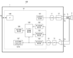
- FIG. 4 is a diagram showing the configuration of the ultrasound system 100. As shown in FIG.
- the ultrasound system 100 includes a signal processing device 1 , a transformer Tr, and an ultrasound transmission/reception device 2 .
- the ultrasonic transmission/reception device 2 is externally connected to the signal processing device 1 via a transformer Tr.
- the transformer Tr may not necessarily be provided.
- the signal processing device 1 is a semiconductor integrated circuit device.
- the signal processing device 1 includes a DAC (Digital to Analog Converter) 11, a driver 12, an LNA (Low Noise Amplifier) 13, an LPF (Low Pass Filter) 14, an ADC (Analog to Digital Converter) 15, and digital processing It includes a portion 16 and external terminals T1 to T5.
- DAC Digital to Analog Converter
- driver 12 an LNA (Low Noise Amplifier) 13
- LPF Low Pass Filter
- ADC Analog to Digital Converter
- the DAC 11 D/A converts the transmission signal output from the transmission signal generation unit 161 included in the digital processing unit 16 from a digital signal to an analog signal, and outputs the signal after D/A conversion to the driver 12 .
- the output ends of the differential pair of the driver 12 are connected to the primary side of the transformer Tr via external terminals T1 and T2.
- An ultrasonic transmission/reception device 2 is connected to the secondary side of the transformer Tr.
- a driver 12 drives the ultrasonic transmission/reception device 2 based on the output signal of the DAC 11 .
- the ultrasonic transmission/reception device 2 has a piezoelectric element (not shown) and transmits and receives ultrasonic waves. That is, the ultrasonic transmission/reception device 2 functions both as a sound source and as a reception section.
- the input ends of the differential pair of LNA 13 are connected to the secondary side of transformer Tr via external terminals T3 and T4.
- the output signal of LNA 13 is supplied to ADC 15 via LPF 14 .
- the ADC 15 A/D converts the output signal of the LNA 13 from an analog signal to a digital signal, and converts the A/D converted signal to a first reflected wave detection unit 162 and a second reflected wave detection unit 163 included in the digital processing unit 16. , and the third reflected wave detection unit 164 .
- the LNA 13, LPF 14, and ADC 15 are an example of a received wave signal output unit configured to output a received wave signal based on received ultrasonic waves.
- the digital processing unit 16 includes a transmission signal generation unit 161, a first reflected wave detection unit 162, a second reflected wave detection unit 163, a third reflected wave detection unit 164, a Doppler frequency calculation unit 165, a relative velocity A calculation unit 166 , a TOF measurement unit 167 and an interface 168 are provided.
- the transmission signal generator 161 is configured to generate a transmission signal for transmitting ultrasonic waves. More specifically, the transmitted wave signal generator 161 generates a transmitted wave signal upon receiving a wave transmission command via an interface 168 from an ECU (Electronic Control Unit) (not shown) mounted on the vehicle 200 (see FIG. 1). and outputs the transmission signal to the DAC 11 .
- ECU Electronic Control Unit
- the transmission signal generator 161 converts the first chirp signal TX1, the constant frequency signal TX2, and the second chirp signal TX3 shown in FIG. It is configured to include in order the second chirp signal TX3.
- the transmission signal generator 161 is configured to generate a transmission signal based on a transmission control signal.
- the transmitted wave signal has a waveform similar to that of the transmitted wave control signal, but has a dull waveform due to the influence of circuit responsiveness and the like.
- the first chirp signal TX1 is an 8-wave chirp signal whose frequency increases from 53 kHz to 60 kHz in 1-kHz increments
- the constant-frequency signal TX2 is a 11-wave signal with a frequency of 60 kHz
- the second chirp signal TX3 is an eight-wave chirp signal whose frequency decreases from 60 kHz to 53 kHz in increments of 1 kHz. Note that the frequency and wave number of the control signal for transmission are not limited to the example shown in FIG.
- the frequency change width of the first chirp signal TX1 and the frequency change width of the second chirp signal TX3 are the same. If the frequency change width of the first chirp signal TX1 and the frequency change width of the second chirp signal TX3 are the same, the frequency change width of the entire transmission signal can be minimized. This simplifies circuit design and component selection.
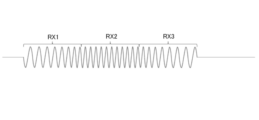
- the first reflected wave detection unit 162 detects the first chirp signal of the received wave signal based on the correlation between the received wave signal output from the ADC 15 and the first reference data configured by the first chirp signal TX1. Detect part RX1 (see FIG. 6).
- the second reflected wave detector 163 detects the second chirp signal of the received wave signal based on the correlation between the received wave signal output from the ADC 15 and the second reference data composed of the second chirp signal TX3. Detect part RX3 (see FIG. 6).
- the third reflected wave detector 164 Based on the correlation between the received wave signal output from the ADC 15 and the third reference data composed of the first chirp signal TX1, the frequency signal TX2, and the second chirp signal TX3, the third reflected wave detector 164 , to detect the portion RX3 (see FIG. 6) corresponding to the second chirp signal of the received signal.
- FIG. 7 is a diagram showing an example of the first reflected wave detection section 162.
- the first reflected wave detection unit 162 in the example shown in FIG. 7 includes a reference data storage unit 162A, a correlation processing unit 162B, a correlation value summation unit 162C, and a threshold determination unit 162D.
- the reference data storage unit 162A is configured to store first reference data.
- a register can be used for the reference data storage unit 162A.
- the correlation processing unit 162B performs correlation processing based on the received wave signal output from the ADC 15 and the first reference data stored in the reference data storage unit 162A at a predetermined cycle.
- the correlation value summation unit 162C outputs a correlation convolution integral value by calculating the sum of the correlation processing results by the correlation processing unit 162B.
- the correlation convolution integral value to be output may be a value obtained by truncating a negative value such that the negative value of the calculated result is 0.
- the threshold determination unit 162D compares the correlation convolution integral value with a predetermined threshold. As shown in FIG. 8, when the correlation convolution integral value becomes greater than a predetermined threshold value and reaches a maximum value, the threshold determination unit 162D determines the portion RX1 (see FIG. 6) of the received signal corresponding to the first chirp signal. ).
- An example of the second reflected wave detection unit 163 and an example of the third reflected wave detection unit 164 are the same as an example of the first reflected wave detection unit 162 .
- the second reflected wave detector 163 uses the second reference data instead of the first reference data
- the third reflected wave detector 164 uses the third reference data instead of the first reference data.
- instead of the portion RX1 (see FIG. 6) corresponding to the first chirp signal of the received signal instead of the portion RX1 (see FIG. 6) corresponding to the first chirp signal of the received signal, A portion RX3 (see FIG. 6) corresponding to the chirp signal is detected.
- the Doppler frequency calculator 165 calculates the frequency from the first timing when the portion RX1 corresponding to the first chirp signal of the received wave signal is detected to the second timing when the portion RX3 corresponding to the second chirp signal of the received wave signal is detected. Time TM1 (FIG. 8) is measured.
- the Doppler frequency calculator 165 may incorporate a counter to measure the time TM1 using the counter, or may measure the time TM1 using the counter 167A in the TOF measuring unit 167. .
- the Doppler frequency calculation unit 165 It is desirable not to measure the time TM1, assuming that the portion RX3 corresponding to the second chirp signal of is not detected. This can suppress erroneous measurement of the time TM1.
- the detection timing of the portion RX3 corresponding to the second chirp signal of the received wave signal by the second reflected wave detection unit 163 and the detection timing of the portion RX3 of the received wave signal corresponding to the second chirp signal by the third reflected wave detection unit 164 It is desirable not to measure the time TM1 even when the detection timing is shifted by a predetermined time or more. This can suppress erroneous measurement of the time TM1.
- the Doppler frequency calculator 165 may use either of the two for the measurement of the time TM1, or use the average of both for the measurement of the time TM1.
- the Doppler frequency calculator 165 calculates the Doppler frequency of the received wave signal from the difference between the time TREF and the time TM1.
- the relative velocity calculator 166 calculates the relative velocity between the vehicle 200 (see FIG. 1) and the object 300 (see FIG. 1) from the Doppler frequency of the received wave signal calculated by the Doppler frequency calculator 165.
- the above-described first reflected wave detection unit 162, second reflected wave detection unit 163, third reflected wave detection unit 164, Doppler frequency calculation unit 165, and relative velocity calculation unit 166 detect the first chirp signal of the received wave signal. Based on the first timing for detecting the corresponding portion RX1 (see FIGS. 6 and 8) and the second timing for detecting the portion RX3 (see FIGS. 6 and 8) corresponding to the second chirp signal of the received signal , is an example of a derivation unit configured to derive a velocity relative to an object 300 (see FIG. 1).
- the TOF measurement unit 167 uses a counter 167A to measure the time (TOF) from when the ultrasonic wave is transmitted until when the reflected wave from the object 300 is received.
- the TOF measurement unit 167 stops the counting operation of the counter 167A based on the detection result of the third reflected wave detection unit 164, but instead of the detection result of the third reflected wave detection unit 164, The detection result of the wave detection unit 163 may be used, or the detection result of the third reflected wave detection unit 164 and the detection result of the second reflected wave detection unit 163 may be used.
- the interface 168 conforms to LIN (Local Interconnect Network) as an example, and communicates with an ECU (not shown) mounted on the vehicle 200 (see FIG. 1) via an external terminal T5. For example, the interface 168 sends the calculation result of the relative speed calculation unit 166 and the measurement result of the TOF measurement unit 167 to an ECU (not shown) mounted on the vehicle 200 (see FIG. 1).
- LIN Local Interconnect Network
- the transmission signal does not have to include the constant frequency signal TX2.
- the detection accuracy of the third reflected wave detector 164 is improved by including the signal TX2 of the constant frequency in the transmission signal, it is desirable that the transmission signal include the signal TX2 of the constant frequency.
- reference data composed of a constant frequency signal TX2 and a second chirp signal TX3 may be used.
- the order of the first chirp signal TX1 and the second chirp signal TX3 may be changed.
- the ultrasonic system 100 that transmits ultrasonic waves (sound waves with a high frequency exceeding audible sound) has been described, but the present invention is also applicable to a sound wave system that transmits sound waves other than ultrasonic waves. can do.
- the signal processing device (1) described above generates a transmission signal for transmitting sound waves, and includes a first chirp signal and a second chirp signal in the transmission signal.
- a received wave signal output unit 13, 14, 15
- a derivation unit 162, 163, 164, 165, 166
- one of the first chirp signal and the second chirp signal is a signal whose frequency increases with time;
- the other of the two chirp signals is a configuration (first configuration) that is a signal whose frequency decreases over time.
- the signal processing device having the first configuration above can measure the relative velocity with respect to the object.
- the derivation unit is configured to perform a second chirp signal at which the second chirp signal of the transmission signal ends from a first end timing at which the first chirp signal of the transmission signal ends.
- the configuration may be configured to derive the relative speed based on a comparison result between the time until the end timing and the time from the first timing to the second timing.
- the signal processing device having the second configuration above can calculate the relative velocity with respect to the object from the Doppler frequency of the received wave signal.
- the transmission signal generating section adds the first chirp signal, a constant frequency signal, and the second chirp signal to the transmission signal as the first chirp signal.
- a configuration (a third configuration) configured to include the signal, the constant frequency signal, and the second chirp signal in this order.
- the signal processing device having the third configuration above can improve the accuracy of the relative velocity with respect to the object.
- the derivation unit converts the second chirp signal of the received signal to the second chirp signal based on the correlation between the received signal and each of a plurality of reference data.
- a configuration (fourth configuration) configured to detect the corresponding portion may be employed.
- the signal processing device having the fourth configuration above can suppress erroneous measurement of the relative velocity with respect to the object.
- the frequency variation width of the first chirp signal and the frequency variation width of the second chirp signal are the same (fifth configuration).
- the signal processing device having the fifth configuration can minimize the frequency variation width of the entire transmission signal. This simplifies circuit design and component selection.
- the sound wave system (100) described above includes a signal processing device having any one of the first to fifth configurations, and a sound wave transmitting/receiving device (2) configured to be directly or indirectly connected to the signal processing device. ) and a configuration (sixth configuration).
- the sound wave system which is the sixth configuration above, can measure the relative velocity with the object.
- the vehicle (200) described above has a configuration (seventh configuration) including the sound wave system of the sixth configuration.
- the relative velocity to the object measured by the sound wave system can be used.
Abstract
信号処理装置は、音波の送波のための送波信号を生成し、前記送波信号に第1,2チャープ信号(TX1,TX3)を含めるように構成される送波信号生成部と、音波の受波に基づく受波信号を出力するように構成される受波信号出力部と、前記受波信号の前記第1チャープ信号(TX1)に対応する部分(RX1)を検出する第1タイミングと、前記受波信号の前記第2チャープ信号(TX3)に対応する部分(RX3)を検出する第2タイミングとに基づき、対象物との相対速度を導出するように構成される導出部と、を備える。前記第1,2チャープ信号の一方は時間の経過とともに周波数が増加する信号であり、他方は時間の経過とともに周波数が減少する信号である。
Description
本明細書中に開示されている発明は、音波の送波のための送波信号と音波の受波に基づく受波信号とを処理する信号処理装置、当該信号処理装置を備える音波システム、及び当該音波システムを備える車両に関する。
従来、超音波を発生させて障害物からの反射波が返ってくるまでの時間TOF(Time Of Flight)を計測することにより対象物(障害物)までの距離を測定する超音波システムが知られている(例えば特許文献1参照)。このような超音波システムは車両に搭載されることが多く、一例として車載用クリアランスソナーが知られている。
従来の超音波システムは、当該超音波システムから対象物までの距離を測定できるが、当該超音波システムと対象物との相対速度を測定することができない。
本明細書中に開示されている信号処理装置は、音波の送波のための送波信号を生成し、前記送波信号に第1チャープ信号及び第2チャープ信号を含めるように構成される送波信号生成部と、音波の受波に基づく受波信号を出力するように構成される受波信号出力部と、前記受波信号の前記第1チャープ信号に対応する部分を検出する第1タイミングと、前記受波信号の前記第2チャープ信号に対応する部分を検出する第2タイミングとに基づき、対象物との相対速度を導出するように構成される導出部と、を備え、前記第1チャープ信号及び前記第2チャープ信号の一方は、時間の経過とともに周波数が増加する信号であり、前記第1チャープ信号及び前記第2チャープ信号の他方は、時間の経過とともに周波数が減少する信号である構成である。
本明細書中に開示されている音波システムは、上記構成の信号処理装置と、前記信号処理装置に直接的又は間接的に接続されるように構成される音波送受信装置と、を備える構成である。
本明細書中に開示されている車両は、上記構成の音波システムを備える構成である。
本明細書中に開示されている信号処理装置、音波システム、及び車両によれば、対象物との相対速度を測定することができる。
以下に本発明の一実施形態について図面を参照して説明する。なお、以下に説明する実施形態に係る超音波システムは、一例として車両に搭載することを想定しており、車両と対象物との間の距離を測定することによる警報機能、自動ブレーキ機能および自動駐車機能等に利用できる。
<相関処理>
まず、実施形態に係る超音波システムで用いる相関処理の概要について説明する。図1には、実施形態に係る超音波システム100(以下、「超音波システム100」という)を搭載した車両200と、対象物(障害物)300とが示されている。超音波システム100から送波された超音波は、対象物300で反射して反射波として超音波システム100により受波される。このとき、超音波システム100は、環境ノイズNの受波も行う。
まず、実施形態に係る超音波システムで用いる相関処理の概要について説明する。図1には、実施形態に係る超音波システム100(以下、「超音波システム100」という)を搭載した車両200と、対象物(障害物)300とが示されている。超音波システム100から送波された超音波は、対象物300で反射して反射波として超音波システム100により受波される。このとき、超音波システム100は、環境ノイズNの受波も行う。
ここで、相関処理について、図2及び図3を用いて説明する。図2では、参照データDrefが予め用意される。参照データDrefは、受波が予想される反射波の波形データであり、送波する音波の周波数と同じ周波数の波形データである。図2に示す受波した反射波Rs1の周波数は、送波周波数と同じとなる。従って、参照データDrefと反射波Rs1とを乗算する相関処理によって得られる相関結果C1では、図2に示すように常に相関値が正の値となる。これにより、相関結果C1を時間的に積分して得られる畳み込み積分値は大きくなり、反射波が強調される。
一方、図3に示す受波した環境ノイズNの周波数は、送波周波数からずれている。すなわち、環境ノイズNの周波数は、参照データDrefの周波数よりずれてしまう。従って、図3に示すように、相関結果C2では、相関値が負となる期間が生じることとなり、畳み込み積分値が図2に比べて小さくなる。このようにして、送波に基づく反射波と、環境ノイズとを区別することができる。
<超音波システム>
次に、超音波システム100について説明する。図4は、超音波システム100の構成を示す図である。
次に、超音波システム100について説明する。図4は、超音波システム100の構成を示す図である。
超音波システム100は、信号処理装置1と、トランスTrと、超音波送受信装置2と、を備える。超音波送受信装置2は、信号処理装置1に対してトランスTrを介して外付けに接続される。なお、トランスTrは、必ずしも設けなくてもよい。
信号処理装置1は、半導体集積回路装置である。信号処理装置1は、DAC(Digital to Analog Converter)11と、ドライバ12と、LNA(Low Noise Amplifier)13と、LPF(Low Pass Filter)14と、ADC(Analog to Digital Converter)15と、デジタル処理部16と、外部端子T1~T5と、を備える。
DAC11は、デジタル処理部16に含まれる送波信号生成部161から出力される送波信号をデジタル信号からアナログ信号へD/A変換し、D/A変換後の信号をドライバ12に出力する。
ドライバ12の差動対の出力端は、外部端子T1及びT2を介してトランスTrの1次側に接続される。トランスTrの2次側には超音波送受信装置2が接続される。ドライバ12は、DAC11の出力信号に基づき超音波送受信装置2を駆動する。
超音波送受信装置2は、不図示の圧電素子を有し、超音波の送波および受波を行う。すなわち、超音波送受信装置2は、音源としても受信部としても機能する。
LNA13の差動対の入力端は、外部端子T3及びT4を介してトランスTrの2次側に接続される。LNA13の出力信号は、LPF14を介してADC15に供給される。ADC15は、LNA13の出力信号をアナログ信号からデジタル信号へA/D変換し、A/D変換後の信号をデジタル処理部16に含まれる第1反射波検出部162、第2反射波検出部163、及び第3反射波検出部164に出力する。
LNA13、LPF14、及びADC15は、超音波の受波に基づく受波信号を出力するように構成される受波信号出力部の一例である。
デジタル処理部16は、送波信号生成部161と、第1反射波検出部162と、第2反射波検出部163と、第3反射波検出部164と、ドップラー周波数算出部165と、相対速度算出部166と、TOF計測部167と、インタフェース168と、を備える。
送波信号生成部161は、超音波の送波のための送波信号を生成するように構成される。より詳細には、送波信号生成部161は、車両200(図1参照)に搭載される不図示のECU(Electronic Control Unit)からインタフェース168を介して送波命令を受けると、送波信号を生成し、当該送波信号をDAC11に出力する。
送波信号生成部161は、送波の制御信号に図5に示す第1チャープ信号TX1、一定周波数の信号TX2、及び第2チャープ信号TX3を第1チャープ信号TX1、一定周波数の信号TX2、及び第2チャープ信号TX3の順で含めるように構成される。送波信号生成部161は、送波の制御信号に基づく送波信号を生成するように構成される。送波信号は、送波の制御信号と概略同様の波形になるが、回路の応答性等の影響によってなまりのある波形になる。
図5に示す例では、第1チャープ信号TX1は、周波数が53kHz~60kHzに1kHz刻みに増加する8波のチャープ信号であり、一定周波数の信号TX2は、周波数が60kHzの11波の信号であり、第2チャープ信号TX3は、周波数が60kHz~53kHzに1kHz刻みに減少する8波のチャープ信号である。なお、送波の制御信号の周波数及び波数は図5に示す例に限定されない。
ただし、第1チャープ信号TX1の周波数変化幅と第2チャープ信号TX3の周波数変化幅とが同一であることが望ましい。第1チャープ信号TX1の周波数変化幅と第2チャープ信号TX3の周波数変化幅とが同一であれば、送波信号全体の周波数変化幅を最小限に抑えることができる。これにより、回路設計、部品の選定が簡単になる。
第1反射波検出部162は、ADC15から出力される受波信号と、第1チャープ信号TX1によって構成される第1参照データとの相関に基づいて、受波信号の第1チャープ信号に対応する部分RX1(図6参照)を検出する。
第2反射波検出部163は、ADC15から出力される受波信号と、第2チャープ信号TX3によって構成される第2参照データとの相関に基づいて、受波信号の第2チャープ信号に対応する部分RX3(図6参照)を検出する。
第3反射波検出部164は、ADC15から出力される受波信号と、第1チャープ信号TX1、周波数の信号TX2、及び第2チャープ信号TX3によって構成される第3参照データとの相関に基づいて、受波信号の第2チャープ信号に対応する部分RX3(図6参照)を検出する。
図7は、第1反射波検出部162の一例を示す図である。図7に示す例の第1反射波検出部162は、参照データ格納部162Aと、相関処理部162Bと、相関値和算部162Cと、閾値判定部162Dと、を備える。参照データ格納部162Aは、第1参照データを格納するように構成される。参照データ格納部162Aには、例えばレジスタを用いることができる。
相関処理部162Bは、所定の周期で、ADC15から出力される受波信号と、参照データ格納部162Aに格納されている第1参照データとに基づき相関処理を行う。
相関値和算部162Cは、相関処理部162Bによる相関処理結果の総和を算出することで相関畳み込み積分値を出力する。なお、出力する相関畳み込み積分値としては、算出された結果の負値は0とする負値を切り捨てたものとしてもよい。
閾値判定部162Dは、相関畳み込み積分値と所定の閾値とを比較する。閾値判定部162Dは、図8に示すように、相関畳み込み積分値が所定の閾値より大きくなり且つ極大値になったときに、受波信号の第1チャープ信号に対応する部分RX1(図6参照)を検出する。
第2反射波検出部163の一例及び第3反射波検出部164の一例は、第1反射波検出部162の一例と同様である。ただし、第2反射波検出部163では第1参照データの代わりに第2参照データが用いられ、第3反射波検出部164では第1参照データの代わりに第3参照データが用いられる。また、第2反射波検出部163の一例及び第3反射波検出部164の一例では、受波信号の第1チャープ信号に対応する部分RX1(図6参照)の代わりに受波信号の第2チャープ信号に対応する部分RX3(図6参照)が検出される。
ドップラー周波数算出部165は、送波信号の第1チャープ信号TX1が終了する第1終了タイミングから送波信号の第2チャープ信号TX3が終了する第2終了タイミングまでの時間TREFを記憶する記憶部(不図示)を備える。ドップラー周波数算出部165は、受波信号の第1チャープ信号に対応する部分RX1が検出された第1タイミングから受波信号の第2チャープ信号に対応する部分RX3が検出された第2タイミングまでの時間TM1(図8)を測定する。ドップラー周波数算出部165は、カウンタを内蔵し、その内蔵しているカウンタを用いて時間TM1を測定してもよく、TOF計測部167内のカウンタ167Aを利用して時間TM1を測定してもよい。
なお、第2反射波検出部163及び第3反射波検出部164の一方のみによってしか受波信号の第2チャープ信号に対応する部分RX3が検出されない場合、ドップラー周波数算出部165は、受波信号の第2チャープ信号に対応する部分RX3が検出されなかったとみなし、時間TM1を測定しないことが望しい。これにより、時間TM1の誤測定を抑制することができる。また、第2反射波検出部163による受波信号の第2チャープ信号に対応する部分RX3の検出タイミングと及び第3反射波検出部164による受波信号の第2チャープ信号に対応する部分RX3の検出タイミングが所定時間以上ずれた場合も、時間TM1を測定しないことが望しい。これにより、時間TM1の誤測定を抑制することができる。
第2反射波検出部163による受波信号の第2チャープ信号に対応する部分RX3の検出タイミングと及び第3反射波検出部164による受波信号の第2チャープ信号に対応する部分RX3の検出タイミングが上記の所定時間未満ではあるが互いにずれた場合、ドップラー周波数算出部165は、両者のいずれかを時間TM1の測定のために用いてもよく、両者の平均を時間TM1の測定のために用いてもよい。
ドップラー周波数算出部165は、時間TREFと時間TM1との差から受波信号のドップラー周波数を算出する。
相対速度算出部166は、ドップラー周波数算出部165によって算出された受波信号のドップラー周波数から車両200(図1参照)と対象物300(図1参照)との相対速度を算出する。
上述した、第1反射波検出部162、第2反射波検出部163、第3反射波検出部164、ドップラー周波数算出部165、及び相対速度算出部166は、受波信号の第1チャープ信号に対応する部分RX1(図6及び図8参照)を検出する第1タイミングと、受波信号の第2チャープ信号に対応する部分RX3(図6及び図8参照)を検出する第2タイミングとに基づき、対象物300(図1参照)との相対速度を導出するように構成される導出部の一例である。
TOF計測部167は、カウンタ167Aを用いて、超音波を送波してから対象物300での反射による反射波を受波するまでの時間(TOF)を計測する。なお、本実施形態では、TOF計測部167は、第3反射波検出部164の検出結果によりカウンタ167Aのカウント動作を停止させるが、第3反射波検出部164の検出結果の代わりに第2反射波検出部163の検出結果を用いてもよく、第3反射波検出部164の検出結果及び第2反射波検出部163の検出結果を用いてもよい。
インタフェース168は、一例としてLIN(Local Interconnect Network)に準拠し、外部端子T5を介して車両200(図1参照)に搭載される不図示のECUとの間で通信を行う。例えば、インタフェース168は、相対速度算出部166の算出結果及びTOF計測部167の計測結果を、車両200(図1参照)に搭載される不図示のECUに送る。
<その他>
なお、本発明の構成は、上記実施形態のほか、発明の主旨を逸脱しない範囲で種々の変更を加えることが可能である。上記実施形態は、全ての点で例示であって、制限的なものではないと考えられるべきであり、本発明の技術的範囲は、上記実施形態の説明ではなく、特許請求の範囲によって示されるものであり、特許請求の範囲と均等の意味及び範囲内に属する全ての変更が含まれると理解されるべきである。
なお、本発明の構成は、上記実施形態のほか、発明の主旨を逸脱しない範囲で種々の変更を加えることが可能である。上記実施形態は、全ての点で例示であって、制限的なものではないと考えられるべきであり、本発明の技術的範囲は、上記実施形態の説明ではなく、特許請求の範囲によって示されるものであり、特許請求の範囲と均等の意味及び範囲内に属する全ての変更が含まれると理解されるべきである。
例えば、送波信号は一定周波数の信号TX2を含まなくてもよい。ただし、送波信号が一定周波数の信号TX2を含むことにより第3反射波検出部164での検出精度が向上するので、送波信号が一定周波数の信号TX2を含むことが望ましい。
また例えば、上述した第2参照データ又は第3参照データの代わりに、一定周波数の信号TX2及び第2チャープ信号TX3によって構成される参照データを用いてもよい。
また例えば、送波信号において、第1チャープ信号TX1と第2チャープ信号TX3との順序を入れ替えてもよい。
上記実施形態では、超音波(可聴音を超える高い振動数の音波)を送波する超音波システム100について説明したが、超音波以外の音波を送波する音波システムに対しても本発明を適用することができる。
以上説明した信号処理装置(1)は、音波の送波のための送波信号を生成し、前記送波信号に第1チャープ信号及び第2チャープ信号を含めるように構成される送波信号生成部(161)と、音波の受波に基づく受波信号を出力するように構成される受波信号出力部(13、14、15)と、前記受波信号の前記第1チャープ信号に対応する部分を検出する第1タイミングと、前記受波信号の前記第2チャープ信号に対応する部分を検出する第2タイミングとに基づき、対象物との相対速度を導出するように構成される導出部(162、163、164,165、166)と、を備え、前記第1チャープ信号及び前記第2チャープ信号の一方は、時間の経過とともに周波数が増加する信号であり、前記第1チャープ信号及び前記第2チャープ信号の他方は、時間の経過とともに周波数が減少する信号である構成(第1の構成)である。
上記第1の構成である信号処理装置は、対象物との相対速度を測定することができる。
上記第1の構成である信号処理装置において、前記導出部は、前記送波信号の前記第1チャープ信号が終了する第1終了タイミングから前記送波信号の前記第2チャープ信号が終了する第2終了タイミングまでの時間と、前記第1タイミングから前記第2タイミングまでの時間との比較結果に基づき、前記相対速度を導出するように構成される構成(第2の構成)であってもよい。
上記第2の構成である信号処理装置は、受波信号のドップラー周波数から対象物との相対速度を算出することができる。
上記第1又は第2の構成である信号処理装置において、前記送波信号生成部は、前記送波信号に前記第1チャープ信号、一定周波数の信号、及び前記第2チャープ信号を前記第1チャープ信号、前記一定周波数の信号、及び前記第2チャープ信号の順で含めるように構成される構成(第3の構成)であってもよい。
上記第3の構成である信号処理装置は、対象物との相対速度の精度を向上させることができる。
上記第1~第3いずれかの構成である信号処理装置において、前記導出部は、前記受波信号と複数の参照データそれぞれとの相関に基づいて、前記受波信号の前記第2チャープ信号に対応する部分を検出するように構成される構成(第4の構成)であってもよい。
上記第4の構成である信号処理装置は、対象物との相対速度の誤測定を抑制することができる。
上記第1~第4いずれかの構成である信号処理装置において、前記第1チャープ信号の周波数変化幅と前記第2チャープ信号の周波数変化幅とが同一である構成(第5の構成)であってもよい。
上記第5の構成である信号処理装置は、送波信号全体の周波数変化幅を最小限に抑えることができる。これにより、回路設計、部品の選定が簡単になる。
以上説明した音波システム(100)は、上記第1~第5いずれかの構成の信号処理装置と、前記信号処理装置に直接的又は間接的に接続されるように構成される音波送受信装置(2)と、を備える構成(第6の構成)である。
上記第6の構成である音波システムは、対象物との相対速度を測定することができる。
以上説明した車両(200)は、上記第6の構成の音波システムを備える構成(第7の構成)である。
上記第7の構成である車両では、音波システムによって測定された対象物との相対速度を利用することができる。
1 信号処理装置
2 超音波送受信装置
11 DAC
12 ドライバ
13 LNA
14 LPF
15 ADC
16 デジタル処理部
161 送波信号生成部
162 第1反射波検出部
162A 参照データ格納部
162B 相関処理部
162C 相関値和算部
162D 閾値判定部
163 第2反射波検出部
164 第3反射波検出部
165 ドップラー周波数算出部
166 相対速度算出部
167 TOF計測部
167A カウンタ
168 インタフェース
100 実施形態に係る超音波システム
200 車両
300 対象物(障害物)
T1~T5 外部端子
Tr トランス
2 超音波送受信装置
11 DAC
12 ドライバ
13 LNA
14 LPF
15 ADC
16 デジタル処理部
161 送波信号生成部
162 第1反射波検出部
162A 参照データ格納部
162B 相関処理部
162C 相関値和算部
162D 閾値判定部
163 第2反射波検出部
164 第3反射波検出部
165 ドップラー周波数算出部
166 相対速度算出部
167 TOF計測部
167A カウンタ
168 インタフェース
100 実施形態に係る超音波システム
200 車両
300 対象物(障害物)
T1~T5 外部端子
Tr トランス
Claims (7)
- 音波の送波のための送波信号を生成し、前記送波信号に第1チャープ信号及び第2チャープ信号を含めるように構成される送波信号生成部と、
音波の受波に基づく受波信号を出力するように構成される受波信号出力部と、
前記受波信号の前記第1チャープ信号に対応する部分を検出する第1タイミングと、前記受波信号の前記第2チャープ信号に対応する部分を検出する第2タイミングとに基づき、対象物との相対速度を導出するように構成される導出部と、
を備え、
前記第1チャープ信号及び前記第2チャープ信号の一方は、時間の経過とともに周波数が増加する信号であり、前記第1チャープ信号及び前記第2チャープ信号の他方は、時間の経過とともに周波数が減少する信号である、信号処理装置。 - 前記導出部は、前記送波信号の前記第1チャープ信号が終了する第1終了タイミングから前記送波信号の前記第2チャープ信号が終了する第2終了タイミングまでの時間と、前記第1タイミングから前記第2タイミングまでの時間との比較結果に基づき、前記相対速度を導出するように構成される、請求項1に記載の信号処理装置。
- 前記送波信号生成部は、前記送波信号に前記第1チャープ信号、一定周波数の信号、及び前記第2チャープ信号を前記第1チャープ信号、前記一定周波数の信号、及び前記第2チャープ信号の順で含めるように構成される、請求項1又は請求項2に記載の信号処理装置。
- 前記導出部は、前記受波信号と複数の参照データそれぞれとの相関に基づいて、前記受波信号の前記第2チャープ信号に対応する部分を検出するように構成される、請求項1~3のいずれか一項に記載の信号処理装置。
- 前記第1チャープ信号の周波数変化幅と前記第2チャープ信号の周波数変化幅とが同一である、請求項1~4のいずれか一項に記載の信号処理装置。
- 請求項1~5のいずれか一項に記載の信号処理装置と、
前記信号処理装置に直接的又は間接的に接続されるように構成される音波送受信装置と、を備える、音波システム。 - 請求項6に記載の音波システムを備える、車両。
Priority Applications (1)
| Application Number | Priority Date | Filing Date | Title |
|---|---|---|---|
| CN202280057643.2A CN117836664A (zh) | 2021-08-25 | 2022-06-24 | 信号处理装置、声波系统和车辆 |
Applications Claiming Priority (2)
| Application Number | Priority Date | Filing Date | Title |
|---|---|---|---|
| JP2021136761 | 2021-08-25 | ||
| JP2021-136761 | 2021-08-25 |
Publications (1)
| Publication Number | Publication Date |
|---|---|
| WO2023026666A1 true WO2023026666A1 (ja) | 2023-03-02 |
Family
ID=85322727
Family Applications (1)
| Application Number | Title | Priority Date | Filing Date |
|---|---|---|---|
| PCT/JP2022/025241 WO2023026666A1 (ja) | 2021-08-25 | 2022-06-24 | 信号処理装置、音波システム、及び車両 |
Country Status (2)
| Country | Link |
|---|---|
| CN (1) | CN117836664A (ja) |
| WO (1) | WO2023026666A1 (ja) |
Citations (4)
| Publication number | Priority date | Publication date | Assignee | Title |
|---|---|---|---|---|
| WO2020004609A1 (ja) * | 2018-06-28 | 2020-01-02 | ローム株式会社 | 音波処理装置、および超音波システム |
| US20200209388A1 (en) * | 2018-12-26 | 2020-07-02 | Texas Instruments Incorporated | Ultrasonic echo processing in presence of doppler shift |
| JP2021004797A (ja) * | 2019-06-26 | 2021-01-14 | 株式会社Soken | 物体検知装置および物体検知方法 |
| WO2021130818A1 (ja) * | 2019-12-23 | 2021-07-01 | 三菱電機株式会社 | 検出装置、検出方法、及び、検出プログラム |
-
2022
- 2022-06-24 WO PCT/JP2022/025241 patent/WO2023026666A1/ja active Application Filing
- 2022-06-24 CN CN202280057643.2A patent/CN117836664A/zh active Pending
Patent Citations (4)
| Publication number | Priority date | Publication date | Assignee | Title |
|---|---|---|---|---|
| WO2020004609A1 (ja) * | 2018-06-28 | 2020-01-02 | ローム株式会社 | 音波処理装置、および超音波システム |
| US20200209388A1 (en) * | 2018-12-26 | 2020-07-02 | Texas Instruments Incorporated | Ultrasonic echo processing in presence of doppler shift |
| JP2021004797A (ja) * | 2019-06-26 | 2021-01-14 | 株式会社Soken | 物体検知装置および物体検知方法 |
| WO2021130818A1 (ja) * | 2019-12-23 | 2021-07-01 | 三菱電機株式会社 | 検出装置、検出方法、及び、検出プログラム |
Also Published As
| Publication number | Publication date |
|---|---|
| CN117836664A (zh) | 2024-04-05 |
Similar Documents
| Publication | Publication Date | Title |
|---|---|---|
| CN209894972U (zh) | 声学距离测量电路 | |
| US11885874B2 (en) | Acoustic distance measuring circuit and method for low frequency modulated (LFM) chirp signals | |
| CN107167808B (zh) | 用于声学距离飞行时间补偿的电路 | |
| JP7382107B2 (ja) | コード化された超音波送信に対する飛行時間及びコードシグネチャ検出 | |
| CN107656280B (zh) | 使用运动补偿距离的障碍物监测 | |
| US11644555B2 (en) | Threshold generation for coded ultrasonic sensing | |
| JP7445666B2 (ja) | ドップラーシフトがある場合の超音波エコー処理 | |
| WO2016103464A1 (ja) | 障害物検知装置及び障害物検知方法 | |
| US11175402B2 (en) | Time-varying template for improved short-distance performance in coded ultrasonic ranging | |
| US6804168B2 (en) | Method for measuring distance | |
| WO2023026666A1 (ja) | 信号処理装置、音波システム、及び車両 | |
| JP2005106603A (ja) | パルス波レーダー装置 | |
| WO2023026667A1 (ja) | 信号処理装置、音波システム、及び車両 | |
| US20210318432A1 (en) | Object detection device and object detection system | |
| JP2023031336A (ja) | 信号処理装置、音波システム、及び車両 | |
| WO2022260031A1 (ja) | 音波処理装置、および超音波システム | |
| JP5784789B1 (ja) | 車両用障害物検出装置 | |
| JP5469995B2 (ja) | ドップラ計測器、ドップラ計測方法、潮流計、および潮流計測方法 | |
| US20240069192A1 (en) | Motion-compensated distance sensing with concurrent up-chirp down-chirp waveforms | |
| US11899106B1 (en) | Dual-channel acoustic distance measurement circuit and method | |
| JP2020060410A (ja) | 音波処理装置、および超音波システム | |
| JP2023091893A (ja) | 信号処理装置、超音波システム、車両 | |
| CN114646963A (zh) | 用于声换能器的控制器、停车辅助控制系统和操作基于压电的传感器的方法 | |
| JPH02284083A (ja) | 短パルス送信によるドップラー検出方式 |
Legal Events
| Date | Code | Title | Description |
|---|---|---|---|
| 121 | Ep: the epo has been informed by wipo that ep was designated in this application |
Ref document number: 22860960 Country of ref document: EP Kind code of ref document: A1 |
|
| WWE | Wipo information: entry into national phase |
Ref document number: 2023543720 Country of ref document: JP |