WO2023026560A1 - パンツタイプ使い捨て着用物品 - Google Patents
パンツタイプ使い捨て着用物品 Download PDFInfo
- Publication number
- WO2023026560A1 WO2023026560A1 PCT/JP2022/014095 JP2022014095W WO2023026560A1 WO 2023026560 A1 WO2023026560 A1 WO 2023026560A1 JP 2022014095 W JP2022014095 W JP 2022014095W WO 2023026560 A1 WO2023026560 A1 WO 2023026560A1
- Authority
- WO
- WIPO (PCT)
- Prior art keywords
- width direction
- region
- elastic
- gluteal cleft
- stretchable
- Prior art date
- Legal status (The legal status is an assumption and is not a legal conclusion. Google has not performed a legal analysis and makes no representation as to the accuracy of the status listed.)
- Ceased
Links
Images


Classifications
-
- A—HUMAN NECESSITIES
- A61—MEDICAL OR VETERINARY SCIENCE; HYGIENE
- A61F—FILTERS IMPLANTABLE INTO BLOOD VESSELS; PROSTHESES; DEVICES PROVIDING PATENCY TO, OR PREVENTING COLLAPSING OF, TUBULAR STRUCTURES OF THE BODY, e.g. STENTS; ORTHOPAEDIC, NURSING OR CONTRACEPTIVE DEVICES; FOMENTATION; TREATMENT OR PROTECTION OF EYES OR EARS; BANDAGES, DRESSINGS OR ABSORBENT PADS; FIRST-AID KITS
- A61F13/00—Bandages or dressings; Absorbent pads
- A61F13/15—Absorbent pads, e.g. sanitary towels, swabs or tampons for external or internal application to the body; Supporting or fastening means therefor; Tampon applicators
- A61F13/45—Absorbent pads, e.g. sanitary towels, swabs or tampons for external or internal application to the body; Supporting or fastening means therefor; Tampon applicators characterised by the shape
- A61F13/49—Absorbent pads, e.g. sanitary towels, swabs or tampons for external or internal application to the body; Supporting or fastening means therefor; Tampon applicators characterised by the shape specially adapted to be worn around the waist, e.g. diapers, nappies
- A61F13/49001—Absorbent pads, e.g. sanitary towels, swabs or tampons for external or internal application to the body; Supporting or fastening means therefor; Tampon applicators characterised by the shape specially adapted to be worn around the waist, e.g. diapers, nappies having preferential bending zones, e.g. fold lines or grooves
-
- A—HUMAN NECESSITIES
- A61—MEDICAL OR VETERINARY SCIENCE; HYGIENE
- A61F—FILTERS IMPLANTABLE INTO BLOOD VESSELS; PROSTHESES; DEVICES PROVIDING PATENCY TO, OR PREVENTING COLLAPSING OF, TUBULAR STRUCTURES OF THE BODY, e.g. STENTS; ORTHOPAEDIC, NURSING OR CONTRACEPTIVE DEVICES; FOMENTATION; TREATMENT OR PROTECTION OF EYES OR EARS; BANDAGES, DRESSINGS OR ABSORBENT PADS; FIRST-AID KITS
- A61F13/00—Bandages or dressings; Absorbent pads
- A61F13/15—Absorbent pads, e.g. sanitary towels, swabs or tampons for external or internal application to the body; Supporting or fastening means therefor; Tampon applicators
- A61F13/45—Absorbent pads, e.g. sanitary towels, swabs or tampons for external or internal application to the body; Supporting or fastening means therefor; Tampon applicators characterised by the shape
- A61F13/49—Absorbent pads, e.g. sanitary towels, swabs or tampons for external or internal application to the body; Supporting or fastening means therefor; Tampon applicators characterised by the shape specially adapted to be worn around the waist, e.g. diapers, nappies
- A61F13/49007—Form-fitting, self-adjusting disposable diapers
- A61F13/49009—Form-fitting, self-adjusting disposable diapers with elastic means
- A61F13/49017—Form-fitting, self-adjusting disposable diapers with elastic means the elastic means being located at the crotch region
-
- A—HUMAN NECESSITIES
- A61—MEDICAL OR VETERINARY SCIENCE; HYGIENE
- A61F—FILTERS IMPLANTABLE INTO BLOOD VESSELS; PROSTHESES; DEVICES PROVIDING PATENCY TO, OR PREVENTING COLLAPSING OF, TUBULAR STRUCTURES OF THE BODY, e.g. STENTS; ORTHOPAEDIC, NURSING OR CONTRACEPTIVE DEVICES; FOMENTATION; TREATMENT OR PROTECTION OF EYES OR EARS; BANDAGES, DRESSINGS OR ABSORBENT PADS; FIRST-AID KITS
- A61F13/00—Bandages or dressings; Absorbent pads
- A61F13/15—Absorbent pads, e.g. sanitary towels, swabs or tampons for external or internal application to the body; Supporting or fastening means therefor; Tampon applicators
- A61F13/45—Absorbent pads, e.g. sanitary towels, swabs or tampons for external or internal application to the body; Supporting or fastening means therefor; Tampon applicators characterised by the shape
- A61F13/49—Absorbent pads, e.g. sanitary towels, swabs or tampons for external or internal application to the body; Supporting or fastening means therefor; Tampon applicators characterised by the shape specially adapted to be worn around the waist, e.g. diapers, nappies
- A61F13/49007—Form-fitting, self-adjusting disposable diapers
- A61F13/49009—Form-fitting, self-adjusting disposable diapers with elastic means
- A61F13/4902—Form-fitting, self-adjusting disposable diapers with elastic means characterised by the elastic material
-
- A—HUMAN NECESSITIES
- A61—MEDICAL OR VETERINARY SCIENCE; HYGIENE
- A61F—FILTERS IMPLANTABLE INTO BLOOD VESSELS; PROSTHESES; DEVICES PROVIDING PATENCY TO, OR PREVENTING COLLAPSING OF, TUBULAR STRUCTURES OF THE BODY, e.g. STENTS; ORTHOPAEDIC, NURSING OR CONTRACEPTIVE DEVICES; FOMENTATION; TREATMENT OR PROTECTION OF EYES OR EARS; BANDAGES, DRESSINGS OR ABSORBENT PADS; FIRST-AID KITS
- A61F13/00—Bandages or dressings; Absorbent pads
- A61F13/15—Absorbent pads, e.g. sanitary towels, swabs or tampons for external or internal application to the body; Supporting or fastening means therefor; Tampon applicators
- A61F13/45—Absorbent pads, e.g. sanitary towels, swabs or tampons for external or internal application to the body; Supporting or fastening means therefor; Tampon applicators characterised by the shape
- A61F13/49—Absorbent pads, e.g. sanitary towels, swabs or tampons for external or internal application to the body; Supporting or fastening means therefor; Tampon applicators characterised by the shape specially adapted to be worn around the waist, e.g. diapers, nappies
- A61F13/496—Absorbent pads, e.g. sanitary towels, swabs or tampons for external or internal application to the body; Supporting or fastening means therefor; Tampon applicators characterised by the shape specially adapted to be worn around the waist, e.g. diapers, nappies in the form of pants or briefs
-
- A—HUMAN NECESSITIES
- A61—MEDICAL OR VETERINARY SCIENCE; HYGIENE
- A61F—FILTERS IMPLANTABLE INTO BLOOD VESSELS; PROSTHESES; DEVICES PROVIDING PATENCY TO, OR PREVENTING COLLAPSING OF, TUBULAR STRUCTURES OF THE BODY, e.g. STENTS; ORTHOPAEDIC, NURSING OR CONTRACEPTIVE DEVICES; FOMENTATION; TREATMENT OR PROTECTION OF EYES OR EARS; BANDAGES, DRESSINGS OR ABSORBENT PADS; FIRST-AID KITS
- A61F13/00—Bandages or dressings; Absorbent pads
- A61F13/15—Absorbent pads, e.g. sanitary towels, swabs or tampons for external or internal application to the body; Supporting or fastening means therefor; Tampon applicators
- A61F13/53—Absorbent pads, e.g. sanitary towels, swabs or tampons for external or internal application to the body; Supporting or fastening means therefor; Tampon applicators characterised by the absorbing medium
- A61F13/531—Absorbent pads, e.g. sanitary towels, swabs or tampons for external or internal application to the body; Supporting or fastening means therefor; Tampon applicators characterised by the absorbing medium having a homogeneous composition through the thickness of the pad
- A61F13/532—Absorbent pads, e.g. sanitary towels, swabs or tampons for external or internal application to the body; Supporting or fastening means therefor; Tampon applicators characterised by the absorbing medium having a homogeneous composition through the thickness of the pad inhomogeneous in the plane of the pad
- A61F13/5323—Absorbent pads, e.g. sanitary towels, swabs or tampons for external or internal application to the body; Supporting or fastening means therefor; Tampon applicators characterised by the absorbing medium having a homogeneous composition through the thickness of the pad inhomogeneous in the plane of the pad having absorbent material located in discrete regions, e.g. pockets
Definitions
- the present invention relates to a pants-type disposable wearing article that fits well against the gluteal cleft.
- elastic members in the form of rubber threads, nets, or films are attached to the outer body such as the waist region, and shrink together with the elastic members to create wrinkles.
- An elastic region is formed that expands and contracts between a natural length state in which a is formed and an unwrinkled expanded state (see, for example, Patent Documents 1 to 3).
- a stretchable region in the width direction (gluteal cleft stretchable region) is provided in the portion facing the gluteal cleft of the diaper, and the portion facing the gluteal cleft contracts more in the width direction than both sides thereof.
- the lifting force due to the backward movement of the leg alternately acts on both sides of the gluteal cleft elastic region in the width direction when the wearer walks.
- bias, cracking, and twisting of the absorbent tended to occur.
- Such unevenness, cracking, and twisting of the absorbent body are not preferable because they give discomfort to the wearer and cause unintended deterioration of the absorbent performance.
- the main object of the present invention is to suppress unevenness, cracking, twisting, etc. of the absorber while improving the fit to the intergluteal cleft.
- the pants-type disposable wearing article that solves the above problems is as follows. ⁇ First Aspect> An outer body that constitutes at least the waist region of the front body and the back body, and an absorbent body that is provided so as to extend from the front body to the back body, By joining both sides of the front body and both sides of the back body to form side seals, a waist opening and a pair of left and right leg openings are formed,
- the back body has a pair of first parts facing the left and right rear buttock points, and a second part located in a range facing the intergluteal cleft on a center line passing through the center in the width direction,
- a gluteal cleft stretchable region containing a gluteal cleft elastic member is provided so as to extend across both sides of the second portion in the width direction and have both side edges separated from an imaginary straight line along the front-rear direction passing through the first portion toward the center in the width direction.
- the gluteal cleft stretchable region is a region that stretches and contracts in the width direction between a state of natural length contracted together with the gluteal cleft elastic member and an unfolded state stretched together with the gluteal cleft elastic member,
- the maximum stretch in the width direction of the gluteal cleft elastic region is greater than the maximum stretch in the width direction of the regions adjacent to both sides in the width direction of the gluteal cleft stretchable region
- the absorbent body extends further rearward than the first portion, and both side edges of the absorbent body are laterally outward from a line segment connecting the first portion and the front end portion of the second portion in the back body. extends through a position separated by On both sides of the gluteal cleft stretchable region in the absorbent body in the width direction, grooves are formed that extend outward in the width direction toward the rear side,
- a pants-type disposable wearing article characterized by:
- the present pants-type disposable wearing article has a gluteal cleft stretchable region, thereby improving fit to the gluteal cleft. If the gluteal cleft elastic region is simply formed, as described above, when the wearer walks, a lifting force due to the backward movement of the leg alternately acts on both sides of the gluteal cleft elastic region in the width direction. , the absorber tends to be biased, cracked, and twisted on both sides in the width direction of the gluteal cleft elastic region. On the other hand, in the present pants-type disposable wearing article, grooves (slots) are provided on both sides of the gluteal cleft elastic region of the absorbent body in the width direction and extend outward in the width direction toward the rear.
- a long and narrow hole that penetrates the absorbent body in the thickness direction) is formed.
- the absorbent can deform to narrow (close) to absorb the force. Therefore, the fit to the intergluteal cleft can be improved by the intergluteal stretchable region, and bias, cracking, and twisting of the absorbent body on both sides in the width direction of the intergluteal stretchable region can be suppressed.
- An acute crossing angle between the extending direction of the slot and the front-rear direction is 30 to 70°, The pants-type disposable wearing article of the first aspect.
- the direction in which the slots extend can be appropriately determined depending on the shape of the leg circumference of the pants-type disposable wearing article and the arrangement of various elastic members, but in most cases, it is preferable that the direction is within the range of this aspect.
- the direction in which the slot extends means the direction along the center line of the slot. Further, when the extending direction of the slot is a curved line such as an arc shape, the extending direction of the slot means the direction along the tangent line of the center line of the slot.
- the gluteal cleft elastic region has a first sheet layer, a second sheet layer, and an elastic sheet interposed therebetween as the gluteal cleft elastic member, and the first sheet layer and the second sheet layer. is a region joined directly or indirectly at a number of spaced joints, At least in the middle part in the front-rear direction of the gluteal cleft elastic region, the area ratio of the joint part is gradually or continuously decreased from both side edges toward the center in the width direction.
- a pants-type disposable wearing article according to any one of aspects 1 to 4.
- the contraction rate increases as the area ratio of the joints decreases stepwise or continuously. Therefore, the gluteal cleft stretchable region of this aspect is particularly excellent in fit to the gluteal cleft.
- the back body includes non-stretchable regions adjacent to both sides of the gluteal cleft stretchable region in the width direction and positioned more centrally in the width direction than both side edges of the absorbent body, and both sides of the non-stretchable region in the width direction. and a side stretchable region extending outward in the width direction from both side edges of the absorbent body, A region extending from one side stretchable region to one of the non-stretchable regions and the gluteal cleft stretchable region, and the other non-stretchable region to the other side stretchable region comprises a first sheet layer and a second sheet layer.
- the maximum elongation in the width direction of the non-stretchable region is less than 120%
- the maximum elongation of the gluteal cleft stretchable region is 1.5 to 3 times the maximum stretch in the width direction of the non-stretchable region
- the maximum elongation of the side stretchable regions is 2 to 5 times the maximum stretch in the width direction of the non-stretchable regions, the slot is provided only within the non-stretchable region;
- a pants-type disposable wearing article according to any one of aspects 1 to 5.
- non-stretchable regions having a maximum widthwise stretch of less than 120% are provided adjacent to both sides of the gluteal stretchable region in the width direction, and grooves are arranged only in these non-stretchable regions.
- the width of the slot is less likely to narrow in the absence of the lifting force due to the rearward movement of the leg.
- the back body has a third portion located in a range facing the sacrum on a center line passing through the center in the width direction,
- a sacral stretchable region containing a sacral elastic member is provided so as to extend across both sides in the width direction of the third portion and have both side edges separated from an imaginary straight line along the front-rear direction passing through the first portion toward the center in the width direction,
- the sacral elastic region is a region that expands and contracts in the width direction between a natural length state in which the sacral elastic member is contracted and a deployed state in which the sacral elastic member is expanded,
- the maximum stretch in the width direction of the sacral elastic region is greater than the maximum stretch in the width direction of the regions adjacent to both sides in the width direction of the sacrum elastic region,
- the absorbent body extends further rearward than the front end of the third portion, and both side edges of the absorbent body are spaced outward in the width direction from both side edges of the third portion, On both sides of the sacrum stretchable region in the absorber in the width direction,
- This pants-type disposable wearing article has an elastic region of the sacrum, so that the fit to the depression of the body surface at the position of the sacrum is improved. If the sacral elastic region is simply formed, when the wearer twists the upper body while walking or sitting, a lifting force due to the backward movement of the legs alternately acts on both sides of the sacral elastic region in the width direction. As a result, bias, cracking, and twisting of the absorbent material tend to occur on both sides in the width direction of the elastic region of the sacrum. On the other hand, in the pants-type disposable wearing article, grooves (slots) extend outward in the width direction toward the rear on both sides in the width direction of the stretchable region of the sacrum in the absorbent body.
- the width of the slot narrows when lifting forces act alternately on both sides in the width direction of the sacrum elastic region.
- the absorber is deformed so that it can absorb the force. Therefore, the sacral stretchable region can improve the fitting property to the recesses on the body surface at the sacrum position, while suppressing bias, cracking, and twisting of the absorber on both sides in the width direction of the sacral stretchable region.
- the acute side inclination angle between the longitudinal direction and the extending direction of the slots provided on both sides in the width direction of the sacrum elastic region corresponds to the extending direction of the slots provided on both sides in the width direction of the gluteal cleft elastic region. 0.3 to 0.8 times the acute side crossing angle between the and the front and back directions,
- the pants-type disposable wearing article of the seventh aspect corresponds to the extending direction of the slots provided on both sides in the width direction of the gluteal cleft elastic region.
- the present invention it is possible to improve the fit to the intergluteal cleft, and to suppress bias, cracking, twisting, etc. of the absorbent body.
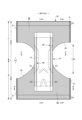
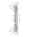
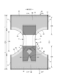
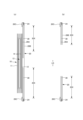
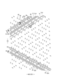
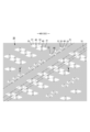
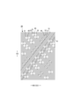
- FIG. 2 is a plan view (inner surface side) of the underpants-type disposable diaper in an unfolded state; 1 is a plan view (outer surface side) of a pants-type disposable diaper in an unfolded state; FIG. FIG. 2 is a plan view showing only the essential parts of the underpants-type disposable diaper in an unfolded state; (a) is a cross-sectional view taken along line CC of FIG. 1, and (b) is a cross-sectional view taken along line EE of FIG. FIG. 2 is a cross-sectional view taken along the line AA of FIG. 1; FIG. 2 is a cross-sectional view taken along the line BB of FIG.
- FIG. 1 is a plan view (outer surface side) of a pants-type disposable diaper in an unfolded state;
- FIG. (a) is a cross-sectional view taken along line CC of FIG. 7, and
- (b) is a cross-sectional view taken along line EE of FIG.
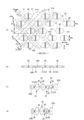
- (a) is a plan view of the main part of the elastic region,
- (b) is a cross-sectional view taken along line DD of (a),
- (c) is a cross-sectional view of the worn state, and
- (d) is a cross-sectional view of the natural length state.
- 4A and 4B are plan views showing various shapes of joints;
- FIG. FIG. 10 is a plan view of the stretchable region in an unfolded state;
- FIG. 4 is a plan view showing an enlarged main part of the stretchable region in the unfolded state;
- FIG. 4 is a plan view showing an enlarged main part of the elastic region in a natural length state;
- (a) is a cross-sectional view taken along the line DD of FIG. 12, and
- (b) is a cross-sectional view in a natural length state.
- FIG. 10 is a plan view of the stretchable region in an unfolded state;
- FIG. 4 is a plan view showing an enlarged main part of the stretchable region in the unfolded state;
- FIG. 4 is a plan view showing an enlarged main part of the elastic region in a natural length state;
- FIG. 10 is a plan view of the stretchable region in an unfolded state;
- FIG. 4 is a plan view showing an enlarged main part of the stretchable region in the unfolded state;
- FIG. 4 is a plan view showing an enlarged main part of the elastic region in a natural length state;
- FIG. 4 is a cross-sectional view schematically showing a cross-section of a principal part of an exterior body elongated to some extent;
- FIG. 4 is a cross-sectional view schematically showing a cross-section of a principal part of an exterior body elongated to some extent;
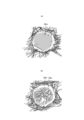
- (a) A trace diagram of a plane photograph of a joint formed in a first welding mode,
- (b) A trace diagram of a plane photograph of a joint formed in a third welding mode.
- 1 is a schematic diagram of an ultrasonic sealing device;
- FIG. FIG. 4 is a plan view showing an enlarged main part of the elastic region in a natural length state;
- FIG. 4 is a plan view showing an enlarged main part of the stretchable region in the unfolded state;
- FIG. 4 is a cross-sectional view schematically showing an elastic sheet elastic structure; (a) is a plan view of the essential part of the non-stretchable region, (b) is a cross-sectional view taken along line DD of (a), (c) is a cross-sectional view of the worn state, and (d) is a cross-sectional view of the natural length state.
- FIG. 4 is a plan view of the main part of the non-stretchable region;
- the dotted pattern portion in the drawing indicates an adhesive as a bonding means for bonding each constituent member positioned on the front side and the back side thereof.
- the adhesive can be applied, for example, by solid, bead, curtain, summit or spiral application of hot melt adhesive, or by pattern coating (transfer of hot melt adhesive in letterpress mode).
- the fixing portion of the elastic member can use a hot-melt adhesive applied to the outer peripheral surface of the elastic member, such as a comb gun or Surewrap application.
- Hot-melt adhesives include, for example, EVA-based, adhesive rubber-based (elastomer-based), polyolefin-based, polyester/polyamide-based, and the like, and can be used without particular limitation.
- a joining means for joining each constituent member a means by material welding such as heat sealing or ultrasonic sealing can be used.
- nonwoven fabric in the following description, a known nonwoven fabric can be appropriately used depending on the site and purpose.
- Constituent fibers of non-woven fabrics include, for example, polyolefin-based fibers such as polyethylene or polypropylene, polyester-based synthetic fibers such as polyamide-based fibers (including composite fibers such as core-sheath fibers in addition to single-component fibers), as well as recycled rayon and cupra. Fibers, natural fibers such as cotton, etc., can be selected without particular limitation, and these can also be mixed and used. In order to increase the softness of the nonwoven fabric, it is preferable to use crimped fibers as the constituent fibers.
- nonwoven fabrics are generally classified into short fiber nonwoven fabrics, long fiber nonwoven fabrics, spunbond nonwoven fabrics, meltblown nonwoven fabrics, spunlace nonwoven fabrics, thermal bonded (air-through) nonwoven fabrics, and needle punched nonwoven fabrics, depending on the fiber length, sheet forming method, fiber bonding method, and laminate structure.
- Laminated nonwoven fabrics are manufactured as a single nonwoven fabric containing all layers, and all layers have undergone a fiber bonding process, and multiple nonwoven fabrics manufactured separately are pasted together by a joining means such as a hot-melt adhesive. Does not include matching items.
- the pants-type disposable diaper (hereinafter also simply referred to as a diaper) of the illustrated example has an exterior body 20 that constitutes at least a waist region T, and an interior body 10 fixed to the exterior body 20.
- the absorbent body 13 is built in the body 10.
- the inner body 10 and the outer body 20 are joined to the front body F and the back body B. is folded in the center of the front-back direction LD (longitudinal direction), which is the boundary of the waist opening and a pair of left and right
- the pants-type disposable diaper is formed with leg openings.
- the back body B of the illustrated example has a pair of first portions B1 facing the left and right rear buttock points (vertices of the swelling of the buttocks) and the center in the width direction WD. It has a second portion B2 located in a range facing the gluteal cleft on the center line passing through. The back body B also has a third portion B3 located in a range facing the sacrum on the center line passing through the center in the width direction WD.
- the positions of the first portion B1, the second portion B2 and the third portion B3 can be appropriately determined according to the dimensional design of the product.
- the edge of the waist opening of the front body F is set to 0%
- the edge of the waist opening of the back body B is set to 100% in the unfolded state in which the side seals 21 are cut along the edge on the center side. %, it can be positioned within the range of 50 to 80%.
- the first portion B1 is in the unfolded state of the product (the state in which the one side seal 21 and the other side seal 21 are gripped and stretched to the maximum stretch in the width direction WD), and the one side seal 21 of the back body B Assuming that the side edge is 0% and the side edge of the other side seal 21 is 100%, it can be positioned within a range of 20 to 40% and a range of 60 to 80%, respectively.
- the position of the first portion B1 in the width direction WD can also be on both side edges of the absorbent body 13 .
- the edge of the waist opening of the front body F is set to 0%, and the edge of the waist opening of the back body B is set to 100% in the unfolded state in which the side seals 21 are cut along the edge on the central side. Then, it can be a portion from the 50% to 70% position to the 60% to 80% position.
- the edge of the waist opening of the front body F is set to 0%, and the edge of the waist opening of the back body B is set to 100% in the unfolded state in which the side seals 21 are cut along the edge on the central side. Then, it can be a portion from the 60% to 80% position to the 70% to 90% position.
- the inner body 10 has a structure in which an absorbent body 13 is interposed between a liquid-permeable top sheet 11 and a liquid-impermeable sheet 12 made of polyethylene or the like.
- the top sheet 11 absorbs and retains excretions that have permeated through the top sheet 11 .
- the planar shape of the interior body 10 is not particularly limited, it is generally rectangular as shown in FIG.
- a perforated or non-perforated nonwoven fabric, a perforated plastic sheet, or the like is preferably used as the top sheet 11 covering the front side (skin side) of the absorbent body 13.
- a liquid-impermeable plastic sheet such as polyethylene or polypropylene
- a microporous sheet obtained by melting and kneading an inorganic filler in an olefin resin such as polyethylene or polypropylene to form a sheet and then stretching the sheet in a uniaxial or biaxial direction can be preferably used.
- the absorber 13 is a known one, for example, a pile of pulp fibers, an aggregate of filaments such as cellulose acetate, or a non-woven fabric, optionally mixed or fixed with a superabsorbent polymer. can be used.
- the absorber 13 can be wrapped with a liquid-permeable and liquid-retaining wrapping sheet 14 such as crepe paper, if necessary, for shape and polymer retention.
- the absorbent body 13 is provided so as to extend from the front body F to the back body B.
- the absorbent body 13 extends further rearward than the pair of first portions B1 facing the rear buttock points on the left and right sides, and both side edges of the absorbent body 13 are formed by the first portion B1 and the second portion in the back body B. It preferably extends through a position spaced outward in the width direction WD from a line segment connecting the front end of B2 (a portion of the center line passing through the center in the width direction WD that is located in a range facing the gluteal cleft).
- the absorber 13 extends further rearward than the front end of the third portion B3 facing the sacrum, and both side edges of the absorber 13 are spaced outward in the width direction WD from both side edges of the third portion B3. It is preferable to have
- the shape of the absorber 13 is preferably formed in a substantially hourglass shape with a constricted portion 13N narrower in width than the front and rear sides in the crotch portion, but may be in another shape such as a rectangle.
- the size of the constricted portion 13N can be determined as appropriate, but the length in the front-rear direction of the constricted portion 13N can be about 20 to 50% of the total length of the diaper, and the width of the narrowest portion is equal to the total width 13w of the absorbent body 13. It can be about 40 to 60%.
- the inner body 10 has such a constricted portion 13N
- the planar shape of the inner body 10 is substantially rectangular, a portion of the inner body 10 corresponding to the constricted portion 13N of the absorbent body 13 does not have the absorbent body 13.
- Absorber side portions 17 are formed.
- the liquid-impermeable sheet 12 is folded back on both sides in the width direction of the absorbent body 13 together with the top sheet 11, but it may extend on both sides in the width direction of the absorbent body 13. It may be spaced from both side edges of the body 13 toward the center in the width direction.
- the liquid-impermeable sheet 12 it is desirable to use an opaque sheet so that the brown color of feces and urine does not appear.
- a film obtained by internally adding a pigment or filler such as calcium carbonate, titanium oxide, zinc oxide, white carbon, clay, talc, or barium sulfate to a plastic is preferably used.
- the three-dimensional gathers 90 include a fixing portion 91 fixed to the side portion of the back surface of the inner body 10, and the inner body 10 extending from the fixing portion 91 to the side of the inner body 10. and the front and rear ends of the body portion 92 are attached to the side portions of the surface of the interior body 10 (the top sheet 11 in the illustrated example) with a hot melt adhesive 95b or the like. It has a fixed lying down portion 93 and a free portion 94 between which the lying down portion 93 is not fixed.
- Each of these parts is formed by a gather sheet 95 formed by folding a sheet of nonwoven fabric or the like into a double sheet.
- the gathered sheet 95 is attached over the entire front-to-rear direction of the inner body 10 , the fallen portions 93 are provided on the front and rear sides of the non-absorbent side portion 17 , and the free portions 94 are on both front and rear sides of the non-absorbent side portion 17 .
- a gather elastic member 96 is arranged at the tip of the free portion 94 or the like between the double gather sheets 95 .
- the gather elastic member 96 is for raising the free portion 94 by elastic contraction force as shown in FIG. 5 in the product state.
- the fixing structure of the gathering elastic member 96 and the gathering sheet 95 is not particularly limited.
- the gathering elastic member 96 is adhesively fixed to the gathering sheet 95 and the facing surface of the gathering sheet 95 is joined, there is no hot-melt adhesive at the position of the gathering elastic member 96 in the lodged portion 93, and therefore the gathering elasticity is reduced.
- a structure in which the member 96 and the gather sheet 95 are not adhered to each other and the facing surface of the gather sheet 95 is not joined at the position where the gather elastic member 96 is provided can be employed.
- the gather elastic member 96 commonly used materials such as styrene rubber, polyolefin rubber, urethane rubber, ester rubber, polyurethane, polyethylene, polystyrene, styrene butadiene, silicone, and polyester can be used. Also, in order to make it difficult to see from the outside, it is preferable to set the thickness to 925 dtex or less, the tension to 150 to 350%, and the interval to 7.0 mm or less. As the gather elastic member 96, a tape-like member having a certain width can be used in addition to the elongated shape as shown in the drawing.
- the gather sheet 95 Although various nonwoven fabrics can be used as the gather sheet 95, it is particularly preferable to use a nonwoven fabric having a reduced basis weight and excellent breathability in order to prevent stuffiness. Furthermore, the gather sheet 95 is coated with a silicone, paraffin metal, or alkylchromic chloride water repellent agent to prevent permeation of urine and the like, prevent rashes, and improve the touch (dry feeling) to the skin. It is desirable to use a water-repellent nonwoven fabric coated with
- the back surface of the inner body 10 is joined to the inner surface of the outer body 20 in the inner body fixing region 10B (hatched region) with a hot-melt adhesive or the like.
- the inner body fixing region 10B can be determined as appropriate, and can be substantially the entire inner body 10. However, it is preferable that both ends in the width direction of the inner body 10 are not fixed to the outer body 20. FIG.
- the outer body 20 constitutes at least the waist regions T of the front body F and the back body B.
- the intermediate region L which is the range in the front-rear direction between the waist region T of the front body F and the waist region T of the back body B, is further provided. One of them may not have the intermediate region L.
- the side edge of the exterior body 20 may be located at the center side in the width direction from the side edge of the interior body 10 at the crotch portion as shown in the illustrated example, or may be located outside in the width direction.
- a portion of the outer body 20 located in the waist area T can be divided into a waist end portion 23 forming an end portion on the waist opening side and a waist lower portion U which is a portion below this.
- the portion of the outer body 20 located in the waist region T has a boundary where the elastic force in the width direction WD changes (for example, a boundary where the type of elastic member, thickness, thickness, elongation rate, etc. changes)
- the waist end portion 23 is located on the waist opening side of the boundary located closest to the waist opening side, and if there is no such boundary, the waist end portion 23 is the portion that extends from the absorbent body 13 or the inner body 10 toward the waist opening side.
- the length of these portions in the front-rear direction LD can be appropriately determined according to the size, type, etc. of the product.
- the outer body 20 can be provided with an elastic member at a suitable location to form an elastic region 80 that elastically expands and contracts together with the elastic member.
- the stretchable region 80 shrinks with the contraction of the elastic member in the natural length state, and wrinkles or folds are formed.
- an elastic sheet 30 such as an elastic film or a nonwoven fabric made of elastomer fibers can be used without particular limitation, in addition to known elongated elastic members such as filaments and belts.
- the stretchable region 80 is preferably provided in each of the waist end portion 23, the waist lower portion U, and the portion located in the intermediate region L.
- the elastic region 80 can be partially omitted, such as in the middle of the front-rear direction LD.
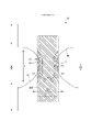
- the elastic sheet 30 is interposed, and as shown in FIG. 9, the first sheet layer 20A and the second sheet layer 20B penetrate the elastic sheet 30 at a number of joints 40 arranged at intervals. It has an elastic sheet expansion structure 20X joined through a joint hole 31 .
- the region having the elastic sheet elastic structure 20X is contracted in the width direction due to contraction of the elastic sheet 30 and is stretchable in the width direction (that is, the elastic direction ED becomes the width direction WD of the diaper). has 80.
- the planar shape of the exterior body 20 is formed by concave leg circumference lines 29 so that the width direction side edges of the portion located in the intermediate region L each form leg openings, and the overall shape resembles an hourglass. ing.
- the outer body 20 may be formed separately from the front body F and the back body B, and the two may be arranged so as to be separated from each other in the front-rear direction LD of the diaper at the crotch portion.
- the configuration shown in FIGS. 1 and 2 is a configuration in which the elastic sheet elastic structure 20X extends to the waist edge 23. However, if the elastic sheet elastic structure 20X is used for the waist edge 23, the waist edge 23 can be stretched. If necessary, such as insufficient tightening, the elastic sheet stretchable structure 20X is not provided at the waist end 23 as shown in FIGS. Structures can also be provided.
- the waist elastic member 24 is an elongated elastic member such as a plurality of thread rubbers arranged at intervals in the front-rear direction LD, and provides elastic force so as to tighten the circumference of the body.
- the waist elastic members 24 are not arranged substantially as a bundle with close intervals, but three or more at intervals of about 3 to 8 mm in the front-rear direction so as to form a predetermined elastic zone. , preferably five or more.
- the elongation rate of the waist elastic member 24 when fixed can be determined as appropriate, it can be about 230 to 320% in the case of normal adult use.
- the waist elastic member 24 uses thread rubber, but other elongated stretchable members such as flat rubber may be used.
- an elastic sheet 30 may be provided at the waist end 23, and an elongated waist elastic member 24 may be provided at a position overlapping the elastic sheet 30, so that both elastic members may be used to form a stretchable structure.
- the edge portion of the leg opening in the exterior body 20 is not provided with an elongated elastic member extending along the leg opening.
- An elongated elastic member may be provided instead of the elastic sheet 30 of the part.
- the intermediate region L may not be provided with the elastic sheet stretchable structure 20X, or the waist region T of the back body B may be formed from the waist region T of the front body F via the intermediate region L.
- Appropriate deformation is also possible, such as providing the elastic sheet stretchable structure 20X continuously in the front-back direction LD to the inside, or providing the elastic sheet stretchable structure 20X only in one of the front body F and the back body B. .
- a region having the elastic sheet stretchable structure 20X in the exterior body 20 has a stretchable region 80 that is stretchable in the width direction WD.
- the stretchable region 80 is contracted in the width direction WD due to the shrinkage force of the elastic sheet 30 and is expandable in the width direction WD. More specifically, in a state in which the elastic sheet 30 is stretched in the width direction WD, the elastic sheet 30 is spaced apart in the width direction WD and in the front-rear direction LD (the direction LD orthogonal to the stretching direction ED).
- the first sheet layer 20A and the second sheet layer 20B are joined through the joining holes 31 of the elastic sheet layer 20A and the second sheet layer 20B to form a large number of joining portions 40, thereby forming the elastic sheet elastic structure 20X. remains uninterrupted in the width direction WD, and the contraction force of the elastic sheet 30 contracts the first sheet layer 20A and the second sheet layer 20B to form contraction folds 25.
- Such elasticity can be imparted by
- the stretchable region 80 swells in the direction in which the first sheet layer 20A and the second sheet layer 20B between the joints 40 are separated from each other in the natural length state.
- a contraction fold 25 extending in the LD is formed, and even in a mounted state in which it is stretched to some extent in the width direction WD, the contraction fold 25 is stretched but remains.
- the first sheet layer 20A and the second sheet layer 20B are not joined to the elastic sheet 30 at least at the joining portion 40 other than between the first sheet layer 20A and the second sheet layer 20B, As can be seen from FIG. 9C assuming the worn state and FIG.
- the maximum elongation in the width direction WD of the elastic region 80 is desirably 190% or more (preferably 200 to 220%).
- the maximum elongation of the elastic region 80 is substantially determined by the elongation rate of the elastic sheet 30 at the time of manufacture, but based on this, it decreases due to factors that inhibit contraction in the width direction WD.
- the main factor of such a hindrance is the ratio of the length L of the joint 40 per unit length in the width direction WD, and the larger the ratio, the lower the maximum elongation. Normally, since the length L of the joint 40 has a correlation with the area ratio of the joint 40 , the maximum elongation of the stretchable region 80 can be adjusted by the area ratio of the joint 40 .
- the elastic sheet 30 When the elastic sheet 30 has a portion 32 that continues linearly along the width direction WD as in the example shown in FIG. It can be adjusted by summing the orthogonal dimension 32w (equal to the interval 31d between the joint holes 31) of the linearly continuous portion 32 (see FIG. 9A) along the direction WD.
- the stretching stress of the stretchable region 80 is It can be adjusted by the crossing angle formed by the continuous direction of the unbonded bands 51 and 52 in which the portions without the bonded portion 40 are continuous and the stretching direction ED. It is preferable that the acute side crossing angles ⁇ 1 and ⁇ 2 formed with the direction ED are larger than 0 degree and 45 degrees or less, particularly in the range of 10 to 30 degrees.
- the area ratio of the joints 40 in the stretchable region 80 and the area of the individual joints 40 can be determined as appropriate, but in general, it is preferable to set them within the following range.
- Area of joint 40 0.14 to 3.5 mm 2 (especially 0.14 to 1.0 mm 2 )
- Area ratio of joint 40 1.8 to 19.1% (especially 1.8 to 10.6%)
- the maximum elongation and elongation stress of the stretchable region 80 can be adjusted by the area of the joint 40. Therefore, as shown in FIG. The fit can be changed according to the part.
- the edge region 81 of the leg opening has a higher area ratio of the joint 40 than the rest of the stretchable region 80, and therefore has a weaker elongation stress and becomes a flexibly stretchable region.
- the shapes of the individual joints 40 and joint holes 31 in their natural length state can be determined as appropriate, but may be circular, elliptical, triangular, rectangular (see FIGS. 9, 11, and 15), or rhombic (see FIG. 10). (b)), convex lens shape (see FIG. 10(a)), concave lens shape (see FIG. 10(c)), star shape, cloud shape, or any other shape.
- the dimensions of the individual joints 40 are not particularly limited, but the maximum length 40y (approximately equal to the orthogonal dimension 31y of the joint hole 31) is 0.5 to 3.0 mm, particularly 0.7 to 1.1 mm. and the maximum width 40x is preferably 0.1 to 3.0 mm, especially 0.1 to 1.1 mm in the case of a shape elongated in the direction XD perpendicular to the stretching direction ED.
- the arrangement pattern of the joints 40 of the stretchable region 80 is not particularly limited, and any pattern (see, for example, Patent Documents 1 to 8) can be adopted.
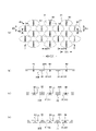
- non-bonded bands 51 and 52 in which portions having no bonded portion 40 are continuous exist in an oblique grid pattern.
- the illustrated example shows a particularly preferable example.
- the first non-bonded bands 51 linearly continuous along the first direction 51d intersecting the side crossing angle ⁇ 1) are repeatedly present at intervals in the direction orthogonal to the first direction 51d.
- a large number of joint portions 40 and joint holes 31 are provided at intervals between adjacent first non-joint bands 51 in the stretchable region 80 .
- the unit structure including a plurality of first non-bonded bands 51 having different first widths 51w determined as the width in the direction orthogonal to the first direction 51d is orthogonal to the first direction 51d in the elastic region 80. Repeatedly exist in the direction.
- the unit structure described above is not limited by the size of the width 51w as long as it includes a plurality of first non-bonded bands 51 having different first widths 51w.
- the width 51w is preferably 1.2 to 60 times the width of the first non-bonded strip 51 having the nearest width 51w, and preferably 0.01 to 0.8 times the width 51w.
- the unit structure described above may have different first widths 51w in all the first non-bonded bands 51 as long as it includes a plurality of first non-bonded bands 51 with different first widths 51w.
- the first width 51w of some first non-bonded strips 51 may be different from the first width 51w of the other single or multiple first non-bonded strips 51. As shown in FIG.
- the maximum value of the first width 51w in the first non-bonded band 51 is the maximum value of the widths in the direction perpendicular to the continuous direction in all the non-bonded bands 51 and 52 that are different in inclination direction and common.
- the maximum value of the first width 51w in the first non-bonded band 51 can be determined as appropriate, but it is preferably 1.2 to 60 times the first non-bonded band 51 with the nearest width 51w. preferable.
- the width of all the non-bonded bands 51 and 52 including the first non-bonded band 51 is not limited in the direction perpendicular to the continuous direction, but it is usually within the range of 0.02 to 5 mm. is preferred. Needless to say, the width of the non-bonded bands 51 and 52 in the direction perpendicular to the direction of continuation is the first width 51w of the first non-bonded band 51, which is a linearly continuous portion. So it is monospaced.
- a first interval 51s which is defined as the interval in the direction orthogonal to the first direction 51d between adjacent first non-bonded bands 51, can be determined as appropriate. Therefore, the first spacing 51s may be the same as, wider, or narrower than the first width 51w of the adjacent first non-bonded bands 51 . As one preferable example, the maximum value of the first width 51w in the first non-bonded band 51 in the unit structure is smaller than the maximum value of the first spacing 51s.
- the maximum value of the first width 51w in the first non-bonded band 51 can be determined as appropriate, but is preferably 0.01 to 9 times the maximum value of the first spacing 51s.
- the interval in the direction perpendicular to the continuous direction in all the non-bonded bands 51 and 52 including the first non-bonded band 51 is not particularly limited, but is usually within the range of 0.3 to 50 mm. is preferred. Needless to say, the interval in the direction orthogonal to the continuous direction in the non-bonded bands 51 and 52 is the first interval 51s in the first non-bonded band 51, and is equal to the continuous direction. .
- non-bonded bands 51 and 52 are linearly continuous along a second direction 52d that intersects the stretch direction ED at an acute angle (acute side crossing angle ⁇ 2) other than the first direction 51d.
- the two no-bonded bands 52 may be repeatedly present at intervals in the direction orthogonal to the second direction 52d, or the second no-bonded bands 52 may not exist.
- One preferred form having the second non-bonded band 52 is that the elastic region 80 has the non-bonded bands 51 and 52 formed in a slanted lattice pattern, and the first non-bonded band 51 is formed in a slanted lattice-like non-bonded band.
- the first direction 51d and the second direction 52d have opposite positive and negative inclinations with respect to the expansion/contraction direction ED.
- the acute side crossing angles ⁇ 1 and ⁇ 2 with respect to the stretching direction ED of the first direction 51d and the second direction 52d are respectively 5 to 45 degrees, particularly 10 to 30, so that the stretchability in the stretchable region 80 is sufficiently ensured. can be done.
- the oblique striped pattern along the oblique direction of the second non-bonded band 52 is more strongly visible in the same elastic region 80, the contiguous folds 25 of the first non-bonded band 51 and the continuous portion of the elastic sheet 30 therein There is a risk that the oblique stripe pattern due to Therefore, when the second non-bonded band 52 is provided as in the example shown in FIG. Alternatively, it is desirable to arrange the joint portion 40 so as not to have the second non-joint band 52 . As a result, in the stretchable region 80 , the oblique striped pattern formed by the contraction folds 25 of the first non-bonded band 51 and the continuous portion of the elastic sheet 30 therein becomes more visible.
- the joints 40 are aligned in the first direction 51d between the adjacent first non-bonded bands 51.
- the acute crossing angle ⁇ 3 in the longitudinal direction with respect to the direction perpendicular to the It is preferable because a larger dimension in the direction of stretching ED can be ensured and deterioration of stretchability can be suppressed.
- the unit structure includes a wide first non-bonded band 51 having a maximum first width 51w and a narrow first non-bonded band 51 having a narrower first width 51w.
- the acute crossing angle in the longitudinal direction with respect to the second direction 52d is within 5 degrees
- the elongated joints 40 having a maximum dimension 40f in a direction perpendicular to the longitudinal direction of 0.1 to 0.4 mm are aligned in the first direction 51d at intervals.
- the acute crossing angle ⁇ 3 in the longitudinal direction with respect to the first direction 51d is 45 degrees or more, and the maximum dimension 40g in the direction orthogonal to the longitudinal direction is 0.00.
- the elongated joints 40 of 1 to 0.4 mm are aligned in the first direction 51d at intervals. Due to the shape and arrangement of the joints 40, the constriction folds 25 of the first non-bonded band 51 and the continuation of the elastic sheet 30 therein are particularly visually emphasized with a smaller area of the joints 40. become.
- the row of the joints 40 located between the adjacent non-bonded bands 51 and 52 may be one row or multiple rows.
- the intervals between the joints 40 in the row direction be regular, not all the intervals need to be constant, and some intervals may be different.
- a non-stretchable region 70 can be provided on at least one widthwise side of the stretchable region 80 in the region having the elastic sheet stretchable structure 20X in the exterior body 20, as shown in FIG.
- the non-stretchable region 70 means that the maximum elongation in the stretching direction ED is 120% or less.
- the maximum elongation of the non-stretchable region 70 is preferably 110% or less, more preferably 100%.
- the arrangement of the stretchable regions 80 and the non-stretchable regions 70 can be determined as appropriate.
- the portion overlapping the absorbent body 13 is a region that does not require high elasticity.
- non-stretchable region 70 entirely (preferably including substantially the entire inner body fixing region 10B).
- the non-stretchable region 70 can be provided from the region overlapping the absorbent body 13 to the region not overlapping the absorbent body 13 located in the width direction WD or the front-rear direction LD, and only the non-stretchable region in the region not overlapping the absorbent body 13. 70 can also be provided.
- each joint 40 in the non-stretchable region 70 is not particularly limited, and can be appropriately selected from the same shapes as those described in the section on the stretchable region 80 .
- the area ratio of the joints 40 in the non-stretchable region 70 and the area of the individual joints 40 can be determined as appropriate. This is preferable because the non-stretchable region 70 does not become hard due to the low area ratio of the portion 40 .
- Area of joint 40 0.10 to 0.75 mm 2 (especially 0.10 to 0.35 mm 2 )
- Area ratio of joint 40 4 to 13% (especially 5 to 10%)
- the non-stretchable region 70 can be formed by densely arranging the joints 40 so that the first sheet layer 20A and the second sheet layer 20B are not shrunk by the contractile force of the elastic sheet 30 and folds are not formed.
- Specific examples of methods for forming the non-stretchable region 70 include those described in Patent Documents 3 to 6, for example. 25 and 26 show an example of the non-stretchable region 70 described in Patent Document 6.
- the vent holes 33 are opened with substantially the same size in both the natural length state and the expanded state.
- the means for joining the first sheet layer 20A and the second sheet layer 20B in the joining portion 40 is not particularly limited.
- the first sheet layer 20A and the second sheet layer 20B may be joined at the joining portion 40 by a hot-melt adhesive, or by a joining means such as heat sealing or ultrasonic sealing, which is material welding.
- the joining portion 40 is formed by material welding.
- a first welding mode in which the first sheet layer 20A and the second sheet layer 20B are joined only by a melted and solidified material 20m of at least one of at least one of the second sheet layer 20A and the second sheet layer 20B (see FIG. 18(a))
- a second welding mode in which the first sheet layer 20A and the second sheet layer 20B are joined only by the melted and solidified material 30m of the elastic sheet 30 in the joining portion 40
- a third welding mode see FIG. 18(c) in which both of these are combined, but the second and third welding modes are preferable.
- the first sheet layer 20A is formed by the melted and solidified material 20m of a part of the first sheet layer 20A and the second sheet layer 20B and the melted and solidified material 30m of all or most of the elastic sheet 30 at the joint 40. and the second sheet layer 20B are joined.
- the elastic sheet 30 shown in white is placed between the melted and solidified fibers 20m of the first sheet layer 20A or the second sheet layer 20B shown in black.
- the elastic sheet 30 is between the melted and solidified fibers 20m of the first sheet layer 20A or the second sheet layer 20B. cannot be seen.
- the first sheet layer 20A and the second sheet layer 20B are bonded to each other by using the molten and solidified material 20m of at least one of the first sheet layer 20A and the second sheet layer 20B as an adhesive.
- the sheet layer 20B it is preferable that a part of the first sheet layer 20A and the second sheet layer 20B is not melted so that the joining portion 40 is not hardened.
- the core (composite) of all the fibers of the joint portion 40 must be partially melted. Including not only the core of the fiber but also the central part of the monocomponent fiber) remains, but the surrounding part (including not only the sheath of the composite fiber but also the surface layer of the monocomponent fiber) is melted, and some fibers does not melt at all, but the rest of the fiber melts entirely, or the core remains but its surrounding portion melts.
- the peel strength is high.
- the first sheet layer 20A and the second sheet layer 20B are joined using the melted and solidified material 30m of the elastic sheet 30 as an adhesive like the second welding mode and the third welding mode, the peel strength is high.
- the second welding mode under the condition that the melting point of at least one of the first sheet layer 20A and the second sheet layer 20B is higher than the melting point of the elastic sheet 30 and the heating temperature for forming the joint 40, the first sheet layer 20A and It can be produced by sandwiching the elastic sheet 30 between the second sheet layers 20B, applying pressure and heat to the joint portion 40, and melting only the elastic sheet 30. As shown in FIG.
- the melting point of at least one of the first sheet layer 20A and the second sheet layer 20B is higher than the melting point of the elastic sheet 30, It can be produced by sandwiching the elastic sheet 30 and applying pressure and heat to the part that will become the joint 40 to melt at least one of the first sheet layer 20A and the second sheet layer 20B and the elastic sheet 30 .
- the melting point of the elastic sheet 30 is preferably about 80 to 145.degree. C., and the melting points of the first sheet layer 20A and the second sheet layer 20B are about 85 to 190.degree. is preferable, and the difference between the melting point of the first sheet layer 20A and the second sheet layer 20B and the melting point of the elastic sheet 30 is preferably about 60 to 90.degree. Also, the heating temperature is preferably about 100 to 150.degree.
- the melted and solidified material 30m of the elastic sheet 30 is bonded to the joint 40 as shown in FIG. 19(c). It may penetrate between the fibers throughout the thickness direction of the first sheet layer 20A and the second sheet layer 20B in FIG. As shown in 19(b), the flexibility of the joint 40 is higher in the form in which the fibers hardly permeate between the fibers of the first sheet layer 20A and the second sheet layer 20B.
- FIG. 21 shows an example of an ultrasonic sealing device suitable for forming the second welded form and the third welded form.
- this ultrasonic sealing device when forming the bonding portion 40, the first sheet layer 20A and the elastic sheet are placed between the anvil roll 60 having the protrusions 60a formed on the outer surface in the pattern of the bonding portion 40 and the ultrasonic horn 61. 30 and second sheet layer 20B are fed.
- the feed drive roll 63 and the nip roll 62 are made slower than the transfer speed after the anvil roll 60 and the ultrasonic horn 61, the feed drive roll 63 and the nip roll 62
- the elastic sheet 30 is stretched to a predetermined elongation rate in the MD direction (machine direction, flow direction) along the path from the nip position by the anvil roll 60 and the ultrasonic horn 61 to the seal position by the ultrasonic horn 61 .
- the elongation rate of the elastic sheet 30 can be set by selecting the speed difference between the anvil roll 60 and the feeding drive roll 63, and can be set to about 300% to 500%, for example.
- the first sheet layer 20A, the elastic sheet 30 and the second sheet layer 20B sent between the anvil roll 60 and the ultrasonic horn 61 are laminated in this order, and the protrusion 60a and the ultrasonic horn 61 While applying pressure between them, they are heated by the ultrasonic vibration energy of the ultrasonic horn 61 to melt only the elastic sheet 30, or to melt at least one of the first sheet layer 20A and the second sheet layer 20B and the elastic sheet 30.
- the first sheet layer 20A and the second sheet layer 20B are joined through the joint hole 31 at the same time as the joint hole 31 is formed in the elastic sheet 30 . Therefore, in this case, the area ratio of the joint portion 40 can be selected by selecting the size, shape, spacing, and arrangement pattern of the protrusions 60a of the anvil roll 60 in the roll length direction and the roll circumferential direction. can.
- the portions of the elastic sheet 30 corresponding to the projections 60a of the anvil roll 60 melt and separate from the surroundings, thereby forming the holes.
- the portions of the elastic sheet 30 between adjacent joint holes 31 aligned in the stretch direction ED are formed on both sides of the stretch direction ED by the joint holes 31, as shown in FIGS. Since it is cut from the part and loses the support on both sides in the shrinking direction, the center side of the stretching direction ED is closer to the center side of the direction LD orthogonal to the stretching direction ED within the range where continuity in the direction orthogonal to the shrinking direction can be maintained. , and the joint hole 31 expands in the expansion/contraction direction ED.
- the constituent materials of the first sheet layer 20A and the second sheet layer 20B can be used without any particular limitation, but preferably have air permeability. Therefore, it is preferable to use a nonwoven fabric from these points of view and the point of view of softness. When a non-woven fabric is used, it is preferable that its basis weight is about 10 to 25 g/m 2 . Also, part or all of the first sheet layer 20A and the second sheet layer 20B may be a pair of layers formed by folding one sheet of material and facing each other. For example, as shown in the illustrated embodiment, in the waist end portion 23, the second sheet layer 20B is used as the outer component, and the first sheet layer 20A is used as the folded portion 20C that is folded inward at the waist opening edge.
- the elastic sheet 30 is interposed therebetween, and in the other portions, the inner component is the first sheet layer 20A, the outer component is the second sheet layer 20B, and the elastic sheet 30 is interposed therebetween. can intervene.
- the constituent members of the first sheet layer 20A and the constituent members of the second sheet layer 20B are separately provided over the entire front-rear direction LD, and the constituent members of the first sheet layer 20A and the second sheet layer 20B are arranged without folding back the constituent members.
- An elastic sheet 30 can also be interposed between the components of layer 20B.
- the elastic sheet 30 is not particularly limited, and may be an elastic film or a stretchable nonwoven fabric as long as it is a thermoplastic resin sheet that itself has elasticity. Moreover, as the elastic sheet 30, in addition to the non-perforated one, the one formed with a large number of holes or slits for ventilation can be used.
- the tensile strength in the width direction WD is 8 to 25 N / 35 mm
- the tensile strength in the front-back direction LD is 5 to 20 N / 35 mm
- the width The elastic sheet 30 preferably has a tensile elongation of 450 to 1050% in the direction WD and a tensile elongation of 450 to 1400% in the longitudinal direction LD.
- the thickness of the elastic sheet 30 is not particularly limited, it is preferably about 20 to 40 ⁇ m.
- stretchable structure with elongated elastic members A part or all of the stretchable region 80 and the non-stretchable region 70 in the exterior body 20, and the gluteal cleft stretchable region 82 and the sacral stretchable region 83 described later are different from this example and have elongated elastic properties similar to those described in Patent Document 2. It can also be provided using a member.
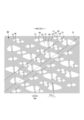
- the back body B is provided with a gluteal cleft elastic region 82 containing a gluteal cleft elastic member (the elastic sheet 30 in the illustrated example).
- the gluteal cleft stretchable region 82 is a region that extends on both sides in the width direction WD of the second portion B2, and whose both side edges are separated from the imaginary straight line along the front-rear direction LD passing through the first portion B1 toward the center side in the width direction WD.
- the position of the gluteal cleft elastic region 82 changes depending on the dimensional design of the product, but in normal cases, for example, it can be determined as follows. That is, when the edge of the waist opening of the front body F is set to 0% and the edge of the waist opening of the back body B is set to 100% in the unfolded state in which the side seals 21 are cut along the edge on the central side, the gluteal cleft stretches.
- the area 82 can be provided from the 50-70% position to the 60-80% position.
- the side edge of one side seal 21 of the back body B is set to 0%.
- the gluteal cleft elastic region 82 can be provided from a position of 40% to 60% to a position of 50% to 70%.
- regions adjacent to both sides of the gluteal cleft elastic region 82 in the width direction WD are non-stretchable regions 70, but the maximum elongation of the gluteal cleft elastic region 82 in the width direction WD is the gluteal cleft elastic region 82.
- the regions adjacent to both sides in the width direction WD of the gluteal cleft stretchable region 82 may be the stretchable regions 80 as long as the regions are larger than the maximum stretch in the width direction WD of the regions adjacent to both sides in the width direction WD.
- the waist opening side and the crotch side of the gluteal cleft stretchable region 82 are the non-stretchable region 70 in the illustrated example, but one or both of them may be the stretchable region 80 .
- the maximum elongation in the width direction WD of the gluteal cleft elastic region 82 can be determined as appropriate, it is usually preferably about 120 to 200%.
- the single elastic sheet stretchable structure 20X allows the gluteal cleft stretchable region 82 to be adjacent to both sides of the gluteal cleft stretchable region 82 in the width direction WD and wider than both side edges of the absorber 13.
- the maximum elongation in the width direction WD of the non-stretchable region 70 is less than 120%, and the maximum elongation of the gluteal cleft stretchable region 82 is 1.5 to 3 times the maximum elongation in the width direction WD of the non-stretchable region 70.
- the maximum elongation of the side stretchable regions 80 is preferably two to five times the maximum elongation of the non-stretchable regions 70 in the width direction WD.
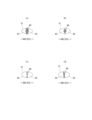
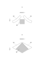
- the gluteal cleft elastic region 82 may have a rectangular shape with a pair of sides along the front-rear direction LD and a pair of sides along the width direction WD, or may 23(a) and 23(b); And as shown in FIG. 24(b), it consists of a front portion that widens toward the rear side and a rear portion that narrows toward the rear side, and diagonal lines along the front-back direction LD and crossing each other. A quadrangular shape having a diagonal line along the width direction WD or the like can be determined as appropriate.
- the gluteal cleft stretchable region 82 may have a shape surrounded by straight lines, or a shape surrounded by curved lines partially or entirely around the periphery.
- the elastic limit elongation of the gluteal cleft stretchable region 82 may be constant or varied throughout.
- the area ratio of the joint portion 40 decreases stepwise (or may be continuous) toward the center in the width direction WD.
- the contraction rate increases toward the center in the width direction WD, and the fit to the gluteal cleft is particularly excellent.
- the area ratio of the joints 40 in the central region 82A in the width direction WD is lower than the area ratio of the joints 40 in the side regions 82B located on both sides thereof (for example, 0.000). 1 to 0.9 times).
- the third portion B3 of the back body B is provided with a sacral elastic region 83 containing a sacral elastic member.
- regions adjacent to both sides of the sacral elastic region 83 in the width direction WD are non-stretchable regions 70 described later.
- the regions adjacent to both sides in the width direction WD of the sacrum stretchable region 83 may be the stretchable regions 80 as long as the regions are larger than the maximum stretch in the width direction WD of the regions adjacent to both sides in the width direction WD.
- the stretchable region 80 that extends across both side seals in the width direction is adjacent to the waist opening side of the sacral stretchable region 83 (that is, the stretchable region 80 is continuous to the waist opening side), although one side is the non-stretchable region 70, it may be reversed, and both may be the stretchable region 80 or the non-stretchable region 70.
- the position of the sacral stretchable region 83 changes depending on the dimensional design of the product, but in normal cases it can be determined, for example, as follows. That is, when the edge of the waist opening of the front body F is set to 0% and the edge of the waist opening of the back body B is set to 100% in the unfolded state in which the side seals 21 are cut along the edge on the central side, the sacral elastic region 83 can be provided from the 60-80% position to the 70-90% position. In addition, in the unfolded state of the product (the state where one side seal 21 and the other side seal 21 are gripped and stretched to the maximum stretch in the width direction WD), the side edge of one side seal 21 of the back body B is set to 0%. , When the side edge of the other side seal 21 is 100%, the sacral elastic region 83 can be provided from a position of 40% to 60% to a position of 50% to 70%.
- the maximum elongation of the sacrum elastic region 83 in the width direction WD can be determined as appropriate, and may be equal to the maximum elongation of the gluteal cleft elastic region 82 or may be greater or smaller than the maximum elongation of the gluteal cleft elastic region 82 .
- the shape of the sacral stretchable region 83 should be a shape that widens toward the rear side (for example, an isosceles triangle shape having a base along the width direction WD and an apex in front of the base along the width direction WD as in the example shown in FIG. 22). is preferable, but it can also be rectangular with a pair of sides along the front-rear direction LD and a pair of sides along the width direction WD similarly to the gluteal cleft elastic region 82 shown in FIG. 24(a).
- the sacral stretchable region 83 may have a shape in which part or all of the peripheral edge is surrounded by curved lines (for example, an arc shape in which both side edges are recessed toward the center in the illustrated example).
- the shape of the slot 100 can be appropriately determined according to the shape of the leg circumference of the pants-type disposable diaper and the arrangement of various elastic members.
- the slot 100 on one side of the gluteal cleft elastic region 82 and the slot 100 on the other side in the width direction WD may be connected to form one hole as shown in FIG. 22, FIG. 23(b), and FIGS. 24(a) and (b), the holes may not be connected and may be separate holes.
- the slot 100 may extend linearly (substantially rectangular), or may be as shown in Fig. 24(a). It may extend in a curved shape (including bending) so that the inclination with respect to the front-rear direction LD increases toward the rear side.
- the width 100w of the slot 100 (the dimension in the direction orthogonal to the extending direction of the slot) may be constant.
- the slot 100 may be shaped such that the width becomes narrower toward the rear side, for example, a triangular shape.
- the slots 100 are provided on both sides in the width direction WD of the gluteal cleft elastic region 82 in the absorbent body 13, the slots 100 are provided on each side as shown in FIGS. In addition to providing only one, as shown in FIG.
- the width 100w of the slot 100 may be determined as appropriate. As an example, it is preferable that the width 100w of the slot 100 is about 0.05 to 0.2 times the total width 13w of the absorbent body 13 .
- the direction 101 in which the slot 100 extends can be appropriately determined according to the shape of the leg circumference of the pants-type disposable diaper, the shape of the slot 100, and the arrangement of various elastic members. and the acute side crossing angle ⁇ 1 with the longitudinal direction LD is preferably 10 to 75°, particularly 30 to 60°. As an example, it is preferable that the extending direction 101 of the slot 100 and the line segment connecting the front ends of the first portion B1 and the second portion B2 are parallel.
- the direction 101 in which the slot 100 extends means the direction along the center line of the slot 100 . Further, when the direction in which the slot 100 extends is curved such as an arc shape, the direction in which the slot 100 extends means the direction along the tangential line of the center line of the slot 100 .
- the portions of both side edges of the gluteal cleft elastic region 82 where the slots 100 are positioned at least in the width direction WD extend parallel to the direction in which the slots 100 extend, the rearward movement of the leg is prevented. It is preferable because the absorber 13 is easily deformed so that the width of the slot 100 is particularly narrowed when a lifting force is applied.
- the positional relationship between the side edge of the gluteal cleft elastic region 82 and the slot 100 can be determined as appropriate, and may be separated or close (the distance between the side edge of the gluteal cleft elastic region 82 and the slot 100 is It is preferable that the distance between the side edge of the body 13 and the slot 100 is narrower than that, because the force is particularly likely to be applied to the slot 100 of the absorbent body 13 when the lifting force due to the rearward movement of the leg acts. As an example, it is preferable that the distance between the center edge of the slot 100 in the width direction WD and the side edge of the gluteal cleft stretching region 82 (minimum distance if not constant) is about 0 to 10 mm.
- the grooves 100 may extend over the entire gluteal cleft stretching region 82 in the front-rear direction LD or more, It may be provided only on both sides of a portion of the gluteal cleft stretching region 82 in the front-rear direction LD as in the illustrated example.
- the slots 100 are provided only on both sides of the rear region of the gluteal cleft elastic region 82, but the slots 100 may be provided only on both sides of the front region of the gluteal cleft elastic region 82.
- the grooves 100 may be provided only on both sides of the middle of the gluteal cleft elastic region 82 in the front-rear direction LD.
- non-stretchable regions 70 having a maximum stretch in the width direction WD of less than 120% are provided adjacent to both sides of the gluteal cleft stretchable region 82 in the width direction WD. Locating the slot 100 only within the non-stretchable region 70 (with the entirety of the slot 100 located within the non-stretchable region 70) allows the slot 100 to extend without the lifting force due to rearward movement of the leg. It becomes difficult to narrow the width. Thus, the need to make the slots 100 overly wide and the resulting reduction in absorption in the event of the lifting force due to rearward movement of the legs can be eliminated.
- the grooves 100 extend on both sides in the width direction WD of the sacral stretchable region 83 in the absorbent body 13 so as to be located outside in the width direction WD toward the rear side.
- Slots which are elongated holes in plan view and pass through the absorbent body 13 in the thickness direction
- the absorber 13 is deformed so that the width of the slot 100 narrows (closes) to absorb the force. be able to.
- the sacral stretchable region 83 can improve the fitting property to the depression of the body surface at the sacrum position, and suppress the bias, cracking, and twisting of the absorber 13 on both sides of the sacral stretchable region 83 in the width direction WD. .
- the grooves 100 are provided on both sides of the gluteal elastic region 82 in the width direction WD and on both sides of the sacral elastic region 83 in the width direction WD, the grooves 100 provided on both sides of the sacral elastic region 83 in the width direction WD are
- the acute side inclination angle ⁇ 2 between the extending direction 101 and the front-back direction LD is the acute side crossing angle ⁇ between the extending direction 101 of the grooves 100 provided on both sides of the width direction WD of the gluteal cleft stretching region 82 and the front-back direction LD.
- it is 0.3 to 0.8 times 1 , it is preferable because the function of the slots 100 at each position is exhibited satisfactorily.
- ⁇ "Front body” and “back body” refer to the front and rear portions of the pants-type disposable diaper, respectively, with respect to the center in the front-rear direction.
- the crotch part means the front-rear direction range including the front-rear direction center of the pants-type disposable diaper, and means the front-rear direction range of the portion having the constricted part when the absorbent body has the constricted part.
- ⁇ "Maximum elongation means the maximum value of elongation in the stretching direction in the elastic deformation region (that is, elongation at the elastic limit, which is equal to the elongation in the unfolded state), and the length in the unfolded state is taken as 100% of the natural length. It is expressed as a percentage of time.
- Area ratio means the ratio of the target portion to the unit area, and the target portion (for example, the joint 40, the opening of the joint hole 31, the ventilation hole) in the target region (for example, the stretchable region 80, the non-stretchable region 70) is expressed as a percentage by dividing the total area of by the area of the target region.
- the "area ratio" in the area having an elastic structure means the area ratio in the unfolded state. In a form in which a large number of target portions are provided at intervals, it is desirable to determine the area ratio by setting the target region to a size that includes 10 or more target portions.
- Elongation rate means a value when the natural length is 100%. For example, an elongation rate of 200% is synonymous with an elongation ratio of 2 times.
- Methodsuke is measured as follows. After pre-drying the sample or test piece, it is left in a test room or apparatus under standard conditions (test location: temperature 23 ⁇ 1° C., relative humidity 50 ⁇ 2%) to a constant weight. Pre-drying refers to making a sample or test piece constant weight in an environment at a temperature of 100°C. Fibers with an official moisture content of 0.0% do not need to be pre-dried. Using a sampling template (100 mm x 100 mm), a sample with dimensions of 100 mm x 100 mm is cut from the constant weight specimen. The weight of the sample is measured, multiplied by 100 to calculate the weight per square meter, and used as basis weight.
- the "thickness" of the absorber is measured by Ozaki Seisakusho Co., Ltd.'s thickness measuring instrument (Peacock, dial thickness gauge large type, model JB (measuring range 0 to 35 mm) or model K-4 (measuring range 0 to 50 mm)). Measure by placing the sample and the thickness gauge horizontally.
- Test strength and "tensile elongation (breaking elongation)" are in accordance with JIS K7127: 1999 "Plastics - Test method for tensile properties -" except that the test piece is rectangular with a width of 35 mm and a length of 80 mm. means a value measured with an initial chuck interval (distance between gauge lines) of 50 mm and a tensile speed of 300 mm/min.
- a tensile tester for example, AUTOGRAPH AGS-G100N manufactured by SHIMADZU can be used.
- ⁇ "Elongational stress is determined by a tensile test in accordance with JIS K7127: 1999 "Plastics - Test method for tensile properties -" with an initial chuck interval (distance between gauge lines) of 50 mm and a tensile speed of 300 mm/min. , means the tensile stress (N/35 mm) measured when stretching in the elastic region, and the degree of stretching can be appropriately determined depending on the test subject. It is preferable that the test piece has a rectangular shape with a width of 35 mm and a length of 80 mm or more.
- the "deployed state” means a flat state without contraction (including any contraction such as contraction due to elastic members) or slack.
- the dimensions of each part mean the dimensions in the unfolded state, not in the natural length state.
- test and measurement shall be performed in a laboratory or equipment under standard conditions (test location: temperature 23 ⁇ 1°C, relative humidity 50 ⁇ 2%). do.
- the present invention can be used for pants-type disposable wearing articles in general, such as shorts-type sanitary napkins, pants-type disposable swimsuits for swimming and playing in the water, in addition to the pants-type disposable diapers as described above.
- SYMBOLS 10 Inner body, 100... Slotted hole, 10B... Inner body fixing area, 11... Top sheet, 12... Liquid-impermeable sheet, 13... Absorbent body, 13N... Constricted part, 14... Packaging sheet, 17... Non-absorbent body side Section 20 Exterior body 20A First sheet layer 20B Second sheet layer 20C Folded portion 20X Elastic sheet stretchable structure 21 Side seal 23 Waist edge 24 Waist elastic member , 25... contraction folds, 29... leg circumference line, 30... elastic sheet, 31... joint hole, 33... ventilation hole, 40... joint part, 51, 52... non-joint zone, 51... first non-joint zone, 51d...
Landscapes
- Health & Medical Sciences (AREA)
- Epidemiology (AREA)
- Engineering & Computer Science (AREA)
- Biomedical Technology (AREA)
- Heart & Thoracic Surgery (AREA)
- Vascular Medicine (AREA)
- Life Sciences & Earth Sciences (AREA)
- Animal Behavior & Ethology (AREA)
- General Health & Medical Sciences (AREA)
- Public Health (AREA)
- Veterinary Medicine (AREA)
- Absorbent Articles And Supports Therefor (AREA)
Priority Applications (3)
| Application Number | Priority Date | Filing Date | Title |
|---|---|---|---|
| EP22860858.4A EP4393463A4 (en) | 2021-08-26 | 2022-03-24 | DISPOSABLE CLOTHING ARTICLE OF THE PANTIES TYPE |
| US18/551,566 US20240173176A1 (en) | 2021-08-26 | 2022-03-24 | Underpants-type disposable wearing article |
| CN202280022319.7A CN116997310A (zh) | 2021-08-26 | 2022-03-24 | 短裤型一次性穿着物品 |
Applications Claiming Priority (2)
| Application Number | Priority Date | Filing Date | Title |
|---|---|---|---|
| JP2021138050A JP7519968B2 (ja) | 2021-08-26 | 2021-08-26 | パンツタイプ使い捨て着用物品 |
| JP2021-138050 | 2021-08-26 |
Publications (1)
| Publication Number | Publication Date |
|---|---|
| WO2023026560A1 true WO2023026560A1 (ja) | 2023-03-02 |
Family
ID=85322621
Family Applications (1)
| Application Number | Title | Priority Date | Filing Date |
|---|---|---|---|
| PCT/JP2022/014095 Ceased WO2023026560A1 (ja) | 2021-08-26 | 2022-03-24 | パンツタイプ使い捨て着用物品 |
Country Status (6)
| Country | Link |
|---|---|
| US (1) | US20240173176A1 (https=) |
| EP (1) | EP4393463A4 (https=) |
| JP (1) | JP7519968B2 (https=) |
| CN (1) | CN116997310A (https=) |
| TW (1) | TWI899460B (https=) |
| WO (1) | WO2023026560A1 (https=) |
Families Citing this family (1)
| Publication number | Priority date | Publication date | Assignee | Title |
|---|---|---|---|---|
| JP7845852B2 (ja) * | 2021-12-28 | 2026-04-14 | 株式会社リブドゥコーポレーション | 吸収性物品 |
Citations (8)
| Publication number | Priority date | Publication date | Assignee | Title |
|---|---|---|---|---|
| JP2008521481A (ja) * | 2004-11-30 | 2008-06-26 | エスセーアー・ハイジーン・プロダクツ・アーベー | 吸収用品 |
| JP2012010951A (ja) * | 2010-06-30 | 2012-01-19 | Daio Paper Corp | 吸収性物品 |
| JP2012010905A (ja) | 2010-06-30 | 2012-01-19 | Daio Paper Corp | 吸収性物品 |
| WO2015076136A1 (ja) * | 2013-11-21 | 2015-05-28 | 花王株式会社 | 使い捨ておむつ |
| JP2015104542A (ja) * | 2013-11-29 | 2015-06-08 | 大王製紙株式会社 | 吸収性物品 |
| JP2016187386A (ja) | 2015-03-30 | 2016-11-04 | 大王製紙株式会社 | パンツタイプ使い捨ておむつ |
| JP2018082853A (ja) | 2016-11-22 | 2018-05-31 | 花王株式会社 | 吸収性物品 |
| JP2020048906A (ja) * | 2018-09-27 | 2020-04-02 | 大王製紙株式会社 | 男性用吸収性物品 |
Family Cites Families (2)
| Publication number | Priority date | Publication date | Assignee | Title |
|---|---|---|---|---|
| JP5822818B2 (ja) * | 2012-12-03 | 2015-11-24 | ユニ・チャーム株式会社 | 吸収性物品 |
| WO2017105521A1 (en) * | 2015-12-18 | 2017-06-22 | Kimberly-Clark Worldwide, Inc. | Pants-type absorbent article with ergonomic fit channel |
-
2021
- 2021-08-26 JP JP2021138050A patent/JP7519968B2/ja active Active
-
2022
- 2022-03-24 WO PCT/JP2022/014095 patent/WO2023026560A1/ja not_active Ceased
- 2022-03-24 US US18/551,566 patent/US20240173176A1/en active Pending
- 2022-03-24 CN CN202280022319.7A patent/CN116997310A/zh active Pending
- 2022-03-24 EP EP22860858.4A patent/EP4393463A4/en active Pending
- 2022-04-14 TW TW111114145A patent/TWI899460B/zh active
Patent Citations (8)
| Publication number | Priority date | Publication date | Assignee | Title |
|---|---|---|---|---|
| JP2008521481A (ja) * | 2004-11-30 | 2008-06-26 | エスセーアー・ハイジーン・プロダクツ・アーベー | 吸収用品 |
| JP2012010951A (ja) * | 2010-06-30 | 2012-01-19 | Daio Paper Corp | 吸収性物品 |
| JP2012010905A (ja) | 2010-06-30 | 2012-01-19 | Daio Paper Corp | 吸収性物品 |
| WO2015076136A1 (ja) * | 2013-11-21 | 2015-05-28 | 花王株式会社 | 使い捨ておむつ |
| JP2015104542A (ja) * | 2013-11-29 | 2015-06-08 | 大王製紙株式会社 | 吸収性物品 |
| JP2016187386A (ja) | 2015-03-30 | 2016-11-04 | 大王製紙株式会社 | パンツタイプ使い捨ておむつ |
| JP2018082853A (ja) | 2016-11-22 | 2018-05-31 | 花王株式会社 | 吸収性物品 |
| JP2020048906A (ja) * | 2018-09-27 | 2020-04-02 | 大王製紙株式会社 | 男性用吸収性物品 |
Non-Patent Citations (1)
| Title |
|---|
| See also references of EP4393463A4 |
Also Published As
| Publication number | Publication date |
|---|---|
| US20240173176A1 (en) | 2024-05-30 |
| JP7519968B2 (ja) | 2024-07-22 |
| JP2023032122A (ja) | 2023-03-09 |
| TW202308579A (zh) | 2023-03-01 |
| EP4393463A4 (en) | 2025-08-13 |
| TWI899460B (zh) | 2025-10-01 |
| EP4393463A1 (en) | 2024-07-03 |
| CN116997310A (zh) | 2023-11-03 |
Similar Documents
| Publication | Publication Date | Title |
|---|---|---|
| US11529266B2 (en) | Elastic member and disposable wearing article including elastic member | |
| JP6193429B1 (ja) | 弾性フィルム伸縮構造の形成方法及び吸収性物品 | |
| EP3689307B1 (en) | Elastic member and disposable wearable item having this elastic member | |
| JP6240701B2 (ja) | パンツタイプ使い捨ておむつ | |
| JP2017176494A5 (https=) | ||
| JP6580183B2 (ja) | 伸縮部材及びこの伸縮部材を有する使い捨て着用物品 | |
| WO2019065572A1 (ja) | 伸縮部材及びこの伸縮部材を有する使い捨て着用物品 | |
| TWI797424B (zh) | 短褲型拋棄式穿著用物品及其製造方法 | |
| WO2023026560A1 (ja) | パンツタイプ使い捨て着用物品 | |
| JP2023032122A5 (https=) | ||
| JP7256775B2 (ja) | 使い捨て着用物品 | |
| JP2020157001A5 (https=) | ||
| JP6681866B2 (ja) | 伸縮部材及びこの伸縮部材を有するパンツタイプ使い捨て着用物品 | |
| JP7169759B2 (ja) | パンツタイプ使い捨て着用物品 | |
| JP7387253B2 (ja) | 使い捨て着用物品 | |
| JP7576998B2 (ja) | パンツタイプ使い捨て着用物品及びその製造方法 | |
| JP7289276B2 (ja) | トランクスタイプ使い捨て着用物品 | |
| JP7161438B2 (ja) | 伸縮部材及びこの伸縮部材を有するパンツタイプ使い捨て着用物品 | |
| JP7519941B2 (ja) | 吸収性物品 | |
| JP7129190B2 (ja) | 使い捨て着用物品の伸縮構造、及びこの伸縮構造を有するパンツタイプ使い捨て着用物品 | |
| JP6492152B1 (ja) | 伸縮部材及びこの伸縮部材を有する使い捨て着用物品 | |
| KR102519500B1 (ko) | 신축 부재, 이 신축 부재를 갖는 일회용 착용 물품 및 신축 부재의 제조 방법 | |
| JP2022148501A (ja) | 吸収性物品 | |
| KR20240056455A (ko) | 일회용 착용 물품 | |
| JP2021153898A5 (https=) |
Legal Events
| Date | Code | Title | Description |
|---|---|---|---|
| 121 | Ep: the epo has been informed by wipo that ep was designated in this application |
Ref document number: 22860858 Country of ref document: EP Kind code of ref document: A1 |
|
| WWE | Wipo information: entry into national phase |
Ref document number: 202280022319.7 Country of ref document: CN |
|
| WWE | Wipo information: entry into national phase |
Ref document number: 18551566 Country of ref document: US |
|
| WWE | Wipo information: entry into national phase |
Ref document number: 2022860858 Country of ref document: EP |
|
| NENP | Non-entry into the national phase |
Ref country code: DE |
|
| ENP | Entry into the national phase |
Ref document number: 2022860858 Country of ref document: EP Effective date: 20240326 |