WO2023026371A1 - ロータ、モータ、及びロータの製造方法 - Google Patents
ロータ、モータ、及びロータの製造方法 Download PDFInfo
- Publication number
- WO2023026371A1 WO2023026371A1 PCT/JP2021/031025 JP2021031025W WO2023026371A1 WO 2023026371 A1 WO2023026371 A1 WO 2023026371A1 JP 2021031025 W JP2021031025 W JP 2021031025W WO 2023026371 A1 WO2023026371 A1 WO 2023026371A1
- Authority
- WO
- WIPO (PCT)
- Prior art keywords
- rotor
- rotor core
- magnet
- magnets
- permanent magnet
- Prior art date
- Legal status (The legal status is an assumption and is not a legal conclusion. Google has not performed a legal analysis and makes no representation as to the accuracy of the status listed.)
- Ceased
Links
Images



Classifications
-
- H—ELECTRICITY
- H02—GENERATION; CONVERSION OR DISTRIBUTION OF ELECTRIC POWER
- H02K—DYNAMO-ELECTRIC MACHINES
- H02K15/00—Processes or apparatus specially adapted for manufacturing, assembling, maintaining or repairing of dynamo-electric machines
- H02K15/02—Processes or apparatus specially adapted for manufacturing, assembling, maintaining or repairing of dynamo-electric machines of stator or rotor bodies
- H02K15/03—Processes or apparatus specially adapted for manufacturing, assembling, maintaining or repairing of dynamo-electric machines of stator or rotor bodies having permanent magnets
-
- H—ELECTRICITY
- H01—ELECTRIC ELEMENTS
- H01F—MAGNETS; INDUCTANCES; TRANSFORMERS; SELECTION OF MATERIALS FOR THEIR MAGNETIC PROPERTIES
- H01F13/00—Apparatus or processes for magnetising or demagnetising
- H01F13/003—Methods and devices for magnetising permanent magnets
-
- H—ELECTRICITY
- H02—GENERATION; CONVERSION OR DISTRIBUTION OF ELECTRIC POWER
- H02K—DYNAMO-ELECTRIC MACHINES
- H02K1/00—Details of the magnetic circuit
- H02K1/06—Details of the magnetic circuit characterised by the shape, form or construction
- H02K1/22—Rotating parts of the magnetic circuit
- H02K1/27—Rotor cores with permanent magnets
-
- H—ELECTRICITY
- H02—GENERATION; CONVERSION OR DISTRIBUTION OF ELECTRIC POWER
- H02K—DYNAMO-ELECTRIC MACHINES
- H02K1/00—Details of the magnetic circuit
- H02K1/06—Details of the magnetic circuit characterised by the shape, form or construction
- H02K1/22—Rotating parts of the magnetic circuit
- H02K1/27—Rotor cores with permanent magnets
- H02K1/2706—Inner rotors
- H02K1/272—Inner rotors the magnetisation axis of the magnets being perpendicular to the rotor axis
- H02K1/274—Inner rotors the magnetisation axis of the magnets being perpendicular to the rotor axis the rotor consisting of two or more circumferentially positioned magnets
- H02K1/2753—Inner rotors the magnetisation axis of the magnets being perpendicular to the rotor axis the rotor consisting of two or more circumferentially positioned magnets the rotor consisting of magnets or groups of magnets arranged with alternating polarity
- H02K1/276—Magnets embedded in the magnetic core, e.g. interior permanent magnets [IPM]
-
- H—ELECTRICITY
- H02—GENERATION; CONVERSION OR DISTRIBUTION OF ELECTRIC POWER
- H02K—DYNAMO-ELECTRIC MACHINES
- H02K1/00—Details of the magnetic circuit
- H02K1/06—Details of the magnetic circuit characterised by the shape, form or construction
- H02K1/22—Rotating parts of the magnetic circuit
- H02K1/27—Rotor cores with permanent magnets
- H02K1/2706—Inner rotors
- H02K1/272—Inner rotors the magnetisation axis of the magnets being perpendicular to the rotor axis
- H02K1/274—Inner rotors the magnetisation axis of the magnets being perpendicular to the rotor axis the rotor consisting of two or more circumferentially positioned magnets
- H02K1/2753—Inner rotors the magnetisation axis of the magnets being perpendicular to the rotor axis the rotor consisting of two or more circumferentially positioned magnets the rotor consisting of magnets or groups of magnets arranged with alternating polarity
- H02K1/276—Magnets embedded in the magnetic core, e.g. interior permanent magnets [IPM]
- H02K1/2766—Magnets embedded in the magnetic core, e.g. interior permanent magnets [IPM] having a flux concentration effect
-
- H—ELECTRICITY
- H02—GENERATION; CONVERSION OR DISTRIBUTION OF ELECTRIC POWER
- H02K—DYNAMO-ELECTRIC MACHINES
- H02K15/00—Processes or apparatus specially adapted for manufacturing, assembling, maintaining or repairing of dynamo-electric machines
- H02K15/12—Impregnating, moulding insulation, heating or drying of windings, stators, rotors or machines
-
- H—ELECTRICITY
- H02—GENERATION; CONVERSION OR DISTRIBUTION OF ELECTRIC POWER
- H02K—DYNAMO-ELECTRIC MACHINES
- H02K2213/00—Specific aspects, not otherwise provided for and not covered by codes H02K2201/00 - H02K2211/00
- H02K2213/03—Machines characterised by numerical values, ranges, mathematical expressions or similar information
Definitions
- the technology disclosed herein relates to a rotor, a motor, and a rotor manufacturing method.
- a rotor in which permanent magnets are embedded in a rotor core has been conventionally known, as disclosed in Patent Document 1, for example.
- the cross-sectional shape of the permanent magnets is formed in a substantially U shape.
- the cross-sectional shape of the permanent magnet is formed in a substantially U-shape, the surface area of the permanent magnet is increased and the torque of the motor can be increased. There is room.
- the technology disclosed here has been made in view of this point, and its purpose is to increase the torque of the motor and improve the power factor of the motor.
- the rotor disclosed herein includes a rotor core having a rotation axis, and a plurality of permanent magnets arranged in the rotor core in a circumferential direction around the rotation axis and forming magnetic poles alternately different in the circumferential direction.
- a cross-sectional shape of the permanent magnet perpendicular to the rotation axis has a shape extending along a predetermined reference line.
- the permanent magnet is curved or bent such that an intermediate portion located between the two ends in the direction of the reference line is closer to the rotation axis than the two ends.
- a closest portion of the intermediate portion, which is closest to the rotating shaft, is flush with the inner peripheral surface of the rotor core.
- the motor disclosed herein includes a cylindrical stator and the aforementioned rotor arranged inside the stator.
- the rotor manufacturing method disclosed herein is the above-described rotor manufacturing method in which the permanent magnets are bonded magnets.
- This rotor manufacturing method includes preparing the rotor core having a plurality of placement holes for arranging the bond magnets, and injecting a material for the bond magnets into each of the plurality of placement holes of the rotor core. and injection-molding the bonded magnet before magnetization, and forming a plurality of holes corresponding to the plurality of arrangement holes on the outer side and the inner side of the rotor core when the bonded magnet before magnetization is injection-molded. placing an orienting magnet to orient the bonded magnet before magnetization.
- Another method of manufacturing the rotor disclosed herein is the method of manufacturing the rotor described above, in which the permanent magnets are bonded magnets.
- This rotor manufacturing method includes preparing the rotor core having a plurality of placement holes for arranging the bond magnets, and injecting a material for the bond magnets into each of the plurality of placement holes of the rotor core. injection molding the bond magnet before magnetization; and after injection molding the bond magnet before magnetization, forming a plurality of magnetizations corresponding to the plurality of arrangement holes on the outside and the inside of the rotor core. arranging a magnet for magnetization to magnetize the bond magnet before magnetization.
- FIG. 1 is a cross-sectional view of the motor.
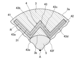
- FIG. 2 is an enlarged sectional view of the rotor.
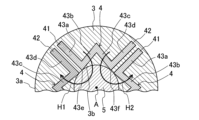
- FIG. 3 is a cross-sectional view showing the magnetic flux flow of permanent magnets in the rotor.
- FIG. 4 is a flowchart showing a rotor manufacturing method.
- FIG. 5 is a cross-sectional view showing a state when the permanent magnets are oriented.
- FIG. 6 is an enlarged cross-sectional view of a rotor according to another embodiment.
- FIG. 1 is a cross-sectional view of the motor 100.
- the motor 100 includes a rotor 1 that rotates around a predetermined rotation axis A, and a stator 6 that rotates the rotor 1 around the rotation axis A.
- a permanent magnet 4 is embedded in the rotor 1 . That is, the motor 100 is an IPM (Interior Permanent Magnet) motor.
- the motor 100 may further include a motor case 7 .
- a motor case 7 accommodates the rotor 1 and the stator 6 .
- the stator 6 is fixed with respect to the motor case 7 .
- the rotor 1 is rotatably supported by the motor case 7 .
- rotational axis direction A circumferential direction about the rotation axis A is called a “circumferential direction”.
- a radial direction about the rotation axis A is called a “radial direction”.
- the side facing the rotation axis A in the radial direction is referred to as “radial inner side”, and the side opposite to the rotation axis A is referred to as "radial outer side”.
- the stator 6 has a stator core 61 and windings 62 .
- Stator core 61 is a soft magnetic material.
- the stator core 61 is formed, for example, from a plurality of magnetic steel sheets laminated together.
- the stator core 61 is cylindrical.
- the stator core 61 is fixed to the motor case 7 .
- the stator core 61 is formed with a plurality of teeth 61a projecting inwardly of the stator core 61 .
- a plurality of teeth 61a are arranged in a line in the circumferential direction of stator core 61 at intervals.
- the winding 62 is wound around a plurality of teeth 61a.
- the stator 6 forms a rotating magnetic field that rotates the rotor 1 when current is supplied to the windings 62 .
- the rotor 1 includes a rotor body 2 that rotates around a rotation axis A and a plurality of permanent magnets 4 arranged in the rotor body 2 .
- At least part of the rotor body 2 is made of a soft magnetic material.
- the rotor body 2 has magnetic saliency and generates reluctance torque in the rotating magnetic field generated by the stator 6 .
- the rotor body 2 rotates around the rotation axis A. As shown in FIG.
- the rotor body 2 has a rotor core 3 having a rotation axis A and a shaft 5 .
- the rotor core 3 is a soft magnetic material.
- the rotor core 3 is formed, for example, from a plurality of magnetic steel sheets laminated together.
- the rotor core 3 is formed in a cylindrical shape concentric with the stator core 61 .
- the outer peripheral surface 3 a of the rotor core 3 forms the outer peripheral surface of the rotor body 2 .
- the cross-sectional shape of the rotor core 3 perpendicular to the rotation axis A is the same over the entire length of the rotor core 3 in the rotation axis direction.
- An air gap 10 is formed between the outer peripheral surface 3 a of the rotor core 3 and the inner peripheral surface of the stator core 61 .
- the shaft 5 is inserted coaxially with the rotation axis A inside the rotor core 20 .
- Shaft 5 is fixed to rotor core 20 .
- the shaft 5 is rotatably supported by the motor case 7 via bearings and the like.
- the rotor core 20 rotates around the rotation axis A together with the shaft 5 .
- the shaft 5 is a magnetic material (more specifically, a soft magnetic material).
- a plurality of permanent magnets 4 are arranged in the rotor core 3 in the circumferential direction to form magnetic poles that alternately differ in the circumferential direction.
- a plurality of permanent magnets 4 generate magnet torque in the rotating magnetic field formed by the stator 6 .
- the rotor 1 comprises four permanent magnets 4 .
- the plurality of permanent magnets 4 are arranged at regular intervals in the circumferential direction.
- a plurality of permanent magnets 4 are embedded in the rotor core 3 .
- the plurality of permanent magnets 4 are embedded in a portion of the rotor core 3 radially inside the outer peripheral surface 3a.
- the rotor core 3 is formed with a plurality (four in this example) of arrangement holes 31 in which the plurality of permanent magnets 4 are respectively embedded.
- Each of the plurality of arrangement holes 31 is a single through hole penetrating through the rotor core 3 in the rotation axis direction.
- the cross-sectional shape of the arrangement hole 31 orthogonal to the rotation axis A is the same as the cross-sectional shape of the permanent magnet 4 orthogonal to the rotation axis A. In other words, the permanent magnets 4 are embedded in the arrangement holes 31 with substantially no gaps.
- the permanent magnet 4 is a bond magnet.
- a bonded magnet is a permanent magnet made of a material obtained by mixing magnet powder and a binder for binding the magnet powder (hereinafter also referred to as "magnet material").
- the magnet powder is, for example, a powder of a neodymium magnet, a samarium-iron-nitrogen magnet, a samarium-cobalt magnet, a ferrite magnet, an alnico magnet, or a mixture of two or more of these powders.
- the binder is, for example, thermosetting resin such as epoxy resin, thermoplastic resin such as polyamide resin, or rubber. Bonded magnets can be molded like resin, and have higher dimensional accuracy and greater freedom in shape than sintered magnets.
- FIG. 2 is an enlarged sectional view of the rotor 1.
- FIG. The permanent magnet 4 is formed in a plate shape extending in the rotation axis direction. More specifically, the permanent magnet 4 extends over the entire length of the rotor core 3 in the rotation axis direction.
- the term "cross-sectional shape” means a cross-sectional shape perpendicular to the rotation axis A unless otherwise specified.
- the cross-sectional shape of the permanent magnet 4 is the same over the entire length of the permanent magnet 4 in the rotation axis direction.
- the cross-sectional shape of the permanent magnet 4 is linear. That is, the cross-sectional shape of the permanent magnet 4 has a shape extending along the predetermined reference line R. As shown in FIG.
- the permanent magnet 4 has two ends 41 and 42 and an intermediate portion 43 positioned between the two ends 41 and 42 in the direction in which the reference line R extends. Of course, the two end portions 41, 42 and the intermediate portion 43 are integrally formed.
- the permanent magnet 4 is curved or bent so that the intermediate portion 43 is closer to the rotation axis A than the two end portions 41 and 42 are. That is, the cross-sectional shape of the permanent magnet 4 is curved or bent so as to be concave radially inward. Specifically, the cross-sectional shape of the permanent magnet 4 is W-shaped.
- the intermediate portion 43 is located radially inside the two end portions 41 and 42 .
- the intermediate portion 43 has four linear portions 43a, 43b, 43c, 43d and two closest portions 43e, 43f.
- first linear portion 43a When distinguishing between the four linear portions 43a, 43b, 43c, and 43d, they are respectively "first linear portion 43a,” “second linear portion 43b,” “third linear portion 43c,” and " It is referred to as a "fourth linear portion 43d".
- first closest portion 43e and 43f When distinguishing between the two closest portions 43e and 43f, they are referred to as "first closest portion 43e" and "second closest portion 43f", respectively.
- Each of the four linear portions 43a, 43b, 43c, 43d is a linear member extending along the reference line R. More specifically, the four linear portions 43a, 43b, 43c, 43d extend linearly. In this example, the four linear portions 43a, 43b, 43c, and 43d have the same thickness (that is, the length in the direction orthogonal to the reference line R in the cross section orthogonal to the rotation axis A).
- the first linear portion 43a is connected to one end 41 of the two ends 41 and 42 and extends from the end 41 so as to approach the rotation axis A.
- the second linear portion 43b is connected to the end of the first linear portion 43a and extends from the first linear portion 43a so as to be separated from the rotation axis A.
- the third linear portion 43c is connected to the end of the second linear portion 43b and extends to approach the rotation axis A.
- the fourth linear portion 43 d is connected to the end of the third linear portion 43 c , extends from the third linear portion 43 c so as to be separated from the rotation axis A, and is connected to the other end 42 .
- the first linear portion 43a and the second linear portion 43b are connected so as to form a V shape that opens radially outward.
- the second linear portion 43b and the third linear portion 43c are connected to form a V-shape that opens radially inward.
- the third linear portion 43c and the fourth linear portion 43d are connected to form a V-shape that opens radially outward.
- the two ends 41, 42 and the four linear portions 43a, 43b, 43c, 43d form a W shape.
- the permanent magnet 4 is curved or bent so that the intermediate portion 43 is closer to the rotation axis A than the two end portions 41 and 42, thereby increasing the surface area and thus the volume of the permanent magnet 4. .
- An increase in the surface area of the permanent magnet 4 increases the magnet torque, and thus the torque of the motor 100 .
- the two closest parts 43e and 43f are the parts of the intermediate part 43 that are closest to the rotation axis A.
- Each of the two closest portions 43e and 43f coincides with the inner peripheral surface 3b of the rotor core 3.
- the two closest portions 43e and 43f are located on the inner peripheral surface 3b of the rotor core 3, respectively.
- the two closest portions 43e and 43f are close to the inner peripheral surface 3b of the rotor core 3.
- the two closest portions 43e and 43f are exposed from the inner peripheral surface 3b of the rotor core 3.
- the two closest parts 43e and 43f are two parts that curve or bend in the same direction in the W shape. More specifically, the first closest portion 43e is a connecting portion between the first linear portion 43a and the second linear portion 43b. That is, the first closest portion 43e is a V-shaped corner formed by the first linear portion 43a and the second linear portion 43b.
- the second closest portion 43f is a connection portion between the third linear portion 43c and the fourth linear portion 43d. That is, the second closest portion 43f is a V-shaped corner formed by the third linear portion 43c and the fourth linear portion 43d.
- the rotor core 3 Since the closest portions 43e and 43f are aligned with the inner peripheral surface 3b of the rotor core 3, the rotor core 3 is not interposed between the closest portions 43e and 43f and the inner peripheral surface 3b of the rotor core 3. . In other words, the rotor core 3 does not exist between the closest portions 43 e and 43 f and the shaft 5 . Then, in the rotor 1, the so-called q-axis inductance is lowered. Lowering the q-axis inductance improves the power factor.
- FIG. 3 is a cross-sectional view showing the magnetic flux flow of the permanent magnets 4 in the rotor 1.
- the closest approach portions 43e and 43f of the permanent magnets 4 are aligned with the inner peripheral surface 3b of the rotor core 3, and the shaft 5 is a magnetic material, as described above. Therefore, in the permanent magnet 4 , the magnetic flux H1 from the second linear portion 43 b reliably flows through the shaft 5 to the third linear portion 43 c of another permanent magnet 4 . Also, in the permanent magnet 4 , the magnetic flux H2 from the third linear portion 43 c reliably flows through the shaft 5 to the second linear portion 43 b of another permanent magnet 4 .
- the magnetic fluxes H1 and H2 from the second linear portion 43b and the third linear portion 43c will flow to the closest portions 43e and 43f. and the shaft 5, this is prevented in this example.
- the shaft 5 is made of a magnetic material
- the magnetic fluxes H1 and H2 from the second linear portion 43b and the third linear portion 43c pass through the shaft 5 and separate from each other, compared to the case where the shaft 5 is not made of a magnetic material. It becomes easier to flow to the second linear portion 43 b and the third linear portion 43 c of the permanent magnet 4 . Thereby, the magnetic flux density of the permanent magnet 4 is increased. Therefore, magnet torque increases.
- FIG. 4 is a flow chart showing a method for manufacturing the rotor 1.
- FIG. 5 is a cross-sectional view showing the orientation of the permanent magnets 4.
- the permanent magnet 4 is referred to as a bond magnet for explanation.
- step S1 a rotor core 3 having a plurality of placement holes 31 for arranging bond magnets is prepared.
- step S2 the bonded magnet before magnetization is injection molded.
- step S2 orientation of the bonded magnets is also performed when the bonded magnets are injection molded.
- the bond magnet material that is, the magnet material
- the bond magnet before magnetization is injection molded.
- a plurality of orientation magnets hereinafter referred to as "outer magnets 91, 92, 93, 94" and “inner magnets 96, 97, 98, 99" are positioned to orient the bonded magnets prior to magnetization.
- the rotor core 3 prepared in step S1 is installed in a predetermined mold (not shown).
- the mold is formed with, for example, sprues and runners, which are flow paths for the magnet material.
- a bond magnet before magnetization is injection molded by injecting a magnet material into each of the plurality of arrangement holes 31 via a sprue or the like.
- the same number of outer magnets 91, 92, 93, and 94 as the placement holes 31 are arranged outside the rotor core 3 installed in the mold.
- the same number of inner magnets 96, 97, 98, 99 as the placement holes 31 are arranged inside.
- Each of the four outer magnets 91 , 92 , 93 , 94 is positioned corresponding to each of the four placement holes 31 .
- Each of the four inner magnets 96 , 97 , 98 , 99 is also positioned corresponding to each of the four placement holes 31 .
- the outer magnets 91, 92, 93, 94 and the inner magnets 96, 97, 98, 99 face each other with the corresponding arrangement holes 31 interposed therebetween.
- the outer magnets 91, 92, 93, 94 and the inner magnets 96, 97, 98, 99 are oriented before being magnetized.
- the orientation state of the bond magnet will be described with reference to FIG.
- the orientation state of one of the four bond magnets that is, the upper bond magnet in FIG. 5
- the orientation state of the upper bond magnet is illustrated, and illustration of the other three bond magnets is omitted.
- the two outer magnets 91 and 94 orient the first linear portion 43a of the bond magnet and the fourth linear portion 43d of another adjacent bond magnet. That is, the magnetic flux H3 from the outer magnet 94 passes through the fourth linear portion 43d and the first linear portion 43a in this order, and flows to the outer magnet 91.
- the two outer magnets 91 and 92 orient the fourth linear portion 43d of the bond magnet and the first linear portion 43a of another adjacent bond magnet. That is, the magnetic flux H4 from the outer magnet 92 passes through the first linear portion 43a and the fourth linear portion 43d in this order, and flows to the outer magnet 91.
- the outer magnet 91 and the inner magnet 96 orient the second linear portion 43b and the third linear portion 43c of the bond magnet.
- the magnetic flux H5 from the inner magnet 96 flows to the outer magnet 91 through the second linear portion 43b.
- Another magnetic flux H6 from the inner magnet 96 flows to the outer magnet 91 through the third linear portion 43c.
- the inner magnets 96, 97, 98, 99 are arranged to orient the second linear portion 43b and the third linear portion 43c, which are difficult to orient only with the outer magnets 91, 92, 93, 94. be.
- the inner magnet 96 since the first closest portion 43e coincides with the inner peripheral surface 3b of the rotor core 3, that is, since the rotor core 3 does not exist between the first closest portion 43e and the inner peripheral surface 3b, the inner magnet The magnetic flux H5 from 96 reliably passes through the second linear portion 43b without short-circuiting.
- the second closest portion 43f coincides with the inner peripheral surface 3b of the rotor core 3, that is, since the rotor core 3 does not exist between the second closest portion 43f and the inner peripheral surface 3b
- the inner magnet 96 The magnetic flux H6 from the terminal reliably passes through the third linear portion 43c without being short-circuited. Therefore, the second linear portion 43b and the third linear portion 43c are appropriately oriented. Therefore, the overall orientation ratio of the bonded magnet is improved.
- step S3 magnetization is performed by a magnetizer. Specifically, after injection-molding and orienting the bond magnets before magnetization in step S2, a plurality of magnetizing magnets corresponding to the plurality of arrangement holes 31 are arranged outside and inside the rotor core 3. to magnetize the bond magnet before magnetization. That is, the unmagnetized bond magnets arranged in the plurality of arrangement holes 31 are magnetized.
- outer magnets 91, 92, 93, 94 and inner magnets 96, 97, 98, 99 as shown in FIG. 5 are arranged as magnetizing magnets.
- the flow of the magnetic fluxes H3 to H6 causes the first linear portion 43a, the second linear portion 43b, the third linear portion 43c, and the fourth linear portion 43d to adhere to each other in the bond magnet. magnetized.
- the magnetic fluxes H5 and H6 from the inner magnet 96 pass through the second linear portion 43b and the third linear portion 43c without being short-circuited. Appropriate magnetization is performed on the shaped portion 43c. Therefore, the magnetization rate of the bond magnet as a whole is improved.
- step S4 the shaft 5 is attached to the rotor core 3. With the above, the manufacture of the rotor 1 is completed.
- the rotor 1 includes a rotor core 3 having a rotation axis A, and a plurality of permanent magnets 4 arranged in the rotor core 3 in the circumferential direction around the rotation axis A and forming magnetic poles alternately different in the circumferential direction. It has A cross-sectional shape of the permanent magnet 4 orthogonal to the rotation axis A is a shape extending along a predetermined reference line R. As shown in FIG. The permanent magnet 4 is curved or bent such that the intermediate portion 43 positioned between the two ends 41 and 42 in the direction of the reference line R is closer to the rotation axis A than the two ends 41 and 42 . ing. The closest portions 43 e and 43 f of the intermediate portion 43 that are closest to the rotation axis A coincide with the inner peripheral surface 3 b of the rotor core 3 .
- the motor 100 also includes a cylindrical stator 6 and a rotor 1 arranged inside the stator 6 .
- the method of manufacturing the rotor 1 is a method of manufacturing the rotor 1 in which the permanent magnets 4 are bonded magnets.
- This manufacturing method consists of preparing the rotor core 3 in which a plurality of placement holes 31 for arranging the bond magnets are formed, and injecting a bond magnet material into each of the plurality of placement holes 31 of the rotor core 3 to magnetize the magnets.
- a plurality of orienting magnets that is, positioning the outer magnets 91, 92, 93, 94 and the inner magnets 96, 97, 98, 99 to orient the bonded magnets prior to magnetization.
- Another manufacturing method of the rotor 1 is a manufacturing method of the rotor 1 in which the permanent magnets 4 are bond magnets.
- This manufacturing method consists of preparing the rotor core 3 in which a plurality of placement holes 31 for arranging the bond magnets are formed, and injecting a bond magnet material into each of the plurality of placement holes 31 of the rotor core 3 to magnetize the magnets. After injection molding the previous bond magnet and injection molding the bond magnet before magnetization, a plurality of magnetizing magnets (i.e., positioning the outer magnets 91, 92, 93, 94 and the inner magnets 96, 97, 98, 99) to magnetize the bond magnets before magnetization.
- the permanent magnet 4 is curved or bent so that the intermediate portion 43 is closer to the rotation axis A than the two end portions 41 and 42, so that the surface area and volume of the permanent magnet 4 is increased.
- the magnet torque, and consequently the torque of the motor 100 can be increased.
- the rotor core 3 is not interposed between the closest portions 43e and 43f and the inner peripheral surface 3b. In other words, the rotor core 3 does not exist between the closest portions 43 e and 43 f and the shaft 5 .
- the so-called q-axis inductance is lowered, so the power factor can be improved.
- the arrangement area of the permanent magnets 4 can be increased in the radial direction of the rotor core 3, and the surface area of the permanent magnets 4 can be further increased. can be done. As described above, the torque of the motor 100 can be increased and the power factor of the motor 100 can be improved.
- the cross-sectional shape of the permanent magnet 4 perpendicular to the rotation axis A is W-shaped.
- the closest portions 43e and 43f are two portions that curve or bend in the same direction in the W shape.
- the surface area of the permanent magnet 4 can be increased. Therefore, the torque of the motor 100 can be further increased.
- the rotor 1 further includes a magnetic shaft 5 inserted coaxially with the rotation axis A inside the rotor core 3 .
- the shaft 5 is a magnetic material
- the magnetic fluxes H1 and H2 from the second linear portion 43b and the third linear portion 43c pass through the shaft 5 as compared with the case where the shaft 5 is not a magnetic material.
- the magnetic flux density of the permanent magnet 4 is increased. Therefore, magnet torque increases.
- the permanent magnet 4 is a bond magnet.
- the cross-sectional shape of the permanent magnet may be U-shaped as shown in FIG.
- FIG. 6 is an enlarged cross-sectional view of the rotor 1 according to another embodiment.
- the permanent magnets 8 of this example are also embedded in a plurality of arrangement holes 32 formed in the rotor core 3.
- the cross-sectional shape of the permanent magnet 8 in this example is linear. That is, the cross-sectional shape of the permanent magnet 8 has a shape extending along a predetermined reference line R. As shown in FIG.
- the permanent magnet 8 has two end portions 81 and 82 and an intermediate portion 83 located between the two end portions 81 and 82 in the direction in which the reference line R extends.
- the permanent magnet 8 is also curved or bent so that the intermediate portion 83 is closer to the rotation axis A than the two end portions 81 and 82 are. That is, the cross-sectional shape of the permanent magnet 8 is curved or bent so as to be concave radially inward.
- the two ends 81 and 82 are positioned radially outermost in the permanent magnet 8 as a whole.
- the intermediate portion 83 is located radially inside the two end portions 81 and 82 .
- the intermediate portion 83 has two linear portions 83a and 83b and one closest portion 83c. When distinguishing between the two linear portions 83a and 83b, they are referred to as “first linear portion 83a” and “second linear portion 83b", respectively.
- Each of the two linear portions 83a and 83b is a linear member extending along the reference line R. More specifically, the two linear portions 83a and 83b extend curvedly. In this example, the two linear portions 83a and 83b have the same thickness (that is, the length in the direction orthogonal to the reference line R in the cross section orthogonal to the rotation axis A).
- the first linear portion 83a is connected to one end portion 81 and extends from the end portion 81 so as to approach the rotation axis A.
- the second linear portion 83 b is connected to the end of the first linear portion 83 a , extends from the first linear portion 83 a so as to be separated from the rotation axis A, and is connected to the other end 82 .
- the closest portion 83c is the portion of the intermediate portion 83 that is closest to the rotation axis A.
- the closest portion 83 c is aligned with the inner peripheral surface 3 b of the rotor core 3 .
- the closest portion 83 c is located on the inner peripheral surface 3 b of the rotor core 3 .
- the closest portion 83 c is close to the inner peripheral surface 3 b of the rotor core 3 . That is, the closest portion 83c is exposed from the inner peripheral surface 3b of the rotor core 3.
- the closest portion 83c is a connecting portion between the first linear portion 83a and the second linear portion 83b. That is, the closest portion 83c is the portion that is most recessed radially inward in the U shape.
- the permanent magnet 8 is curved or bent so that the middle portion 83 is closer to the rotation axis A than the two end portions 81 and 82, thereby increasing the surface area and thus the volume of the permanent magnet 8.
- Permanent magnet As a result, the magnet torque and the torque of the motor 100 are increased. Since the closest portion 83c coincides with the inner peripheral surface 3b of the rotor core 3, the rotor core 3 is not interposed between the closest portion 83c and the inner peripheral surface 3b, so that the so-called q-axis inductance is reduced. . Therefore, the power factor is improved.
- the number of permanent magnets 4 is not limited to the number described above.
- the number of closest approach parts in the permanent magnet 4 is two, but is not limited to this, and may be one, for example.
- the cross-sectional shape of the permanent magnet 4 is not limited to the above-described shape, and may be, for example, a V-shape, or a wave-like shape having three or more curved or bent portions in the same direction. good.
- the permanent magnet 4 may be an anisotropic bonded magnet or an isotropic bonded magnet. Also, the permanent magnet 4 may be a sintered magnet.
- the shaft 5 does not have to be a soft magnetic material. Moreover, the shaft 5 may be formed integrally with the rotor core 3 .
Landscapes
- Engineering & Computer Science (AREA)
- Power Engineering (AREA)
- Manufacturing & Machinery (AREA)
- Permanent Field Magnets Of Synchronous Machinery (AREA)
Priority Applications (5)
| Application Number | Priority Date | Filing Date | Title |
|---|---|---|---|
| PCT/JP2021/031025 WO2023026371A1 (ja) | 2021-08-24 | 2021-08-24 | ロータ、モータ、及びロータの製造方法 |
| JP2023543709A JP7654090B2 (ja) | 2021-08-24 | 2022-06-13 | ロータ、モータ、及びロータの製造方法 |
| PCT/JP2022/023672 WO2023026640A1 (ja) | 2021-08-24 | 2022-06-13 | ロータ、モータ、及びロータの製造方法 |
| CN202280057328.XA CN117837061A (zh) | 2021-08-24 | 2022-06-13 | 转子、马达以及转子的制造方法 |
| US18/685,325 US20250055333A1 (en) | 2021-08-24 | 2022-06-13 | Rotor, motor, and rotor manufacturing method |
Applications Claiming Priority (1)
| Application Number | Priority Date | Filing Date | Title |
|---|---|---|---|
| PCT/JP2021/031025 WO2023026371A1 (ja) | 2021-08-24 | 2021-08-24 | ロータ、モータ、及びロータの製造方法 |
Publications (1)
| Publication Number | Publication Date |
|---|---|
| WO2023026371A1 true WO2023026371A1 (ja) | 2023-03-02 |
Family
ID=85321748
Family Applications (2)
| Application Number | Title | Priority Date | Filing Date |
|---|---|---|---|
| PCT/JP2021/031025 Ceased WO2023026371A1 (ja) | 2021-08-24 | 2021-08-24 | ロータ、モータ、及びロータの製造方法 |
| PCT/JP2022/023672 Ceased WO2023026640A1 (ja) | 2021-08-24 | 2022-06-13 | ロータ、モータ、及びロータの製造方法 |
Family Applications After (1)
| Application Number | Title | Priority Date | Filing Date |
|---|---|---|---|
| PCT/JP2022/023672 Ceased WO2023026640A1 (ja) | 2021-08-24 | 2022-06-13 | ロータ、モータ、及びロータの製造方法 |
Country Status (4)
| Country | Link |
|---|---|
| US (1) | US20250055333A1 (https=) |
| JP (1) | JP7654090B2 (https=) |
| CN (1) | CN117837061A (https=) |
| WO (2) | WO2023026371A1 (https=) |
Citations (6)
| Publication number | Priority date | Publication date | Assignee | Title |
|---|---|---|---|---|
| JPH08256441A (ja) * | 1995-01-20 | 1996-10-01 | Hitachi Metals Ltd | 永久磁石式ロータ |
| JP2000197320A (ja) * | 1998-10-23 | 2000-07-14 | Mitsubishi Electric Corp | 永久磁石埋込み形モ―タおよびその製造方法 |
| JP2004289940A (ja) * | 2003-03-24 | 2004-10-14 | Sumitomo Metal Mining Co Ltd | 永久磁石式モータ |
| JP2014103741A (ja) * | 2012-11-19 | 2014-06-05 | Jtekt Corp | 磁石埋込型ロータ |
| WO2016135813A1 (ja) * | 2015-02-23 | 2016-09-01 | 成田 憲治 | 同期電動機 |
| JP2016197934A (ja) * | 2015-04-02 | 2016-11-24 | 株式会社東芝 | 永久磁石回転電機 |
Family Cites Families (6)
| Publication number | Priority date | Publication date | Assignee | Title |
|---|---|---|---|---|
| JPS63202006A (ja) * | 1987-02-18 | 1988-08-22 | Fanuc Ltd | 着磁装置 |
| JPH04145861A (ja) * | 1990-10-04 | 1992-05-19 | Fanuc Ltd | ラジアルタイプのロータとそれに使用する着磁器 |
| JP5301868B2 (ja) * | 2007-04-27 | 2013-09-25 | アスモ株式会社 | 埋込磁石型モータ |
| US9130422B2 (en) * | 2013-03-08 | 2015-09-08 | GM Global Technology Operations LLC | Interior permanent magnet machine having a mixed rare earth magnet and ferrite magnet rotor |
| JP6237412B2 (ja) * | 2014-03-31 | 2017-11-29 | ダイキン工業株式会社 | 磁石埋込型回転電気機械のロータ構造 |
| JP2016152653A (ja) | 2015-02-16 | 2016-08-22 | 株式会社ジェイテクト | 磁石埋込型ロータの製造装置及び磁石埋込型ロータの製造方法 |
-
2021
- 2021-08-24 WO PCT/JP2021/031025 patent/WO2023026371A1/ja not_active Ceased
-
2022
- 2022-06-13 CN CN202280057328.XA patent/CN117837061A/zh active Pending
- 2022-06-13 JP JP2023543709A patent/JP7654090B2/ja active Active
- 2022-06-13 US US18/685,325 patent/US20250055333A1/en active Pending
- 2022-06-13 WO PCT/JP2022/023672 patent/WO2023026640A1/ja not_active Ceased
Patent Citations (6)
| Publication number | Priority date | Publication date | Assignee | Title |
|---|---|---|---|---|
| JPH08256441A (ja) * | 1995-01-20 | 1996-10-01 | Hitachi Metals Ltd | 永久磁石式ロータ |
| JP2000197320A (ja) * | 1998-10-23 | 2000-07-14 | Mitsubishi Electric Corp | 永久磁石埋込み形モ―タおよびその製造方法 |
| JP2004289940A (ja) * | 2003-03-24 | 2004-10-14 | Sumitomo Metal Mining Co Ltd | 永久磁石式モータ |
| JP2014103741A (ja) * | 2012-11-19 | 2014-06-05 | Jtekt Corp | 磁石埋込型ロータ |
| WO2016135813A1 (ja) * | 2015-02-23 | 2016-09-01 | 成田 憲治 | 同期電動機 |
| JP2016197934A (ja) * | 2015-04-02 | 2016-11-24 | 株式会社東芝 | 永久磁石回転電機 |
Also Published As
| Publication number | Publication date |
|---|---|
| WO2023026640A1 (ja) | 2023-03-02 |
| US20250055333A1 (en) | 2025-02-13 |
| JPWO2023026640A1 (https=) | 2023-03-02 |
| CN117837061A (zh) | 2024-04-05 |
| JP7654090B2 (ja) | 2025-03-31 |
Similar Documents
| Publication | Publication Date | Title |
|---|---|---|
| JP4096843B2 (ja) | モータ及びその製造方法 | |
| CN107852046B (zh) | 具有附加的自有磁化部的磁阻转子 | |
| US10566859B2 (en) | Rotor | |
| WO2005101614A1 (ja) | 回転子及びその製造方法 | |
| US20170070111A1 (en) | Interior Permanent Magnet Rotor and Method for Manufacturing the Same | |
| CN105186732A (zh) | 通量引导得到改善的用于电的机器的转子或定子 | |
| JP6121914B2 (ja) | 同期電動機 | |
| JP7723102B2 (ja) | インナロータ及びモータ | |
| JP7654795B2 (ja) | ロータおよびモータ | |
| CN107394917B (zh) | 定向磁化装置以及磁铁埋入型转子 | |
| WO2023026371A1 (ja) | ロータ、モータ、及びロータの製造方法 | |
| US20250070604A1 (en) | Rotor and motor | |
| JP7774454B2 (ja) | 永久磁石型回転機 | |
| JP7679475B2 (ja) | ロータ及びモータ | |
| JP4013916B2 (ja) | 4磁極モータ用異方性ボンド磁石の配向処理装置 | |
| JP2019146463A (ja) | 回転電機のロータ、回転電機、及び回転電機のロータ製造方法 | |
| WO2024142392A1 (ja) | ロータ及びロータの製造方法 | |
| WO2017203570A1 (ja) | Ipmモータのロータ、ipmモータ、及びipmモータのロータの製造方法 | |
| JP2017169317A (ja) | ロータ | |
| CN104067483B (zh) | 同步电动机 | |
| CN116526775A (zh) | 用于制造转子的方法 | |
| JPH11289739A (ja) | モータ |
Legal Events
| Date | Code | Title | Description |
|---|---|---|---|
| 121 | Ep: the epo has been informed by wipo that ep was designated in this application |
Ref document number: 21954986 Country of ref document: EP Kind code of ref document: A1 |
|
| NENP | Non-entry into the national phase |
Ref country code: DE |
|
| 122 | Ep: pct application non-entry in european phase |
Ref document number: 21954986 Country of ref document: EP Kind code of ref document: A1 |
|
| NENP | Non-entry into the national phase |
Ref country code: JP |