WO2023022065A1 - 容器 - Google Patents
容器 Download PDFInfo
- Publication number
- WO2023022065A1 WO2023022065A1 PCT/JP2022/030391 JP2022030391W WO2023022065A1 WO 2023022065 A1 WO2023022065 A1 WO 2023022065A1 JP 2022030391 W JP2022030391 W JP 2022030391W WO 2023022065 A1 WO2023022065 A1 WO 2023022065A1
- Authority
- WO
- WIPO (PCT)
- Prior art keywords
- lid
- metal film
- rfid
- electrode
- rfid module
- Prior art date
- Legal status (The legal status is an assumption and is not a legal conclusion. Google has not performed a legal analysis and makes no representation as to the accuracy of the status listed.)
- Ceased
Links
Images
















Classifications
-
- B—PERFORMING OPERATIONS; TRANSPORTING
- B65—CONVEYING; PACKING; STORING; HANDLING THIN OR FILAMENTARY MATERIAL
- B65D—CONTAINERS FOR STORAGE OR TRANSPORT OF ARTICLES OR MATERIALS, e.g. BAGS, BARRELS, BOTTLES, BOXES, CANS, CARTONS, CRATES, DRUMS, JARS, TANKS, HOPPERS, FORWARDING CONTAINERS; ACCESSORIES, CLOSURES, OR FITTINGS THEREFOR; PACKAGING ELEMENTS; PACKAGES
- B65D77/00—Packages formed by enclosing articles or materials in preformed containers, e.g. boxes, cartons, sacks or bags
- B65D77/10—Container closures formed after filling
- B65D77/20—Container closures formed after filling by applying separate lids or covers, i.e. flexible membrane or foil-like covers
-
- G—PHYSICS
- G06—COMPUTING OR CALCULATING; COUNTING
- G06K—GRAPHICAL DATA READING; PRESENTATION OF DATA; RECORD CARRIERS; HANDLING RECORD CARRIERS
- G06K19/00—Record carriers for use with machines and with at least a part designed to carry digital markings
- G06K19/06—Record carriers for use with machines and with at least a part designed to carry digital markings characterised by the kind of the digital marking, e.g. shape, nature, code
- G06K19/067—Record carriers with conductive marks, printed circuits or semiconductor circuit elements, e.g. credit or identity cards also with resonating or responding marks without active components
- G06K19/07—Record carriers with conductive marks, printed circuits or semiconductor circuit elements, e.g. credit or identity cards also with resonating or responding marks without active components with integrated circuit chips
- G06K19/077—Constructional details, e.g. mounting of circuits in the carrier
-
- H—ELECTRICITY
- H01—ELECTRIC ELEMENTS
- H01Q—ANTENNAS, i.e. RADIO AERIALS
- H01Q1/00—Details of, or arrangements associated with, antennas
- H01Q1/12—Supports; Mounting means
- H01Q1/22—Supports; Mounting means by structural association with other equipment or articles
- H01Q1/24—Supports; Mounting means by structural association with other equipment or articles with receiving set
Definitions
- the present disclosure relates to a container with RFID function.
- the present disclosure relates to a container with an RFID function that utilizes RFID (Radio Frequency Identification) technology for non-contact data communication using an induced electromagnetic field or radio waves.
- RFID Radio Frequency Identification
- RFID tags which are wireless communication devices
- an RFID tag together with an RFIC (Radio-Frequency Integrated Circuit) element, a metal material such as an antenna pattern is formed on an insulating substrate such as paper or resin.
- RFIC Radio-Frequency Integrated Circuit
- Patent Document 1 proposes a configuration in which an RFID tag is provided that is compatible with metal formed on a part of the container so as not to impair the design.
- the present disclosure provides a container with an RFID function that can reduce the possibility that an RFID module will be mixed into the contents while suppressing the deterioration of the design in a container in which a lid having a metal film is attached to the main body that houses the contents. offer.
- An RFID function-equipped container includes an electrically insulating main body having an accommodation space for contents, a lid including a metal film and attached to the main body so as to cover an opening of the accommodation space, and the accommodation an RFID module having first and second electrodes attached to the body or the lid so as to be outside the opening of the space and coupled to the metal membrane.
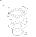
- FIG. 1 is an exploded perspective view of a configuration example of a container with an RFID function according to Embodiment 1.
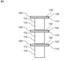
- FIG. Bottom view of lid of container with RFID function in FIG. Schematic diagram showing a state in which the RFID function-equipped containers 100 are stacked (a) is a plan view of a configuration example of the RFID module of the container with RFID function in FIG. 1, and (b) is a bottom view of a configuration example of the RFID module.
- Cross-sectional view of line YY in FIG. 4(a) A circuit diagram of an example of the circuit configuration of the RFID function-equipped container in FIG.
- FIG. 31 is a perspective view showing a state in which the lid is peeled off from the main body in the RFID function-equipped container of FIG.
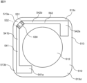
- the bottom view of the lid peeled off from the main body in Modification 1 of Embodiment 6 The bottom view of the configuration example of the lid of the RFID function-equipped container according to Modification 2 of Embodiment 6.
- FIG. 38 is a perspective view showing a state in which the lid is peeled off from the main body in the RFID function-equipped container of FIG.
- the bottom view of the lid peeled off from the main body in the container with RFID function of FIG. Bottom view of a configuration example of a lid in a container with an RFID function according to a modified example of the seventh embodiment
- FIG. 1 is an exploded perspective view of a configuration example of a container 100 with RFID function according to Embodiment 1.
- the RFID function-equipped container 100 of FIG. 1 is used, for example, in a system for identifying and managing products by wireless communication.
- the RFID function-equipped container 100 of FIG. 1 is traded as a product while containing the content N100.
- the content N100 is, for example, an article for commercial transactions.
- Contents N100 can be liquid, solid, sol, gel, or combinations thereof. Examples of contents N100 include food, medicines, medical or orthodontic appliances, and the like.
- Foods include foods that can be provided in a container, such as yogurt, pudding, and instant foods. Medical or corrective devices include contact lenses.
- the RFID function-equipped container 100 in FIG. 1 The RFID function-equipped container 100 in FIG. 1
- the main body 110 of FIG. 1 has an accommodation space 111 for the contents N100.
- the main body 110 has electrical insulation.
- the main body 110 is made of dielectric material such as paper, resin material, or glass, for example.
- the resin material includes expanded polystyrene, for example.
- the main body 110 of FIG. 1 has a bottomed tubular portion 112 and a flange portion 113 .
- the tubular portion 112 defines the accommodation space 111 .
- the tubular portion 112 in FIG. 1 is cylindrical.
- the flange portion 113 protrudes outward from the opening edge of the housing space 111 .
- the outer shape of the flange portion 113 in FIG. 1 is square.
- the lid 120 in FIG. 1 is attached to the main body 110 so as to cover the opening of the accommodation space 111 .
- lid 120 is releasably attached to main body 110 .
- the lid 120 is peeled off from the main body 110 when the content N100 is taken out from the housing space 111 of the main body 110 .
- Lid 120 is generally flexible.
- the lid 120 is attached to the periphery of the opening of the housing space 111 of the main body 110 with an adhesive.
- the lid 120 is adhesively attached to the flange portion 113 of the body 110 .
- the adhesive is applied to a region of lid 120 facing flange portion 113 .
- the lid 120 includes a base material 121 and a metal film 122.
- the base material 121 covers the opening of the accommodation space 111 .
- the base material 121 entirely covers the opening of the accommodation space 111 and the flange portion 113 .
- the outer shape of the base material 121 is square.
- Substrate 121 is formed from a dielectric material such as paper or plastic, for example.
- the metal film 122 covers the opening of the accommodation space 111 of the main body 110 .
- the metal film 122 entirely covers the opening of the housing space 111 and the flange portion 113 .
- the metal film 122 is on the surface of the base material 121 on the main body 110 side.
- the metal film 122 can act to prevent changes in the contents caused by external factors.
- the metal film 122 protects the content N100 by covering the opening of the accommodation space 111.
- Materials for the metal film 122 include aluminum and alloys containing aluminum.
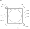
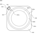
- FIG. 2 is a bottom view of the lid 120.
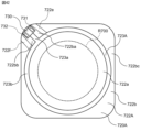
- the metal film 122 is divided into multiple parts. More specifically, the metal film 122 is divided into first to fourth side portions 122 a to 122 d corresponding to the four sides of the metal film 122 and a center portion 122 e covering the opening of the accommodation space 111 .
- the central portion 122e includes a predetermined region R100 covering the opening of the accommodation space 111 in the metal film 122.
- the first to fourth side portions 122a to 122d and the central portion 122e are electrically isolated from each other.
- the first through fourth sides 122 a - 122 d can be used as antenna patterns for the RFID module 130 .
- Adjacent two of the first to fourth side portions 122 a to 122 d of the metal film 122 can be used as antenna patterns for the RFID module 130 . That is, the RFID module 130 may be set at any of the four corners of the lid 120 . Therefore, the degree of freedom in arranging the RFID module 130 on the lid 120 is improved.
- the first and second sides 122a and 122b form first and second antenna patterns that are electrically independent of each other.
- the first side portion 122a may be referred to as the first antenna pattern 122a
- the second side portion 122b may be referred to as the second antenna pattern 122b.
- the metal film 122 is divided by slits 123 formed in the metal film 122 into first to fourth side portions 122 a to 122 d and a central portion 122 e covering the opening of the accommodation space 111 . Therefore, the shapes of the first and second antenna patterns 122 a and 122 b are defined by the slits 123 formed in the metal film 122 .
- the slit 123 is arranged in the metal film 122 so as to avoid the predetermined region R100 covering the opening of the accommodation space 111 of the main body 110 . Accordingly, the antenna patterns 122a and 122b can be provided without affecting the function of the metal film 122 to protect the content N100.
- the frame portion 123a has a rectangular frame shape surrounding the predetermined region R100.
- the four sides of the frame portion 123a are parallel to the four sides of the metal film 122, respectively.
- Each of the first to fourth extensions 123b-1 to 123b-4 extends from the corner of the frame 123a to the corner of the metal film 122 that is the closest.
- the first and fourth extensions 123b-1 and 123b-4 are positioned on the same diagonal line of the lid 120.
- the second and third extensions 123b-2 and 123b-3 are positioned on the same diagonal line of the lid 120. As shown in FIG.
- the frame portion 123a is a first portion that is formed to surround the opening of the housing space 111 and electrically separates the first and second antenna patterns 122a and 122b from the predetermined region R100.
- the first extension part 123b-1 is a second part formed at the edge of the opening of the accommodation space 111 and electrically separating the first and second antenna patterns 122a and 122b. Note that the slit 123 penetrates the metal film 122 but does not penetrate the base material 121 .
- the RFID module 130 is a wireless communication device configured to wirelessly communicate (transmit and receive) using high-frequency signals having a communication frequency (carrier frequency).
- the RFID module 130 is configured, for example, to perform wireless communication using a high-frequency signal having a frequency for communication in the UHF band.
- the UHF band is a frequency band from 860 MHz to 960 MHz.
- the RFID module 130 is outside the predetermined region R100 on the lid 120 and is coupled to the metal film 122. As shown in FIG. That is, the RFID module 130 is outside the opening of the housing space 111 in the lid 120 and coupled to the metal film 122 . Being outside the opening of the accommodation space 111 means not overlapping the accommodation space 111 on a plane orthogonal to the depth direction of the accommodation space 111 .
- the RFID module 130 is on the body 110 side of the lid 120 (that is, on the back side of the lid 120). In particular, the RFID module 130 is located at a portion of the lid 120 facing the flange portion 113 of the main body 110 .
- FIG. 3 is a schematic diagram showing a state in which the RFID function-equipped containers 100 are stacked.
- the RFID module 130 is located at a portion of the lid 120 facing the flange portion 113 of the main body 110 . Therefore, the RFID module 130 is less affected by another container 100 with RFID function, particularly by the contents N100, than when the RFID module 130 is located in the lid 120 overlapping the housing space 111 of the main body 110. Hard to accept. Therefore, when the RFID function-equipped container 100 of the present embodiment is stacked, the tubular portion 112 of the main body 110 overlaps with the RFID function-equipped container 100 , reducing the possibility of impairing the function of the RFID module 130 .
- the RFID module 130 is coupled to the metal film 122 in the lid 120 so as to straddle the first extension 123b-1 of the slit 123. More specifically, the RFID module 130 has first and second electrodes 131, 132 such that the first and second electrodes 131, 132 are respectively coupled to the first and second antenna patterns 122a, 122b. , on lid 120 . In this embodiment, the first and second electrodes 131, 132 are capacitively coupled to the first and second antenna patterns 122a, 122b, respectively.
- the lid 120 has a protective film 124 (see FIG. 6). 1 and 2, the protective film 124 is omitted for simplification of the drawings.
- a protective film 124 covers the metal film 122 .
- the protective film 124 comprehensively covers the first to fourth side portions 122a to 122d and the central portion 122e of the metal film 122.
- the material of the protective film 124 is, for example, a hot melt agent such as ethylene vinyl acetate (EVA).
- EVA ethylene vinyl acetate
- RFID module 130 is between protective film 124 and metal film 122, as shown in FIG. This reduces the possibility of the RFID module 130 falling off the lid 120 .
- FIG. 4A is a plan view of a configuration example of the RFID module 130
- FIG. 4B is a bottom view of a configuration example of the RFID module 130
- FIG. 5 is a cross-sectional view taken along line XX of FIG. 2.
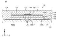
- FIG. FIG. 6 is a cross-sectional view taken along line YY in FIG. 4(a).
- the XYZ coordinate system is intended to facilitate understanding of the invention and is not intended to limit the invention.
- the X-axis direction indicates the length direction of the RFID module 130
- the Y-axis direction indicates the width direction of the RFID module 130
- the Z-axis direction indicates the thickness direction of the RFID module 130 .
- the X, Y and Z directions are orthogonal to each other.
- the RFID module 130 is attached to the first antenna pattern and the second antenna pattern 122b of the metal film 122 with the adhesive layer 139 interposed therebetween.
- the adhesive layer 139 is composed of, for example, an adhesive such as double-sided tape or synthetic resin.
- the RFID module 130 includes a substrate 133 and an RFIC element 134 mounted on the substrate 133 .
- the substrate 133 is, for example, a flexible substrate such as polyimide.
- a protective film 135 is formed on the first surface (upper surface in FIG. 5) of the substrate 133 on which the RFIC element 134 is mounted.
- the protective film 135 is, for example, an elastomer such as polyurethane or a hot melt agent such as ethylene vinyl acetate (EVA).
- EVA ethylene vinyl acetate
- a protective film 136 is also attached to the second surface of the substrate 133 (lower surface in FIG. 5).
- the protective film 136 is, for example, a coverlay film such as a polyimide film (Kapton tape).
- the third electrode 137, the fourth electrode 138, the conductor pattern L1a of the main part of the first inductance element L1, and the conductor pattern L2a of the main part of the second inductance element L2 are formed on the first surface of the substrate 133. It is The third electrode 137 is connected to one end of the conductor pattern L1a, and the fourth electrode 138 is connected to one end of the conductor pattern L2a.
- These conductor patterns are formed, for example, by patterning copper foil by photolithography.
- a first electrode 131 and a second electrode 132 are formed on the second surface of the substrate 133 to be capacitively coupled to the first side portion 122a and the second side portion 122b of the metal film 122, respectively. Further, on the second surface of the substrate 133, a conductor pattern L1b that is part of the first inductance element L1, and conductor patterns L3a, L3b (a conductor pattern surrounded by a two-dot chain line) and L3c of the third inductance element L3 are formed. There is These conductor patterns are also formed, for example, by patterning a copper foil by photolithography.
- the first electrode 131 is connected to one end of the conductor pattern L1b of the first inductance element L1 and one end of the conductor pattern L3a of the third inductance element L3.
- one end of the conductor pattern L2b of the second inductance element L2 and one end of the conductor pattern L3c of the third inductance element L3 are connected to the second electrode 132 .
- a conductor pattern L3b is connected between the other end of the conductor pattern L3a of the third inductance element L3 and the other end of the conductor pattern L3c.
- the other end of the conductor pattern L1b of the first inductance element L1 and the other end of the conductor pattern L1a of the first inductance element L1 are connected via a via conductor V1.
- the other end of the conductor pattern L2b of the second inductance element L2 and the other end of the conductor pattern L2a of the second inductance element L2 are connected via a via conductor V2.
- the RFIC element 134 is mounted on the third electrode 137 and the fourth electrode 138 formed on the first surface of the substrate 133 . That is, the first terminal 134 a of the RFIC element 134 is connected to the third electrode 137 and the second terminal 134 b of the RFIC element 134 is connected to the fourth electrode 138 .
- the conductor patterns L3a of the first inductance element L1 and the third inductance element L3 are formed in different layers of the substrate 133, respectively, and arranged so that their coil openings overlap each other.
- the conductor patterns L3c of the second inductance element L2 and the third inductance element L3 are formed in different layers of the substrate 133, respectively, and arranged such that their coil openings overlap.
- the RFIC element 134 is arranged on the surface of the substrate 133 between the conductor pattern L3c of the second inductance element L2 and the third inductance element L3 and the conductor pattern L3a of the first inductance element L1 and the third inductance element L3. ,To position.
- a first current path CP1 passing through the first and second surfaces of the substrate 133 and a second current path CP2 passing through the second surface of the substrate 133 are formed.
- the first current path CP1 extends from the first electrode 131 to the second electrode 132 through the branch point N1, the conductor pattern L1b, the conductor pattern L1a, the RFIC element 134, the conductor pattern L2a, the conductor pattern L2b, and the branch point N2.
- the second current path CP2 extends from the first electrode 131 to the second electrode 132 through the branch point N1, the conductor pattern L3a, the conductor pattern L3b, the conductor pattern L3c, and the branch point N2.
- the first inductance element L1 is composed of the conductor pattern L1b connected to the conductor pattern L1a via the via conductor V1
- the conductor pattern L2b is composed of the conductor pattern L2a connected to the conductor pattern L2a via the via conductor V2.
- the winding direction of the current flowing through the second inductance element L2 is reversed, and the magnetic field generated by the first inductance element L1 and the magnetic field generated by the second inductance element L2 cancel each other.
- the first current path CP1 and the second current path CP2 are formed in parallel with each other between the first electrode 131 and the second electrode 132, respectively.
- the RFID module 130 and the first and second antenna patterns 122a and 122b of the metal film 122 constitute a communication circuit.
- the first and second antenna patterns 122 a and 122 b of the metal film 122 function as dipole antennas for the RFID module 130 .
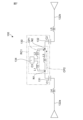
- FIG. 7 is a circuit diagram of an example of the circuit configuration of the container 100 with RFID function.
- the first current path CP1 is part of the parallel resonant circuit RC1, which is an LC parallel resonant circuit, and is matched to the radio waves of the communication frequency.
- RC1 parallel resonant circuit
- the RFID module 130 has a parallel resonant circuit RC1.
- the parallel resonant circuit RC1 is a loop circuit composed of the first inductance element L1, the RFIC element 134, the second inductance element L2, and the third inductance element L3.
- the first and second electrodes 131, 132 of the RFID module 130 are capacitively coupled to the first and second antenna patterns 122a, 122b, respectively.
- a capacitive component C1 between the first electrode 131 and the first antenna pattern 122a is composed of the first antenna pattern 122a, the first electrode 131, the adhesive layer 139, and the protective film 136.
- FIG. A capacitive component C2 between the second electrode 132 and the second antenna pattern 122b is composed of the second antenna pattern 122b, the second electrode 132, the adhesive layer 139, and the protective film 136.
- the first antenna pattern 122a has an inductance component and acts as a fourth inductance element L4.
- the second antenna pattern 122b has an inductance component and acts as a fifth inductance element L5.
- the parallel resonant circuit RC1 is designed to perform LC parallel resonance with impedance matching for radio waves at communication frequencies. Therefore, the parallel resonant circuit RC1 acts as a filter circuit that transmits to the RFIC element 134 the current due to the electromagnetic waves of the inherent resonant frequency, which is the communication frequency. Thereby, the communication frequency is matched with the RFIC element 134, and the communication distance of the RFID module 130 at the communication frequency can be secured.
- the RFID function-equipped container 100 includes an electrically insulating main body 110 having an accommodation space 111 for the content N100, and a metal film 122 attached to the main body 110 so as to cover the opening of the accommodation space 111. It comprises a lid 120 and an RFID module 130 having first and second electrodes 131 , 132 attached to the lid 120 so as to be outside the opening of the receiving space 111 and coupled to the metal film 122 .
- the function as an RFID tag is realized by connecting the RFID module 130 to the metal film 122 of the lid 120. Since the metal film 122 formed on the lid 120 is used to protect the contents N100, etc., there is no need to separately provide an antenna or the like just for the RFID function. Since the RFID module 130 is located outside the opening of the housing space 111 in the lid 120, even if the RFID module 130 falls off the lid 120 unintentionally, the possibility of the RFID module 130 being mixed with the contents N100 is reduced. can.
- the RFID function-equipped container 100 of the present embodiment is a container in which the lid 120 having the metal film 122 is attached to the main body 110 that accommodates the content N100, and the RFID module 130 is provided while suppressing the deterioration of the design. can reduce the possibility of mixing into the contents N100.
- the metal film 122 includes antenna patterns (first and second antenna patterns 122a, 122b).
- the RFID module 130 is on the lid 120 such that the first and second electrodes 131, 132 are coupled to the antenna patterns (first and second antenna patterns 122a, 122b). This configuration can improve the efficiency of wireless communication in the RFID module 130 because the metal film 122 has an antenna pattern.
- the antenna patterns include first and second antenna patterns 122a and 122b that are electrically independent of each other.
- the RFID module 130 is on the lid 120 such that the first and second electrodes 131, 132 are respectively coupled to the first and second antenna patterns 122a, 122b. This configuration can form a dipole antenna.
- the shapes of the first and second antenna patterns 122 a and 122 b are defined by slits 123 formed in the metal film 122 .
- the slit 123 is arranged in the metal film 122 so as to avoid the predetermined region R100 covering the opening of the accommodation space 111 . This configuration allows provision of the first and second antenna patterns 122a and 122b without affecting the protection function of the contents N100 by the metal film 122.
- the slit 123 is formed so as to surround the opening of the accommodation space 111 and electrically separates the first and second antenna patterns 122a and 122b from the predetermined region R100. and second portions 123b-1 to 123b-4 formed at the edge of the opening of the space 111 to electrically isolate the first and second antenna patterns 122a and 122b. This configuration can reduce the possibility that the first and second antenna patterns 122a, 122b are affected by the content N100.
- the main body 110 has a flange portion 113 that protrudes outward from the opening edge of the accommodation space 111 .
- the RFID module 130 is located at a portion of the lid 120 facing the flange portion 113 . This configuration can reduce the possibility of impairing the function of the RFID module 130 when the containers 100 with RFID function are stacked.
- the lid 120 has a protective film 124 that covers the metal film 122 .
- RFID module 130 is between protective membrane 124 and metal membrane 122 . This configuration can reduce the likelihood that RFID module 130 will fall off lid 120 .
- the RFID module 130 is on the main body 110 side of the lid 120 . This configuration makes it difficult for the design of the container 100 with RFID function to be impaired. This configuration makes it difficult for the RFID module 130 to fall off.
- the RFID module 130 includes an RFIC element 134 and a filter circuit RC1 that transmits to the RFIC element 134 a current generated by electromagnetic waves having a unique resonance frequency, which is the communication frequency.
- the first electrode 131 and the second electrode 132 are connected to the filter circuit RC1.
- the RFIC element 134 and the metal film 122 are matched at the communication frequency, and the communication distance of the RFID module 130 at the communication frequency can be secured.
- Embodiment 1 is not limited to the above configuration. Embodiment 1 can be modified in various ways according to the design and the like, as long as the problem can be achieved. Modifications of the first embodiment are listed below. Modifications described below can be applied in combination as appropriate.
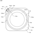
- FIG. 8 is a bottom view of a configuration example of lid 120A of the container with RFID function according to Modification 1 of Embodiment 1.
- Lid 120A includes metal film 122A having slit 123A formed therein.
- the slit 123A in FIG. 8 is arranged in the metal film 122A so as to avoid the predetermined region R100 covering the opening of the accommodation space 111 of the main body 110.
- a slit 123A in FIG. 8 has a different shape from the slit 123 in FIG.
- the slit 123A in FIG. 8 includes a frame portion 123a and first and fourth extension portions 123b-1 and 123b-4. Unlike slit 123, slit 123A does not include second and third extensions 123b-2 and 123b-3.
- the metal film 122A is divided into first side portions 122f corresponding to two adjacent four sides of the metal film 122A and second side portions 122g corresponding to the remaining two adjacent four sides of the metal film 122A. , and a central portion 122 e that covers the opening of the accommodation space 111 .
- the first and second side portions 122f and 122g and the central portion 122e are electrically isolated from each other.
- the first and second sides 122f, 122g can be used as antenna patterns for the RFID module 130.
- FIG. In FIG. 8, the first and second side portions 122f and 122g form electrically independent first and second antenna patterns.
- the first side portion 122f may be referred to as the first antenna pattern 122f
- the second side portion 122g may be referred to as the second antenna pattern 122g.
- the RFID module 130 is coupled to the metal film 122A in the lid 120A so as to straddle the first extension 123b-1 of the slit 123A. More specifically, RFID module 130 resides on lid 120A such that first and second electrodes 131, 132 are coupled to first and second antenna patterns 122f, 122g, respectively. The first and second electrodes 131, 132 are capacitively coupled to the first and second antenna patterns 122f, 122g, respectively.
- the antenna pattern can be made longer than in the lid 120 of FIG. This improves the degree of freedom for the length of the antenna pattern. Therefore, it is more likely that the length of the antenna pattern can be set to a length suitable for the wavelength corresponding to the communication frequency of the RFID module 130 .
- a suitable length for the wavelength corresponding to the communication frequency of RFID module 130 is, for example, 1 ⁇ 2 of the wavelength corresponding to the communication frequency of RFID module 130 .
- FIG. 9 is a bottom view of a configuration example of lid 120B of a container with an RFID function according to Modification 2 of Embodiment 1.
- FIG. Lid 120B includes metal film 122B having slit 123B formed therein.
- the slit 123B in FIG. 9 is arranged in the metal film 122B so as to avoid the predetermined region R100 covering the opening of the housing space 111 of the main body 110.
- a slit 123B in FIG. 9 has a different shape from the slit 123 in FIG.
- the slit 123B in FIG. 9 includes a frame portion 123a and a first extension portion 123b-1. Unlike slit 123, slit 123B does not include second through fourth extensions 123b-2 through 123b-4.
- the slit 123B divides the metal film 122B into a peripheral portion 122h corresponding to the four sides of the metal film 122A and a central portion 122e covering the opening of the accommodation space 111.
- peripheral portion 122h and central portion 122e are electrically isolated from each other.
- the peripheral portion 122h has a shape surrounding the central portion 122e, but is separated at the first extension portion 123b-1. Accordingly, the peripheral portion 122h has first and second ends 122ha and 122hb facing each other across the first extension portion 123b-1.
- Periphery 122 h can be used as a loop antenna pattern for RFID module 130 . Below, peripheral part 122h may be called loop antenna pattern 122h.
- the RFID module 130 is coupled to the metal film 122B in the lid 120B so as to straddle the first extension 123b-1 of the slit 123B. More specifically, the RFID module 130 is on the lid 120B such that the first and second electrodes 131, 132 are respectively coupled to the first end 122ha and the second end 122hb of the loop antenna pattern 122h. The first and second electrodes 131, 132 are capacitively coupled to the first end 122ha and the second end 122hb of the loop antenna pattern 122h, respectively.
- the loop antenna pattern 122h of the metal film 122B functions as a loop antenna for the RFID module 130.
- the metal film 122B includes an antenna pattern (loop antenna pattern 122h).
- the RFID module 130 is on the lid 120B such that the first and second electrodes 131, 132 are coupled to the antenna pattern (loop antenna pattern 122h). This configuration can improve the efficiency of wireless communication in the RFID module 130 because the metal film 122B has an antenna pattern.
- the antenna pattern includes a loop antenna pattern 122h.
- the RFID module 130 is on the lid 120B such that the first and second electrodes 131, 132 are respectively coupled to the first and second ends 122ha, 122hb of the loop antenna pattern 122h. This configuration can form a loop antenna.
- the shape of the loop antenna pattern 122h is defined by the slit 123B formed in the metal film 122B.
- the slit 123B is arranged to avoid the predetermined region R100 covering the opening of the accommodation space 111 in the metal film 122B. This configuration allows provision of the loop antenna pattern 122h without affecting the protection function of the contents N100 by the metal film 122B.
- FIG. 10 is a bottom view of a configuration example of lid 120C of a container with RFID function according to Modification 3 of Embodiment 1.
- FIG. Lid 120C includes metal film 122C having slit 123C formed therein.
- the slit 123C in FIG. 10 is arranged in the metal film 122C so as to avoid the predetermined region R100 covering the opening of the housing space 111 of the main body 110.
- a slit 123C in FIG. 10 has a different shape from the slit 123 in FIG.
- the slit 123C in FIG. 10 is formed at a corner of the metal film 122C facing the flange portion 113 of the main body 110. As shown in FIG.
- the slit 123C has a first side portion 123c, a second side portion 123d, and first and second extension portions 123e and 123f.
- the first side portion 123c extends from a predetermined corner (upper right corner in FIG. 10) of the metal film 122C toward the center of the metal film 122C.
- the second side portion 123d extends from the tip of the first side portion 123c in a direction perpendicular to the length direction of the first side portion 123c.
- the first and second extensions 123e and 123f extend along the adjacent sides of the metal film 122C from both longitudinal ends of the second side 123d.
- the slit 123C forms a loop antenna pattern 122i around the slit 123C in the metal film 122C.
- the loop antenna pattern 122i has a shape surrounding the slit 123C, but is separated at the first side portion 123c of the slit 123C. Accordingly, the loop antenna pattern 122i has first and second ends 122ia and 122ib facing each other across the first side portion 123c.
- the RFID module 130 is coupled to the metal film 122C in the lid 120C so as to straddle the first side 123c of the slit 123C. More specifically, the RFID module 130 is on the lid 120C such that the first and second electrodes 131, 132 are respectively coupled to the first end 122ia and the second end 122ib of the loop antenna pattern 122i. Also in FIG. 10, the RFID module 130 is located at a portion facing the flange portion 113 on the lid 120C. The first and second electrodes 131, 132 are capacitively coupled to the first end 122ia and the second end 122ib of the loop antenna pattern 122i, respectively.
- the loop antenna pattern 122i of the metal film 122C functions as a loop antenna for the RFID module 130.
- FIG. 11 is a bottom view of a configuration example of lid 120D of a container with RFID function according to Modification 4 of Embodiment 1.
- FIG. Lid 120D includes metal film 122D having slit 123D formed therein.
- the slit 123D in FIG. 11 is arranged in the metal film 122D so as to avoid the predetermined region R100 covering the opening of the housing space 111 of the main body 110.
- a slit 123D in FIG. 11 has a different shape from the slit 123 in FIG.
- the slit 123D in FIG. 11 is formed at a corner of the metal film 122D facing the flange portion 113 of the main body 110.
- the slit 123D has a first side portion 123g, a second side portion 123h, and a third side portion 123i.
- the first side portion 123g extends from a predetermined corner (upper right corner in FIG. 11) of the metal film 122D toward the center of the metal film 122D.
- the second side portion 123h extends from the tip of the first side portion 123g in a direction perpendicular to the length direction of the first side portion 123g.
- the third side portion 123i extends along the edge of the metal film 122D adjacent to the tip of the second side portion 123h.
- the slit 123D forms a loop antenna pattern 122j around the slit 123D in the metal film 122D.
- the loop antenna pattern 122j has a shape surrounding the slit 123D, but is separated at the first side 123g of the slit 123D. Accordingly, the loop antenna pattern 122j has first and second ends 122ja and 122jb facing each other across the first side portion 123g.
- the RFID module 130 is coupled to the metal film 122D in the lid 120D so as to straddle the first side 123g of the slit 123D. More specifically, the RFID module 130 is on the lid 120D such that the first and second electrodes 131, 132 are respectively coupled to the first end 122ja and the second end 122jb of the loop antenna pattern 122j. Also in FIG. 11, the RFID module 130 is located at a portion facing the flange portion 113 on the lid 120D. The first and second electrodes 131, 132 are capacitively coupled to the first end 122ja and the second end 122jb of the loop antenna pattern 122j, respectively.
- the loop antenna pattern 122j of the metal film 122D functions as a loop antenna for the RFID module 130.
- FIG. 12 is a bottom view of a configuration example of lid 120E of a container with RFID function according to Modification 5 of Embodiment 1.
- the lid 120E includes a metal film 122E with slits 123E formed therein.
- the slit 123E in FIG. 12 is arranged in the metal film 122E so as to avoid the predetermined region R100 covering the opening of the accommodation space 111 of the main body 110.
- a slit 123E in FIG. 12 has a different shape from the slit 123 in FIG.
- the slit 123E in FIG. 12 is formed along a predetermined direction in a portion of the metal film 122E corresponding to the edge of the opening of the accommodation space 111.
- the predetermined direction is the direction along the side of the metal film 122E adjacent to the slit 123E (vertical direction in FIG. 12).
- the slit 123E divides the metal film 122E into a first portion 122k corresponding to one of the four sides of the metal film 122E (the left side in FIG. 12) and a second portion 122l remaining in the metal film 122E.
- the second part 122l includes a predetermined region R100 that covers the opening of the accommodation space 111.
- the first and second parts 122k, 122l are electrically separated from each other by the slit 123E.
- the first and second portions 122k, 122l can be used as antenna patterns for the RFID module 130.
- FIG. In FIG. 12, the first and second parts 122k, 122l form electrically independent first and second antenna patterns.
- the first portion 122k may be referred to as the first antenna pattern 122k
- the second portion 122l may be referred to as the second antenna pattern 122l.
- the RFID module 130 is coupled to the metal film 122E across the slit 123E in the lid 120E. More specifically, the RFID module 130 is on the lid 120E such that the first and second electrodes 131, 132 are respectively coupled to the first and second antenna patterns 122k, 122l. Also in FIG. 12, the RFID module 130 is located at a portion facing the flange portion 113 on the lid 120E. The first and second electrodes 131, 132 are capacitively coupled to the first and second antenna patterns 122k, 122l, respectively.
- the first and second antenna patterns 122k, 122l of the metal film 122E function as dipole antennas for the RFID module 130.
- a slit 123E is formed along a predetermined direction in the lid 120E of FIG.
- the slit 123E is formed on a straight line along a predetermined direction. Therefore, it is possible to collectively form the slits 123E in the plurality of lids 120E.
- FIG. An example of a method for manufacturing the lid 120E includes first, second, and third steps.
- FIG. 13 is an explanatory diagram of the first step of one example of the method of manufacturing the lid 120E.
- a first step prepares a sheet 140 having a size capable of forming a plurality of lids 120E.
- sheet 140 is sized to form 16 lids 120E.
- the sheet 140 includes formation planned regions R120 for the lids 120E arranged in a 4 ⁇ 4 matrix.
- the sheet 140 is configured by forming a metal layer, which is the base of the metal film 122E of the lid 120E, on a base layer, which is the base of the base 121 of the lid 120E.
- a portion R121 of the sheet 140 other than the formation scheduled region R120 is a portion not used for the lid 120E.
- FIG. 14 is an explanatory diagram of the second step of one example of the method of manufacturing the lid 120E.
- the second step is to form the grooves 150 in the metal layer of the sheet 140 prepared in the first step. Portions of the grooves 150 corresponding to the respective formation-scheduled regions R120 serve as slits 123E.
- one groove 150 is formed along a predetermined direction in a plurality of (four in FIG. 14) formation scheduled regions R120 aligned in a predetermined direction. As a result, a plurality of (four in FIG. 14) slits 123E are collectively formed.
- FIG. 15 is an explanatory diagram of the third step of one example of the method of manufacturing the lid 120E.
- a plurality of RFID modules 130 are arranged in respective formation-planned regions R120 of a plurality of lids 120E.
- the sheet 140 is cut and separated into a plurality of lids 120E.
- the cutting of the sheet 140 may be performed after the sheet 140 is collectively attached to the plurality of bodies 110 .
- the slit 123E is formed along a predetermined direction in a portion of the metal film 122E corresponding to the edge of the opening of the accommodation space 111 to electrically connect the first and second antenna patterns 122k and 122l. physically separated. This configuration makes it possible to collectively form the slits 123E in a plurality of lids 120E.
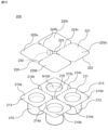
- FIG. 16 is an exploded perspective view of a configuration example of the RFID function-equipped container 200 according to the second embodiment.
- the RFID function-equipped container 200 of FIG. 16 is configured by a set of a plurality of containers.
- the RFID function-equipped container 200 of FIG. 16 can be used, for example, for goods traded in a pack of four.
- the RFID function-equipped container 200 in FIG. 1 The RFID function-equipped container 200 in FIG.
- a main body 210 in FIG. 16 has a plurality of (four in FIG. 16) housing spaces 211 for contents N100.
- Body 210 has electrical insulation.
- Body 210 is formed from a dielectric material such as paper, plastic, or glass, for example.
- the main body 210 in FIG. 16 has a plurality of (four in FIG. 16) small main body portions 215a to 215d.
- Each of the plurality of small body portions 215a to 215d has a bottomed cylindrical portion 212 and a flange portion 213.
- the tubular portion 212 defines the accommodation space 211 .
- the tubular portion 212 in FIG. 16 is cylindrical.
- the flange portion 213 protrudes outward from the opening edge of the housing space 211 .
- the external shape of the flange portion 213 in FIG. 16 is square.
- the four small main bodies 215 are arranged so that the accommodation space 211 surrounds a predetermined portion.
- the predetermined portion is the central portion of main body 210 .
- the four small main bodies 215a to 215d are arranged in a 2 ⁇ 2 matrix.
- the central portion of body 210 has an opening 216 surrounded by four smaller body portions 215a-215d.
- the four small main body portions 215a to 215d are connected to each other by the flange portion 213.
- a perforation 214a is formed between the flange portions 213 of the adjacent small main body portions 215a and 215b.
- the perforations 214a are used to separate the small body portions 215a and 215b.
- a perforation 214b is formed between the flange portions 213 of the adjacent small main body portions 215a and 215c.
- the perforations 214b are used to separate the small body portions 215a and 215c from each other.
- a perforation 214c is formed between the flange portions 213 of the adjacent small main body portions 215c and 215d.
- the perforations 214c are used to separate the small body portions 215c and 215d.
- a perforation 214d is formed between the flange portions 213 of the adjacent small main body portions 215b and 215d.
- the perforations 214d are used to separate the small body portions 215b and 215d.
- Each of the perforations 214a to 214d is composed of a plurality of slits arranged between the pair of storage spaces 211 in the main body 210 in a direction intersecting the direction in which the pair of storage spaces 211 are adjacent to each other.
- Perforations (first perforations) 214a to 214d of the main body 210 allow the small main body portions 215a to 215d to be separated from each other.
- a lid 220 in FIG. 16 is attached to the main body 210 so as to cover the openings of the plurality of accommodation spaces 211 .
- Lid 220 in FIG. 16 is releasably attached to body 210 .
- the lid 220 is peeled off from the main body 210 when the content N100 is taken out from the housing space 211 of the main body 210 .
- Lid 220 is generally flexible.
- the lid 220 in FIG. 16 has a plurality of (four in FIG. 16) small lid portions 225a to 225d.
- the plurality of small lid portions 225a-225d correspond to the plurality of small main body portions 215a-215d of the main body 210, respectively.
- small main bodies 215a to 215d and small lids 225a to 225d corresponding to the small main bodies 215a to 215d constitute a small container.
- Lid 220 includes base material 221 and metal film 222 .
- the base material 221 covers the openings of the housing spaces 211 of the plurality of small main bodies 215a to 215d.
- the base material 221 entirely covers the openings of the accommodating spaces 211 and the flange portions 213 of the plurality of small body portions 215a to 215d.
- the outer shape of the base material 221 is square.
- Substrate 221 is formed from, for example, a dielectric material such as paper or plastic.
- the metal film 222 comprehensively covers the openings of the housing spaces 211 of the plurality of small main bodies 215a to 215d.
- the metal film 222 comprehensively covers the openings of the accommodating spaces 211 and the flange portions 213 of the plurality of small main body portions 215a to 215d.
- the metal film 222 is on the surface of the base material 221 on the main body 210 side.
- the metal film 222 can act to prevent changes in the contents due to external factors.
- the metal film 222 protects the content N100 by covering the opening of the accommodation space 211 of the small body portion 215.
- Materials for the metal film 222 include aluminum and alloys containing aluminum.
- the four small lid portions 225a to 225d are arranged in a 2 ⁇ 2 matrix. At the center of the lid 220 is an opening 226 surrounded by four small lid portions 225a-225d. The opening 226 is located in the lid 220 at a position corresponding to a predetermined portion (central portion) of the main body 210 .
- the four small lid portions 225a-225d are connected to each other.
- a perforation 224a is formed between the adjacent small lid portions 225a and 225b in the lid 220. As shown in FIG.
- the perforations 224a are used to separate the small lid portions 225a and 225b from each other.
- a perforation 224b is formed between the adjacent small lid portions 225a and 225c in the lid 220.
- the perforations 224b are used to separate the small lid portions 225a and 225c from each other.
- a perforation 224c is formed between the adjacent small lid portions 225c and 225d in the lid 220.
- the perforations 224c are used to separate the small lid portions 225c and 225d.
- a perforation 224d is formed between the adjacent small lid portions 225b and 225d in the lid 220.
- the perforations 224d are used to separate the small lid portions 225b and 225d.
- the perforations 224a-224d are formed on the lid 220 at positions overlapping the perforations 214a-214d of the main body 210. As shown in FIG.
- each of the perforations 224a to 224d is composed of a plurality of slits arranged between the pair of storage spaces 211 in the main body 210 in a direction intersecting the direction in which the pair of storage spaces 211 are adjacent to each other.
- Perforations (second perforations) 224a to 224d of the lid 220 allow the small lid portions 225a to 225d to be separated from each other.
- the lid 220 is attached to the main body 210 by attaching the small lid portions 225a to 225d to the periphery of the opening of the housing space 211 of the small main body portions 215a to 215d with an adhesive.
- the small lid portions 225a-225d are adhesively attached to the flange portions 213 of the small body portions 215a-215d.
- the adhesive is applied to the areas facing the flange portion 213 in the small lid portions 225a to 225d.
- each small container 2 the small lid portions 225a to 225d are attached to the small main body portions 215a to 215d with an adhesive.
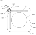
- FIG. 17 is a bottom view of the lid 220.
- the metal film 222 is on the entire surface of the lid 220 on the main body 210 side and comprehensively covers the housing space 211 of the main body 210 . Since the lid 220 has an opening 226 in the center, the metal film 222 does not exist in the area corresponding to the opening 226 .
- a slit 223 is formed in the metal film 222 .
- the slit 223 in FIG. 17 is arranged in the metal film 222 so as to avoid the predetermined region R200 that covers the opening of the housing space 211 of the main body 210 .
- a slit 223 in FIG. 17 is formed at a corner of the metal film 222 facing the flange portion 213 of the small main body portion 215a of the main body 210 . Slit 223 extends from opening 226 toward the opposite corner.
- a loop antenna pattern 222 a is formed around the opening 226 in the metal film 222 by the slit 223 .
- the loop antenna pattern 222a can generate a path through which current flows as indicated by a double-headed arrow A in FIG.
- Loop antenna pattern 222 a has a shape surrounding opening 226 , but is partially separated at slit 223 . Accordingly, the loop antenna pattern 222a has first and second ends 222aa and 222ab facing each other with the slit 223 therebetween.
- the RFID module 230 is the same as the RFID 130.
- RFID module 230 is coupled to metal film 222 across slit 223 in lid 220 . More specifically, the RFID module 230 is on the lid 220 such that the first and second electrodes 231, 232 are respectively coupled to the first end 222aa and the second end 222ab of the loop antenna pattern 222a. In FIG. 17 as well, the RFID module 230 is located at a portion of the lid 220 facing the flange portion 213 .
- the first and second electrodes 231, 232 are capacitively coupled to the first end 222aa and the second end 222ab of the loop antenna pattern 222a, respectively.
- the loop antenna pattern 222a of the metal film 222 functions as a loop antenna for the RFID module 230 before the RFID function-equipped container 200 is separated into small containers.
- the RFID modules 230 can communicate using the metal films 222 before the plurality of accommodation spaces 211 are individually separated.
- the metal film 222 is separated at the perforations 224 and the loop antenna pattern 222a is damaged. and will not function as a loop antenna. Therefore, after the RFID function-equipped container 200 is separated into small containers, the RFID function ceases to function. In other words, after the plurality of accommodation spaces 211 are individually separated, the RFID module 230 cannot communicate using the metal film 222 .
- the main body 210 has a plurality of accommodation spaces 211 arranged to surround predetermined portions.
- the metal film 222 comprehensively covers the plurality of accommodation spaces 211 .
- An opening 226 is formed in the lid 220 at a position corresponding to a predetermined portion.
- a slit 223 extending from the opening 226 is formed in the metal film 222 .
- the RFID module 230 is on the lid 220 across the slit 223 . This configuration suppresses deterioration in design in a container in which a lid 220 having a metal film 222 is attached to a main body 210 having a plurality of accommodation spaces 211 each accommodating a content N100.
- the RFID modules 230 can communicate using the metal films 222 before the plurality of accommodation spaces 211 are individually separated. On the other hand, after the plurality of accommodation spaces 211 are individually separated, the RFID module 230 cannot communicate using the metal film 222 .
- Embodiment 2 is not limited to the above configuration. Embodiment 2 can be modified in various ways according to the design, etc., as long as the problem can be achieved.
- a container with an RFID function which is a modified example of the second embodiment, will be described. This modification differs from the RFID function-equipped container 200 of the second embodiment in that a lid 220A shown in FIG. 18 is provided.
- FIG. 18 is a bottom view of a configuration example of a lid 220A of a container with an RFID function according to one modification of the second embodiment.
- the lid 220A in FIG. 18 is attached to the main body 210 so as to cover the openings of the plurality of accommodation spaces 211.
- Lid 220A in FIG. 18 is releasably attached to main body 210 .
- the lid 220A is peeled off from the main body 210 when the content N100 is taken out from the housing space 211 of the main body 210.
- Lid 220A is generally flexible.
- a lid 220A in FIG. 17 includes a base material 221A and a metal film 222A.
- the metal film 222A is on the entire surface of the lid 220 on the main body 210 side and comprehensively covers the housing space 211 of the main body 210 .
- Lid 220A in FIG. 17 has a plurality of small lid portions 225a to 225d, like lid 220 in FIG.
- the four small lid portions 225a to 225d are arranged in a 2 ⁇ 2 matrix. As described above, in the lid 220A, between the adjacent small lid portions 225a and 225b, between the adjacent small lid portions 225a and 225c, between the adjacent small lid portions 225c and 225d, and between the adjacent small lid portions 225b and 225d.
- each of the perforations 224a-224d is formed with perforations 224a to 224d, respectively.
- Each of the perforations 224a-224d is composed of a plurality of slits. By appropriately setting the size of the plurality of slits and the spacing of the plurality of slits, each of the perforations 224a to 224d is configured to substantially electrically isolate adjacent small lid portions.
- the portions of the metal film 222A corresponding to the small lid portions 225a and 225b can be used as electrically separated antenna patterns. Due to the perforations 224b, portions of the metal film 222A corresponding to the small lid portions 225a and 225c can be used as electrically separated antenna patterns. Due to the perforations 224c, portions of the metal film 222A corresponding to the small lid portions 225c and 225d can be used as electrically separated antenna patterns. Due to the perforations 224d, portions of the metal film 222A corresponding to the small lid portions 225b and 225d can be used as electrically separated antenna patterns.
- the RFID module 230 is outside the predetermined region R200 on the lid 220A and is coupled to the metal film 222A.
- the RFID module 230 is located at a portion of the lid 220A facing the flange portion 213 of the main body 210 .
- RFID module 230 is coupled to metal membrane 222A across perforations 224b in lid 220A. More specifically, the RFID module 230 is located on the lid 220A such that the first and second electrodes 231, 232 are coupled to portions of the metal film 222A corresponding to the small lid portions 225a, 225c, respectively. In this case, portions of the metal film 222A corresponding to the small lid portions 225a and 225c function as first and second antenna patterns.
- the first and second electrodes 231, 232 are capacitively coupled to the first and second antenna patterns, respectively.
- the first and second antenna patterns of the metal film 222A function as dipole antennas for the RFID module 230 before the container with RFID function is separated into small containers.
- the RFID module 230 can communicate using the metal film 222A before the plurality of accommodation spaces 211 are individually separated.
- the metal film 222A is separated by the perforations 224, so that at least one of the first and second antenna patterns and the RFID module 230 cannot maintain their connection. .
- RFID module 230 falls off lid 220A.
- the metal film 222A no longer functions as a dipole antenna for the RFID module 230.
- FIG. therefore, after the RFID function-equipped container is separated into small containers, the RFID function ceases to function. In other words, after the plurality of housing spaces 211 are individually separated, the RFID module 230 cannot communicate using the metal film 222A.
- the main body 210 has a pair of small main body portions 215a and 215b each having an accommodation space 211, and a first perforation 214a for separating the pair of small main body portions 215a and 215b.
- the lid 220 has a pair of small lid portions 225a and 225b respectively corresponding to the pair of small main body portions 215a and 215b, and a second perforation 224a for separating the pair of small lid portions 225a and 225b.
- the second perforations 224a electrically separate portions of the metal film 222 corresponding to the pair of small lid portions 225a and 225b.
- RFID module 230 is on lid 220A across second perforation 224a.
- the RFID module 230 can be used to store the content N100 while suppressing deterioration in design. can reduce the possibility of contamination with Also, before the plurality of accommodation spaces 211 are individually separated, the RFID module 230 can communicate using the metal film 222A. On the other hand, after the plurality of accommodation spaces 211 are individually separated, the RFID module 230 cannot communicate using the metal film 222A.
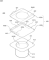
- FIG. 19 is an exploded perspective view of a configuration example of the RFID function-equipped container 300 according to the third embodiment.
- the RFID module 330 is the same as the RFID module 130 of the first embodiment.
- a main body 310 in FIG. 19 has an accommodation space 311 for the content N100.
- Body 310 has electrical insulation.
- the main body 310 is made of dielectric material such as paper, resin material, or glass, for example.
- the resin material includes expanded polystyrene, for example.
- the main body 310 in FIG. 19 has a cylindrical shape with a bottom.
- the body 310 of FIG. 19 has a cylindrical shape with a smaller diameter toward the bottom.
- a lid 320 in FIG. 19 is attached to the main body 310 so as to cover the opening of the accommodation space 311 .
- Lid 320 in FIG. 19 is releasably attached to body 310 .
- the lid 320 is peeled off from the main body 310 when the content N100 is taken out from the accommodation space 311 of the main body 310 .
- Lid 320 is generally flexible.
- the lid 320 has a main portion 320a and a handle portion 320b.
- the main portion 320 a covers the opening of the housing space 311 .
- the main portion 320a has a circular shape that covers the entire top surface of the main body 310 .
- the handle portion 320b protrudes outward from the main portion 320a.
- the handle portion 320b facilitates the work of peeling the lid 320 from the main body 310. - ⁇
- the handle portion 320b has a triangular shape whose width narrows as it protrudes from the main portion 320a.
- the lid 320 is attached to the periphery of the opening of the accommodation space 311 of the main body 310 with an adhesive.
- the adhesive is applied to an annular region R310 of the main portion 320a of the lid 320 facing the periphery of the opening of the housing space 311. As shown in FIG.
- the lid 320 includes a base material 321 and a metal film 322.
- the base material 321 covers the opening of the accommodation space 311 .
- the base material 321 entirely covers the opening of the accommodation space 311 and the peripheral portion of the opening of the accommodation space 311 .
- the outer shape of the base material 321 defines the outer shape of the lid 320 .
- Substrate 321 is formed from a dielectric material such as, for example, paper or plastic.
- the metal film 322 covers the opening of the accommodation space 311 of the main body 310 .
- the metal film 322 entirely covers the opening of the accommodation space 311 and the periphery of the opening of the accommodation space 311 .
- the metal film 322 is on the surface of the base material 321 on the main body 310 side.
- the metal film 322 can act to prevent changes in the contents due to external factors.
- the metal film 322 protects the content N100 by covering the opening of the accommodation space 311.
- Materials for the metal film 322 include aluminum and
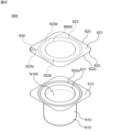
- FIG. 20 is a bottom view of the lid 320.
- the metal film 322 is divided into multiple parts. More specifically, the metal film 322 is divided into first and second side portions 322 a and 322 b corresponding to the outer edges of the metal film 322 and a central portion 322 c covering the opening of the accommodation space 311 .
- the center portion 322c includes a predetermined region R300 that covers the opening of the accommodation space 311 in the metal film 322.
- the first side portion 322 a includes a first portion 322 a 1 on the main portion 320 a of the lid 320 and a second portion 322 a 2 on the handle portion 320 b of the lid 320 .
- the second side portion 322 b includes a first portion 322 b 1 on the main portion 320 a of the lid 320 and a second portion 322 b 2 on the handle portion 320 b of the lid 320 .
- the first and second side portions 322a, 322b and the central portion 322c are electrically isolated from each other.
- the first and second sides 322 a , 322 b can be used as antenna patterns for the RFID module 330 .
- the first and second sides 322a and 322b form first and second antenna patterns that are electrically independent of each other.
- the first side portion 322a may be referred to as the first antenna pattern 322a
- the second side portion 322b may be referred to as the second antenna pattern 322b.
- a slit 323 formed in the metal film 322 divides the metal film 322 into first and second side portions 322 a and 322 b and a central portion 322 c covering the opening of the accommodation space 311 . Therefore, the shapes of the first and second antenna patterns 322 a and 322 b are defined by the slits 323 formed in the metal film 322 .
- the slit 323 is arranged in the metal film 322 so as to avoid the predetermined region R300 covering the opening of the accommodation space 311 of the main body 310 . Accordingly, the antenna patterns 322a and 322b can be provided without affecting the function of the metal film 322 to protect the contents N100.
- the 20 includes a first extension portion 323a, a frame portion 323b, and a second extension portion 323c.
- the frame portion 323b has an annular shape surrounding the predetermined region R100.
- the outer shape of the frame portion 323b is concentric with the main portion 320a of the lid 320.
- Each of the first and second extensions 323a and 323c extends outward from the lid 320 from the frame 323b.
- the first extension portion 323a extends from the frame portion 323b so as to divide the handle portion 320b of the lid 320 into two parts.
- the second extension portion 323c extends from the frame portion 323b in the opposite direction to the first extension portion 323a.
- the first and second extensions 323a, 323c are aligned.
- the frame portion 323b is a first portion formed to surround the opening of the accommodation space 311 and electrically separate the first and second antenna patterns 322a and 322b from the predetermined region R300.
- the first and second extensions 323a and 323c are second parts formed at the edge of the opening of the receiving space 311 to electrically separate the first and second antenna patterns 322a and 322b. Note that the slit 323 penetrates the metal film 322 but does not penetrate the base material 321 .
- the RFID module 330 is outside the predetermined region R300 on the lid 320 and is coupled to the metal film 122. As shown in FIG. That is, the RFID module 330 is outside the opening of the housing space 311 in the lid 320 and coupled to the metal film 322 . The RFID module 330 is located in the handle portion 320b of the lid 320. FIG. When the RFID function-equipped containers 300 are piled up during transportation or display of the RFID function-equipped containers 300, the main bodies 310 overlap each other. In the RFID function-equipped container 300, the RFID module 330 is located on the handle portion 320b of the lid 320, as described above.
- the RFID module 330 is less likely to be affected by another RFID-equipped container 300, particularly by the contents N100, than when the RFID module 330 is in the main portion 320a of the lid 320.
- FIG. therefore, when the RFID function-equipped container 300 of the present embodiment is stacked, the main body 310 overlaps with the RFID function-equipped container 300 , which reduces the possibility of impairing the function of the RFID module 330 .
- the RFID module 330 is coupled to the metal film 322 at the handle portion 320b of the lid 320 so as to straddle the first extension portion 323a of the slit 323. More specifically, the RFID module 330 is on the lid 320 such that the first and second electrodes 331, 332 are respectively coupled to the second portions 322a2, 322b2 of the first and second antenna patterns 322a, 322b. . In this embodiment, the first and second electrodes 331, 332 are capacitively coupled to the first and second antenna patterns 322a, 322b, respectively.
- the lid 320 may include a protective film that covers the metal film 322 .
- the RFID module 330 may be between the protective membrane and the metal membrane 322 . This reduces the possibility of the RFID module 330 falling off the lid 320 .
- the RFID function-equipped container 300 includes an electrically insulating main body 310 having an accommodation space 311 for the content N100, and a metal film 322 attached to the main body 310 so as to cover the opening of the accommodation space 311. It comprises a lid 320 and an RFID module 330 having first and second electrodes 331 , 332 attached to the lid 320 so as to be outside the opening of the receiving space 311 and coupled to the metal film 322 .
- the function as an RFID tag is realized by connecting the RFID module 330 to the metal film 322 of the lid 320. Since the metal film 322 of the lid 320 uses the metal film 322 formed on the lid 320 to protect the content N100, etc., there is no need to separately provide an antenna or the like just for the RFID function. Since the RFID module 330 is located outside the opening of the housing space 311 in the lid 320, even if the RFID module 330 falls off the lid 320 unintentionally, the possibility of the RFID module 330 being mixed with the contents N100 is reduced. can. As described above, the RFID function-equipped container 300 of the present embodiment is a container in which the lid 320 having the metal film 322 is attached to the main body 310 that accommodates the content N100. can reduce the possibility of mixing into the contents N100.
- the metal film 322 includes antenna patterns (first and second antenna patterns 322a, 322b).
- the RFID module 330 is on the lid 320 such that the first and second electrodes 331, 332 are coupled to the antenna patterns (first and second antenna patterns 322a, 322b). This configuration can improve the efficiency of wireless communication in the RFID module 330 because the metal film 322 has an antenna pattern.
- the antenna patterns include first and second antenna patterns 322a and 322b that are electrically independent of each other.
- the RFID module 330 is on the lid 320 such that the first and second electrodes 331, 332 are respectively coupled to the first and second antenna patterns 322a, 322b. This configuration can form a dipole antenna.
- the shapes of the first and second antenna patterns 322 a and 322 b are defined by slits 323 formed in the metal film 322 .
- the slit 323 is arranged in the metal film 322 so as to avoid the predetermined region R300 covering the opening of the accommodation space 311 . This configuration allows provision of the first and second antenna patterns 322a and 322b without affecting the protection function of the contents N100 by the metal film 322.
- the slit 323 is formed so as to surround the opening of the accommodation space 311 and electrically separates the first and second antenna patterns 322a and 322b from the predetermined region R300. and second portions 323a and 323c formed at the edge of the opening of the space 311 to electrically separate the first and second antenna patterns 322a and 322b. This configuration can reduce the likelihood that the first and second antenna patterns 322a, 322b will be affected by the content N100.
- the lid 320 has a handle portion 320 b protruding outward from the opening edge of the accommodation space 311 .
- RFID module 330 resides in handle portion 320b. This configuration can reduce the possibility of impairing the function of the RFID module 330 when the containers 300 with RFID function are stacked.
- the RFID module 330 is on the main body 310 side of the lid 320 . With this configuration, the design of the RFID-equipped container 300 is less likely to be impaired. This configuration makes the RFID module 330 less likely to fall off.
- Embodiment 3 is not limited to the above configuration. Embodiment 3 can be modified in various ways according to the design, etc., as long as the problem can be achieved. Modifications of the third embodiment are listed below. Modifications described below can be applied in combination as appropriate.
- FIG. 21 is a bottom view of a configuration example of lid 320A of a container with RFID function according to Modification 1 of Embodiment 3.
- FIG. The lid 320A includes a metal film 322A with slits 323A formed therein.
- the slit 323A in FIG. 21 is arranged in the metal film 322A so as to avoid the predetermined region R300 covering the opening of the accommodation space 311 of the main body 310.
- a slit 323A in FIG. 21 is different in shape from the slit 323 in FIG.
- the slit 323A of FIG. 21 includes a first extension portion 323a, an arc portion 323d, and second and third extension portions 323e and 323f.
- Arc portion 323d extends along the outer circumference of predetermined region R300. In FIG. 21, the central angle of the arc portion 323d is approximately 180 degrees.
- Each of the first to third extensions 323a, 323e, 323f extends outward from the lid 320A from the arc portion 323d.
- first extension portion 323a extends from the central portion of the arc portion 323d so as to bisect the handle portion 320b of the lid 320A.
- the second and third extension portions 323e and 323f extend outward from the lid 320A from both ends of the arc portion 323d.
- the second and third extensions 323e, 323f are aligned.
- the metal film 322A is divided by the slit 323A into first and second side portions 322e and 322f corresponding to 1/4 of the outer edge portion of the metal film 322A and a central portion 322d covering the opening of the accommodation space 311.
- the center portion 322d includes a predetermined region R300 covering the opening of the accommodation space 311 in the metal film 322 and 1/2 of the outer edge portion of the metal film 322A.
- the first side portion 322e includes a first portion 322e1 on the main portion 320a of the lid 320A and a second portion 322e2 on the handle portion 320b of the lid 320A.
- the second side portion 322f includes a first portion 322f1 on the main portion 320a of the lid 320A and a second portion 322f2 on the handle portion 320b of the lid 320A.
- the first and second side portions 322e and 322f and the central portion 322d are electrically isolated from each other.
- the first and second sides 322e, 322f can be used as antenna patterns for the RFID module 330.
- FIG. In FIG. 21, the first and second sides 322e and 322f form first and second antenna patterns that are electrically independent of each other.
- the first side portion 322e may be referred to as the first antenna pattern 322e
- the second side portion 322f may be referred to as the second antenna pattern 322f.
- the shapes of the first and second antenna patterns 322e and 322f are defined by slits 323A formed in the metal film 322A.
- the arc portion 323d and the second and third extension portions 323e and 323f are formed so as to surround the opening of the accommodation space 311 and electrically connect the first and second antenna patterns 322e and 322f from the predetermined region R300. It is the first part to be separated.
- the first extension part 323a is a second part formed at the edge of the opening of the accommodation space 311 and electrically separating the first and second antenna patterns 322e and 322f.
- the length of the arc portion 323d and the positions of the second and third extension portions 323e and 323f are appropriately set so that the lengths of the first and second antenna patterns 322e and 322f are set to desired lengths. Can be set. This improves the degree of freedom for the length of the antenna pattern. Therefore, it is more likely that the length of the antenna pattern can be set to a length suitable for the wavelength corresponding to the communication frequency of the RFID module 330 .
- a suitable length for the wavelength corresponding to the communication frequency of RFID module 330 is, for example, 1 ⁇ 2 of the wavelength corresponding to the communication frequency of RFID module 330 .
- FIG. 22 is a bottom view of a configuration example of a lid 320B of a container with an RFID function according to Modification 2 of Embodiment 3.
- FIG. The lid 320B includes a metal film 322B with slits 323B formed therein.
- the slit 323B in FIG. 22 is arranged in the metal film 322B so as to avoid the predetermined region R300 covering the opening of the housing space 311 of the main body 310.
- a slit 323B in FIG. 22 is different in shape from the slit 323 in FIG.
- a slit 323B in FIG. 22 includes a first extension portion 323a and a frame portion 323b, but does not include a second extension portion 323c.
- the slit 323B divides the metal film 322B into a central portion 322g that covers the opening of the housing space 311 and a peripheral portion 322h that surrounds the central portion 322g.
- the central portion 322g includes a predetermined region R300 that covers the opening of the accommodation space 311 in the metal film 322B.
- the peripheral portion 322h has a shape surrounding the central portion 322g, but is separated at the first extension portion 323a. Accordingly, the peripheral portion 322h has first and second ends 322ha and 322hb facing each other across the first extension portion 323a.
- Perimeter 322 h can be used as a loop antenna pattern for RFID module 330 . Below, peripheral part 322h may be called loop antenna pattern 322h.
- the RFID module 330 is coupled to the metal film 322B in the lid 320B so as to straddle the first extension 323a of the slit 323B. More specifically, the RFID module 330 is attached to the handle portion 320b of the lid 320B such that the first and second electrodes 331, 332 are respectively coupled to the first end 322ha and the second end 322hb of the loop antenna pattern 322h. be. The first and second electrodes 331, 332 are capacitively coupled to the first end 322ha and the second end 322hb of the loop antenna pattern 322h, respectively.
- the loop antenna pattern 322h of the metal film 322B functions as a loop antenna for the RFID module 330.
- the metal film 322B includes an antenna pattern (loop antenna pattern 322h).
- the RFID module 330 is on the lid 320B such that the first and second electrodes 331, 332 are coupled to the antenna pattern (loop antenna pattern 322h). This configuration can improve the efficiency of wireless communication in the RFID module 330 because the metal film 322B has an antenna pattern.
- the antenna pattern includes a loop antenna pattern 322h.
- RFID module 330 is on lid 320B such that first and second electrodes 331, 332 are respectively coupled to first and second ends 322ha, 322hb of loop antenna pattern 322h. This configuration can form a loop antenna.
- the shape of the loop antenna pattern 322h is defined by a slit 323B formed in the metal film 322B.
- the slit 323B is arranged in the metal film 322B so as to avoid the predetermined region R300 covering the opening of the accommodation space 311. As shown in FIG. This configuration allows provision of the loop antenna pattern 322h without affecting the protection function of the contents N100 by the metal film 322B.
- FIG. 23 is a bottom view of a configuration example of a lid 320C of a container with an RFID function according to Modification 3 of Embodiment 3.
- the lid 320C includes a metal film 322C with slits 323C formed therein.
- the slit 323C in FIG. 23 is arranged in the metal film 322C so as to avoid the predetermined region R300 covering the opening of the housing space 311 of the main body 310.
- a slit 323C in FIG. 23 is different in shape from the slit 323 in FIG.
- a slit 323C in FIG. 23 includes a first extension portion 323a and an arc portion 323g.
- Arc portion 323g extends along the outer circumference of predetermined region R300.
- the central angle of the arc portion 323g is approximately 90 degrees.
- the first extension portion 323a extends outward from the lid 320C from the arc portion 323g.
- the first extension portion 323a extends from the central portion of the arc portion 323g so as to bisect the handle portion 320b of the lid 320C.
- the slit 323C forms a loop antenna pattern 322i around the slit 323C in the metal film 322C.
- the loop antenna pattern 322i has a shape surrounding the slit 323C, but is separated at the first extension 323a of the slit 323C. Accordingly, the loop antenna pattern 322i has first and second ends 322ia and 322ib facing each other with the first extension portion 323a interposed therebetween.
- the RFID module 330 is coupled to the metal film 322C in the lid 320C so as to straddle the first extension 323a of the slit 323C. More specifically, the RFID module 330 is on the lid 320C such that the first and second electrodes 331, 332 are respectively coupled to the first end 322ia and the second end 322ib of the loop antenna pattern 322i. Also in FIG. 23, the RFID module 330 is in the handle portion 320b of the lid 320C. The first and second electrodes 331, 332 are capacitively coupled to the first end 322ia and the second end 322ib of the loop antenna pattern 322i, respectively.
- the loop antenna pattern 322i of the metal film 322C functions as a loop antenna for the RFID module 330.
- FIG. 24 is a bottom view of a configuration example of a lid 320D of a container with an RFID function according to Modification 4 of Embodiment 3.
- FIG. Lid 320D includes metal film 322D having slit 323D formed therein.
- the slit 323D in FIG. 24 is arranged in the metal film 322D so as to avoid the predetermined region R300 covering the opening of the housing space 311 of the main body 310.
- a slit 323D in FIG. 24 has a different shape from the slit 323 in FIG.
- the slit 323D in FIG. 24 is formed in a portion of the metal film 322D corresponding to the handle portion 320b of the lid 320D.
- the predetermined direction is orthogonal to the projecting direction of the handle portion 320 b from the main portion 320 a of the lid 320 .
- the slit 323D divides the metal film 322D into a first portion 322j corresponding to the tip of the handle portion 320b of the lid 320D in the metal film 322D and a second portion 322k remaining in the metal film 322D.
- the second portion 322k includes a predetermined region R300 that covers the opening of the accommodation space 311.
- the first and second parts 322j and 322k are electrically separated from each other by the slit 323D.
- the first and second portions 322j, 322k can be used as antenna patterns for the RFID module 330.
- FIG. In FIG. 24, the first and second parts 322j and 322k form electrically independent first and second antenna patterns.
- the first portion 322j may be referred to as the first antenna pattern 322j
- the second portion 322k may be referred to as the second antenna pattern 322k.
- the RFID module 330 is coupled to the metal film 322D across the slit 323D in the lid 320D. More specifically, RFID module 330 resides on lid 320D such that first and second electrodes 331, 332 are coupled to first and second antenna patterns 322j, 322k, respectively. Also in FIG. 24, the RFID module 330 is located in the handle portion 320b of the lid 320D. The first and second electrodes 331, 332 are capacitively coupled to the first and second antenna patterns 322j, 322k, respectively.
- the first and second antenna patterns 322j and 322k of the metal film 322D function as dipole antennas for the RFID module 330.
- a slit 323D is formed along a predetermined direction in the lid 320D of FIG.
- the slit 323D is formed on a straight line along a predetermined direction. Therefore, it is possible to collectively form slits 323D in a plurality of lids 320D.
- FIG. 25A and 25B are explanatory diagrams of an example of a method of manufacturing the lid 320D of FIG.
- An example of a method for manufacturing the lid 320D includes first, second, and third steps.
- the first step is to prepare a sheet 340 having a size capable of forming a plurality of lids 320D.
- sheet 340 is sized to form six lids 320D. More specifically, the sheet 340 includes formation planned regions R320 for the lids 320D arranged in a 2 ⁇ 3 matrix.
- the sheet 340 is configured by forming a metal layer, which is the base of the metal film 322D of the lid 320D, on a base layer, which is the base of the base 321 of the lid 320D.
- a portion R321 other than the formation scheduled region R320 on the sheet 340 is a portion not used for the lid 320D.
- the second step is to form grooves 350 in the metal layer of the sheet 340 prepared in the first step.
- the portions of the grooves 350 corresponding to the respective formation-scheduled regions R320 serve as slits 323D.
- one groove 350 is formed along a predetermined direction in a plurality of (three in FIG. 25) formation scheduled regions R320 aligned in a predetermined direction.
- a plurality of (three in FIG. 25) slits 323D are collectively formed.
- a plurality of RFID modules 330 are arranged in formation-planned regions R320 of a plurality of lids 320D.
- the sheet 340 is cut and separated into a plurality of lids 320D. Cutting the sheet 340 may be performed after the sheet 340 is attached to the plurality of bodies 310 together.
- the slit 323D is formed along a predetermined direction in a portion of the metal film 322D corresponding to the edge of the opening of the accommodation space 311 to electrically connect the first and second antenna patterns 322j and 322k. physically separated. This configuration makes it possible to collectively form the slits 323D in the plurality of lids 320D.
- FIG. 26 is an exploded perspective view of a configuration example of the RFID function-equipped container 400 according to the fourth embodiment.
- the RFID function-equipped container 400 of FIG. 26 includes a main body 410 , a lid 420 and an RFID module 430 .
- the RFID module 430 is the same as the RFID module 130 of the first embodiment.
- a main body 410 in FIG. 26 has an accommodation space 411 for the content N100.
- Body 410 has electrical insulation.
- the main body 410 is made of dielectric material such as paper, resin material, or glass, for example.
- the resin material includes expanded polystyrene, for example.
- a main body 410 in FIG. 26 has a bottomed tubular portion 412 and a flange portion 413 .
- the tubular portion 412 defines the accommodation space 411 .
- the tubular portion 412 in FIG. 26 is cylindrical.
- the flange portion 413 protrudes outward from the opening edge of the housing space 411 .
- the external shape of the flange portion 413 in FIG. 26 is square.
- a lid 420 in FIG. 26 is attached to the main body 410 so as to cover the opening of the accommodation space 411 .
- Lid 420 in FIG. 26 is releasably attached to body 410 .
- the lid 420 is peeled off from the main body 410 when the content N100 is taken out from the accommodation space 411 of the main body 410 .
- Lid 420 is generally flexible.
- the lid 420 is attached to the periphery of the opening of the accommodation space 411 of the main body 410 with an adhesive.
- the lid 420 is adhesively attached to the flange portion 413 of the body 410 .
- the adhesive is applied to a region of lid 420 facing flange portion 413 .
- a lid 420 in FIG. 26 includes an outer layer portion 420a and an inner layer portion 420b.
- the outer layer portion 420 a includes a base material 421 and a metal film 422 .
- the base material 421 covers the opening of the accommodation space 411 .
- the base material 421 entirely covers the opening of the accommodation space 411 and the flange portion 413 .
- the outer shape of the base material 421 is square.
- Substrate 421 is formed, for example, from a dielectric material such as paper or plastic.
- the metal film 422 covers the opening of the accommodation space 411 of the main body 410 .
- the metal film 422 entirely covers the opening of the accommodation space 411 and the flange portion 413 .
- the metal film 422 is on the surface of the base material 421 on the main body 410 side.
- the metal film 422 is not on the entire surface of the base material 421 on the main body 410 side, but on the central portion.
- the metal film 422 can act to prevent changes in the contents due to external factors.
- the metal film 422 protects the contents N100 by covering the opening of the accommodation space 411.
- Materials for the metal film 422 include aluminum and alloys containing aluminum.
- the inner layer portion 420 b has an insulating material 423 and first and second electrode patterns 441 and 442 .
- the insulating material 423 faces the metal film 422 .
- the insulating material 423 is sized to cover the metal film 422 .
- Insulating material 423 is formed from a dielectric material such as, for example, plastic.
- the outer shape of the insulating material 423 is equal to the outer shape of the base material 421 .
- the first and second electrode patterns 441 and 442 are formed on the insulating material 423 and coupled to the metal layer 422 . More specifically, the first and second electrode patterns 441 and 442 are formed on the surface of the insulating material 423 opposite to the metal film 422 (lower surface in FIG. 26).
- the first and second electrode patterns 441 and 442 are formed, for example, by patterning metal foil such as copper foil by photolithography.
- the first and second electrode patterns 441 and 442 are arranged in the metal film 422 so as to avoid the predetermined region R400 covering the opening of the housing space 411 of the main body 410.
- the first electrode pattern 441 includes a first electrode portion 441a and a first wiring portion 441b.
- the first electrode portion 441 a is located at a portion of the insulating material 423 that overlaps the metal film 422 .
- the first electrode portion 441 a is capacitively coupled with the metal film 422 .
- the first electrode part 441 a faces the metal film 422 and is larger than the first electrode 431 of the RFID module 430 .
- the first wiring portion 441 b extends from the first electrode portion 441 a to a portion of the insulating material 423 that does not overlap the metal film 422 .
- the first wiring portion 441 b is used to connect the first electrode portion 441 a and the first electrode 431 of the RFID module 430 .
- the second electrode pattern 442 includes a second electrode portion 442a and a second wiring portion 442b.
- the second electrode portion 442 a is located at a portion of the insulating material 423 that overlaps the metal film 422 .
- the second electrode portion 442 a is capacitively coupled with the metal film 422 .
- the second electrode part 442 a faces the metal film 422 and is larger than the second electrode 432 of the RFID module 430 .
- the second wiring portion 442 b extends from the second electrode portion 442 a to a portion of the insulating material 423 that does not overlap the metal film 422 .
- the second wiring portion 442 b is used to connect the second electrode portion 442 a and the second electrode 432 of the RFID module 430 .
- the inner layer portion 420b is bonded to the outer layer portion 420a such that the insulating material 423 of the inner layer portion 420b covers the metal film 422 of the outer layer portion 420a.
- a slit is not provided in the metal film 422 in the RFID function-equipped container 400 .
- the thickness of the metal film 422 may be limited.
- the metal film 422 does not need to be processed such as forming slits, so that the metal film 422 can be designed more freely.
- the thickness of the metal film 422 can be set to a desired thickness, and the effect of preventing changes in the contents due to external factors can be improved.
- FIG. 27 is a plan view of a configuration example of the lid 420.
- FIG. RFID module 430 is outside predetermined area R400 on lid 420 . More specifically, the RFID module 430 is located at a portion of the lid 420 facing the flange portion 413 of the main body 410 . Further, the RFID module 430 is arranged on a portion of the insulating material 423 that does not overlap the metal film 422 . The RFID module 430 is on the insulating material 423 such that the first and second electrodes 431, 432 are coupled to the first and second wiring portions 441b, 442b of the first and second electrode patterns 441, 442, respectively. The RFID module 430 is coupled to the metal film 422 through the first and second electrode patterns 441,442. This enables the RFID module 430 to communicate using the metal film 422 .
- the RFID module 430 is located at a portion of the lid 420 facing the flange portion 413 of the main body 410 . Therefore, the RFID module 430 is less affected by another container 400 with RFID function, particularly by the contents N100, than when the RFID module 430 is located in the lid 420 at a portion overlapping the housing space 411 of the main body 410. Hard to accept. Therefore, the possibility of impairing the function of the RFID module 430 can be reduced.
- lid 420 has first and second electrode patterns 441 and 442 coupled to metal film 422 .
- First and second electrodes 431, 432 of RFID module 430 are coupled to first and second electrode patterns 441, 442, respectively.
- This configuration does not require processing such as forming slits in the metal film 422, so that the degree of freedom in designing the metal film 422 can be improved.
- the thickness of the metal film 422 can be set to a desired thickness, and the effect of preventing changes in the contents due to external factors can be improved.
- the lid 420 has an insulating material 423 facing the metal film 422 and first and second electrode patterns 441 and 442 .
- the first and second electrode patterns 441 and 442 are arranged on the insulating material 423 .
- the first and second electrode patterns 441 and 442 face the metal film 422 .
- the RFID module 430 rests on the insulating material 423 such that the first and second electrodes 431, 432 are coupled to the first and second electrode patterns 441, 442 respectively.
- This configuration does not require processing such as forming slits in the metal film 422, so that the degree of freedom in designing the metal film 422 can be improved.
- the thickness of the metal film 422 can be set to a desired thickness, and the effect of preventing changes in the contents due to external factors can be improved.
- the first electrode pattern 441 includes a first electrode portion 441 a that faces the metal film 422 and is larger than the first electrode 431 of the RFID module 430 , and the first electrode portion 441 a and the first electrode 431 of the RFID module 430 . and a first wiring portion 441b for connecting the .
- the second electrode pattern 442 includes a second electrode portion 442 a that faces the metal film 422 and is larger than the second electrode 432 of the RFID module 430 , and a second electrode portion 442 a that connects the second electrode portion 442 a and the second electrode 432 of the RFID module 430 . and a wiring portion 442b. This configuration can strengthen the bond between the RFID module 430 and the metal film 422 .
- Embodiment 4 is not limited to the above configuration. Embodiment 4 can be modified in various ways according to the design, etc., as long as the problem can be achieved. Modifications of the fourth embodiment are listed below. Modifications described below can be applied in combination as appropriate.
- lid 420 may comprise a protective membrane.
- the protective film covers the surface of the insulating material 423 opposite to the metal film 422 .
- the protective film material is, for example, a hot melt agent such as ethylene vinyl acetate (EVA).
- EVA ethylene vinyl acetate
- RFID module 430 may be between the protective membrane and insulating material 423 . This reduces the possibility of the RFID module 430 falling off the lid 420 .
- the first and second electrode patterns 441 and 442 may be on the surface of the insulating material 423 on the metal film 422 side.
- the first and second electrode patterns 441 and 442 may be formed on the insulating material 423 so as to be combined with the metal film 422 .
- the RFID module 430 may be on the surface of the insulating material 423 facing the metal film 422 .
- the RFID module 430 may rest on the insulating material 423 such that the first and second electrodes 431, 432 are coupled to the first and second electrode patterns 441, 442, respectively.
- FIG. 28 is an exploded perspective view of a configuration example of the RFID function-equipped container 500 according to the fifth embodiment.
- the RFID function-equipped container 500 of FIG. 28 includes a main body 510 , a lid 520 and an RFID module 530 .
- the RFID module 530 is the same as the RFID module 130 of the first embodiment.
- a main body 510 in FIG. 28 has an accommodation space 511 for the content N100.
- Body 510 has electrical insulation.
- the main body 510 is made of dielectric material such as paper, resin material, or glass, for example.
- the resin material includes expanded polystyrene, for example.
- a main body 510 in FIG. 28 has a bottomed tubular portion 512 and a flange portion 513 .
- the tubular portion 512 defines a housing space 511 .
- the cylindrical portion 512 in FIG. 28 is cylindrical.
- the flange portion 513 protrudes outward from the opening edge of the housing space 511 .
- the external shape of the flange portion 513 in FIG. 28 is square.
- the flange portion 513 has first to fourth corner portions 513a to 513d.
- a lid 520 in FIG. 28 is attached to the main body 510 so as to cover the opening of the accommodation space 511 .
- Lid 520 in FIG. 28 is releasably attached to body 510 .
- the lid 520 is peeled off from the main body 510 when the content N100 is taken out from the accommodation space 511 of the main body 510 .
- Lid 520 is generally flexible.
- the lid 520 is attached to the periphery of the opening of the housing space 511 of the main body 510 with an adhesive.
- lid 520 is adhesively attached to flange portion 513 of body 510 .
- the adhesive is applied to a region of lid 520 facing flange portion 513 .
- the main body 510 has first and second electrode patterns 541 and 542 .
- the first and second electrode patterns 541 and 542 are formed on the body 510 and coupled to the metal layer 522 . More specifically, the first and second electrode patterns 541 and 542 are formed on the surface of the flange portion 513 of the main body 510 opposite to the metal film 522 (lower surface in FIG. 28).
- the first and second electrode patterns 541 and 542 are formed, for example, by patterning metal foil such as copper foil by photolithography.
- the first and second electrode patterns 541 and 542 are arranged avoiding the opening of the housing space 511 of the main body 510 .
- the first electrode pattern 541 includes a first electrode portion 541a and a first wiring portion 541b.
- the first electrode part 541 a faces the metal film 522 and is larger than the first electrode 531 of the RFID module 530 .
- the first electrode portion 541 a is formed using the second corner portion 513 b of the flange portion 513 . As a result, the area of the first electrode portion 541a can be increased, and the capacitive coupling between the metal film 522 and the first electrode portion 541a can be improved.
- the first wiring portion 541b extends from the first electrode portion 541a to the first corner portion 513a of the flange portion 513 .
- the first wiring portion 541 b is used to connect the first electrode portion 541 a and the first electrode 531 of the RFID module 530 .
- the second electrode pattern 542 includes a second electrode portion 542a and a second wiring portion 542b.
- the second electrode part 542 a faces the metal film 522 and is larger than the second electrode 532 of the RFID module 530 .
- the second electrode portion 542 a is formed using the third corner portion 513 c of the flange portion 513 .
- the second wiring portion 542b extends from the second electrode portion 542a to the first corner portion 513a of the flange portion 513 .
- the second wiring portion 542 b is used to connect the second electrode portion 542 a and the second electrode 523 of the RFID module 530 .
- a slit is not provided in the metal film 522 in the RFID function-equipped container 500 .
- the thickness of the metal film 522 may be limited.
- the metal film 522 does not need to be provided with slits or the like, so the degree of freedom in designing the metal film 522 can be improved.
- the thickness of the metal film 522 can be set to a desired thickness, and the effect of preventing changes in the contents due to external factors can be improved.
- FIG. 29 is a bottom view of main body 510.
- the RFID module 530 is outside the opening of the accommodation space 511 in the main body 510 . More specifically, RFID module 530 resides on flange portion 513 of body 510 .
- the RFID module 530 is located at the first corner 513a of the flange portion 513 such that the first and second electrodes 531 and 532 are coupled to the wiring portions 541b and 542b of the first and second electrode patterns 541 and 542, respectively. .
- the RFID module 530 is coupled to the metal film 522 through the first and second electrode patterns 541,542. This enables the RFID module 530 to communicate using the metal film 522 .
- the RFID module 530 is located on the flange portion 513 of the body 510 . Therefore, the RFID module 530 is less affected by another RFID-equipped container 500, particularly by the contents N100, than when the RFID module 530 is located in the lid 520 overlapping the housing space 511 of the main body 510. Hard to accept. Therefore, the possibility of impairing the function of the RFID module 530 can be reduced.
- the RFID function-equipped container 500 includes an electrically insulating main body 510 having a storage space 511 for the content N100, and a metal film 522 attached to the main body 510 so as to cover the opening of the storage space 511. It comprises a lid 520 and an RFID module 530 having first and second electrodes 531 , 532 attached to the body 510 so as to be outside the opening of the receiving space 511 and coupled to the metal film 522 .
- the RFID module 530 is coupled to the metal film 522 of the lid 520, thereby realizing the function as an RFID tag. Since the metal film 522 formed on the lid 520 is used to protect the contents N100, etc., there is no need to separately provide an antenna or the like just for the RFID function. Since the RFID module 530 is located outside the opening of the accommodation space 511 in the main body 510, even if the RFID module 530 unintentionally falls out of the main body 510, the possibility of the RFID module 530 being mixed with the contents N100 is reduced. can.
- the RFID function-equipped container 500 of the present embodiment is a container in which the lid 520 having the metal film 522 is attached to the main body 510 that accommodates the content N100, and the RFID module 530 can reduce the possibility of mixing into the contents N100.
- the main body 510 has first and second electrode patterns 541 and 542 coupled to the metal film 522 .
- the first and second electrodes 531, 532 of the RFID module 530 are coupled to the first and second electrode patterns 541, 542 respectively.
- This configuration does not require processing such as forming slits in the metal film 522, so that the degree of freedom in designing the metal film 522 can be improved.
- the thickness of the metal film 522 can be set to a desired thickness, and the effect of preventing changes in the contents due to external factors can be improved.
- the main body 510 has first and second electrode patterns 541 and 542 .
- the first and second electrode patterns 541 and 542 face the metal film 522 .
- RFID module 530 resides in body 510 such that first and second electrodes 531, 532 are coupled to first and second electrode patterns 541, 542, respectively.
- This configuration does not require processing such as forming slits in the metal film 522, so that the degree of freedom in designing the metal film 522 can be improved.
- the thickness of the metal film 522 can be set to a desired thickness, and the effect of preventing changes in the contents due to external factors can be improved.
- the metal film 522 is separated from the RFID module 530 by peeling off the lid 520 from the main body 510 . Therefore, the RFID function is disabled. In other words, whether the RFID function is enabled or disabled can be selected depending on whether the lid 520 is peeled off from the main body 510 .
- the first electrode pattern 541 includes a first electrode portion 541 a that faces the metal film 522 and is larger than the first electrode 531 of the RFID module 530 , and the first electrode portion 541 a and the first electrode 531 of the RFID module 530 . and a first wiring portion 541b for connecting the .
- the second electrode pattern 542 includes a second electrode portion 542 a that faces the metal film 522 and is larger than the second electrode 532 of the RFID module 530 , and a second electrode portion 542 a that connects the second electrode portion 542 a and the second electrode 532 of the RFID module 530 . and a wiring portion 542b. This configuration can strengthen the bond between the RFID module 530 and the metal film 522 .
- the main body 510 has a flange portion 513 that protrudes outward from the opening edge of the accommodation space 511 .
- a metal film 522 covers the flange portion 513 .
- the RFID module 530 and the first and second electrode patterns 541 , 542 are on the flange portion 513 . This configuration can reduce the possibility of impairing the function of the RFID module 530 when the containers 500 with RFID function are stacked.
- Embodiment 5 is not limited to the above configuration. Embodiment 5 can be modified in various ways according to the design, etc., as long as the problem can be achieved. Modifications of the fifth embodiment are listed below. Modifications described below can be applied in combination as appropriate.
- first and second electrode patterns 541 and 542 may be on the lid 520 side of the flange portion 513 .
- the first and second electrode patterns 541 and 542 may be formed on the body 510 so as to be combined with the metal layer 522 .
- the RFID module 530 may be on the surface of the flange portion 513 on the lid 520 side.
- the RFID module 530 may be on the body 510 such that the first and second electrodes 531, 532 are coupled to the first and second electrode patterns 541, 542, respectively.
- FIG. 30 is a perspective view of a configuration example of an RFID function-equipped container 600 according to the sixth embodiment.
- the RFID function-equipped container 600 of FIG. 30 is used, for example, in a system for identifying and managing whether or not the content N100 of the RFID function-equipped container 600 has been used, rather than identifying and managing commodities by wireless communication.
- the content N100 is, for example, an article for commercial transactions.
- Contents N100 can be liquid, solid, sol, gel, or combinations thereof. Examples of contents N100 include food, medicines, medical or orthodontic appliances, and the like.
- Foods include foods that can be provided in a container, such as yogurt, pudding, and instant foods.
- Medical or corrective devices include contact lenses.
- RFID function-equipped container 600 includes main body 610 , lid 620 , and RFID module 630 .
- FIG. 31 is a bottom view of a configuration example of the lid 620.
- FIG. FIG. 32 is a perspective view showing a state in which the lid 620 is peeled off from the main body 610 in the container 600 with RFID function.
- the main body 610 has an accommodation space 611 for the contents N100.
- Body 610 is electrically insulating.
- the main body 610 is made of dielectric material such as paper, resin material, or glass, for example.
- the resin material includes expanded polystyrene, for example.
- the main body 610 has a bottomed tubular portion 612 and a flange portion 613 .
- the tubular portion 612 defines a housing space 611 .
- the tubular portion 612 is cylindrical.
- the flange portion 613 protrudes outward from the opening edge of the housing space 611 .
- the outer shape of the flange portion 613 is square.
- the lid 620 is attached to the main body 610 so as to cover the opening of the accommodation space 611.
- Lid 620 in FIG. 30 is releasably attached to body 610 .
- the lid 620 is peeled off from the main body 610 when the content N100 is taken out from the accommodation space 611 of the main body 610 .
- Lid 620 is generally flexible.
- Lid 620 includes base material 621 and metal film 622 .
- the base material 621 covers the opening of the accommodation space 611 .
- the base material 621 entirely covers the opening of the accommodation space 611 and the flange portion 613 .
- the outer shape of the base material 621 is square.
- Substrate 621 is formed from a dielectric material such as, for example, paper or plastic.
- the metal film 622 covers the opening of the accommodation space 611 of the main body 610 .
- the metal film 622 entirely covers the opening of the housing space 611 and the flange portion 613 .
- the metal film 622 is on the surface of the base material 621 on the main body 610 side.
- the metal film 622 can act to prevent changes in the contents due to external factors. Thus, the metal film 622 protects the content N100 by covering the opening of the accommodation space 611.
- FIG. Materials for the metal film 622 include aluminum and alloys containing aluminum.
- the lid 620 is attached to the periphery of the opening of the accommodation space 611 of the main body 610 with an adhesive. In FIG. 30, the lid 620 is adhesively attached to the flange portion 613 of the body 610 . The adhesive is applied to a region of lid 620 facing flange portion 613 .
- the metal film 622 has a stripped portion 622a and residual portions (first and second residual portions) 622b and 622c.
- the peeled portion 622 a is a portion of the metal film 622 that is peeled off from the lid 620 and remains on the main body 610 when the lid 620 is peeled off from the main body 610 .
- the stripped portion 622 a is arranged in the metal film 622 so as to avoid the predetermined region R 600 covering the opening of the housing space 611 of the main body 610 .
- the peeled portion 622a has an annular shape surrounding the predetermined region R600.
- the first and second remaining portions 622 b and 622 c are portions of the metal film 622 that remain without being separated from the lid 620 when the lid 620 is separated from the main body 610 .
- the first remaining portion 622b is inside the stripped portion 622a.
- the first remaining portion 622b corresponds to the central portion of the metal film 622.
- the first remaining portion 622b is circular.
- the first remaining portion 622b includes a predetermined region R600 covering the opening of the accommodation space 611 of the main body 610 in the metal film 622.
- the second remaining portion 622c is outside the stripped portion 622a.
- the second residual portion 622 c corresponds to the peripheral portion of the metal film 622 .
- a groove portion 623a forming the slit 623 is formed in the second remaining portion 622c.
- the groove portion 623a is located at the corner of the metal film 622 and extends outward from the metal film 622 from the peeled portion 622a.
- the groove 623 a penetrates the metal film 622 .
- the second remaining portion 622c has a shape surrounding the peeled portion 622a, but is separated at the groove portion 623a.
- the second remaining portion 622c has first and second ends 622ca and 622cb facing each other across the groove portion 623a.
- the second remaining portion 622c forms an antenna pattern by peeling off the peeling portion 622a from the lid 620. As shown in FIG. In particular, in the present embodiment, the second remaining portion 622c forms a loop antenna pattern by peeling off the peeling portion 622a from the lid 620 .
- the RFID module 630 is coupled to the metal film 622 in the lid 620 so as to straddle the groove 623a of the slit 623 . More specifically, the RFID module 630 is attached to the lid 620 such that the first and second electrodes 631, 632 are respectively coupled to the first end 622ca and the second end 622cb of the second remnant portion 622c of the metal film 622. be. The first and second electrodes 631, 632 are capacitively coupled to the first end 622ca and the second end 622cb of the second residual portion 622c, respectively.
- the stripped portion 622 a is removed from the lid 620 by remaining on the body 610 when the lid 620 is peeled off from the body 610 .
- the first and second remaining portions 622b and 622c remain on the lid 620 even after the lid 620 is separated from the main body 610.
- metal film 622 is selectively removed when peeling lid 620 from body 610 .
- the peeled portion 622a and the first and second remaining portions 622b and 622c of the metal film 622 are different in strength of the adhesive between the lid 620 and the main body 610, thereby peeling the peeled portion 622a from the lid 620.
- the first and second residual portions 622b and 622c can be left on the lid 620 while the first and second residual portions 622b and 622c are left. Specifically, at the stripped portion 622a of the metal film 622, the strength of the adhesive may be made stronger than at the first and second remaining portions 622b and 622c. Also, if necessary, perforations may be formed at boundaries between the stripped portion 622a and the first and second remaining portions 622b and 622c.
- FIG. 33 is a bottom view of the lid 620 peeled off from the main body 610 in the container 600 with RFID function.
- the peeled portion 622 a is removed from the metal film 622 . Therefore, a penetrating portion 623b that penetrates the metal film 622 and exposes the base material 621 is formed at the trace of the peeled portion 622a.
- the penetrating portion 623b has a shape corresponding to the peeling portion 622a.
- the penetrating portion 623b connects to the groove portion 623a. Thereby, the slit 623 is formed by the penetrating portion 623b and the groove portion 623a.
- the slit 623 divides the metal film 622 into a first remaining portion 622b and a second remaining portion 622c.
- the first remaining portion 622b and the second remaining portion 622c are electrically separated from each other by the penetrating portion 623b.
- the second residual portion 622c is separated at the groove portion 623a as described above. This allows the second residual portion 622 c to be used as a loop antenna pattern for the RFID module 630 .
- the 2nd residual part 622c may be called loop antenna pattern 622c.
- the RFID module 630 is coupled to the metal film 622 in the lid 620 so as to straddle the groove 623a of the slit 623 .
- the loop antenna pattern 622 c of the metal film 622 functions as a loop antenna for the RFID module 630 . This enables the RFID module 630 to perform communication using the metal film 622 . Therefore, the RFID function is activated.
- RFID function-equipped container 600 includes main body 610 , lid 620 , and RFID module 630 .
- Body 610 is electrically insulating.
- the main body 610 has an accommodation space 611 for the contents N100.
- the lid 620 includes a metal film 622 and is attached to the main body 610 so as to cover the opening of the accommodation space 611 .
- the RFID module 630 is attached to the lid 620 so as to be outside the opening of the containing space 611 .
- the metal film 622 includes a peeled portion 622a that is peeled off from the lid 620 and remains on the main body 610 when the lid 620 is peeled off from the main body 610, and a peeled portion 622a that is not peeled off from the lid 620 when the lid 620 is peeled off from the main body 610 and is attached to the lid 620. and a residual portion 622c.
- the shape of the remaining portion 622c is defined by the stripped portion 622a.
- the remaining portion 622c is an antenna pattern having an antenna shape.
- the RFID module 630 has first and second electrodes 631 , 632 and is arranged on the lid 620 such that the first and second electrodes 631 , 632 are coupled to the remaining portion 622 c of the metal film 622 .
- This configuration can disable communication by the RFID module 630 when the lid 620 is attached to the body 610 and enable communication by the RFID module 630 when the lid 620 is peeled off the body 610 .
- the lid 620 has a groove 623 a penetrating the metal film 622 .
- the peeled portion 622 a leaves a penetrating portion 623 b connected to the groove portion 623 a in the metal film 622 .
- the through portion 623b and the groove portion 623a form a slit 623 that defines the antenna shape of the remaining portion 622c.
- the RFID function-equipped container 600 described above is configured such that the RFID function is disabled before the content N100 is used, and the RFID function is enabled after the content N100 is used.
- Information on products using the container 600 with RFID function cannot be read by the RFID function while the product is displayed in a shop.
- the RFID function can be used. Therefore, for example, in a product sales promotion campaign using the container 600 with RFID function, it is possible to correctly identify whether or not the product has been consumed, thereby preventing fraudulent campaigns.
- the RFID function is disabled before the content N100 is used, prevention of information leakage due to the RFID function can be expected.
- Embodiment 6 is not limited to the above configuration. Embodiment 6 can be modified in various ways according to the design, etc., as long as the problem can be achieved. Modifications of the sixth embodiment are listed below. Modifications described below can be applied in combination as appropriate.
- FIG. 34 is a bottom view of a configuration example of lid 620A of the RFID function-equipped container according to Modification 1 of Embodiment 6.
- FIG. Lid 620A includes metal film 622A.
- the metal film 622A has a stripped portion 622d and a remaining portion 622e.
- the peeled portion 622d is a portion of the metal film 622A that is peeled off from the lid 620A and remains on the main body 610 when the lid 620A is peeled off from the main body 610.
- FIG. The peeling portion 622d is arranged in the metal film 622A so as to avoid the predetermined region R600 covering the opening of the accommodation space 611 of the main body 610. As shown in FIG.
- the peeling portion 622d is L-shaped. The peeled portion 622d linearly extends from the corner of the metal film 622A along two sides forming the corner.
- the remaining portion 622e is a portion of the metal film 622A that remains without being separated from the lid 620A when the lid 620A is separated from the main body 610.
- FIG. The remaining portion 622e includes a predetermined region R600 that covers the opening of the accommodation space 611 of the main body 610 in the metal film 622A.
- a groove portion 623a forming a slit 623A is formed in the remaining portion 622e.
- the groove portion 623a is located at the corner of the metal film 622A and extends outward from the metal film 622A from the peeled portion 622d.
- a predetermined portion 622f around the peeled portion 622d in the remaining portion 622e is separated by the groove portion 623a.
- the predetermined portion 622f of the remaining portion 622e has first and second ends 622fa and 622fb facing each other across the groove portion 623a.
- a predetermined portion 622f of the remaining portion 622e forms an antenna pattern by peeling the peeling portion 622d from the lid 620A.
- a predetermined portion 622f of the remaining portion 622e constitutes a loop antenna pattern by peeling the peeling portion 622d from the lid 620A.
- the RFID module 630 is coupled to the metal film 622A in the lid 620A so as to straddle the groove 623a of the slit 623A. More specifically, in the RFID module 630, the first and second electrodes 631 and 632 are coupled (capacitively coupled) to the first end 622fa and the second end 622fb of the predetermined portion 622f of the residual portion 622e of the metal film 622A. As such, on lid 620A.
- FIG. 35 is a bottom view of the lid 620A separated from the main body 610 in the container with RFID function.
- the peeled portion 622d is removed from the metal film 622A. Therefore, a penetrating portion 623c that penetrates the metal film 622A and exposes the base material 621 is formed at the trace of the peeled portion 622d.
- the penetrating portion 623c has a shape corresponding to the peeling portion 622d.
- the through portion 623c connects to the groove portion 623a. Thereby, the through portion 623c and the groove portion 623a constitute the slit 623A.
- the slit 623A allows the predetermined portion 622f of the residual portion 622e to function as a loop antenna. Below, 622 f of predetermined parts may be called loop antenna pattern 622f.
- the loop antenna pattern 622f of the metal film 622A functions as a loop antenna for the RFID module 630. This enables the RFID module 630 to perform communication using the metal film 622A. Therefore, the RFID function is activated.
- FIG. 36 is a bottom view of a configuration example of a container lid 620B with an RFID function according to Modification 2 of Embodiment 6.
- FIG. Lid 620B includes metal film 622B.
- the metal film 622B has a stripped portion 622g and a remaining portion 622h.
- the peeled portion 622g is a portion of the metal film 622B that is peeled from the lid 620B and remains on the main body 610 when the lid 620B is peeled off from the main body 610.
- FIG. The peeled portion 622g is arranged in the metal film 622B so as to avoid the predetermined region R600 covering the opening of the housing space 611 of the main body 610.
- the stripped portion 622g is linear.
- the peeled portion 622g extends from the corner of the metal film 622B along one of the two sides forming the corner. In FIG. 36, the stripped portion 622g extends in the left-right direction.
- the remaining portion 622h is a portion of the metal film 622B that remains without being separated from the lid 620B when the lid 620B is separated from the main body 610.
- FIG. The remaining portion 622h includes a predetermined region R600 that covers the opening of the accommodation space 611 of the main body 610 in the metal film 622B.
- a groove portion 623a forming a slit 623B is formed in the remaining portion 622h.
- the groove 623a is located at the corner of the metal film 622B and extends outward from the metal film 622B from one end of the stripped portion 622g.
- a predetermined portion 622i around the peeled portion 622g in the residual portion 622h is separated by a groove portion 623a.
- the predetermined portion 622i of the remaining portion 622h has first and second ends 622ia and 622ib facing each other with the groove portion 623a interposed therebetween.
- a predetermined portion 622i of the remaining portion 622h forms a loop antenna pattern by peeling the peeling portion 622g from the lid 620B.
- the RFID module 630 is coupled to the metal film 622B in the lid 620B so as to straddle the groove 623a of the slit 623B. More specifically, in the RFID module 630, the first and second electrodes 631, 632 are coupled (capacitively coupled) to the first end 622ia and the second end 622ib of the predetermined portion 622i of the remaining portion 622h of the metal film 622B. As such, on lid 620B.
- FIG. 37 is a bottom view of the lid 620B separated from the main body 610 in the container with RFID function.
- the peeled portion 622g is removed from the metal film 622B. Therefore, a penetrating portion 623e that penetrates the metal film 622B and exposes the base material 621 is formed at the trace of the peeled portion 622g.
- the penetrating portion 623e has a shape corresponding to the peeling portion 622g.
- the penetrating portion 623e connects to the groove portion 623a. Thereby, the through portion 623e and the groove portion 623a constitute the slit 623B.
- the slit 623B allows the predetermined portion 622i of the residual portion 622h to function as a loop antenna. Below, the predetermined portion 622i may be referred to as a loop antenna pattern 622i.
- the loop antenna pattern 622i of the metal film 622B functions as a loop antenna for the RFID module 630. This enables the RFID module 630 to perform communication using the metal film 622B. Therefore, the RFID function is activated.
- a predetermined portion of the remaining portion of the metal film may form a dipole antenna pattern rather than a loop antenna pattern by peeling the peeling portion from the lid. That is, various antenna patterns as described in the first and second embodiments can be applied as the antenna pattern formed on the metal film.
- FIG. 38 is a perspective view of a configuration example of an RFID function-equipped container 700 according to the seventh embodiment.
- the RFID function-equipped container 700 of FIG. 38 includes a main body 710 , a lid 720 and an RFID module 730 .
- FIG. 39 is a bottom view of a configuration example of the lid 720.
- FIG. FIG. 40 is a perspective view showing a state in which the lid 720 is peeled off from the main body 710 in the container 700 with RFID function.
- the main body 710 has an accommodation space 711 for the contents N100.
- Body 710 is electrically insulating.
- the main body 710 is made of dielectric material such as paper, resin material, or glass, for example.
- the resin material includes expanded polystyrene, for example.
- the main body 710 has a bottomed tubular portion 712 and a flange portion 713 .
- the tubular portion 712 defines a housing space 711 .
- the cylindrical portion 712 has a cylindrical shape.
- the flange portion 713 protrudes outward from the opening edge of the housing space 711 .
- the outer shape of the flange portion 713 is square.
- the lid 720 is attached to the main body 710 so as to cover the opening of the housing space 711 .
- Lid 720 in FIG. 38 is releasably attached to body 7210 .
- the lid 720 is peeled off from the main body 710 when the content N100 is taken out from the housing space 711 of the main body 710 .
- Lid 720 is generally flexible.
- Lid 720 includes base material 721 and metal film 722 .
- the base material 721 covers the opening of the accommodation space 711 .
- the base material 721 entirely covers the opening of the housing space 711 and the flange portion 713 .
- the outer shape of the base material 721 is square.
- Substrate 721 is formed, for example, from a dielectric material such as paper or plastic.
- the metal film 722 covers the opening of the accommodation space 711 of the main body 710 .
- the metal film 722 entirely covers the opening of the housing space 711 and the flange portion 713 .
- the metal film 722 is on the surface of the base material 721 on the main body 710 side.
- the metal film 722 can act to prevent changes in the contents due to external factors. Thus, the metal film 722 protects the content N100 by covering the opening of the accommodation space 711.
- FIG. Materials for the metal film 722 include aluminum and alloys containing aluminum.
- the lid 720 is attached to the periphery of the opening of the accommodation space 711 of the main body 710 with an adhesive. In FIG. 39, the lid 720 is adhesively attached to the flange portion 713 of the body 710 . The adhesive is applied to a region of lid 720 facing flange portion 713 .
- slits 723 are formed in the metal film 722 .
- the slit 723 is arranged in the metal film 722 so as to avoid the predetermined region R700 covering the opening of the housing space 711 of the main body 710 .
- the slit 723 includes a groove portion 723a and a frame portion 723b.
- the frame portion 723b has an annular shape surrounding the predetermined region R700.
- the outer shape of the frame portion 723b is concentric with the predetermined region R700.
- the groove portion 723a extends outward from the lid 720 from the frame portion 723b.
- the slit 723 divides the metal film 722 into a central portion 722a that covers the opening of the housing space 711 and a peripheral portion 722b that surrounds the central portion 722a.
- the center portion 722 a includes a predetermined region R 700 covering the opening of the accommodation space 711 in the metal film 722 .
- the peripheral portion 722b has a shape surrounding the central portion 722a, but is separated by the groove portion 723a. Thus, the peripheral portion 722b has first and second ends 722ba and 722bb facing each other across the groove portion 723a, and a connecting portion 722bc connecting the first and second ends 722ba and 722bb.
- the peripheral portion 722b is an antenna pattern having an antenna shape. In this embodiment, perimeter 722b can be used as a loop antenna pattern for RFID module 730. FIG. Below, the peripheral portion 722b may be referred to as an antenna pattern 722b.
- the RFID module 730 is coupled to the metal film 722 in the lid 720 so as to straddle the groove 723a of the slit 723 . More specifically, the RFID module 730 is on the lid 720 such that the first and second electrodes 731, 732 are coupled (capacitively coupled) to the first end 722ba and the second end 722bb of the antenna pattern 722b, respectively.
- the antenna pattern 722b is formed on the metal film 722, so the RFID module 730 can perform communication using the metal film 722. Therefore, the RFID function is activated.
- the metal film 722 has peeled portions (first and second peeled portions) 722c and 722d.
- the first and second peeling portions 722 c and 722 d are portions of the metal film 722 that are peeled off from the lid 720 and remain on the main body 710 when the lid 720 is peeled off from the main body 710 . Portions of the metal film 722 other than the first and second peeled portions 722 c and 722 d remain on the lid 720 .
- the first and second stripped portions 722 c and 722 d are part of the antenna pattern 722 b of the metal film 722 .
- the first and second peeling portions 722 c and 722 d are formed so that the antenna pattern 722 b is damaged by being peeled and does not function as an antenna for the RFID module 730 .
- the first peeling portion 722c extends outward from the metal film 722 from the groove portion 723a of the slit 723 in a direction crossing the groove portion 723a. By peeling the first peeling portion 722c, the first end 722ba of the antenna pattern 722b and the connecting portion 722bc are electrically separated.
- the second peeling portion 722d intersects with the groove portion 723a from the groove portion 723a of the slit 723 and extends outward from the metal film 722 in the direction opposite to the first peeling portion 722c. By peeling the second peeling portion 722d, the second end 722bb of the antenna pattern 722b and the connecting portion 722bc are electrically separated.
- the first and second peeling portions 722 c and 722 d are removed from the lid 720 by remaining on the main body 710 when the lid 720 is peeled off from the main body 710 .
- Parts of the metal film 722 other than the first and second peeling portions 722 c and 722 d remain on the lid 720 even if the lid 720 is peeled off from the main body 710 .
- FIG. 41 is a bottom view of the lid 720 peeled off from the main body 710 in the container 700 with RFID function.
- metal film 722 is selectively removed when peeling lid 720 from body 710 .
- the strength of the adhesive between the lid 720 and the main body 710 is determined by the first and second peeling portions 722c and 722d of the metal film 722 and the portions of the metal film 722 other than the first and second peeling portions 722c and 722d. are different, only the first and second peeling portions 722 c and 722 d can be peeled off from the lid 720 and left on the main body 710 .
- the strength of the adhesive at the first and second peeled portions 722c and 722d of the metal film 722 is more than the strength of the adhesive at portions of the metal film 722 other than the first and second peeled portions 722c and 722d. It should be strong. Also, if necessary, perforations may be formed at boundaries between the first peeling portions 722c and 722d and other portions.
- first and second peeling portions 722c and 722d are removed from the metal film 722. Therefore, first and second penetrating portions 723c and 723d that penetrate the metal film 722 and expose the substrate 721 are formed at the traces of the first and second peeling portions 722c and 722d.
- the first and second penetrating portions 723c, 723d have shapes corresponding to the first and second peeling portions 722c, 722d, respectively.
- the first and second penetrating portions 723c and 723d are connected to the groove portion 723a. Thereby, the first and second through portions 723c and 723d, the groove portion 723a and the frame portion 723b constitute the slit 723.
- the loop antenna pattern 722 b of the metal film 722 is damaged and does not function as a loop antenna for the RFID module 730 .
- the RFID module 730 cannot perform communication using the metal film 722 . Therefore, the RFID function is disabled.
- RFID function-equipped container 700 includes main body 710 , lid 720 , and RFID module 730 .
- Body 710 is electrically insulating.
- the main body 710 has an accommodation space 711 for the contents N100.
- the lid 720 includes a metal film 722 and is attached to the main body 710 so as to cover the opening of the accommodation space 711 .
- the RFID module 730 is attached to the lid 720 so as to be outside the opening of the containing space 711 .
- the metal film 722 includes an antenna pattern 722b having an antenna shape.
- the RFID module 730 has first and second electrodes 731, 732 and is arranged on the lid 720 such that the first and second electrodes 731, 732 are coupled to the antenna pattern 722b.
- the metal film 722 includes peeling portions 722c and 722d that are peeled off from the lid 720 and damage the antenna pattern 722b when the lid 720 is peeled off from the main body 710 in a part of the antenna pattern 722b.
- This configuration can enable communication by the RFID module 730 when the lid 720 is attached to the body 710 and disable communication by the RFID module 730 when the lid 720 is peeled off the body 710 .
- the peeling parts 722 c and 722 d are formed so as to electrically separate the antenna pattern 722 b from the RFID module 730 when the lid 720 is peeled off from the main body 710 .
- the antenna pattern 722b has first and second ends 722ba, 722bb coupled to the first and second electrodes 731, 732 of the RFID module 730.
- the peeling portions 722c and 722d electrically separate the first end 722ba and the second end 722bb of the antenna pattern 722b from the rest of the antenna pattern 722b when the lid 720 is peeled off from the main body 710. is formed to
- the antenna pattern 722b is a loop antenna pattern having a connection portion 722bc that connects the first end 722ba and the second end 722bb.
- the peeling portions 722c and 722d are respectively formed between the first end 722ba and the second end 722bb of the antenna pattern 722b and the connecting portion 722bc.
- the RFID function-equipped container 700 described above is configured such that the RFID function is enabled before the content N100 is used, and the RFID function is disabled after the content N100 is used.
- products using the RFID function-equipped container 700 are subject to product identification and management through wireless communication before they are sold.
- the RFID function can be used. Therefore, for example, until the product is sold using the RFID-equipped container 700, it is possible to identify and manage the product.
- FIG. 42 is a bottom view of a configuration example of a container lid 720A with an RFID function according to a modification of the seventh embodiment.
- the lid 720A includes a metal film 722A with slits 723A formed therein.
- the slit 723A is arranged in the metal film 722A so as to avoid the predetermined region R700 covering the opening of the accommodation space 711 of the main body 710.
- the slit 723A includes a groove portion 723a and a frame portion 723b.
- the slit 723A divides the metal film 722A into a central portion 722a covering the opening of the housing space 711 and a peripheral portion 722b surrounding the central portion 722a.
- the peripheral portion 722b has first and second ends 722ba and 722bb facing each other across the groove portion 723a, and a connecting portion 722bc connecting the first and second ends 722ba and 722bb.
- Periphery 722 b can be used as a loop antenna pattern for RFID module 730 .
- the RFID module 730 can perform communication using the metal film 722A. Therefore, the RFID function is activated.
- the metal film 722A has first and second peeled portions 722e and 722f.
- the first and second peeling portions 722e and 722f are portions of the metal film 722A that are peeled off from the lid 720A and remain on the main body 710 when the lid 720A is peeled off from the main body 710.
- FIG. Parts of the metal film 722A other than the first and second peeled portions 722e and 722f remain on the lid 720A.
- the first and second stripped portions 722e and 722f are part of the antenna pattern 722b of the metal film 722A.
- the first and second peeling portions 722 c and 722 d are formed so that the antenna pattern 722 b is damaged by being peeled and cannot function as a loop antenna for the RFID module 730 .
- the first peeling portion 722e extends outward from the metal film 722A from the frame portion 723b of the slit 723A so that the first electrode 731 of the RFID module 730 is positioned between the groove portion 723a and the first peeling portion 722e. By peeling the first peeling portion 722e, the first end 722ba of the antenna pattern 722b and the connecting portion 722bc are electrically separated.
- the second peeling portion 722f extends outward from the metal film 722A from the frame portion 723b of the slit 723A so that the second electrode 732 of the RFID module 730 is positioned between the groove portion 723a and the second peeling portion 722f. By peeling the second peeling portion 722f, the second end 722bb of the antenna pattern 722b and the connecting portion 722bc are electrically separated.
- the first and second peeling portions 722e and 722f are removed from the lid 720A by remaining on the main body 710 when the lid 720A is peeled off from the main body 710. Parts of the metal film 722A other than the first and second peeling portions 722e and 722f remain on the lid 720A even when the lid 720A is peeled off from the main body 710.
- FIG. 43 is a bottom view of the lid 720A separated from the main body 710.
- the first and second peeling portions 722e and 722f are removed from the metal film 722A. Therefore, first and second penetrating portions 723e and 723f that penetrate the metal film 722A and expose the substrate 721 are formed at the traces of the first and second peeling portions 722e and 722f.
- the first and second penetrating portions 723e and 723f have shapes corresponding to the first and second peeling portions 722e and 722f, respectively.
- the first and second through portions 723e and 723f are connected to the frame portion 723b.
- the first and second through portions 723e and 723f, the groove portion 723a, and the frame portion 723b constitute the slit 723A. Due to the slit 723A, the loop antenna pattern 722b of the metal film 722A is damaged and does not function as a loop antenna for the RFID module 730. FIG. As a result, the RFID module 730 cannot perform communication using the metal film 722A. Therefore, the RFID function is disabled.
- the metal film may form a dipole antenna pattern rather than a loop antenna pattern.
- the metal film may be configured such that the dipole antenna pattern is damaged when the peeled portion of the metal film is peeled off from the lid. That is, various antenna patterns as described in the first and second embodiments can be applied as the antenna pattern formed on the metal film.
- Embodiments of the present disclosure are not limited to the above embodiments.
- the above-described embodiment can be modified in various ways according to the design, etc., as long as the subject of the present disclosure can be achieved. Modifications of the above embodiment are listed below. Modifications described below can be applied in combination as appropriate.
- the material and dimensions of the container 100 with RFID function for example, the material and shape of the main body 110 and lid 120 may be changed as appropriate.
- the materials and shapes of the main body 110 and the lid 120 may be appropriately determined according to, for example, the properties of the contents N100. This point also applies to the second to seventh embodiments.
- the lid 120 is releasably attached to the main body 110, but it does not necessarily have to be releasably attached to the main body 110.
- lid 120 may be removably attached to body 110 by a mechanical structure.
- mechanical structures include structures using male and female threads.
- the lid 120 need not necessarily be removable from the main body 110, and the lid 120 itself may be broken such that the lid 120 is punctured to remove the contents N100 from the main body 110.
- the attachment method is not particularly limited. This point also applies to the second to seventh embodiments.
- RFID module 130 may be changed as appropriate.
- RFID module 130 may be configured to have RFIC element 134 but not parallel resonant circuit (filter circuit) RC1. This point also applies to the second to seventh embodiments.
- the communication frequency band is the UHF band in Embodiment 1, it is not limited to this.
- the RFID module 130 may be configured to perform wireless communication using a high-frequency signal having a communication frequency (carrier frequency) in the HF band.
- the HF band is a frequency band from 13 MHz to 15 MHz. This point also applies to the second to seventh embodiments.
- the present disclosure includes the following aspects.
- the reference numerals used in the embodiment are attached to the constituent elements in parentheses only for the purpose of clarifying the correspondence with the embodiment.
- symbol after the 2nd time may be abbreviate
- a first aspect is a container with an RFID function (100; 200; 300; 400; 500; 600; 700) and a storage space (111; 211; 311; 411; 511; 611) for contents (N100) 711) with an electrically insulating body (110; 210; 310; 410; 510; 610; 710) and a metal film (122, 122A-122E; 222, 222A; 622, 622A, 622B; 722, 722A) and attached to the main body so as to cover the opening of the accommodation space (120, 120A to 120E; 220, 220A; 320, 320A to 320D; 420; 520; 620, 620A, 620B; 720, 720A) and first and second electrodes (131, 132; 231, 232) attached to the body or the lid so as to be outside the opening of the containing space and coupled to the metal film.
- an electrically insulating body 110; 210; 310; 410
- This aspect can reduce the possibility that the RFID module will be mixed into the contents N100 while suppressing deterioration of design in a container in which a lid having a metal film is attached to a main body that houses the contents.
- the second aspect is the container with RFID function (100; 300; 600; 70) based on the first aspect.
- said metal films (122-122E; 322-322D; 620, 620A, 620B; 720, 720A) comprise antenna patterns.
- the RFID module (130; 330; 630; 730) is configured such that the first and second electrodes (131,132;331,332;631,632;731,732) are coupled to the antenna pattern. on the lid.
- the metal film since the metal film has an antenna pattern, the efficiency of wireless communication in the RFID module can be improved.
- a third aspect is a container with RFID function (100; 300) based on the second aspect.
- the antenna patterns are electrically independent first antenna patterns (122a, 122f, 122k; 322a, 322e, 322j) and second antenna patterns (122b, 122g, 122l; 322b, 322f, 322k).
- the RFID module (130; 330) includes the lid (120, 120A) such that the first and second electrodes (131, 132; 331, 332) are respectively coupled to the first and second antenna patterns. , 120E; 320, 320A, 320D). This embodiment can form a dipole antenna.
- a fourth aspect is a container with an RFID function based on the third aspect.
- the shapes of the first and second antenna patterns are defined by slits (123, 123A, 123E; 323, 323A, 323D) formed in the metal film.
- the slit is arranged to avoid a predetermined region (R100; R300) covering the opening of the accommodation space in the metal film.
- the first and second antenna patterns can be provided without affecting the content protection function of the metal film.
- a fifth aspect is a container with RFID function (100; 300) based on the fourth aspect.
- the slits (123, 123A; 323, 323A) are formed so as to surround the opening of the accommodation space and extend from the predetermined area to the first antenna patterns (122a, 122f; 322a, 322e) and A first part (123a; 323b) electrically separating the second antenna patterns (122b, 122g; 322b, 322f); and second portions (123b-1 to 123b-4; 323a, 323c, 323e, 323f) for electrically isolating between them.
- This aspect can reduce the likelihood that the first and second antenna patterns will be affected by the contents.
- a sixth aspect is a container with RFID function (100; 300) based on the third aspect.
- the slit (123E; 323D) is formed along a predetermined direction at a portion of the metal film (122E; 322D) corresponding to the edge of the opening of the accommodation space (111; 311). Electrical isolation is provided between the first and second antenna patterns (122k, 122l; 322j, 322k). This aspect makes it possible to collectively form slits in a plurality of lids.
- a seventh aspect is a container with RFID function (100; 300; 600; 700) based on the second aspect.
- said antenna pattern comprises a loop antenna pattern (122h, 122i, 122j; 322h, 322i; 622c, 622f, 622i; 722b).
- the RFID module (130; 330; 630; 730) is such that the first and second electrodes (131, 132; 331, 332; 631, 632; 731, 732) 322ha, 322ia; 622ca, 622fa, 622ia; 722ba) and second ends (122hb, 122ib, 122jb; 322hb, 322ib; 622cb, 622fb, 622ib; be.
- This aspect can form a loop antenna.
- An eighth aspect is a container with an RFID function based on the seventh aspect.
- the shape of the loop antenna pattern is defined by slits (123B-123D; 323B, 323C; 623, 623A, 623B; 723, 723A) formed in the metal film.
- the slits are arranged to avoid predetermined regions (R100; R300; R600; R700) covering the opening of the accommodation space in the metal film. This aspect can provide a loop antenna pattern without affecting the content protection function of the metal film.
- a ninth aspect is a container with RFID function (400; 500) based on the first aspect.
- the body (510) or the lid (420) has first and second electrode patterns (541, 542; 441; 442) coupled to the metal film (522; 422).
- First and second electrodes (531, 532; 431, 432) of the RFID module (530; 430) are respectively coupled to the first and second electrode patterns (541, 542; 441; 442).
- the metal film does not need to be processed such as by providing a slit, so that the degree of freedom in designing the metal film can be improved.
- a tenth aspect is a container (400) with RFID function based on the ninth aspect.
- the lid (420) has an insulating material (423) facing the metal film (422) and the first and second electrode patterns (441, 442).
- the first and second electrode patterns (441, 442) are arranged on the insulating material (423).
- the first and second electrode patterns (441, 442) face the metal film (422).
- the RFID module (430) is in the insulating material (423) such that the first and second electrodes (431, 432) are respectively coupled to the first and second electrode patterns.
- the metal film does not need to be processed such as by providing a slit, so that the degree of freedom in designing the metal film can be improved.
- the eleventh aspect is the container with RFID function (400) based on the tenth aspect.
- the first electrode pattern (441) includes a first electrode portion (441a) facing the metal film (422) and larger than the first electrode (431) of the RFID module (430); A first wiring part (441b) connecting a first electrode part (441a) and a first electrode (431) of the RFID module (430) is included.
- the second electrode pattern (442) includes a second electrode portion (442a) facing the metal film (422) and larger than the second electrode (432) of the RFID module (430), and the second electrode portion (442a). ) and a second wiring portion (442b) connecting the second electrode (432) of the RFID module (430). This aspect can strengthen the bond between the RFID module and the metal film.
- a twelfth aspect is an RFID function-equipped container (100; 200; 400; 600; 700) based on any one of the first to eleventh aspects.
- the main body 110; 210; 410; 610; 710 has a flange portion (113; 213; 413; 613; 713).
- the RFID module (130; 230; 430; 630; 730) is located at a portion of the lid (120, 120A to 120E; 220, 220A; 420; 620, 620A, 620B; 720, 720A) facing the flange portion. be.
- This aspect can reduce the possibility of impairing the function of the RFID module when the containers with RFID function are stacked.
- a thirteenth aspect is an RFID function-equipped container (300) based on any one of the first to eleventh aspects.
- the lid (320) has a handle (320b) projecting outward from the opening edge of the accommodation space (311).
- the RFID module (330) is in the handle (320b). This aspect can reduce the possibility of impairing the function of the RFID module when the containers with RFID function are stacked.
- a fourteenth aspect is a container (100) with an RFID function based on any one of the first to thirteenth aspects.
- the lid (120) has a protective film (124) covering the metal film (122).
- the RFID module (130) is between the protective membrane (124) and the metal membrane (122). This aspect can reduce the possibility that the RFID module will fall off the lid.
- a fifteenth aspect is a container with RFID function (100; 200; 300; 400; 600; 700) based on any one of the first to fourteenth aspects.
- the RFID module (130; 230; 430; 630; 730) is the body in the lid (120, 120A-120E; 220, 220A; 420; 620, 620A, 620B; 720, 720A) on the (110;210;410;610;710) side.
- the design of the RFID function-equipped container is less likely to be impaired, and the RFID module is less likely to fall off.
- a sixteenth aspect is the container with RFID function (500) based on the first aspect.
- said body (510) has said first and second electrode patterns (541, 542).
- the first and second electrode patterns (541, 542) face the metal film (522).
- the RFID module (530) is in the body (510) such that the first and second electrodes (531, 532) are respectively coupled to the first and second electrode patterns (541, 542).
- the metal film does not need to be processed such as by providing a slit, so that the degree of freedom in designing the metal film can be improved.
- a seventeenth aspect is a container (500) with RFID function based on the sixteenth aspect.
- the first electrode pattern (541) includes a first electrode portion (541a) facing the metal film (522) and larger than the first electrode (531) of the RFID module (530); A first wiring part (541b) connecting a first electrode part (541a) and a first electrode (531) of the RFID module (530) is included.
- the second electrode pattern (542) includes a second electrode portion (542a) facing the metal film (522) and larger than the second electrode (532) of the RFID module (530), and the second electrode portion (542a). ) and a second wiring portion (542b) connecting the second electrode (532) of the RFID module (530). This aspect can strengthen the bond between the RFID module and the metal film.
- the eighteenth aspect is the container (500) with RFID function based on the sixteenth or seventeenth aspect.
- the main body has a flange portion (513) projecting outward from the opening edge of the accommodation space.
- the metal film covers the flange portion.
- the RFID module and the first and second electrode patterns are on the flange portion. This aspect can reduce the possibility of impairing the function of the RFID module when the containers with RFID function are stacked.
- a nineteenth aspect is a container (200) with RFID function based on any one of the first to fifteenth aspects.
- the main body (210) has a plurality of accommodation spaces (211) arranged to surround a predetermined portion.
- the metal film (222) comprehensively covers the plurality of accommodation spaces (211).
- An opening (226) is formed in the lid (220) at a position corresponding to the predetermined portion.
- a slit (223) extending from the opening (226) is formed in the metal film (222).
- the RFID module (230) is on the lid (220) across the slit (223). This aspect reduces the possibility that the RFID module will be mixed into the contents while suppressing the deterioration of the design in a container in which a lid having a metal film is attached to a main body having a plurality of storage spaces that each accommodate contents. can.
- a twentieth aspect is a container (200) with RFID function based on any one of the first to fifteenth aspects.
- the main body (210) includes a pair of small main body portions (215a, 215b) each having the accommodation space (211) and a and a first perforation (214a).
- the lid (220) includes a pair of small lid portions (225a, 225b) respectively corresponding to the pair of small main body portions (215a, 215b), and a pair of small lid portions (225a, 225b) for separating the pair of small lid portions (225a, 225b). and a second perforation (224a).
- the second perforation (224a) electrically separates portions of the metal film (222) corresponding to the pair of small lid portions (225a, 225b).
- the RFID module (230) is on the lid (220A) across the second perforation (224a). This aspect reduces the possibility that the RFID module will be mixed into the contents while suppressing the deterioration of the design in a container in which a lid having a metal film is attached to a main body having a plurality of storage spaces that each accommodate contents. can.
- a twenty-first aspect is a container with an RFID function (100; 200; 300; 400; 500; 600; 700) based on any one of the first to twentieth aspects.
- the RFID module (130; 230; 330; 430; 530; 630; 730) comprises an RFIC element (134) and a current generated by an electromagnetic wave having a unique resonance frequency, which is a communication frequency, to the RFIC element ( 134), and a filter circuit (RC1) for transmitting to.
- the first electrodes (131; 231; 331; 431; 531; 631; 731) and the second electrodes (132; 232; 332; 432; 532; 632; 732) are connected to the filter circuit (RC1). be.
- the RFIC element and the metal film are matched at the communication frequency, and the communication distance of the RFID module at the communication frequency can be secured.
- the present disclosure relates to a container with RFID function. Specifically, the present disclosure is applicable to a container with an RFID function that utilizes RFID (Radio Frequency Identification) technology for non-contact data communication using an induced electromagnetic field or radio waves.
- RFID Radio Frequency Identification
Landscapes
- Engineering & Computer Science (AREA)
- Computer Hardware Design (AREA)
- Microelectronics & Electronic Packaging (AREA)
- Physics & Mathematics (AREA)
- General Physics & Mathematics (AREA)
- Theoretical Computer Science (AREA)
- Mechanical Engineering (AREA)
- Support Of Aerials (AREA)
- Details Of Rigid Or Semi-Rigid Containers (AREA)
- Waveguide Aerials (AREA)
- Details Of Aerials (AREA)
Priority Applications (1)
| Application Number | Priority Date | Filing Date | Title |
|---|---|---|---|
| JP2023515811A JP7364118B2 (ja) | 2021-08-19 | 2022-08-09 | 容器 |
Applications Claiming Priority (2)
| Application Number | Priority Date | Filing Date | Title |
|---|---|---|---|
| JP2021134368 | 2021-08-19 | ||
| JP2021-134368 | 2021-08-19 |
Publications (1)
| Publication Number | Publication Date |
|---|---|
| WO2023022065A1 true WO2023022065A1 (ja) | 2023-02-23 |
Family
ID=85240731
Family Applications (1)
| Application Number | Title | Priority Date | Filing Date |
|---|---|---|---|
| PCT/JP2022/030391 Ceased WO2023022065A1 (ja) | 2021-08-19 | 2022-08-09 | 容器 |
Country Status (2)
| Country | Link |
|---|---|
| JP (1) | JP7364118B2 (https=) |
| WO (1) | WO2023022065A1 (https=) |
Citations (6)
| Publication number | Priority date | Publication date | Assignee | Title |
|---|---|---|---|---|
| US20060202830A1 (en) * | 2005-02-25 | 2006-09-14 | Tom Scharfeld | Blister Package with Integrated Electronic Tag and Method of Manufacture |
| JP2014044688A (ja) * | 2012-08-29 | 2014-03-13 | Ricoh Co Ltd | Rfidタグ付きタブレットパッケージ |
| JP2020033041A (ja) * | 2018-08-28 | 2020-03-05 | 大日本印刷株式会社 | Icチップ付き包装体 |
| CN211264349U (zh) * | 2020-04-08 | 2020-08-14 | 杭州科洪网络科技有限公司 | 一种瓶盖用rfid标签及带有该rfid标签的瓶盖 |
| JP2022056014A (ja) * | 2020-09-29 | 2022-04-08 | 大日本印刷株式会社 | Rfタグ付き包装容器 |
| JP7074275B1 (ja) * | 2020-11-09 | 2022-05-24 | 株式会社村田製作所 | Rfidモジュールを備えた容器 |
Family Cites Families (2)
| Publication number | Priority date | Publication date | Assignee | Title |
|---|---|---|---|---|
| JP4787572B2 (ja) * | 2005-08-25 | 2011-10-05 | 株式会社日立製作所 | 無線icタグ、及び無線icタグの製造方法 |
| WO2015020042A1 (ja) | 2013-08-09 | 2015-02-12 | 株式会社リコー | 無線icタグ付き包装体および無線icタグ付き包装体の製造方法 |
-
2022
- 2022-08-09 WO PCT/JP2022/030391 patent/WO2023022065A1/ja not_active Ceased
- 2022-08-09 JP JP2023515811A patent/JP7364118B2/ja active Active
Patent Citations (6)
| Publication number | Priority date | Publication date | Assignee | Title |
|---|---|---|---|---|
| US20060202830A1 (en) * | 2005-02-25 | 2006-09-14 | Tom Scharfeld | Blister Package with Integrated Electronic Tag and Method of Manufacture |
| JP2014044688A (ja) * | 2012-08-29 | 2014-03-13 | Ricoh Co Ltd | Rfidタグ付きタブレットパッケージ |
| JP2020033041A (ja) * | 2018-08-28 | 2020-03-05 | 大日本印刷株式会社 | Icチップ付き包装体 |
| CN211264349U (zh) * | 2020-04-08 | 2020-08-14 | 杭州科洪网络科技有限公司 | 一种瓶盖用rfid标签及带有该rfid标签的瓶盖 |
| JP2022056014A (ja) * | 2020-09-29 | 2022-04-08 | 大日本印刷株式会社 | Rfタグ付き包装容器 |
| JP7074275B1 (ja) * | 2020-11-09 | 2022-05-24 | 株式会社村田製作所 | Rfidモジュールを備えた容器 |
Also Published As
| Publication number | Publication date |
|---|---|
| JP7364118B2 (ja) | 2023-10-18 |
| JPWO2023022065A1 (https=) | 2023-02-23 |
Similar Documents
| Publication | Publication Date | Title |
|---|---|---|
| US7652636B2 (en) | RFID devices having self-compensating antennas and conductive shields | |
| KR101374302B1 (ko) | 안테나 장치 및 통신단말장치 | |
| CN1893183B (zh) | 天线及安装有天线的射频识别标签 | |
| US10586143B2 (en) | Metal cap with RFID tag and container comprising same | |
| TWI434217B (zh) | 無線標籤 | |
| JP6614364B2 (ja) | Rfidタグ付き包装袋および包装袋の開封管理システム、並びに、rfidタグ付き貼付シートおよび貼付シートを貼付した容器の開封管理システム | |
| US20120235870A1 (en) | Dual Band RFID Device and Method of Formulation | |
| JP5673736B2 (ja) | 銘板 | |
| EP1614192B1 (en) | Rfid devices having self-compensating antennas and conductive shields | |
| CN207459190U (zh) | 天线装置 | |
| TWI445248B (zh) | 無線標籤 | |
| KR20160030554A (ko) | 무선 ic 태그 부착 패키지 및 무선 ic 태그 부착 패키지의 제조 방법 | |
| WO2022097422A1 (ja) | Rfidモジュールを備えた容器 | |
| JP6172137B2 (ja) | アンテナ装置 | |
| CN105051759A (zh) | 具备层叠线圈天线的小型ic标签及其制法 | |
| JP7364118B2 (ja) | 容器 | |
| EP2309597A1 (en) | RFID devices having self-compensating antennas and conductive shields | |
| US20200365967A1 (en) | RF Tag Antenna And Method For Manufacturing RF Tag And RF Tag Antenna | |
| JP7197065B2 (ja) | Rfidモジュールを備えた容器 | |
| JP2012252664A (ja) | 無線通信デバイス、その製造方法及び無線通信デバイス付き金属物品 | |
| JP7294562B2 (ja) | Rfidモジュールを備えた容器 | |
| JP5886100B2 (ja) | 無線icタグ | |
| JP7201137B2 (ja) | Rfidモジュールを備えた容器 | |
| US12136011B2 (en) | Container including RFID module | |
| JP7133228B2 (ja) | Rfタグおよびrfタグ装置 |
Legal Events
| Date | Code | Title | Description |
|---|---|---|---|
| ENP | Entry into the national phase |
Ref document number: 2023515811 Country of ref document: JP Kind code of ref document: A |
|
| 121 | Ep: the epo has been informed by wipo that ep was designated in this application |
Ref document number: 22858386 Country of ref document: EP Kind code of ref document: A1 |
|
| NENP | Non-entry into the national phase |
Ref country code: DE |
|
| 122 | Ep: pct application non-entry in european phase |
Ref document number: 22858386 Country of ref document: EP Kind code of ref document: A1 |