WO2023022025A1 - 空中像表示装置 - Google Patents
空中像表示装置 Download PDFInfo
- Publication number
- WO2023022025A1 WO2023022025A1 PCT/JP2022/030113 JP2022030113W WO2023022025A1 WO 2023022025 A1 WO2023022025 A1 WO 2023022025A1 JP 2022030113 W JP2022030113 W JP 2022030113W WO 2023022025 A1 WO2023022025 A1 WO 2023022025A1
- Authority
- WO
- WIPO (PCT)
- Prior art keywords
- display device
- image
- displayed
- aerial image
- aerial
- Prior art date
- Legal status (The legal status is an assumption and is not a legal conclusion. Google has not performed a legal analysis and makes no representation as to the accuracy of the status listed.)
- Ceased
Links
Images



Classifications
-
- G—PHYSICS
- G02—OPTICS
- G02B—OPTICAL ELEMENTS, SYSTEMS OR APPARATUS
- G02B30/00—Optical systems or apparatus for producing three-dimensional [3D] effects, e.g. stereoscopic images
- G02B30/50—Optical systems or apparatus for producing three-dimensional [3D] effects, e.g. stereoscopic images the image being built up from image elements distributed over a three-dimensional [3D] volume, e.g. voxels
- G02B30/56—Optical systems or apparatus for producing three-dimensional [3D] effects, e.g. stereoscopic images the image being built up from image elements distributed over a three-dimensional [3D] volume, e.g. voxels by projecting aerial or floating images
-
- G—PHYSICS
- G02—OPTICS
- G02B—OPTICAL ELEMENTS, SYSTEMS OR APPARATUS
- G02B6/00—Light guides; Structural details of arrangements comprising light guides and other optical elements, e.g. couplings
- G02B6/0001—Light guides; Structural details of arrangements comprising light guides and other optical elements, e.g. couplings specially adapted for lighting devices or systems
- G02B6/0011—Light guides; Structural details of arrangements comprising light guides and other optical elements, e.g. couplings specially adapted for lighting devices or systems the light guides being planar or of plate-like form
- G02B6/0033—Means for improving the coupling-out of light from the light guide
- G02B6/005—Means for improving the coupling-out of light from the light guide provided by one optical element, or plurality thereof, placed on the light output side of the light guide
- G02B6/0055—Reflecting element, sheet or layer
Definitions
- the present disclosure relates to an aerial image display device.
- Patent Document 1 An example of conventional technology is described in Patent Document 1.
- An aerial image display device includes a display device that displays an image propagating as image light; an imaging optical system that uses the image light as incident light, is configured by at least one optical element, and has a first object focus and a second object focus that is closer in focal length than the first object focus; a driving device that relatively changes the positional relationship between the first object focus and the second object focus and the display device; The driving device a first position where the display device is located closer to the first object focus and a virtual image is displayed in the air; A second position in which the display device is positioned farther than the second object focus and a real image is displayed in the air can be changed.
- FIG. 1 is a schematic diagram showing the configuration of an aerial image display device according to a first embodiment
- FIG. 4A and 4B are schematic diagrams showing an operation example of the aerial image display device of the first embodiment
- FIG. 7A and 7B are schematic diagrams illustrating an example of the configuration and operation of an aerial image display device according to a second embodiment
- FIG. 11 is a schematic diagram showing an example of the configuration and operation of an aerial image display device according to a third embodiment
- It is the schematic which shows the structure and operation example of the aerial image display apparatus of 4th Embodiment.
- FIG. 11 is a schematic diagram showing an example of the configuration and operation of an aerial image display device according to a fifth embodiment
- FIG. 12 is a schematic diagram showing an example of the configuration and operation of an aerial image display device according to a sixth embodiment
- FIG. 14 is a schematic diagram showing an example of the configuration and operation of the aerial image display device of the seventh embodiment
- Patent Document 1 As described in the aforementioned Patent Document 1, there is known a device that forms an aerial image of light emitted from a display using an optical element such as a retroreflection plate.
- a display device that displays a real image in midair and a display device that displays a virtual image in midair, it is possible to switch between the real image and the virtual image, but two display devices are required.
- An object of the present disclosure is to realize an aerial image display device capable of aerial display of real and virtual images.
- FIG. 1 is a schematic diagram showing the configuration of the aerial image display device of the first embodiment.
- the aerial image display device 1 includes a display device 10 , an imaging optical system 20 and a driving device 30 .
- the aerial image display device 1 may include a controller 40 therein. Also, the aerial image display device 1 can be controlled by an external controller 40 .
- the display device 10 displays an image propagating as image light.
- the controller 40 is configured to change the image displayed on the display device 10 .
- the display device 10 may be a transmissive display device or a self-luminous display device.
- a liquid crystal display device can be used as the transmissive display device.
- self-luminous display devices include light emitting diode (LED) elements, organic electroluminescence (OEL) elements, organic light emitting diode (OLED) elements, semiconductor lasers (A display device including a self-luminous element such as a Laser Diode (LD) element or a DMD (Digital Micromirror Device) may be used.
- LED light emitting diode
- OEL organic electroluminescence
- OLED organic light emitting diode
- a display device including a self-luminous element such as a Laser Diode (LD) element or a DMD (Digital Micromirror Device) may be used.
- LD Laser Diode
- DMD Digital Micromirror Device
- the imaging optical system 20 receives image light as incident light and is composed of optical elements.
- the imaging optical system 20 may be a reflective optical system in which optical elements are members that reflect light, such as reflecting mirrors.
- the imaging optical system 20 may be a catadioptric optical system in which optical elements include members that reflect light, such as reflectors, and members that refract light, such as lenses.
- Imaging optics 20 may be reflective or catadioptric, and may be coaxial. Imaging optics 20 may be reflective or catadioptric, and may be non-coaxial. Non-coaxial optics may be, for example, decentered optics, off-axial optics, and the like.
- the imaging optical system 20 uses the display device 10 as a light source, the object space is on the side where the display device 10 exists, and the image space is on the opposite side of the object space.
- the imaging optical system 20 has an object focus, which is the focus on the object space side, and an image focus, which is the focus on the image space side.
- the imaging optical system 20 has a first object focus with a relatively long focal length and a second object focus with a relatively short focal length.
- Such an imaging optical system 20 may use, for example, a free-form surface mirror 21 as an optical element.
- the free-form surface mirror 21 of this embodiment includes a first portion 21A and a second portion 21B. The first portion 21A of the free-form surface mirror 21 is focused at the first object focus f1.
- the free-form surface mirror 21 is configured to reflect the light incident on the first portion 21A with the first object focus f1 as the focal point.
- the second portion 21B of the free-form surface mirror 21 is focused at the second object focus f2.
- the free-form surface mirror 21 is configured to reflect the light incident on the second portion 21B with the second object focus f2 as a focal point.
- the first object focus f1 is relatively farther in focal length than the second object focus f2.
- the second object focus f2 has a relatively shorter focal length than the first object focus f1.
- FIG. 2 is a schematic diagram showing an operation example of the aerial image display device of the first embodiment.
- one free-form surface mirror 21 is an optical element that constitutes the imaging optical system 20 .
- a virtual image V corresponding to the image light is displayed in the air as an image for the display device 10 in the image space.
- the relative position between the display device 10 and the free-form surface mirror 21 where the display device 10 is closer than the first object focus f1 and the virtual image V is displayed in midair is defined as a first position.
- the first position is a relative positional relationship between the object focus f of the imaging optical system 20 and the display device 10, and is a relative position where the virtual image V can be displayed in the air.
- a real image R corresponding to the image light is displayed in the air as an image for the display device 10 in the image space.
- the relative position between the display device 10 and the free-form surface mirror 21 where the display device 10 is farther than the second object focus f2 and the real image R is displayed in midair is defined as a second position.
- the second position is a relative positional relationship between the object focus f of the imaging optical system 20 and the display device 10, and is a relative position where the real image R can be displayed in midair.
- the first position and the second position may be referred to as a first relative position and a second relative position.
- the driving device 30 is configured to relatively change the positional relationship between the focus position of the imaging optical system 20 and the display device 10 .
- the driving device 30 is configured to relatively change the positions of the display device 10 and the imaging optical system 20 .
- the driving device 30 is configured, for example, to change the position of at least one optical element forming the imaging optical system 20 and the position of at least one of the display device 10 to change the relative positions.
- the driving device 30 can be configured, for example, to move the positions of all the optical elements that make up the imaging optical system 20 to change their relative positions with respect to the display device 10 .
- the driving device 30 moves, for example, the positions of some of the plurality of optical elements that constitute the imaging optical system 20 to relatively change the positional relationship between the focal position of the imaging optical system 20 and the display device 10. can be configured to
- the controller 40 is configured to control the display device 10, and is configured as a processor, for example.
- Controller 40 may include one or more processors.
- the processor may include a general-purpose processor that loads a specific program to execute a specific function, and a dedicated processor that specializes in specific processing.
- a dedicated processor may include an Application Specific Integrated Circuit (ASIC).
- the processor may include a programmable logic device (PLD).
- a PLD may include an FPGA (Field-Programmable Gate Array).
- the controller 40 may be either a SoC (System-on-a-Chip) with which one or more processors cooperate, or a SiP (System In a Package). Controller 40 may be configured to control the operation of drive 30 .
- a controller 40 may be capable of performing the functions of a controller that controls the operation of the drive 30 .
- the function of the controller that controls the operation of the drive device 30 may be a motor driver that controls the drive motor.
- a controller different from controller 40 may control the operation of drive 30 .
- a controller different from the controller 40 may be composed of a motor control IC (Integrated Circuit).
- the controller 40 converts an image (also referred to as a virtual image image) to be displayed on the display device 10 when the virtual image V is displayed in the air (also referred to as a virtual image image) to an image to be displayed on the display device 10 when the real image R is displayed in the air (a real image image). (also referred to as an image) may be controlled to be enlarged.
- the virtual image V is imaged behind the free-form surface mirror 21 with respect to the user, so compared to the case where the real image R is displayed in the air, the virtual image V exists at a position farther from the user. . As a result, it becomes more difficult for the user to visually recognize the virtual image V than the real image R.
- the user in order for the user to visually recognize the virtual image V, the user must visually recognize the virtual image V through the transflective free-form surface mirror 21 or the windshield 25 of the vehicle (shown in FIG. 8).
- the virtual image V is more difficult to visually recognize than the R.
- the enlargement ratio of the image for the virtual image to the image for the real image may be more than 1 times and about 3 times or less, but is not limited to this range.
- the controller 40 controls the brightness of the image displayed on the display device 10 when the virtual image V is displayed in the air to be higher than the brightness of the image displayed on the display device 10 when the real image R is displayed in the air. may be controlled. In this case as well, the problem that the virtual image V is more difficult for the user to visually recognize than the real image R can be prevented from occurring.
- the brightness of the virtual image may be more than 1 time and about 10 times or less than the brightness of the real image, but is not limited to this range.
- the controller 40 adjusts the contrast of the image displayed on the display device 10 when the virtual image V is displayed in the air to be higher than the contrast of the image displayed on the display device 10 when the real image R is displayed in the air.
- the contrast of the virtual image may be more than 1 time and about 2 times or less of the contrast of the real image, but the contrast is not limited to this range.
- the controller 40 makes the frame frequency of the image displayed on the display device 10 when the virtual image V is displayed in the air higher than the frame frequency of the image displayed on the display device 10 when the real image R is displayed in the air.
- the frame frequency of the virtual image may be more than 1 time and about 8 times or less of the frame frequency of the real image, but is not limited to this range. For example, when the frame frequency of the real image is 30 Hz, the frame frequency of the virtual image may be more than 30 Hz and about 240 Hz or less.
- the driving device 30 controls movement from the first position to the second position and movement from the second position to the first position, for example, by moving the spatial position of the display device 10. configured as possible.
- the movement of the display device 10 in this embodiment is rotation.
- a rotating shaft is provided in the center of the display device 10, and the display device 10 is rotated around this rotating shaft.
- the direction of image light emitted from the display device 10 can be changed.
- the position of the free-form surface mirror 21 may be fixed.
- the drive device 30 may be configured to reciprocate the display device 10 between a first spatial position corresponding to the first position and a second spatial position corresponding to the second position. , for example, an electric slider or an electric cylinder controlled by a servomotor or the like.
- the driving device 30 may set the rest position of the display device 10 to two positions, a first spatial position and a second spatial position.
- the driving device 30 may set the rest position of the display device 10 to two positions, the first spatial position and the second spatial position, and any position between the first spatial position and the second spatial position.
- the first spatial position is the spatial position corresponding to the first position
- the second spatial position is the spatial position corresponding to the second position.
- the spatial position of which configuration the first spatial position and the second spatial position indicate can be changed as appropriate according to the embodiment.
- the first spatial position and the second spatial position may indicate spatial positions of the display device 10 , the imaging optical system 20 , and some optical elements that make up the imaging optical system 20 .
- the free-form surface mirror 21 When the display device 10 is in the first spatial position by rotation, the free-form surface mirror 21 is configured to reflect the image light on the first portion 21A. At this time, the display device 10 is positioned closer than the first object focus f1. The free-form surface mirror 21 is configured to reflect the image light at the second portion 21B when the display device 10 is in the second spatial position by rotation. At this time, the display device 10 is positioned farther than the second object focus f2.
- a user of the aerial image display device 1 can visually recognize the virtual image V when the display device 10 is at the first spatial position, and can visually recognize the real image R when the display device 10 is at the second spatial position. can be done.
- the aerial image display device 1 of the present embodiment can display the real image R and the virtual image V in the air with the configuration in which the driving device 30 relatively changes the positions of the display device 10 and the optical element.
- FIG. 3 is a schematic diagram showing an example of the configuration and operation of the aerial image display device of the second embodiment.
- the free-form surface mirror 21 is an optical element that constitutes the imaging optical system 20, as in the first embodiment.
- the driving device 30 is configured to be able to control the spatial position of the free-form surface mirror 21, for example, from the first position to the second position and from the second position to the first position.
- the driving device 30 of this embodiment is configured to be able to move the free-form surface mirror 21 to a first spatial position and a second spatial position.
- the movement of the free-form surface mirror 21 in this embodiment is translational movement.
- the position of the display device 10 may be fixed.
- the drive device 30 may be configured to reciprocate the free-form surface mirror 21 between the first spatial position and the second spatial position, and may be, for example, an electric slider or an electric cylinder.
- the driving device 30 may set the stationary position of the free-form surface mirror 21 to two positions, a first spatial position and a second spatial position.
- the driving device 30 may set the stationary position of the free-form surface mirror 21 to two positions, the first spatial position and the second spatial position, and any position between the first spatial position and the second spatial position.
- the free-form surface mirror 21 When the free-form surface mirror 21 is in the first spatial position due to the translational movement, the free-form surface mirror 21 is configured to reflect the image light at the first portion 21A. At this time, the display device 10 is positioned closer than the first object focus f1. The free-form mirror 21 is configured to reflect the image light at the second portion 21B when the translational movement places the free-form mirror 21 in the second spatial position. At this time, the display device 10 is positioned farther than the second object focus f2.
- a user of the aerial image display device 1 can visually recognize the virtual image V when the free-form surface mirror 21 is at the first spatial position, and can see the real image R when the free-form surface mirror 21 is at the second spatial position. can be visually recognized.
- the aerial image display device 1 of the present embodiment can display the real image R and the virtual image V in the air with the configuration in which the driving device 30 relatively changes the positions of the display device 10 and the optical element.
- the real image R and the virtual image V visible to the user may be the same image or different images.
- the controller 40 causes the image to be visually recognized by the user as the virtual image V when the display device 10 or the optical element is at the first position, and displays the image V when the display device 10 or the optical element is at the second position.
- an image to be viewed by the user as a real image R is displayed. Thereby, the user can read different information from the real image R and the virtual image V displayed in midair.
- the controller 40 is configured to change the top and bottom of the image displayed on the display device 10 between the first position and the second position. be.
- the controller 40 is configured to read images with different vertical directions from the storage device and display them on the display device 10 . Thereby, even if the real image R and the virtual image V are switched, the user can correctly visually recognize the top and bottom of the image displayed in midair.
- the display device 10 may display a corrected image capable of reducing the distortion caused by the optical elements.
- a pre-created distortion correction table may be used. Since the real image R is an inverted image and the virtual image V is an erect image, the distortion correction table can include a real image correction table and a virtual image correction table. Controller 40 may, for example, change the distortion correction table between the first position and the second position. Controller 40 may, for example, utilize different distortion correction tables for the first location and the second location. Even if the aerial image display device 1 switches between the real image R and the virtual image V, it is possible to provide the user with a distortion-corrected image.
- FIG. 4 is a schematic diagram showing the configuration and operation example of the aerial image display device of the third embodiment.
- the free-form surface mirror 21 is an optical element that constitutes the imaging optical system 20, as in the first embodiment.
- the driving device 30 controls movement from the first position to the second position and movement from the second position to the first position, for example, by moving the spatial position of the free-form surface mirror 21. configured as possible.
- the driving device 30 of this embodiment is configured to be able to move the free-form surface mirror 21 to a first spatial position and a second spatial position.
- the movement of the free-form surface mirror 21 in this embodiment is rotation.
- a rotating shaft is provided at one end of the free curved surface mirror 21, and the free curved surface mirror 21 is rotated around this rotating shaft.
- the position of the display device 10 may be fixed.
- the drive device 30 may be configured to reciprocate the free-form surface mirror 21 between the first spatial position and the second spatial position, and may be, for example, an electric slider or an electric cylinder.
- the driving device 30 may set the stationary position of the free-form surface mirror 21 to two positions, a first spatial position and a second spatial position.
- the driving device 30 may set the stationary position of the free-form surface mirror 21 to two positions, the first spatial position and the second spatial position, and any position between the first spatial position and the second spatial position.
- the free-form surface mirror 21 When the free-form surface mirror 21 is in the first spatial position by rotation, the free-form surface mirror 21 is configured to reflect the image light at the first portion 21A. At this time, the display device 10 is positioned closer than the first object focus f1. When the free-form surface mirror 21 is in the second spatial position by rotation, the free-form surface mirror 21 is configured to reflect the image light at the second portion 21B. At this time, the display device 10 is positioned farther than the second object focus f2.
- a user of the aerial image display device 1 can visually recognize the virtual image V when the free-form surface mirror 21 is at the first aerial position, and can see the real image R when the free-form surface mirror 21 is at the second aerial position. can be visually recognized.
- the aerial image display device 1 of the present embodiment can display the real image R and the virtual image V in the air with the configuration in which the driving device 30 relatively changes the positions of the display device 10 and the optical element.
- FIG. 5 is a schematic diagram showing an example of the configuration and operation of the aerial image display device of the fourth embodiment.
- the optical elements forming the imaging optical system 20 are the free-form surface mirror 21 and the plane mirror 22 .
- the driving device 30 can control the movement from the first position to the second position and the movement from the second position to the first position, for example, by moving the spatial position of the display device 10. configured to
- the driving device 30 of this embodiment is configured to be able to move the free-form surface mirror 21 to a first spatial position and a second spatial position.
- the movement of the display device 10 in this embodiment is rotation.
- the positions of the free-form surface mirror 21 and the plane mirror 22 may be fixed.
- the drive device 30 may be configured to reciprocate the display device 10 between the first spatial position and the second spatial position, and may be, for example, an electric slider or an electric cylinder.
- the driving device 30 may set the rest position of the display device 10 to two positions, a first spatial position and a second spatial position.
- the driving device 30 may set the rest position of the display device 10 to two positions, the first spatial position and the second spatial position, and any position between the first spatial position and the second spatial position.
- the plane mirror 22 is configured to reflect the image light when the display device 10 is in the first spatial position by rotation.
- the free-form surface mirror 21 is configured to reflect the image light reflected by the plane mirror 22 on the first portion 21A. At this time, the display device 10 is positioned closer than the first object focus f1.
- Planar mirror 22 is configured to reflect image light when display device 10 is in the second spatial position due to pivoting.
- the free-form surface mirror 21 is configured to reflect the image light reflected by the plane mirror 22 on the second portion 21B. At this time, the display device 10 is positioned farther than the second object focus f2.
- a user of the aerial image display device 1 can visually recognize the virtual image V when the display device 10 is at the first spatial position, and visually recognize the real image R when the display device 10 is at the second spatial position. be able to.
- the aerial image display device 1 of the present embodiment can display the real image R and the virtual image V in the air with the configuration in which the driving device 30 relatively changes the positions of the display device 10 and the optical element.
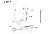
- FIG. 6 is a schematic diagram showing the configuration and operation example of the aerial image display device of the fifth embodiment.
- the optical elements forming the imaging optical system 20 are the free-form surface mirror 21 and the plane mirror 22 .
- the driving device 30 can control the movement from the first position to the second position and the movement from the second position to the first position by, for example, moving the spatial position of the plane mirror 22. Configured.
- the driving device 30 of this embodiment is configured to be able to move the plane mirror 22 to the first spatial position and the second spatial position.
- the movement of the plane mirror 22 in this embodiment is translational movement.
- the position of the display device 10 may be fixed.
- the driving device 30 may be configured to reciprocate the plane mirror 22 between the first spatial position and the second spatial position, and may be, for example, an electric slider or an electric cylinder.
- the drive device 30 may set the stationary position of the plane mirror 22 to two positions, a first spatial position and a second spatial position.
- the driving device 30 may set the rest position of the plane mirror 22 to two positions, the first spatial position and the second spatial position, and any position between the first spatial position and the second spatial position.
- the plane mirror 22 is configured to reflect the image light when the plane mirror 22 is in the first spatial position due to the translational movement.
- the image light reflected by the plane mirror 22 is reflected by the first portion 21A of the free-form surface mirror 21 .
- the display device 10 is positioned closer than the first object focus f1.
- Plane mirror 22 is configured to reflect image light when plane mirror 22 is in the second spatial position due to the translational movement.
- the image light reflected by the plane mirror 22 is reflected by the second portion 21B of the free-form surface mirror 21 .
- the display device 10 is positioned farther than the second object focus f2.
- a user of the aerial image display device 1 can visually recognize the virtual image V when the plane mirror 22 is at the first spatial position, and can visually recognize the real image R when the plane mirror 22 is at the second spatial position. can.
- the aerial image display device 1 of the present embodiment can display the real image R and the virtual image V in the air with the configuration in which the driving device 30 relatively changes the positions of the display device 10 and the optical element.
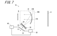
- FIG. 7 is a schematic diagram showing an example of the configuration and operation of the aerial image display device of the sixth embodiment.
- the free-form surface mirror 21 and the lens 24 are the optical elements that constitute the imaging optical system 20A.
- Lens 24 may be, for example, a convex lens, a Fresnel lens, a liquid crystal lens, or the like.
- the imaging optical system 20A of this embodiment is a catadioptric system.
- the driving device 30 can control the movement from the first position to the second position and the movement from the second position to the first position by, for example, moving the spatial position of the lens 24. Configured.
- the driving device 30 of this embodiment is configured to be able to move the lens 24 to the first spatial position and the second spatial position.
- the movement of the lens 24 in this embodiment is rotation.
- the position of the display device 10 may be fixed.
- the drive device 30 may be configured to reciprocate the lens 24 between the first spatial position and the second spatial position, and may be, for example, an electric slider or an electric cylinder.
- the drive device 30 may set the rest position of the lens 24 to two positions, a first spatial position and a second spatial position.
- the drive device 30 may set the rest position of the lens 24 to two positions, the first spatial position and the second spatial position, and any position between the first spatial position and the second spatial position.
- a user of the aerial image display device 1 can visually recognize the virtual image V when the lens 24 is at the first spatial position, and can visually recognize the real image R when the lens 24 is at the second spatial position. can.
- the aerial image display device 1 of the present embodiment can display the real image R and the virtual image V in the air with the configuration in which the driving device 30 relatively changes the positions of the display device 10 and the optical element.
- the lens 24 may be changed.
- the driving device 30 may be configured, for example, to move two lenses 24 having different lens characteristics so as to be interchanged.
- the driving device 30 can be configured to change the position at which the image light is incident on the free-form surface mirror 21 by changing the lens 24 . Accordingly, the driving device 30 can be configured to change the first position where the display device 10 is closer than the first object focus f1 and the second position where the display device 10 is farther than the second object focus f2.
- FIG. 8 is a schematic diagram showing an example of the configuration and operation of the aerial image display device of the seventh embodiment.
- the aerial image display device 1B of this embodiment is mounted on a moving body.
- the aerial image display device 1B includes a display device 10, an imaging optical system 20B, a driving device 30, a controller 40, and a camera 50.
- the position of the aerial image display device 1B is arbitrary inside and outside the moving body.
- the aerial image display device 1B may be located inside the dashboard of a mobile object.
- a "moving object" in the present disclosure may include, for example, a vehicle, a ship, an aircraft, and the like.
- Vehicles may include, for example, automobiles, industrial vehicles, rail vehicles, utility vehicles, fixed-wing aircraft that travel on runways, and the like.
- Motor vehicles may include, for example, cars, trucks, buses, motorcycles, trolleybuses, and the like.
- Industrial vehicles may include, for example, agricultural and construction industrial vehicles, and the like.
- Industrial vehicles may include, for example, forklifts, golf carts, and the like.
- Industrial vehicles for agriculture may include, for example, tractors, tillers, transplanters, binders, combines, lawn mowers, and the like.
- Industrial vehicles for construction may include, for example, bulldozers, scrapers, excavators, mobile cranes, tippers, road rollers, and the like. Vehicles may include those that are powered by humans. Vehicle classification is not limited to the above example. For example, automobiles may include road-drivable industrial vehicles. Multiple classifications may contain the same vehicle. Vessels may include, for example, marine jets, boats, tankers, and the like. Aircraft may include, for example, fixed-wing aircraft, rotary-wing aircraft, and the like. An example in which the mobile body includes the windshield 25 will be described below. The vehicle may be any of the above examples, provided it has a combiner in place of the windshield 25 .
- the camera 50 is attached to a mobile object.
- the camera 50 is configured to capture an image of a space where the face or upper body of the user who is the driver of the mobile object is supposed to exist.
- the mounting position of the camera 50 is arbitrary inside and outside the moving body.
- the camera 50 may be located in or on the dashboard of the mobile.
- camera 50 may be located in other devices such as air ducts.
- the camera 50 may be an infrared camera configured to receive infrared light and generate an image. Camera 50 may have the functions of both an infrared light camera and a visible light camera.
- the camera 50 may include, for example, a CCD (Charge Coupled Device) or CMOS (Complementary Metal Oxide Semiconductor) image sensor.
- the camera 50 is configured to output captured images to the controller 40 .
- the camera 50 may be configured to output captured images to the controller 40 via wired communication or wireless communication. Wired communication can include CAN (Controller Area Network), for example.
- the controller 40 may be configured to detect the position of the user's eye 5 based on the captured image output from the camera 50 .
- the controller 40 changes the image displayed on the display device 10 according to the detected position of the user's eye 5 .
- the free-form surface mirror 21 and the windshield 25 are the optical elements that constitute the imaging optical system 20B.
- Image light emitted from the display device 10 is reflected by the free-form surface mirror (concave mirror) 21 , reaches the windshield 25 , is reflected by the windshield 25 , and reaches the eye 5 of the user.
- the user can visually recognize the aerial image.
- the driving device 30 can control the movement from the first position to the second position and the movement from the second position to the first position, for example, by moving the spatial position of the display device 10. configured to
- the drive device 30 of this embodiment is configured to be able to move the display device 10 to the first spatial position and the second spatial position.
- the movement of the display device 10 in this embodiment is rotation.
- the position of the free-form surface mirror 21 may be fixed.
- the drive device 30 may be configured to reciprocate the display device 10 between the first spatial position and the second spatial position, and may be, for example, an electric slider or an electric cylinder.
- the driving device 30 may set the rest position of the display device 10 to two positions, a first spatial position and a second spatial position.
- the driving device 30 may set the rest position of the display device 10 to two positions, the first spatial position and the second spatial position, and any position between the first spatial position and the second spatial position.
- the free-form surface mirror 21 When the display device 10 is in the first spatial position by rotation, the free-form surface mirror 21 is configured to reflect the image light on the first portion 21A.
- the windshield 25 is configured to reflect the image light reflected by the first portion 21A. At this time, the display device 10 is positioned closer than the first object focus f1.
- the free-form surface mirror 21 is configured to reflect the image light at the second portion 21B when the display device 10 is in the second spatial position by rotation.
- the windshield 25 is configured to reflect the image light reflected by the second portion 21B. At this time, the display device 10 is positioned farther than the second object focus f2.
- the user of the aerial image display device 1 can visually recognize the virtual image V by the image light reflected by the windshield 25, and the display device 10 is positioned in the second space.
- the image light reflected by the windshield 25 allows the real image R to be visually recognized.
- the aerial image display device 1B of the present embodiment is configured such that the driving device 30 relatively changes the positions of the display device 10 and the optical element, so that the real image R and the virtual image V can be displayed in midair.
- the controller 40 may control the driving device 30 according to the position of the user's eye 5, for example.
- the controller 40 may move the display device 10 according to the position of the user's eye 5 to switch the display between the real image R and the virtual image V in the air.
- the controller 40 may control the driving device 30 according to, for example, the operating state of the mobile object (such as when the vehicle is stopped or when the vehicle is running).
- the controller 40 may move the display device 10 according to the operating state of the moving body to switch between the aerial display of the real image R and the virtual image V.
- the display device 10 is fixed, the position of the free-form surface mirror 21 is changed between the first position and the second position, and the aerial display of the real image R and the virtual image V is switched. good.
- the controller 40 may cause the display device 10 to display a black image, for example. By displaying a black image, deterioration of visibility can be reduced, and discomfort can be reduced.
- the aerial image display device 1B may be the following other embodiments.
- the camera 50 photographs the user so as to obtain an image of the pupil of the user's eye 5, and the controller 40 controls to enlarge the image displayed on the display device 10 when the pupil changes to become larger. you can go If the user's pupils change to dilate, the user is gazing at the image or part of the image. At this time, by enlarging the image displayed on the display device 10, the user can easily view the image or part of the image. As a result, for example, when the user is riding in a vehicle, it becomes easier for the user to avoid danger.
- the magnification of the image may be more than 1 and about 3 or less, but is not limited to this range. Also, by detecting which part of the image the user is gazing at, only a part of the image that the user is gazing at may be enlarged.
- the camera 50 photographs the user so as to obtain an image of the pupil of the user's eye 5, and the controller 40 increases the brightness of the image displayed on the display device 10 when the pupil changes to become larger. may be controlled. In this case as well, the same effect as described above is obtained, and if the user is riding in a vehicle, for example, it becomes easier for the user to avoid danger.
- the improvement rate of the brightness of the image may be more than 1 times and about 10 times or less, it is not limited to this range. Also, by detecting which part of the image the user is gazing at, the luminance of only a part of the image that the user is gazing at may be improved.
- the camera 50 photographs the user so as to obtain an image of the pupil of the user's eye 5, and the controller 40 improves the contrast of the image displayed on the display device 10 when the pupil changes to become larger. may be controlled. In this case as well, the same effect as described above is obtained, and if the user is riding in a vehicle, for example, it becomes easier for the user to avoid danger.
- the improvement rate of image contrast may be more than 1 times and about 2 times or less, but is not limited to this range. Also, by detecting which part of the image the user is gazing at, the contrast of only a part of the image that the user is gazing at may be improved.
- the camera 50 photographs the user so as to obtain an image of the pupil of the user's eye 5, and the controller 40 increases the frame frequency of the image displayed on the display device 10 when the pupil changes to become larger. You may perform control to let you do it. In this case as well, the same effect as described above is obtained, and if the user is riding in a vehicle, for example, it becomes easier for the user to avoid danger.
- the improvement rate of the frame frequency of the image may be more than 1 times and about 8 times or less, but is not limited to this range.
- Descriptions such as “first” and “second” in this disclosure are identifiers for distinguishing the configurations. Configurations that are differentiated in descriptions such as “first” and “second” in this disclosure may interchange the numbers in that configuration. For example, a first reflective element can interchange identifiers “first” and “second” with a second reflective element. The exchange of identifiers is done simultaneously. The configurations are still distinct after the exchange of identifiers. Identifiers may be deleted. Configurations from which identifiers have been deleted are distinguished by codes. The description of identifiers such as “first” and “second” in this disclosure should not be used as a basis for interpreting the order of the configuration or the existence of lower numbered identifiers.
- a display device that displays an image propagating as image light
- an imaging optical system that uses the image light as incident light, is configured by at least one optical element, and has a first object focus and a second object focus that is closer in focal length than the first object focus
- a driving device that relatively changes the positional relationship between the first object focus and the second object focus and the display device;
- the driving device a first position where the display device is located closer to the first object focus and a virtual image is displayed in the air
- An aerial image display device configured to be able to change a second position in which the display device is positioned farther than the second object focus and a real image is displayed in the air.
- the aerial image display device is a free-form mirror
- the aerial image display device wherein the imaging optical system is configured to be able to change the first object focus and the second object focus depending on the incident position of the image light incident on the free-form surface mirror.
- An aerial image display device further comprising a controller that changes an image to be displayed on the display device.
- the aerial image display device controls an image displayed on the display device when a virtual image is displayed in the air to be enlarged with respect to an image displayed on the display device when a real image is displayed in the air. display device.
- the aerial image display device controls the brightness of the image displayed on the display device when the virtual image is displayed in the air to be higher than the brightness of the image displayed on the display device when the real image is displayed in the air.
- Aerial image display device controls the brightness of the image displayed on the display device when the virtual image is displayed in the air to be higher than the brightness of the image displayed on the display device when the real image is displayed in the air.
- the aerial image display device controls the contrast of the image displayed on the display device when a virtual image is displayed in the air to be higher than the contrast of the image displayed on the display device when a real image is displayed in the air.
- Aerial image display device controls the contrast of the image displayed on the display device when a virtual image is displayed in the air to be higher than the contrast of the image displayed on the display device when a real image is displayed in the air.
- the aerial image display device controls the frame frequency of the image displayed on the display device when the virtual image is displayed in the air to be higher than the frame frequency of the image displayed on the display device when the real image is displayed in the air.
- Aerial image display device controls the frame frequency of the image displayed on the display device when the virtual image is displayed in the air to be higher than the frame frequency of the image displayed on the display device when the real image is displayed in the air.
- the aerial image display device according to (11) or (12) above, the camera photographs the user to obtain an image of the pupil of the user's eye;
- the aerial image display device according to any one of (11) to (13) above, the camera photographs the user to obtain an image of the pupil of the user's eye;
- the aerial image display device according to any one of (11) to (14) above, the camera photographs the user to obtain an image of the pupil of the user's eye;
- aerial display of a real image and a virtual image is possible.
- Reference Signs List 1 1A, 1B aerial image display device 5 eye 10 display device 20, 20A, 20B imaging optical system 21 free-form surface mirror 21A first portion 21B second portion 22 plane mirror 24 lens 25 windshield 30 drive device 40 controller 50 camera R Real image V Virtual image f1 1st object focus f2 2nd object focus
Landscapes
- Physics & Mathematics (AREA)
- General Physics & Mathematics (AREA)
- Optics & Photonics (AREA)
Priority Applications (3)
| Application Number | Priority Date | Filing Date | Title |
|---|---|---|---|
| JP2023542339A JP7642833B2 (ja) | 2021-08-20 | 2022-08-05 | 空中像表示装置 |
| EP22858346.4A EP4390514A4 (en) | 2021-08-20 | 2022-08-05 | Aerial image display device |
| US18/683,673 US20240345413A1 (en) | 2021-08-20 | 2022-08-05 | Aerial image display device |
Applications Claiming Priority (2)
| Application Number | Priority Date | Filing Date | Title |
|---|---|---|---|
| JP2021135176 | 2021-08-20 | ||
| JP2021-135176 | 2021-08-20 |
Publications (1)
| Publication Number | Publication Date |
|---|---|
| WO2023022025A1 true WO2023022025A1 (ja) | 2023-02-23 |
Family
ID=85239514
Family Applications (1)
| Application Number | Title | Priority Date | Filing Date |
|---|---|---|---|
| PCT/JP2022/030113 Ceased WO2023022025A1 (ja) | 2021-08-20 | 2022-08-05 | 空中像表示装置 |
Country Status (4)
| Country | Link |
|---|---|
| US (1) | US20240345413A1 (https=) |
| EP (1) | EP4390514A4 (https=) |
| JP (1) | JP7642833B2 (https=) |
| WO (1) | WO2023022025A1 (https=) |
Cited By (1)
| Publication number | Priority date | Publication date | Assignee | Title |
|---|---|---|---|---|
| WO2025142540A1 (ja) * | 2023-12-27 | 2025-07-03 | 日本精機株式会社 | 表示制御装置、表示装置、及び表示制御方法 |
Citations (5)
| Publication number | Priority date | Publication date | Assignee | Title |
|---|---|---|---|---|
| JPH0457430U (https=) * | 1990-09-26 | 1992-05-18 | ||
| KR20020084470A (ko) * | 2001-05-02 | 2002-11-09 | 대한민국(서울대학교 총장) | 입체 영상 표시 장치 |
| JP2010164941A (ja) * | 2008-10-30 | 2010-07-29 | Honda Motor Co Ltd | 車両用表示装置 |
| JP2011070073A (ja) * | 2009-09-28 | 2011-04-07 | Stanley Electric Co Ltd | 表示装置 |
| JP2011253128A (ja) | 2010-06-03 | 2011-12-15 | Nippon Seiki Co Ltd | 結像装置 |
Family Cites Families (2)
| Publication number | Priority date | Publication date | Assignee | Title |
|---|---|---|---|---|
| JP2008287190A (ja) * | 2007-05-21 | 2008-11-27 | Denso Corp | 表示装置 |
| JP2011093413A (ja) * | 2009-10-29 | 2011-05-12 | Nippon Seiki Co Ltd | 車両用表示装置 |
-
2022
- 2022-08-05 US US18/683,673 patent/US20240345413A1/en active Pending
- 2022-08-05 EP EP22858346.4A patent/EP4390514A4/en active Pending
- 2022-08-05 WO PCT/JP2022/030113 patent/WO2023022025A1/ja not_active Ceased
- 2022-08-05 JP JP2023542339A patent/JP7642833B2/ja active Active
Patent Citations (5)
| Publication number | Priority date | Publication date | Assignee | Title |
|---|---|---|---|---|
| JPH0457430U (https=) * | 1990-09-26 | 1992-05-18 | ||
| KR20020084470A (ko) * | 2001-05-02 | 2002-11-09 | 대한민국(서울대학교 총장) | 입체 영상 표시 장치 |
| JP2010164941A (ja) * | 2008-10-30 | 2010-07-29 | Honda Motor Co Ltd | 車両用表示装置 |
| JP2011070073A (ja) * | 2009-09-28 | 2011-04-07 | Stanley Electric Co Ltd | 表示装置 |
| JP2011253128A (ja) | 2010-06-03 | 2011-12-15 | Nippon Seiki Co Ltd | 結像装置 |
Non-Patent Citations (1)
| Title |
|---|
| See also references of EP4390514A4 |
Cited By (1)
| Publication number | Priority date | Publication date | Assignee | Title |
|---|---|---|---|---|
| WO2025142540A1 (ja) * | 2023-12-27 | 2025-07-03 | 日本精機株式会社 | 表示制御装置、表示装置、及び表示制御方法 |
Also Published As
| Publication number | Publication date |
|---|---|
| JP7642833B2 (ja) | 2025-03-10 |
| EP4390514A1 (en) | 2024-06-26 |
| JPWO2023022025A1 (https=) | 2023-02-23 |
| EP4390514A4 (en) | 2025-08-06 |
| US20240345413A1 (en) | 2024-10-17 |
Similar Documents
| Publication | Publication Date | Title |
|---|---|---|
| JP6516223B2 (ja) | 表示装置 | |
| US9678340B2 (en) | Vehicular display apparatus | |
| CN113165513A (zh) | 平视显示器、车辆用显示系统以及车辆用显示方法 | |
| KR102192933B1 (ko) | 허상 표시 장치, 중간상 형성부 및 화상 표시광 생성 유닛 | |
| US12382185B2 (en) | Vehicular display system and image irradiation device | |
| JP7642832B2 (ja) | 空中像表示装置 | |
| WO2019009240A1 (ja) | 画像投影装置及び移動体 | |
| WO2017061016A1 (ja) | 情報表示装置 | |
| JP7332747B2 (ja) | 表示装置および移動体 | |
| JP7642833B2 (ja) | 空中像表示装置 | |
| US20230152586A1 (en) | Image generation device and head-up display | |
| JP2017015805A (ja) | 虚像表示装置 | |
| JPWO2018043210A1 (ja) | 光学部材、光学部材の製造方法及び画像表示システム | |
| WO2023022023A1 (ja) | 空中像表示装置 | |
| US12061335B2 (en) | Vehicular head-up display and light source unit used therefor | |
| JP7379760B1 (ja) | 空中像表示装置 | |
| WO2018186149A1 (ja) | ヘッドアップディスプレイシステム、およびヘッドアップディスプレイシステムを備える移動体 | |
| WO2023228920A1 (ja) | 空中像表示装置 | |
| JP7274392B2 (ja) | カメラ、ヘッドアップディスプレイシステム、及び移動体 | |
| CN115461671A (zh) | 图像显示系统 | |
| JP7495584B1 (ja) | 虚像表示装置、移動体、虚像表示装置の駆動方法、及びプログラム | |
| CN112889275A (zh) | 通信平视显示器系统、通信设备、移动体以及程序 | |
| CN112955933A (zh) | 控制器、位置判定装置、位置判定系统、显示系统、程序以及记录介质 | |
| JP2019159207A (ja) | 情報表示装置 | |
| WO2018030203A1 (ja) | 表示装置 |
Legal Events
| Date | Code | Title | Description |
|---|---|---|---|
| 121 | Ep: the epo has been informed by wipo that ep was designated in this application |
Ref document number: 22858346 Country of ref document: EP Kind code of ref document: A1 |
|
| WWE | Wipo information: entry into national phase |
Ref document number: 2023542339 Country of ref document: JP |
|
| WWE | Wipo information: entry into national phase |
Ref document number: 18683673 Country of ref document: US |
|
| WWE | Wipo information: entry into national phase |
Ref document number: 2022858346 Country of ref document: EP |
|
| NENP | Non-entry into the national phase |
Ref country code: DE |
|
| ENP | Entry into the national phase |
Ref document number: 2022858346 Country of ref document: EP Effective date: 20240320 |