WO2023022007A1 - 磁気変調ギヤ及びギヤモータ - Google Patents
磁気変調ギヤ及びギヤモータ Download PDFInfo
- Publication number
- WO2023022007A1 WO2023022007A1 PCT/JP2022/029944 JP2022029944W WO2023022007A1 WO 2023022007 A1 WO2023022007 A1 WO 2023022007A1 JP 2022029944 W JP2022029944 W JP 2022029944W WO 2023022007 A1 WO2023022007 A1 WO 2023022007A1
- Authority
- WO
- WIPO (PCT)
- Prior art keywords
- magnetic
- conductive portion
- pole
- gear
- modulation gear
- Prior art date
Links
- 230000005291 magnetic effect Effects 0.000 title claims abstract description 164
- 239000004020 conductor Substances 0.000 claims description 61
- 230000002093 peripheral effect Effects 0.000 claims description 30
- 230000009467 reduction Effects 0.000 abstract description 13
- 230000004048 modification Effects 0.000 description 39
- 238000012986 modification Methods 0.000 description 39
- 230000004907 flux Effects 0.000 description 21
- 230000005389 magnetism Effects 0.000 description 11
- 238000010586 diagram Methods 0.000 description 8
- 230000007423 decrease Effects 0.000 description 6
- 229910000831 Steel Inorganic materials 0.000 description 5
- 230000005307 ferromagnetism Effects 0.000 description 5
- 229910001220 stainless steel Inorganic materials 0.000 description 5
- 239000010935 stainless steel Substances 0.000 description 5
- 239000010959 steel Substances 0.000 description 5
- XEEYBQQBJWHFJM-UHFFFAOYSA-N Iron Chemical compound [Fe] XEEYBQQBJWHFJM-UHFFFAOYSA-N 0.000 description 4
- 229910052782 aluminium Inorganic materials 0.000 description 4
- 230000005540 biological transmission Effects 0.000 description 4
- 230000000694 effects Effects 0.000 description 4
- 239000000696 magnetic material Substances 0.000 description 4
- RYGMFSIKBFXOCR-UHFFFAOYSA-N Copper Chemical compound [Cu] RYGMFSIKBFXOCR-UHFFFAOYSA-N 0.000 description 3
- RTAQQCXQSZGOHL-UHFFFAOYSA-N Titanium Chemical compound [Ti] RTAQQCXQSZGOHL-UHFFFAOYSA-N 0.000 description 3
- XAGFODPZIPBFFR-UHFFFAOYSA-N aluminium Chemical compound [Al] XAGFODPZIPBFFR-UHFFFAOYSA-N 0.000 description 3
- 230000004323 axial length Effects 0.000 description 3
- 239000010949 copper Substances 0.000 description 3
- 229910052802 copper Inorganic materials 0.000 description 3
- 229910001172 neodymium magnet Inorganic materials 0.000 description 3
- 239000010936 titanium Substances 0.000 description 3
- 229910052719 titanium Inorganic materials 0.000 description 3
- 229910000576 Laminated steel Inorganic materials 0.000 description 2
- 230000008878 coupling Effects 0.000 description 2
- 238000010168 coupling process Methods 0.000 description 2
- 238000005859 coupling reaction Methods 0.000 description 2
- 230000005294 ferromagnetic effect Effects 0.000 description 2
- 239000012212 insulator Substances 0.000 description 2
- 230000003993 interaction Effects 0.000 description 2
- 229910052742 iron Inorganic materials 0.000 description 2
- 238000012423 maintenance Methods 0.000 description 2
- 239000000463 material Substances 0.000 description 2
- 238000010248 power generation Methods 0.000 description 2
- 239000011347 resin Substances 0.000 description 2
- 229920005989 resin Polymers 0.000 description 2
- 238000005096 rolling process Methods 0.000 description 2
- 230000001133 acceleration Effects 0.000 description 1
- 230000008859 change Effects 0.000 description 1
- 238000004140 cleaning Methods 0.000 description 1
- 239000004519 grease Substances 0.000 description 1
- 238000004519 manufacturing process Methods 0.000 description 1
- 238000005259 measurement Methods 0.000 description 1
- 238000000034 method Methods 0.000 description 1
- 239000000843 powder Substances 0.000 description 1
- 230000003014 reinforcing effect Effects 0.000 description 1
- 239000004065 semiconductor Substances 0.000 description 1
- 238000004804 winding Methods 0.000 description 1
Images


Classifications
-
- F—MECHANICAL ENGINEERING; LIGHTING; HEATING; WEAPONS; BLASTING
- F16—ENGINEERING ELEMENTS AND UNITS; GENERAL MEASURES FOR PRODUCING AND MAINTAINING EFFECTIVE FUNCTIONING OF MACHINES OR INSTALLATIONS; THERMAL INSULATION IN GENERAL
- F16H—GEARING
- F16H49/00—Other gearings
-
- H—ELECTRICITY
- H02—GENERATION; CONVERSION OR DISTRIBUTION OF ELECTRIC POWER
- H02K—DYNAMO-ELECTRIC MACHINES
- H02K7/00—Arrangements for handling mechanical energy structurally associated with dynamo-electric machines, e.g. structural association with mechanical driving motors or auxiliary dynamo-electric machines
- H02K7/10—Structural association with clutches, brakes, gears, pulleys or mechanical starters
Definitions
- the present invention relates to magnetic modulation gears and gear motors.
- Patent Document 1 a plurality of outer pole magnets arranged in the circumferential direction, a plurality of inner pole magnets arranged in the circumferential direction radially inward of the outer pole magnet, the outer pole magnet and the inner pole magnet
- a magnetic modulation gear is shown comprising a plurality of pole pieces circumferentially arranged between and. A plurality of pole pieces are held in a non-magnetic pole holder integral with the shaft.
- An object of the present invention is to provide a magnetically modulated gear and a gear motor that can suppress reduction in torque and efficiency caused by eddy currents.
- a magnetic modulation gear includes: a plurality of outer pole pieces arranged in the circumferential direction; a plurality of magnetic pole pieces arranged in the circumferential direction radially inward of the plurality of outer pole magnets; and a plurality of magnetic pole pieces radially arranged inward of the plurality of magnetic pole pieces.
- a magnetic modulation gear comprising a plurality of inner pole magnets arranged in a circumferential direction, further comprising a shaft member coupled with the plurality of pole pieces; the shaft member includes a non-conductive portion and a conductive portion; The conductive portion is coupled to the plurality of pole pieces via the non-conductive portion.
- Another aspect of the magnetic modulation gear according to the present invention includes: a plurality of outer pole pieces arranged in the circumferential direction; a plurality of magnetic pole pieces arranged in the circumferential direction radially inward of the plurality of outer pole magnets; and a plurality of magnetic pole pieces radially arranged inward of the plurality of magnetic pole pieces.
- a magnetic modulation gear comprising a plurality of inner pole magnets arranged in a circumferential direction, A conductor is provided in a region between the inner peripheral end of the plurality of outer pole magnets and the outer peripheral end of the plurality of inner pole magnets in the radial direction and the distance from the magnetic pole piece in the axial direction is less than 3 mm. do not have.
- a gear motor according to the present invention; an electric motor; the magnetic modulation gear receiving power from the electric motor; Prepare.
- FIG. 10 is a diagram showing a modification 7 including other conductive parts;
- FIG. 10 is a diagram showing a modified example 8 including other conductive parts;
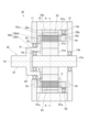
- FIG. 1 is a cross-sectional view showing a magnetic modulation gear according to an embodiment of the invention.
- 2 is a perspective view showing a cross section of the magnetic modulation gear of FIG. 1.
- FIG. The cross section of FIG. 2 shows the section taken along line AA of FIG.
- the direction along the central axis Ax is called the axial direction
- the direction perpendicular to the central axis Ax is called the radial direction
- the direction of rotation about the central axis Ax is called the circumferential direction.
- the side where the shaft member 32b protrudes in the axial direction left side in the drawing
- the opposite side right side in the drawing
- the magnetic modulation gear 30 includes a high speed rotor 31, a low speed rotor 32, a plurality of outer pole magnets 33, a casing 10, a load side cover 11 and an anti-load side cover 12.
- the high-speed rotor 31 has a shaft 21a, a rotor yoke 31b and a plurality of inner pole magnets 31a. Both axial end portions of the shaft 21a extend from the rotor yoke 31b, and these end portions are supported by bearings 13a and 13b.
- the plurality of inner pole magnets 31a are permanent magnets such as neodymium magnets, and are arranged in the circumferential direction such that their polar directions are alternately different, and are attached to the outer peripheral surface of the rotor yoke 31b. Also, the plurality of inner pole magnets 31a may be integrated in a ring shape, or may be individually divided.
- the low-speed rotor 32 is stepped and hollow on the side opposite to the load, and is arranged concentrically with the high-speed rotor 31 .
- the low-speed rotor 32 has a plurality of magnetic pole pieces (pole pieces) 32a arranged on the outer diameter side of the inner pole magnet 31a.
- the magnetic pole pieces 32a are made of laminated steel plates.
- the plurality of magnetic pole pieces 32a are arranged at predetermined intervals in the circumferential direction.
- the number of magnetic pole pieces 32a is the number of outer pole pairs (the number of pole pairs of outer pole magnet 33) ⁇ the number of inner pole pairs (the number of pole pairs of inner pole magnet 31a), generally the number of outer pole pairs+the number of inner pole pairs.
- Two magnetic pole pieces 32a adjacent to each other in the circumferential direction may be connected by a thin connecting portion, or may be connected via a non-magnetic material.
- the low speed rotor 32 further has a shaft member 32b located on the load side of the pole pieces 32a.
- the shaft member 32b has a conductive portion 32b1 and a non-conductive portion 32b2, the conductive portion 32b1 being coupled to the plurality of pole pieces 32a via the non-conductive portion 32b2.
- the conductive portion 32b1 is a conductor having no magnetism (ferromagnetism) such as stainless steel, aluminum, titanium, or copper, but may be a conductor having magnetism (ferromagnetism) such as steel.
- the non-conductive portion 32b2 is made of a material (a non-magnetic material and an insulator) that does not have magnetism and conductivity.
- the non-conductive portion 32b2 may be made of resin.
- the low-speed rotor 32 further has an extension portion 32c extending from the magnetic pole piece 32a to the anti-load side, and a ring member 32g attached to the outer peripheral portion of the extension portion 32c.
- the ring member 32g is a conductor having no magnetism (ferromagnetism) such as stainless steel, aluminum, titanium, or copper, but may be a conductor having magnetism (ferromagnetism) such as steel.
- the extending portion 32c is made of a material (non-magnetic material and insulator) that does not have magnetism and conductivity.
- the extending portion 32c may be made of resin.
- the conductive portion 32b1 and the non-conductive portion 32b2 of the shaft member 32b, and the ring member 32g have a shape in which the cross section of FIG. may
- the shaft member 32b (the conductive portion 32b1 and the non-conductive portion 32b2) of the low-speed rotor 32, the plurality of magnetic pole pieces 32a, the extension portion 32c on the anti-load side, and the ring member 32g are integrated to form a low-speed rotor.
- the rotor 32 rotates integrally.
- a portion of the load side of the shaft member 32b is exposed to the outside from the load side cover 11, and is connected to a driven member (not shown).
- the plurality of outer pole magnets 33 are concentrically arranged with a predetermined gap on the outer diameter side of the plurality of magnetic pole pieces 32a.
- the plurality of outer pole magnets 33 may be permanent magnets such as neodymium magnets, or may be electromagnets.
- the multiple outer pole magnets 33 have a larger number of poles than the multiple inner pole magnets 31a.
- the plurality of outer pole magnets 33 are arranged in the circumferential direction such that the directions of polarities alternately differ, and are attached to the inner peripheral surface of the casing 10 via yoke portions 33a (not shown in FIG. 2).
- a plurality of outer pole magnets 33 function as a stator.
- the plurality of outer pole magnets 33 may be integrated in a ring shape, or may be individually divided.
- the axial lengths of the plurality of outer pole magnets 33, the axial lengths of the plurality of magnetic pole pieces 32a, and the axial lengths of the plurality of inner pole magnets 31a substantially match each other.
- the magnet 33, the plurality of magnetic pole pieces 32a and the plurality of inner pole magnets 31a are arranged so as to substantially overlap.
- the casing 10 radially outwardly covers the plurality of outer pole magnets 33, the plurality of magnetic pole pieces 32a, and the plurality of inner pole magnets 31a.
- the load side cover 11 is connected to the casing 10 and covers the load side of the plurality of outer pole magnets 33, the plurality of magnetic pole pieces 32a and the plurality of inner pole magnets 31a.
- the anti-load side cover 12 is connected to the casing 10 and covers the anti-load sides of the plurality of outer pole magnets 33, the plurality of magnetic pole pieces 32a and the plurality of inner pole magnets 31a.
- the magnetic modulation gear 30 further includes bearings 13a, 13b that rotatably support the high-speed rotor 31, and bearings 13a, 13c, 13d that rotatably support the low-speed rotor 32.
- the bearings 13a to 13d are ball bearings, but various types of bearings such as roller bearings and tapered roller bearings may be applied.
- the bearing 13 a is fitted between the low-speed rotor 32 and the high-speed rotor 31 and supports the high-speed rotor 31 rotatably with respect to the low-speed rotor 32 .
- the bearing 13 a supports the low speed rotor 32 rotatably with respect to the high speed rotor 31 .
- the bearing 13b is fitted between the anti-load side cover 12 and the high speed rotor 31 (its shaft 21a).
- the bearing 13c is fitted between the load side cover 11 and the low speed rotor 32 (its shaft member 32b).
- the bearing 13d is fitted between the casing 10 and the low speed rotor 32 (its ring member 32g).
- Each of the bearings 13a-13d has an outer ring, an inner ring and rolling elements.
- the outer ring, inner ring and rolling elements are made of steel or the like, and have electrical conductivity and magnetism (ferromagnetism).
- the magnetic modulation gear 30 performs deceleration operation in which the rotational motion input to the high-speed rotor 31 is decelerated and output from the low-speed rotor 32 , and acceleration operation in which the rotational motion input to the low-speed rotor 32 is accelerated and output from the high-speed rotor 31 . High speed operation is possible.
- the plurality of inner pole magnets 31a included in the high-speed rotor 31 rotate around the central axis Ax. Then, the rotating magnetic flux of the inner pole magnet 31a passes through the plurality of magnetic pole pieces 32a, so that the outer magnetic flux is generated radially outward of the plurality of magnetic pole pieces 32a (the gap between the magnetic pole piece 32a and the outer pole magnet 33). It is modulated into a spatial magnetic flux containing waveform components with the same wave number as the number of pole pairs of the pole magnet 33 .
- the gear ratio (reduction ratio) at this time is (the number of magnetic pole pieces 32a/the number of pole pairs of the inner pole magnet 31a).
- the plurality of magnetic pole pieces 32a of the low-speed rotor 32 rotate around the central axis Ax while drawing the magnetic flux of the plurality of outer pole magnets 33 .
- the magnetic flux of the outer pole magnet 33 generates a waveform component with the same wave number as the number of pole pairs of the inner pole magnet 31a in the radially inner side of the plurality of magnetic pole pieces 32a (the gap between the magnetic pole piece 32a and the inner pole magnet 31a).
- the gear ratio (speed increase ratio) at this time is (the number of pole pairs of the inner pole magnet 31a/the number of the magnetic pole pieces 32a).
- FIG. 1 shows a structure in which the outer pole magnets 33 are fixed, the low-speed rotor 32 having a plurality of magnetic pole pieces 32a is fixed, while the plurality of outer pole magnets 33 are rotatably supported to reduce speed.
- a configuration may be employed in which the resulting rotational motion is output via a plurality of outer pole magnets 33 . Even in this case, the low-speed rotor 32 rotates relatively to the plurality of outer pole magnets 33 and rotates relatively to the high-speed rotor 31 .
- Figures 3A and 3B are graphs showing changes in properties due to the arrangement of conductors, with Figure 3A showing eddy current loss properties and Figure 3B showing efficiency properties.
- 4A and 4B are diagrams showing analysis conditions for characteristics, showing a first arrangement and a second arrangement of conductors 51, respectively.
- the graph lines of the first arrangement and the graph lines of the second arrangement have the radial arrangement of the conductors 51 as shown in FIGS. 4A and 4B, respectively, and the axial distance L is changed.
- FIGS. 4A and 4B show a part of the cross section (above the central axis Ax) of the inner pole magnet 31a, the magnetic pole piece 32a, and the optional conductor 51 taken along a vertical plane including the central axis Ax.
- a magnetic flux H passes between the inner pole magnet 31a and the magnetic pole piece 32a.
- the conductor 51 having no magnetism an annular aluminum centered on the central axis Ax was used.
- the magnetic flux leaking from between the inner pole magnet 31a and the magnetic pole piece 32a may enter the conductor 51 depending on the arrangement.
- the loss reduces the transmission torque density and efficiency of the magnetic modulation gear 30 .
- the region Rx1 corresponds to a region from the outer peripheral end E1 of the inner pole magnet 31a to the inner peripheral end of the outer pole magnet 33 in the radial direction, as shown in FIGS. 4A and 4B.
- the region Rx2 corresponds to a region radially inward of the outer peripheral end E1 of the inner pole magnet 31a.
- the characteristics shown in the graphs of FIGS. 3A and 3B similarly appear when the conductor 51 is positioned near the outer pole magnet 33 and the pole piece 32a. That is, when the conductor 51 overlaps the region Rx1 and the region outside the inner peripheral end of the outer pole magnet 33 in the radial direction and is close to the pole piece 32a in the axial direction, the loss due to the eddy current Ic is increases, and torque and efficiency are greatly reduced. In addition, when the conductor 51 is arranged in the region outside the inner peripheral end of the outer pole magnet 33 in the radial direction, even if the conductor 51 and the magnetic pole piece 32a are close in the axial direction, the torque and efficiency will be reduced. decline is suppressed.
- the conductor 51 is magnetic (ferromagnetic), such as when the conductor 51 is made of steel, the magnetic pole piece 32a and the inner pole magnet 31a (or the outer pole magnet 33) are further pulled in by the conductor 51 by attracting fluctuating magnetic flux.
- the magnetic flux density in the gap between is lowered, and the transmission torque tightness and efficiency of the magnetic modulation gear 30 are further lowered.
- iron loss eddy current loss and hysteresis loss
- the conductor 51 arranged near the pole piece 32a is non-magnetic and the main loss is due to the eddy current Ic.
- the magnetic modulation gear 30 of the present embodiment has the following conductor arrangement structures 1 to 3 in order to suppress a decrease in torque and efficiency.
- the magnetic modulation gear 30 has no conductors in the region R1a, as shown in FIG. In other words, the conductive parts are arranged outside the region R1a.
- the magnetic modulation gear 30 may be configured without conductors in the region R1. In other words, the electrically conductive component may be considered to be arranged outside the region R1a.
- the region R1a is a region between the inner peripheral ends of the plurality of outer pole magnets 33 and the outer peripheral ends of the plurality of inner pole magnets 31a in the radial direction, and the distance from the magnetic pole piece 32a in the axial direction is X mm.
- Equivalent to. Xmm is preferably 8mm, more preferably 3mm.
- the region R1 is defined by the inner peripheral ends of the plurality of outer pole magnets 33 and the plurality of inner pole magnets 33 in the radial direction inside the members (the casing 10, the load side cover 11, and the anti-load side cover 12) that cover the outside of the magnetic modulation gear 30. It corresponds to the area between the outer peripheral edge of the pole magnet 31a.
- the above conductors or conductive parts are parts made of non-magnetic conductors such as stainless steel, aluminum, titanium, copper, etc., but magnetic (ferromagnetic) conductors such as iron may be a part made of
- the parts include the conductive portion 32b1 of the shaft member 32b, the ring member 32g, a sensor including a conductor, a stay of the sensor, a fastening member such as a bolt, and the like.
- the component may also include bearings 13a-13d.
- a conductive portion 32b1 of the shaft member 32b is coupled to the pole piece 32a via a non-conductive portion 32b2.
- a connecting portion between the conductive portion 32b1 and the non-conductive portion 32b2 is arranged so as not to overlap the region R1 or the region R1a.
- the conductive portion 32b1 is located in a region radially outward of the inner peripheral ends of the plurality of outer pole magnets 33, a region radially inward of the outer peripheral ends of the plurality of inner pole magnets 31a, and the magnetic pole piece 32a. It is arranged within the area including the area where the axial distance is X mm or more.
- a conductive component (for example, a ring member 32g) connected to the low-speed rotor 32 is arranged outside the region R1 or the region R1a.
- the above-mentioned component (for example, the ring member 32g) is arranged in a region radially outward of the inner peripheral ends of the plurality of outer pole magnets 33 and a region radially inward of the outer peripheral ends of the plurality of inner pole magnets 31a. It is arranged within a region that is the sum of the region and the region where the axial distance from the pole piece 32a is X mm or more.
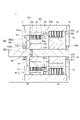
- FIG. 5 is a cross-sectional view showing a gear motor according to an embodiment of the invention.
- the gear motor 1 of this embodiment includes a motor (electric motor) 20 that outputs rotational power, a magnetic modulation gear 30 that receives the rotational power of the motor 20, a casing 10 that houses the motor 20 and the magnetic modulation gear 30, and a load side cover. 11 and an anti-load side cover 12 .
- the motor 20 includes a motor rotor 21 and a motor stator 22 .
- the magnetic modulation gear 30 includes a high-speed rotor 31, a low-speed rotor 32, and a plurality of outer pole magnets 33, as described above.
- the rotating shaft of the motor 20 and the rotating shaft of the magnetic modulation gear 30 overlap on the central axis Ax.
- the motor 20 and the magnetic modulation gear 30 are arranged side by side in the axial direction.
- the motor rotor 21 has a shaft 21a, a rotor yoke 21b, and a rotor magnet 21c.
- the rotor yoke 21b is made of a magnetic material and fixed to the outer peripheral surface of the shaft 21a.
- the rotor magnet 21c is a permanent magnet such as a neodymium magnet, and a plurality of magnets corresponding to a predetermined number of poles are attached to a portion of the outer peripheral surface of the rotor yoke 21b located on the inner diameter side of the motor stator 22 .
- the motor stator 22 is constructed by winding a coil 22b around a stator core 22a made of laminated steel plates.
- the motor stator 22 is concentrically arranged on the outer diameter side of the motor rotor 21 and is held by the casing 10 with the stator core 22a fitted therein.
- the magnetic modulation gear 30 is configured in substantially the same manner as the embodiment of FIG. 1, with only a part of the bearing structure being different.
- the shaft 21 a of the magnetic modulation gear 30 and the shaft 21 a of the motor rotor 21 are shared and extend axially from the motor 20 to the magnetic modulation gear 30 .
- the ring member 32g has an annular fitting groove m1 recessed in the axial direction, and the extending portion 32c has an annular protrusion n1 corresponding to the fitting groove m1.
- the ring member 32g and the extending portion 32c are joined by fitting the projection n1 into the fitting groove m1.
- the gear motor 1 further includes bearings 13Aa, 13Ab that rotatably support the high-speed rotor 31 and the motor rotor 21 of the magnetic modulation gear 30, and bearings 13Aa, 13c, 13d that rotatably support the low-speed rotor 32 of the magnetic modulation gear 30. And prepare.
- the bearings 13Aa, 13Ab, 13c, and 13d are ball bearings, but various types of bearings such as roller bearings and tapered roller bearings may be applied.
- the bearing 13Aa is fitted between the shaft member 32b of the low-speed rotor 32 and the high-speed rotor 31, and rotatably supports the high-speed rotor 31 with respect to the low-speed rotor 32, while supporting the low-speed rotor 32 with respect to the high-speed rotor 31. rotatably supported.
- the shaft member 32b has a protruding portion 32bt protruding toward the anti-load side, while the load-side end portion of the high-speed rotor 31 is provided with a concave portion that opens in the axial direction.
- the protrusion 32bt extends into the recess of the high-speed rotor 31, and the bearing 13Aa is fitted between the outer peripheral surface of the protrusion 32bt and the inner peripheral surface of the recess.
- the bearing 13Ab is fitted between the shaft 21a and the anti-load side cover 12 connected to the casing 10, and rotatably supports the shaft 21a with respect to the casing 10.
- the bearing 13c is fitted between the load side cover 11 connected to the casing 10 and the shaft member 32b of the low-speed rotor 32, and rotatably supports the shaft member 32b with respect to the casing 10.
- the bearing 13d is fitted between the casing 10 and the ring member 32g of the low speed rotor 32, and rotatably supports the anti-load side of the low speed rotor 32 with respect to the casing 10.
- the conductive portion 32b1 of the shaft member 32b of the low-speed rotor 32 is connected to the magnetic pole piece 32a via the non-conductive portion 32b2, so that the conductive portion 32b1 of the shaft member 32b is positioned outside the region R1 or the region R1a. placed in
- the ring member 32g having conductivity is fitted to the extending portion 32c having no conductivity, so that the ring member 32g is arranged outside the region R1 or the region R1a.
- bearings 13Aa, 13Ab, 13c, 13d as well as the rotor yoke 21b and the motor stator 22 of the motor 20 contain conductors, which are arranged outside the region R1a.
- the gear motor 1 also has a configuration in which no conductor is provided in the region R1.
- modifications 1 to 8 will be described with reference to FIGS. 6A to 8B.
- 6A to 8B mainly show the outer pole magnet 33, the low speed rotor 32 and the inner pole magnet 31a, and some other parts are omitted.
- the magnetic modulation gears of modifications 1 to 8 shown in FIGS. 6A to 8B may have other parts like the magnetic modulation gear 30 in FIG. 1 or the gear motor 1 in FIG.
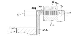
- FIG. 6A to 6C are diagrams showing modifications of the connecting portion of the shaft member, FIG. 6A showing modification 1, FIG. 6B showing modification 2, and FIG. 6C showing modification 3.
- the shaft member 32b has conductive portions 32b1f and 32b1s and a non-conductive portion 32b2, as in the embodiment of FIG.
- the conductive portions 32b1f and 32b1s include a magnetic conductive portion 32b1f made of steel or the like and a non-magnetic conductive portion 32b1s made of stainless steel or the like.
- the conductive portions 32b1f and 32b1s of the shaft member 32b are connected to the pole piece 32a via the non-conductive portion 32b2. Furthermore, the non-magnetic conductive portion 32b1s is interposed between the magnetic conductive portion 32b1f and the non-conductive portion 32b2.
- the conductive portion 32b1f having magnetism may constitute the shaft portion of the shaft member 32b, and the non-magnetic conductive portion 32b1s may constitute the flange portion of the shaft member.
- the non-conductive portion 32b2 of the shaft member 32b is elongated in the axial direction, so that the connecting portion between the conductive portion 32b1s and the non-conductive portion 32b2 is separated from the pole piece 32a in the axial direction.
- the conductive portion 32b1s of the shaft member 32b can be arranged so as to overlap with the region R1 but be separated from the region R1a that generates a relatively large loss.
- the conductive portion 32b1s of the shaft member 32b is arranged outside the region R1a, thereby suppressing reduction in torque and efficiency of the magnetic modulation gear caused by eddy currents. Furthermore, the effect that the shape of the non-conductive portion 32b2 can be simplified and the non-conductive portion 32b2 can be easily formed can be obtained.
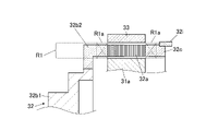
- Modification 2 (FIG. 6B) is an example in which at least a portion of the non-conductive portion 32b2 protrudes in the radial direction, and the conductive portion 32b1s is connected to the protruding portion. With such a configuration, the conductive portion 32b1s can be arranged outside the region R1.
- the conductive portion 32b1s of the shaft member 32b is arranged outside the region R1, thereby suppressing reduction in torque and efficiency of the magnetic modulation gear caused by eddy currents. Further, the conductive portion 32b1s of the shaft member 32b can be brought closer to the magnetic pole piece 32a in the axial direction, thereby contributing to the compactness of the magnetic modulation gear in the axial direction.
- Modification 3 (FIG. 6C) is an example in which the maximum outer diameter of the shaft member 32b is larger than the outer diameter of the magnetic pole piece 32a, and the conductive portion 32b1s of the shaft member 32b is connected from the radially outer side of the non-conductive portion 32b2. . Even in such a configuration, as shown in FIG. 6C, the connecting portion between the conductive portion 32b1s and the non-conductive portion 32b2 can be separated from the pole piece 32a in the axial direction by configuring the non-conductive portion 32b2 to be long in the axial direction. can be done.
- the conductive portion 32b1s can be arranged outside the region R1a, and reduction in torque and efficiency of the magnetic modulation gear caused by eddy current can be suppressed. Furthermore, the effect that the shape of the non-conductive portion 32b2 can be simplified and the non-conductive portion 32b2 can be easily formed can be obtained.
- the non-conductive portion 32b2 may be shaped to protrude radially outward, and the conductive portion 32b1s may be connected to the protruded portion.
- the conductive portion 32b1s can be arranged outside the region R1. According to this configuration, it is possible to bring the conductive portion 32b1s of the shaft member 32b closer to the pole piece 32a in the axial direction while suppressing a decrease in the torque and efficiency of the magnetic modulation gear caused by eddy currents. The effect of being able to contribute to the compactization of the direction is obtained.
- FIG. 7A to 7C are diagrams showing modifications of the connecting structure of the shaft members, FIG. 7A showing modification 4, FIG. 7B showing modification 5, and FIG. 7C showing modification 6.
- FIG. 7A shows modification 4
- FIG. 7B shows modification 5
- FIG. 7C showing modification 6.
- the conductive portion 32b1s and the non-conductive portion 32b2 of the shaft member 32b, or the two conductive portions 32b1f and 32b1s, are connected via a connecting member 32h such as a bolt.
- the connecting member 32h is made of a non-magnetic conductor such as stainless steel.
- Modification 4 (FIG. 7A) is an example in which a conductive portion 32b1s is connected to the axial end of the non-conductive portion 32b2 via a connecting member 32h.
- the connecting member 32h By lengthening the non-conductive portion 32b2 in the axial direction, the connecting member 32h is separated from the pole piece 32a in the axial direction.
- the connecting member 32h which is a conductor, can be arranged so as to overlap with the region R1 but away from the region R1a that generates a relatively large loss.
- Modified Example 4 by disposing the connecting member 32h outside the region R1a, it is possible to suppress a decrease in the torque and efficiency of the magnetic modulation gear caused by eddy currents. Furthermore, it is possible to simplify the shape of the non-conductive portion 32b2, and to easily connect the conductive portion 32b1s and the non-conductive portion 32b2.
- Modification 5 (FIG. 7B) is an example in which a conductive portion 32b1s forming a flange portion is connected via a connecting member 32h to an end portion in the axial direction of a conductive portion 32b1f forming a shaft portion.
- the connecting member 32h has a head portion arranged on the side closer to the pole piece 32a and a screw portion arranged on the side farther from the pole piece 32a in the axial direction. Since the connecting portion of the two conductive portions 32b1s and 32b1f is spaced radially inward from the pole piece 32a, the connecting member 32h, which is a conductor, can be arranged outside the regions R1a and R1.
- connection member 32h is arranged outside the regions R1a and R1, thereby suppressing the reduction in the torque and efficiency of the magnetic modulation gear caused by eddy currents. Furthermore, the connecting portion of the two conductive portions 32b1f and 32b1s of the shaft member 32b can be brought closer to the magnetic pole piece 32a in the axial direction, thereby contributing to the compactness of the magnetic modulation gear in the axial direction.
- Modification 6 (FIG. 7C) is an example in which the maximum outer diameter of the shaft member 32b is larger than the outer diameter of the magnetic pole piece 32a, and the conductive portion 32b1s is connected to the radially outer side of the non-conductive portion 32b2. Also in such a configuration, the conductive portion 32b1s forming the flange portion is connected to the end portion in the axial direction of the conductive portion 32b1f forming the shaft portion via the connecting member 32h.
- the connecting member 32h has a head portion arranged on the side closer to the pole piece 32a and a screw portion arranged on the side farther from the pole piece 32a in the axial direction.
- the connecting member 32h which is a conductor, can be arranged outside the regions R1a and R1.
- connection member 32h is arranged outside the regions R1a and R1, thereby suppressing the reduction in the torque and efficiency of the magnetic modulation gear caused by eddy currents. Furthermore, the connecting portion of the two conductive portions 32b1f and 32b1s of the shaft member 32b can be brought closer to the magnetic pole piece 32a in the axial direction, thereby contributing to the compactness of the magnetic modulation gear in the axial direction.
- FIG. 8A and 8B are diagrams showing modifications including other conductive parts, FIG. 8A showing modification 7 and FIG. 8B showing modification 8.
- FIG. 8A showing modification 7
- FIG. 8B showing modification 8.
- Modification 7 is an example in which a sensor 35 containing a conductor is provided in the vicinity of the low-speed rotor 32.
- the sensor 35 is, for example, an encoder that detects rotation, but may be various sensors such as a temperature sensor.
- the sensor 35 By arranging the sensor 35 to face the non-conductive portion 32b2 of the shaft member 32b, the sensor 35 can be arranged to face the portion of the shaft member 32b that displaces at the same speed as the magnetic pole piece 32a, and It is axially spaced from the pole piece 32a.
- the conductor portion of the sensor 35 can be arranged outside the region R1a.
- the sensor 35 may be arranged so as to overlap the region R1 while deviating from the region R1a.
- Modification 8 (FIG. 8B) is an example in which a plate member 32i, which is a conductor, is provided on the extending portion 32c.
- the low-speed rotor 32 corresponds to an example of the rotor according to the invention
- the plate member 32i corresponds to an example of the conductive member according to the invention.
- the plate member 32i may be a member for any purpose, such as a reinforcing member or a non-detecting member for electrically detecting rotation.
- the plate member 32i may be a member fixed to the extending portion 32c in a partial range in the circumferential direction, or may be an annular member positioned over the entire circumference in the circumferential direction.
- the plate member 32i can be axially spaced apart from the pole piece 32a by being fixed to the extension 32c.
- the plate member 32i which is a conductor, can be arranged outside the region R1a, and the reduction in loss and torque of the magnetic modulation gear due to eddy currents can be suppressed.
- the plate member may be arranged so as to overlap the region R1 while deviating from the region R1a.
- the magnetic modulation gear 30 that decelerates or accelerates the rotational motion by rotating the low-speed rotor 32 and the high-speed rotor 31 has been described.
- the pole pieces may be fixed, the inner pole magnets integrated with the fast shaft, and the outer pole magnets integrated with the slow shaft. Even in this case, the configuration integrated with the multiple pole pieces rotates relative to the inner and outer pole magnets, so the configuration can be considered a rotor with multiple pole pieces.
- the number of parts that are conductors shown in the above embodiments can be changed in various ways.
- the shaft member integrated with the plurality of pole pieces protrudes toward the load side, but the shaft member may be located on the opposite side of the load. Other details shown in the embodiments can be changed as appropriate without departing from the scope of the invention.
- the present invention can be suitably applied to various machines for general industrial use because of its features such as high efficiency, low maintenance, quietness (low noise), and cleanness (oil-free).
- it is highly useful for application to the following uses.
- ⁇ Robot joint gears Due to the torque limit function and low rigidity of the magnetic modulation gear, it has high safety and compliance functions.
- ⁇ Power generation speed increasing gear Equipped with a torque limit function, it does not apply an excessive load even during high loads such as strong winds in wind power generation. Highly useful for maintenance saving.
- ⁇ Vacuum equipment semiconductor manufacturing equipment: By using magnet coupling, the speed reduction function and the coupling function can be demonstrated independently, and the speed reduction gear can be eliminated (or the input motor can be made smaller).
- the present invention can be used for magnetic modulation gears and gear motors.
Landscapes
- Engineering & Computer Science (AREA)
- General Engineering & Computer Science (AREA)
- Mechanical Engineering (AREA)
- Power Engineering (AREA)
- Dynamo-Electric Clutches, Dynamo-Electric Brakes (AREA)
Abstract
Description
周方向に配列された複数の外極磁石と、前記複数の外極磁石よりも径方向内方で周方向に配列された複数の磁極片と、前記複数の磁極片よりも径方向内方で周方向に配列された複数の内極磁石と、を備える磁気変調ギヤであって、
前記複数の磁極片と連結されるシャフト部材を更に備え、
前記シャフト部材は、非導電部と導電部とを含み、
前記導電部が前記非導電部を介して前記複数の磁極片に連結されている。
周方向に配列された複数の外極磁石と、前記複数の外極磁石よりも径方向内方で周方向に配列された複数の磁極片と、前記複数の磁極片よりも径方向内方で周方向に配列された複数の内極磁石と、を備える磁気変調ギヤであって、
径方向における前記複数の外極磁石の内周端と前記複数の内極磁石の外周端との間で、かつ、軸方向における前記磁極片との距離が3mm未満である領域に導体を有さない。
電動モータと、
前記電動モータから動力を受ける上記の磁気変調ギヤと、
を備える。
磁気変調ギヤ30は、高速ロータ31に入力された回転運動を減速して低速ロータ32から出力する減速運転と、低速ロータ32に入力された回転運動を増速して高速ロータ31から出力する増速運転とが可能である。
続いて、磁極片32aの近くに、磁性を有さない任意の導体51を配置した場合の磁気変調ギヤ30のトルク及び効率の変化について説明する。
磁気変調ギヤ30は、図1に示すように、領域R1aに導体を有さない。言い換えれば、導電性を有する部品は、領域R1aの外に配置される、なお、磁気変調ギヤ30は、領域R1に導体を有さない構成であってもよい。言い換えれば、導電性を有する部品は、領域R1aの外に配置されると見なしてもよい。
シャフト部材32bの導電部32b1は非導電部32b2を介して磁極片32aに連結される。導電部32b1と非導電部32b2との連結部は、領域R1又は領域R1aに重ならないように配置される。言い換えれば、導電部32b1が、複数の外極磁石33の内周端よりも径方向外方の領域、複数の内極磁石31aの外周端よりも径方向内方の領域、磁極片32aとの軸方向距離がXmm以上の領域とを合わせた領域内に配置される。
低速ロータ32に接続される導電性を有する部品(例えばリング部材32g)は、領域R1又は領域R1aの外に配置される。言い換えれば、上記の部品(例えばリング部材32g)が、複数の外極磁石33の内周端よりも径方向外方の領域と、複数の内極磁石31aの外周端よりも径方向内方の領域と、磁極片32aとの軸方向距離がXmm以上の領域とを合わせた領域内に配置される。
図5は、本発明の実施形態に係るギヤモータを示す断面図である。本実施形態のギヤモータ1は、回転動力を出力するモータ(電動モータ)20と、モータ20の回転動力を受ける磁気変調ギヤ30と、モータ20及び磁気変調ギヤ30を収容するケーシング10、負荷側カバー11及び反負荷側カバー12とを備える。
ギヤモータ1は、モータ20が駆動されることでモータロータ21に回転動力が出力され、当該回転動力が磁気変調ギヤ30に入力され、前述した磁気変調ギヤ30の動作によって、回転運動が減速されて低速ロータ32を介して出力される。
ギヤモータ1においても、低速ロータ32のシャフト部材32bの導電部32b1が、非導電部32b2を介して磁極片32aに連結されることで、シャフト部材32bの導電部32b1が領域R1又は領域R1aの外に配置される。
続いて、図6A~図8Bを参照して変形例1~8について説明する。図6A~図8Bにおいては、主に外極磁石33、低速ロータ32及び内極磁石31aを図示し、他の幾つかの部品は図示を省略している。図6A~図8Bに示した変形例1~8の磁気変調ギヤは、図1の磁気変調ギヤ30又は図5のギヤモータ1と同様にその他の部品を有する構成であってもよい。
図6A~図6Cは、シャフト部材の連結部の変形例を示す図であり、図6Aは変形例1、図6Bは変形例2、図6Cは変形例3を示す。変形例1~3において、シャフト部材32bは、図1の実施形態と同様に、導電部32b1f、32b1sと非導電部32b2とを有する。一方、導電部32b1f、32b1sは、例えば鉄鋼等を材質とする磁性を有する導電部32b1fと、ステンレス等を材質とする非磁性の導電部32b1sとを含む。
図7A~図7Cは、シャフト部材の連結構造の変形例を示す図であり、図7Aは変形例4、図7Bは変形例5、図7Cは変形例6を示す。変形例4~6においては、ボルト等の連結部材32hを介してシャフト部材32bの導電部32b1sと非導電部32b2、あるいは、2つの導電部32b1f、32b1sが連結される。連結部材32hはステンレスなどの非磁性の導体から構成される。
図8A及び図8Bは、その他の導電性部品を含んだ変形例を示す図であり、図8Aは変形例7、図8Bは変形例8を示す。
・ロボット関節用ギヤ : 磁気変調ギヤによるトルクリミット機能や低剛性の特徴から、高い安全性やコンプライアンス機能を有する。
・発電用増速機 :トルクリミット機能を備えることから、風力発電での強風時等の高負荷時でも無理な負荷が掛からない。省メンテナンスの有用性が高い。
・真空装置(半導体製造装置) : マグネットカップリング用途での利用により、減速機能とカップリング機能を単体で発揮でき、減速用ギヤを不要に(又は入力用モータを小型に)できるため、装置のコンパクト化を図れる。
・食品機械 :グリスレス(オイルフリー)、軸シール(オイルシール)の摩耗粉が生じない、軸構造の分解が容易で内部洗浄が簡単、といった特徴から、衛生管理面での有用性が高い。
・オフィス/家庭用機器 : 非接触動力伝達のため振動騒音が少ないといった特徴から、室内空間の静粛性を確保できる。
10 ケーシング
11 負荷側カバー
12 反負荷側カバー
13a、13b、13Aa、13Ab、13c、13d 軸受
20 モータ
21a シャフト
21b ロータヨーク
21c ロータ磁石
22 モータステータ
22a ステータコア
22b コイル
30 磁気変調ギヤ
31 高速ロータ
31a 内極磁石
31b ロータヨーク
32 低速ロータ(ロータ)
32a 磁極片
32b シャフト部材
32b1 導電部
32b1s 非磁性の導電部
32b1f 磁性を有する導電部
32b2 非導電部
32c 延在部
32g リング部材
32h 連結部材
32i プレート部材(導電性部材)
33 外極磁石
33a ヨーク部
35 センサ
R1、R1a 領域
Claims (7)
- 周方向に配列された複数の外極磁石と、前記複数の外極磁石よりも径方向内方で周方向に配列された複数の磁極片と、前記複数の磁極片よりも径方向内方で周方向に配列された複数の内極磁石と、を備える磁気変調ギヤであって、
前記複数の磁極片と連結されるシャフト部材を更に備え、
前記シャフト部材は、非導電部と導電部とを含み、
前記導電部が前記非導電部を介して前記複数の磁極片に連結されている、
磁気変調ギヤ。 - 前記導電部と前記非導電部との連結部が、前記外極磁石の内周端よりも径方向外方の領域内、あるいは、前記内極磁石の外周端よりも径方向内方の領域内に位置する、
請求項1記載の磁気変調ギヤ。 - 前記導電部と前記非導電部との連結部が、前記外極磁石の内周端よりも径方向外方の領域と、前記内極磁石の外周端よりも径方向内方の領域と、前記磁極片よりも軸方向に3mm以上離間した領域とを合わせた領域内に位置する、
請求項1記載の磁気変調ギヤ。 - 前記非導電部と前記導電部とを連結する連結部材、又は、前記シャフト部材と一体化されたロータに接続された導電性部材を更に備え、
前記連結部材又は前記導電性部材が、前記外極磁石の内周端よりも径方向外方の領域と、前記内極磁石の外周端よりも径方向内方の領域と、前記磁極片よりも軸方向に3mm以上離間した領域とを合わせた領域内に位置する、
請求項1から請求項3のいずれか一項に記載の磁気変調ギヤ。 - 周方向に配列された複数の外極磁石と、前記複数の外極磁石よりも径方向内方で周方向に配列された複数の磁極片と、前記複数の磁極片よりも径方向内方で周方向に配列された複数の内極磁石と、を備える磁気変調ギヤであって、
径方向における前記複数の外極磁石の内周端と前記複数の内極磁石の外周端との間で、かつ、軸方向における前記磁極片との距離が3mm未満である領域に導体を有さない、
磁気変調ギヤ。 - 前記シャフト部材の前記導電部、前記連結部材、前記導電性部材、前記導体、又は、これらのうちの複数は非磁性体である、
請求項1から請求項5のいずれか一項に記載の磁気変調ギヤ。 - 電動モータと、
前記電動モータから動力を受ける請求項1から請求項6のいずれか一項に記載の磁気変調ギヤと、
を備えるギヤモータ。
Priority Applications (1)
| Application Number | Priority Date | Filing Date | Title |
|---|---|---|---|
| JP2023542326A JPWO2023022007A1 (ja) | 2021-08-17 | 2022-08-04 |
Applications Claiming Priority (2)
| Application Number | Priority Date | Filing Date | Title |
|---|---|---|---|
| JP2021132953 | 2021-08-17 | ||
| JP2021-132953 | 2021-08-17 |
Related Child Applications (1)
| Application Number | Title | Priority Date | Filing Date |
|---|---|---|---|
| US18/440,855 Continuation US20240186878A1 (en) | 2021-08-17 | 2024-02-13 | Magnetic modulation gear and gear motor |
Publications (1)
| Publication Number | Publication Date |
|---|---|
| WO2023022007A1 true WO2023022007A1 (ja) | 2023-02-23 |
Family
ID=85239530
Family Applications (1)
| Application Number | Title | Priority Date | Filing Date |
|---|---|---|---|
| PCT/JP2022/029944 WO2023022007A1 (ja) | 2021-08-17 | 2022-08-04 | 磁気変調ギヤ及びギヤモータ |
Country Status (2)
| Country | Link |
|---|---|
| JP (1) | JPWO2023022007A1 (ja) |
| WO (1) | WO2023022007A1 (ja) |
Citations (6)
| Publication number | Priority date | Publication date | Assignee | Title |
|---|---|---|---|---|
| JP2012147513A (ja) * | 2011-01-07 | 2012-08-02 | Hitachi Ltd | 磁気ギヤ及びそれを有する回転機 |
| JP2013011298A (ja) * | 2011-06-29 | 2013-01-17 | Hitachi Ltd | 磁気式歯車機構 |
| JP2016142407A (ja) * | 2015-02-05 | 2016-08-08 | 株式会社Ihi | ターボ圧縮機 |
| JP2017050943A (ja) * | 2015-08-31 | 2017-03-09 | スズキ株式会社 | 回転電機 |
| US20170373582A1 (en) * | 2016-06-23 | 2017-12-28 | Goodrich Actuation Systems Limited | Pole-Piece Structure for a Magnetic Gear |
| JP2020133790A (ja) | 2019-02-21 | 2020-08-31 | 国立大学法人東北大学 | 回転電機 |
-
2022
- 2022-08-04 JP JP2023542326A patent/JPWO2023022007A1/ja active Pending
- 2022-08-04 WO PCT/JP2022/029944 patent/WO2023022007A1/ja active Application Filing
Patent Citations (6)
| Publication number | Priority date | Publication date | Assignee | Title |
|---|---|---|---|---|
| JP2012147513A (ja) * | 2011-01-07 | 2012-08-02 | Hitachi Ltd | 磁気ギヤ及びそれを有する回転機 |
| JP2013011298A (ja) * | 2011-06-29 | 2013-01-17 | Hitachi Ltd | 磁気式歯車機構 |
| JP2016142407A (ja) * | 2015-02-05 | 2016-08-08 | 株式会社Ihi | ターボ圧縮機 |
| JP2017050943A (ja) * | 2015-08-31 | 2017-03-09 | スズキ株式会社 | 回転電機 |
| US20170373582A1 (en) * | 2016-06-23 | 2017-12-28 | Goodrich Actuation Systems Limited | Pole-Piece Structure for a Magnetic Gear |
| JP2020133790A (ja) | 2019-02-21 | 2020-08-31 | 国立大学法人東北大学 | 回転電機 |
Also Published As
| Publication number | Publication date |
|---|---|
| JPWO2023022007A1 (ja) | 2023-02-23 |
Similar Documents
| Publication | Publication Date | Title |
|---|---|---|
| US6064132A (en) | Armature structure of a radial rib winding type rotating electric machine | |
| US7474028B2 (en) | Motor | |
| US20180248429A1 (en) | Motor | |
| EP1643613A2 (en) | Electric motor in which the stator laminations are of different thickness and/or material to the rotor laminations | |
| US10637305B2 (en) | Double stator-type rotary machine | |
| US20230046567A1 (en) | Magnetic geared rotary electric machine | |
| US20140125166A1 (en) | Rotating electrical machine | |
| US11990796B2 (en) | Rotor, motor using the rotor and electronic device | |
| US20140265704A1 (en) | Rotor including permanent magnets having different thicknesses and motor including same | |
| WO2023022007A1 (ja) | 磁気変調ギヤ及びギヤモータ | |
| JP2011172359A (ja) | 分割型回転子及び電動機 | |
| KR100688158B1 (ko) | 두 개의 회전자를 갖는 전동기 | |
| US20240186878A1 (en) | Magnetic modulation gear and gear motor | |
| JP2017050942A (ja) | 回転電機 | |
| WO2023022006A1 (ja) | 磁気変調ギヤ及びギヤモータ | |
| JP4556408B2 (ja) | クローポール形回転機 | |
| WO2003043164A1 (en) | Dynamo-electric machine | |
| JP2012200053A (ja) | 埋込磁石形回転電機 | |
| KR20210074696A (ko) | 다단의 회전자를 구비한 고속 전동기 | |
| CN110601478A (zh) | 一种双定子电机 | |
| JP2020022236A (ja) | モータ | |
| US20230318375A1 (en) | Rotary electric machine | |
| JP3671928B2 (ja) | 回転電機のアウターロータ構造 | |
| CN109038890B (zh) | 电机 | |
| WO2022219923A1 (ja) | 回転子及び電動機 |
Legal Events
| Date | Code | Title | Description |
|---|---|---|---|
| 121 | Ep: the epo has been informed by wipo that ep was designated in this application |
Ref document number: 22858328 Country of ref document: EP Kind code of ref document: A1 |
|
| WWE | Wipo information: entry into national phase |
Ref document number: 2023542326 Country of ref document: JP |
|
| WWE | Wipo information: entry into national phase |
Ref document number: 2022858328 Country of ref document: EP |
|
| NENP | Non-entry into the national phase |
Ref country code: DE |
|
| ENP | Entry into the national phase |
Ref document number: 2022858328 Country of ref document: EP Effective date: 20240318 |