WO2023013625A1 - 積層中空成形体 - Google Patents
積層中空成形体 Download PDFInfo
- Publication number
- WO2023013625A1 WO2023013625A1 PCT/JP2022/029606 JP2022029606W WO2023013625A1 WO 2023013625 A1 WO2023013625 A1 WO 2023013625A1 JP 2022029606 W JP2022029606 W JP 2022029606W WO 2023013625 A1 WO2023013625 A1 WO 2023013625A1
- Authority
- WO
- WIPO (PCT)
- Prior art keywords
- core layer
- layer
- walls
- double
- cell
- Prior art date
- Legal status (The legal status is an assumption and is not a legal conclusion. Google has not performed a legal analysis and makes no representation as to the accuracy of the status listed.)
- Ceased
Links
Images






Classifications
-
- B—PERFORMING OPERATIONS; TRANSPORTING
- B32—LAYERED PRODUCTS
- B32B—LAYERED PRODUCTS, i.e. PRODUCTS BUILT-UP OF STRATA OF FLAT OR NON-FLAT, e.g. CELLULAR OR HONEYCOMB, FORM
- B32B3/00—Layered products comprising a layer with external or internal discontinuities or unevennesses, or a layer of non-planar shape; Layered products comprising a layer having particular features of form
- B32B3/10—Layered products comprising a layer with external or internal discontinuities or unevennesses, or a layer of non-planar shape; Layered products comprising a layer having particular features of form characterised by a discontinuous layer, i.e. formed of separate pieces of material
- B32B3/12—Layered products comprising a layer with external or internal discontinuities or unevennesses, or a layer of non-planar shape; Layered products comprising a layer having particular features of form characterised by a discontinuous layer, i.e. formed of separate pieces of material characterised by a layer of regularly- arranged cells, e.g. a honeycomb structure
-
- B—PERFORMING OPERATIONS; TRANSPORTING
- B32—LAYERED PRODUCTS
- B32B—LAYERED PRODUCTS, i.e. PRODUCTS BUILT-UP OF STRATA OF FLAT OR NON-FLAT, e.g. CELLULAR OR HONEYCOMB, FORM
- B32B27/00—Layered products comprising a layer of synthetic resin
- B32B27/12—Layered products comprising a layer of synthetic resin next to a fibrous or filamentary layer
-
- B—PERFORMING OPERATIONS; TRANSPORTING
- B32—LAYERED PRODUCTS
- B32B—LAYERED PRODUCTS, i.e. PRODUCTS BUILT-UP OF STRATA OF FLAT OR NON-FLAT, e.g. CELLULAR OR HONEYCOMB, FORM
- B32B27/00—Layered products comprising a layer of synthetic resin
- B32B27/32—Layered products comprising a layer of synthetic resin comprising polyolefins
-
- B—PERFORMING OPERATIONS; TRANSPORTING
- B32—LAYERED PRODUCTS
- B32B—LAYERED PRODUCTS, i.e. PRODUCTS BUILT-UP OF STRATA OF FLAT OR NON-FLAT, e.g. CELLULAR OR HONEYCOMB, FORM
- B32B5/00—Layered products characterised by the non- homogeneity or physical structure, i.e. comprising a fibrous, filamentary, particulate or foam layer; Layered products characterised by having a layer differing constitutionally or physically in different parts
- B32B5/22—Layered products characterised by the non- homogeneity or physical structure, i.e. comprising a fibrous, filamentary, particulate or foam layer; Layered products characterised by having a layer differing constitutionally or physically in different parts characterised by the presence of two or more layers which are next to each other and are fibrous, filamentary, formed of particles or foamed
- B32B5/24—Layered products characterised by the non- homogeneity or physical structure, i.e. comprising a fibrous, filamentary, particulate or foam layer; Layered products characterised by having a layer differing constitutionally or physically in different parts characterised by the presence of two or more layers which are next to each other and are fibrous, filamentary, formed of particles or foamed one layer being a fibrous or filamentary layer
- B32B5/26—Layered products characterised by the non- homogeneity or physical structure, i.e. comprising a fibrous, filamentary, particulate or foam layer; Layered products characterised by having a layer differing constitutionally or physically in different parts characterised by the presence of two or more layers which are next to each other and are fibrous, filamentary, formed of particles or foamed one layer being a fibrous or filamentary layer another layer next to it also being fibrous or filamentary
- B32B5/265—Layered products characterised by the non- homogeneity or physical structure, i.e. comprising a fibrous, filamentary, particulate or foam layer; Layered products characterised by having a layer differing constitutionally or physically in different parts characterised by the presence of two or more layers which are next to each other and are fibrous, filamentary, formed of particles or foamed one layer being a fibrous or filamentary layer another layer next to it also being fibrous or filamentary characterised by one fibrous or filamentary layer being a non-woven fabric layer
-
- B—PERFORMING OPERATIONS; TRANSPORTING
- B32—LAYERED PRODUCTS
- B32B—LAYERED PRODUCTS, i.e. PRODUCTS BUILT-UP OF STRATA OF FLAT OR NON-FLAT, e.g. CELLULAR OR HONEYCOMB, FORM
- B32B7/00—Layered products characterised by the relation between layers; Layered products characterised by the relative orientation of features between layers, or by the relative values of a measurable parameter between layers, i.e. products comprising layers having different physical, chemical or physicochemical properties; Layered products characterised by the interconnection of layers
- B32B7/02—Physical, chemical or physicochemical properties
-
- B—PERFORMING OPERATIONS; TRANSPORTING
- B32—LAYERED PRODUCTS
- B32B—LAYERED PRODUCTS, i.e. PRODUCTS BUILT-UP OF STRATA OF FLAT OR NON-FLAT, e.g. CELLULAR OR HONEYCOMB, FORM
- B32B2250/00—Layers arrangement
- B32B2250/05—5 or more layers
-
- B—PERFORMING OPERATIONS; TRANSPORTING
- B32—LAYERED PRODUCTS
- B32B—LAYERED PRODUCTS, i.e. PRODUCTS BUILT-UP OF STRATA OF FLAT OR NON-FLAT, e.g. CELLULAR OR HONEYCOMB, FORM
- B32B2262/00—Composition or structural features of fibres which form a fibrous or filamentary layer or are present as additives
- B32B2262/02—Synthetic macromolecular fibres
- B32B2262/0246—Acrylic resin fibres
-
- B—PERFORMING OPERATIONS; TRANSPORTING
- B32—LAYERED PRODUCTS
- B32B—LAYERED PRODUCTS, i.e. PRODUCTS BUILT-UP OF STRATA OF FLAT OR NON-FLAT, e.g. CELLULAR OR HONEYCOMB, FORM
- B32B2262/00—Composition or structural features of fibres which form a fibrous or filamentary layer or are present as additives
- B32B2262/02—Synthetic macromolecular fibres
- B32B2262/0253—Polyolefin fibres
-
- B—PERFORMING OPERATIONS; TRANSPORTING
- B32—LAYERED PRODUCTS
- B32B—LAYERED PRODUCTS, i.e. PRODUCTS BUILT-UP OF STRATA OF FLAT OR NON-FLAT, e.g. CELLULAR OR HONEYCOMB, FORM
- B32B2262/00—Composition or structural features of fibres which form a fibrous or filamentary layer or are present as additives
- B32B2262/02—Synthetic macromolecular fibres
- B32B2262/0261—Polyamide fibres
-
- B—PERFORMING OPERATIONS; TRANSPORTING
- B32—LAYERED PRODUCTS
- B32B—LAYERED PRODUCTS, i.e. PRODUCTS BUILT-UP OF STRATA OF FLAT OR NON-FLAT, e.g. CELLULAR OR HONEYCOMB, FORM
- B32B2262/00—Composition or structural features of fibres which form a fibrous or filamentary layer or are present as additives
- B32B2262/02—Synthetic macromolecular fibres
- B32B2262/0276—Polyester fibres
-
- B—PERFORMING OPERATIONS; TRANSPORTING
- B32—LAYERED PRODUCTS
- B32B—LAYERED PRODUCTS, i.e. PRODUCTS BUILT-UP OF STRATA OF FLAT OR NON-FLAT, e.g. CELLULAR OR HONEYCOMB, FORM
- B32B2262/00—Composition or structural features of fibres which form a fibrous or filamentary layer or are present as additives
- B32B2262/10—Inorganic fibres
- B32B2262/101—Glass fibres
-
- B—PERFORMING OPERATIONS; TRANSPORTING
- B32—LAYERED PRODUCTS
- B32B—LAYERED PRODUCTS, i.e. PRODUCTS BUILT-UP OF STRATA OF FLAT OR NON-FLAT, e.g. CELLULAR OR HONEYCOMB, FORM
- B32B2262/00—Composition or structural features of fibres which form a fibrous or filamentary layer or are present as additives
- B32B2262/10—Inorganic fibres
- B32B2262/103—Metal fibres
-
- B—PERFORMING OPERATIONS; TRANSPORTING
- B32—LAYERED PRODUCTS
- B32B—LAYERED PRODUCTS, i.e. PRODUCTS BUILT-UP OF STRATA OF FLAT OR NON-FLAT, e.g. CELLULAR OR HONEYCOMB, FORM
- B32B2262/00—Composition or structural features of fibres which form a fibrous or filamentary layer or are present as additives
- B32B2262/10—Inorganic fibres
- B32B2262/108—Rockwool fibres
-
- B—PERFORMING OPERATIONS; TRANSPORTING
- B32—LAYERED PRODUCTS
- B32B—LAYERED PRODUCTS, i.e. PRODUCTS BUILT-UP OF STRATA OF FLAT OR NON-FLAT, e.g. CELLULAR OR HONEYCOMB, FORM
- B32B2305/00—Condition, form or state of the layers or laminate
- B32B2305/10—Fibres of continuous length
- B32B2305/20—Fibres of continuous length in the form of a non-woven mat
-
- B—PERFORMING OPERATIONS; TRANSPORTING
- B32—LAYERED PRODUCTS
- B32B—LAYERED PRODUCTS, i.e. PRODUCTS BUILT-UP OF STRATA OF FLAT OR NON-FLAT, e.g. CELLULAR OR HONEYCOMB, FORM
- B32B2307/00—Properties of the layers or laminate
- B32B2307/70—Other properties
- B32B2307/732—Dimensional properties
- B32B2307/737—Dimensions, e.g. volume or area
- B32B2307/7375—Linear, e.g. length, distance or width
- B32B2307/7376—Thickness
-
- B—PERFORMING OPERATIONS; TRANSPORTING
- B32—LAYERED PRODUCTS
- B32B—LAYERED PRODUCTS, i.e. PRODUCTS BUILT-UP OF STRATA OF FLAT OR NON-FLAT, e.g. CELLULAR OR HONEYCOMB, FORM
- B32B2605/00—Vehicles
Definitions
- the present invention relates to a laminated hollow molded body, and more particularly to a laminated hollow molded body having a core layer such as a honeycomb core and used as a soundproofing member for automobiles.
- a laminated hollow molded body used for soundproofing members for automobiles, etc. generally has a core layer composed of a plurality of substantially hexagonal cylindrical hollow cells called a honeycomb core.
- a thermoplastic resin is used as a material for most of such core layers.
- a laminated structure comprising a thermoplastic resin hollow sheet material in which a plurality of columnar cells are arranged side by side, and a metal member joined to the hollow sheet material
- the hollow sheet member is formed with a molded recess thermally deformed by a metal member, and the metal member is joined to the molded recess.
- Such a laminated hollow molded article having a core layer with double standing walls is heat-press molded to have a plurality of regions with different heights of the core layer in order to obtain a desired member shape.
- an abnormal noise such as a crisp sound is generated from inside the laminated hollow molded product.
- An object of the present invention is to provide a laminated hollow molded article that is suppressed.
- the present invention provides a core layer in which cylindrical hollow cells are arranged in a plurality of rows, a surface layer provided on one surface of the core layer, and and a backing layer provided on the other surface of a core layer, wherein the core layer has double walls formed by two adjacent hollow cells, and the double walls is composed of two resin standing cell walls, and the core layer includes a first region having a first height and a second region having a second height lower than the first height and each of the two cell walls of the double walls of the core layer in the second region is in contact with the backing layer from a first end in contact with the surface layer Extending along each other in the same direction to a second end, at least one of the first end and the second end is a mass formed by integrally melting the two vertical cell walls. .
- the two cell walls of the double wall may extend linearly or arcuately from a first end in contact with the surface layer to a second end in contact with the backing layer.
- the thickness of the backing material layer may be thinner than the thickness of the front material layer, and the second end portion in contact with the backing material layer may be a massive portion formed by integrally melting the two vertical cell walls.
- Both the first end and the second end may be lumps formed by integrally melting the two vertical cell walls.
- each of the two cell walls extending linearly or arcuately from the first end to the second end of the double walls of the core layer in the second region is It may be thicker than the thickness of each cell standing wall of the double standing walls of the core layer in the first region.
- Each of the hollow cells of the core layer has a closed surface at one end and an open end at the other end, and the open ends of the hollow cells divide the internal space of the hollow cells into the surface layer or the back layer.
- the closed faces and the open ends of the hollow cells are arranged alternately on opposite sides of the core layer, and the closed faces of adjacent hollow cells are fused together.
- the relationship between the first height h1 of the core layer in the first region and the second height h2 of the core layer in the second region is expressed by the formula 0.2 ⁇ h2 /h 1 ⁇ 0.8 may be satisfied.
- the tensile strength of the core layer in the second region is 20 N or more in accordance with JIS K7127-1999 in the planar direction of the core layer and in the direction in which the double walls overlap in the same direction. good too.
- the double wall extends from the first end where the surface layer is in contact with the backing material. Extending linearly or arcuately to a second end contacting the layer, at least one of the first end and the second end being a mass formed by integrally melting two standing cell walls Therefore, it is possible to prevent the occurrence of abnormal noise such as crispness.
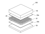
- FIG. 1 is an exploded perspective view showing an embodiment of a laminated hollow molded article according to the present invention
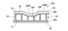
- 1 is a partial cross-sectional view showing an embodiment of a laminated hollow molded article according to the present invention
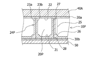
- FIG. 1 is an enlarged cross-sectional view showing an embodiment of a laminated hollow molded article according to the present invention
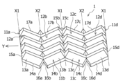
- FIG. 4 is a perspective view showing a manufacturing process of the core material used for the core layer in the laminated hollow molded article according to the present invention.
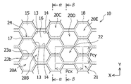
- 1 is a schematic plan view showing a core layer in a laminated hollow molded article according to the present invention
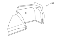
- FIG. 1 is a perspective view showing the appearance of a soundproofing member for an automobile obtained by hot-press molding laminated hollow molded articles in Examples or Comparative Examples.
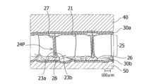
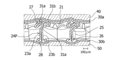
- FIG. 3 is a cross-sectional view showing the core layer in the region of Example 1.
- FIG. 3 is a plan view showing the core layer on the surface layer side of the region of Example 1.
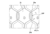
- FIG. 2 is a plan view showing the core layer on the backing layer side of the region of Example 1.
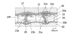
- FIG. 3 is a cross-sectional view showing a core layer in the region of Comparative Example 1.
- FIG. FIG. 11 is a cross-sectional view showing the core layer in the region of Example 3;
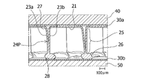
- FIG. 10 is a cross-sectional view showing the core layer in the region of Comparative Example 2;
- FIG. 10 is a cross-sectional view showing the core layer in the region of Comparative Example 3;
- FIG. 11 is a cross-sectional view showing the core layer in the region of Example 9;
- FIG. 11 is a cross-sectional view showing the core layer in the region of Example 7;
- FIG. 10 is a plan view of a test piece used in a tensile test of Example 10;
- FIG. 16B is a cross-sectional view along line BB of the test piece shown in FIG. 16A;
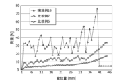
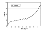
- 10 is a graph showing the results of tensile tests of Example 10, Comparative Example 6, and Comparative Example 7.
- FIG. 7 is a graph showing the results of a tensile test of Comparative Example 6 with different scales.
- the laminated hollow molded body 100 of the present embodiment includes a core layer 10, a surface layer 40 provided on one surface thereof, and a backing material provided on the other surface of the core layer 10. a layer 50;
- the core layer 10 is generally called a honeycomb core, and has cylindrical hollow cells 20 arranged in a plurality of rows.
- the laminated hollow molded article 100 of the present embodiment includes film layers 30a and 30b between the core layer 10 and the surface layer 40 and between the core layer 10 and the backing layer 50, respectively.
- the surface material layer 40 is placed on the inside of the vehicle interior, and when it is used as an exterior material, the surface material layer 40 is installed so as to be on the outside of the vehicle.
- the laminated hollow molded body 100 of the present embodiment is hot-press-molded in the lamination direction in a partial region thereof, as shown in FIG. 2 as an example. It has two regions, a first region 100N that is not pressed and a second region 100P that is hot pressed.
- Hot press molding is performed to match the shape of the laminated hollow molded body 100 to the shape of the vehicle compartment.
- the core layer 10 in particular of the laminated hollow molded body 100 is compressed, and the height of the core layer 10P in the hot press molded second region 100P is the same as that of the hot press molded first region. It is lower than the height of the core layer 10 of 100N.
- FIG. 2 illustrates a case where the surface layer 40 side of the core layer 10 is recessed by heat pressing
- the present invention is not limited to this, and the backing layer 50 side of the core layer 10 is recessed.
- both the surface layer 40 side and the backing layer 50 side of the core layer 10 may be recessed.
- the hollow cells 20 of the core layer 10 are substantially hexagonal cylinder-shaped closed surfaces that close the cell ends on one surface of the core layer 10 (the lower surface in FIG. 2). 21, and an open end 22 opened in a substantially hexagonal shape at the cell end on the other side (the upper side in FIG. 2) on the opposite side, and connecting the closed face 21 and the open end 22
- a part of the standing wall has a double standing wall 24 (also referred to as a double side wall).
- the double standing wall 24 is formed by stacking the respective cell standing walls (also referred to as cell side walls) of two adjacent hollow cells.
- the material of the core layer 10 is not particularly limited as long as it is a resin material that is commonly used as a soundproof layer in soundproof members for automobiles. ) are preferred.
- the height of the core layer 10 varies depending on which part of the automobile the laminated hollow molded body 100 is used for, so it is not limited to the following, but from the viewpoint of the soundproofing performance, strength, weight, etc. of the core layer 10, hot press molding is used.
- the range of 3 mm to 50 mm is preferred, and the range of 5 mm to 30 mm is more preferred, in the second region 100N that is not wrapped.
- the material of the surface material layer 40 and the back material layer 50 is not particularly limited as long as it is a material normally used for the surface material and the back material of the soundproof member for automobiles, but synthetic fibers such as polyester fiber, nylon fiber, acrylic fiber, etc. Fibers such as fibers, inorganic fibers such as glass wool and rock wool, and metal fibers such as aluminum fibers are also preferred. Felt is preferable as the fiber, and polyester fiber such as low-melting polyester fiber, glass wool, and other materials are preferably used. Moreover, as a manufacturing method of the felt, a manufacturing method such as needle punching, thermal bonding, or spunlacing is preferable.
- thermoplastic resins such as polypropylene (PP), polyethylene (PE), polyethylene terephthalate (PET), metal foil such as aluminum, and paper such as kraft paper are used alone or in combination by lamination. Anything is fine.
- foams such as thermoplastic resins such as urethane foam, foamed polyethylene, foamed nylon, and thermosetting resins may be used, and foams and fibers may be combined. good.
- the surface material layer 40 is preferably higher than the backing material layer 50 because the surface material layer 40 also serves as a design for the interior of the vehicle.
- the basis weight of the surface layer 40 is, for example, preferably 30 to 600 g/m 2 , more preferably 50 to 500 g/m 2 .
- the basis weight of the backing layer 50 is, for example, preferably 15 to 300 g/m 2 , more preferably 30 to 300 g/m 2 .
- the surface material layer 40 is preferably thicker than the back material layer 50 because the surface material layer 40 is required to have higher durability.
- the thickness of the surface material layer 40 is, for example, preferably 0.1 to 5 mm, more preferably 0.1 to 3 mm.
- the thickness of the backing layer 50 is, for example, preferably 0.1 to 5 mm, more preferably 0.1 to 2 mm.
- the thicknesses of the surface material layer 40, the backing material layer 50, and the film layer 30, which will be described later, are all measured in the stacking direction (the height direction or the vertical direction in FIG. 1).
- the material of the film layer 30 is not limited to these, for example, resin films such as polypropylene (PP), polyethylene (PE), polyethylene terephthalate (PET), and polyamide (PA) can be used.
- the thickness of the film layer 30 is not particularly limited, it is preferably 0.03 to 1.5 mm, more preferably 0.05 to 1.0 mm.
- the film layer 30 may be adhered to the core layer 10, the surface material layer 40 and the backing material layer 50 by thermal welding, or may be adhered via an adhesive (not shown).
- the adhesive is not particularly limited, for example, an epoxy-based, acrylic, olefin-based, or rubber-based adhesive can be used.
- the double standing walls 24 of the hollow cells 20 of the core layer 10 in the first region 100N not hot-press-molded are formed by two straight cell standing walls between the closed surface 21 and the open end 22 of the hollow cells 20. Although configured to extend substantially parallel in the same direction, the double walls 24P of the hollow cells 20P of the core layer 10P in the hot-press-molded second region 100P are different from this due to the hot-press molding. have a configuration.
- the hot-press-molded double wall 24P has two cell walls 23a from a first end 27 in contact with the surface layer 40 to a second end 28 in contact with the backing layer 50.
- 23b extend along each other in the same direction (hereinafter referred to as "extending portion 25"), but the second end 28 in contact with the backing layer 50 is formed by the two cell walls 23a, 23b integrally. It becomes a lump-like portion 26 that is substantially melted.
- the mass portion 26 is thicker than the combined thickness of the two cell standing walls 23a and 23b of the extension portion 25.
- a cavity may exist inside the massive portion 26, and the two vertical cell walls 23a and 23b may be fused together inside the massive portion 26. However, the mass 26 is not in a state of being separated from the original two cell walls even if a force is applied to separate them.
- the double vertical wall 24P formed by hot press molding has two vertical cell walls 23a and 23b at the first ends where both of the two cell vertical walls 23a and 23b are in contact with the surface layer 40.
- the second end Extending from the portion 27 to a second end 28 in contact with the backing layer 50 while remaining along each other in the same direction, the second end is where the two cell standing walls 23a, 23b are fused together. It is a massive portion 26, and does not have a portion where the two standing walls of the cells are deformed into different shapes and partially fused together. Therefore, even if a force is applied to the double standing wall 24P, an abnormal noise such as crisping is not generated.
- the tensile strength in the planar direction of the core layer 10 is extremely high due to the formation of such massive portions 26 in the hot-press-molded double walls 24P. It is preferably 20 N or more in the manufacturing direction Y of the core layer shown in FIGS. 4 and 5, although the details will be described later. If the tensile strength of the core layer is less than 20 N, the lumped portion 26 is not formed in the hot-press-molded double standing wall, and the two standing cell walls as described above are deformed into different shapes, resulting in a plurality of portions. It is a double standing wall fused together.
- a core layer having a tensile strength of less than 20 N when a force is applied to the hollow cells, the fused portions are peeled off, causing an abnormal crisp sound.
- the tensile strength of the core layer 10 is measured according to JIS K7127-1999 by a test in which the direction in which the double wall 24P overlaps is the tensile direction.
- the tensile strength of the core layer is more preferably 22N or more, still more preferably 24N or more. Although the upper limit is not particularly limited, it will be 200 N or less, for example.
- the two cell standing walls 23a and 23b extend linearly from the first end portion 27 to the second end portion 28, so that they extend along each other in the same direction.
- the two cell standing walls 23a, 23b have been subjected to heat press molding as described above, they are subjected to heat shrinkage to form an arcuate shape from the first end 27 to the second end 28. may extend to If arched, they can extend along each other in the same direction.
- the two cell walls 23a and 23b are straight or arcuate and extend along each other in the same direction by bending in the same direction without contacting each other, the crispness and the like can be obtained. It is possible to prevent the occurrence of abnormal noise. Further, FIG.
- the massive portion 26 of the double wall 24P is provided on the side of the closed surface 21 of the hollow cell 20P, but the present invention is not limited to this, and the massive portion 26 is the opening of the hollow cell 20P. It may be provided on the end 22 side, or may be provided on both the closed surface 21 side and the open end 23 side.
- the double standing wall 24P in which at least one end is the massive portion 26 and the two cell standing walls 23a and 23b extend along the same direction from one end to the other in a linear or arched shape, It can be produced by adjusting conditions such as the heating temperature for hot press molding of the laminated hollow molded body 100, the compression ratio of the core layer 10 by hot press molding, the thickness of the cell vertical walls 23 of the core layer 10, and the like. Conventionally, when hot-press molding a laminated hollow molded product, the heating temperature was kept relatively low in order to maintain the strength after hot-press molding and to avoid an unintended decrease in height due to melting of the core layer.
- the two cell standing walls forming the double standing walls are deformed into different shapes and fused at a plurality of sites.
- the present inventors performed hot press molding at a higher heating temperature than before, thermally shrinking the two standing walls of the cells that make up the double standing walls, and making the length according to the compression ratio of the core layer.
- the two cell walls 23a, 23b can be double walls 24P extending along each other in the same direction from one end to the other end in a straight line or arcuate shape.
- the thickness of each of the cell vertical walls 23a and 23b extending along each other in the same direction in the form of a straight line or an arc of the double vertical wall 24P of the hot-press-molded core layer 10P is reduced to , the thickness of each of the cell walls 23a and 23b of the double wall 24 of the core layer 10 that is not hot-press-molded.
- the thickness of the hot press-molded cell standing walls 23a and 23b does not increase uniformly over the entire length.
- the thickness of the cell vertical walls 23a and 23b formed by hot press molding is partially increased, and the change in thickness varies depending on various conditions of hot press molding.
- the heating temperature for hot press molding varies greatly depending on the type of material of the core layer 10, the thickness of the cell standing walls 23, the material and thickness of the surface material layer 40 and the back material layer 50, etc. Therefore, specific numerical values are given. However, it is preferable to set the temperature higher than the conventional heating temperature.
- the heating temperature on the backing layer 50 side is slightly higher than that on the surface layer 40 side. Just do it.
- the heating temperature on the surface layer 40 side may be higher than that on the backing layer 50 side.
- the massive portions 26 are formed on both the surface layer 40 side and the backing layer 50 side. It is possible to prevent the occurrence of noise regardless of which side the massive portion 26 is formed on, and the performance of the laminated hollow molded body 100 does not change. Moreover, when the massive portion 26 is formed on the closed surface 21 side of the hollow cell 20P, the closed surfaces 21 of the adjacent hollow cells 20P are also partially or wholly fused.
- the compression ratio of the core layer 10 by hot press molding can be represented by the height ratio of the core layer before and after hot press molding.
- the first height h 1 of the core layer 10P in the first region 100N that is not heat-press-molded and the height h 1 in the heat-press-molded second region 100P It is also the ratio h 2 /h 1 to the second height h 2 of the core layer 10P.
- This ratio h 2 /h 1 preferably satisfies the formula 0.2 ⁇ h 1 /h 2 ⁇ 0.8, and more preferably satisfies the formula 0.3 ⁇ h 1 /h 2 ⁇ 0.7.
- the ratio h 2 /h 1 is 0.2 or less, the second height h 2 of the core layer 10P after hot press molding is compressed to a very low state, so the double layer before hot press molding Since the distance between the surface material layer 40 and the backing material layer 50 is very narrow with respect to the length of the standing walls, the two standing walls of the cells that constitute the double standing walls tend to form a lump as a whole. It becomes difficult to fabricate a double standing wall 24P in which the two cell standing walls 23a, 23b extend along each other in the same direction from one end to the other end in a straight line or arcuate shape. In this case, it is difficult for the two cell walls constituting the double wall, which is the cause of noise, to deform into different shapes and be partially fused together. The advantage of doing so is also thin.
- the ratio h 2 /h 1 is 0.8 or more
- the second height h 2 of the core layer 10P after hot press molding is high
- the double height h 2 between the front material layer 40 and the back material layer 50 is high. Since the standing walls are not compressed so much, even if the two standing walls of the cells that make up the double standing walls are deformed into different shapes, it is difficult for them to fuse at multiple sites that cause abnormal noise.
- the advantage of using the double standing wall 24P of the present invention is small. Even when the ratio h 2 /h 1 is 0.8 or more, the two cell walls 23a and 23b extend in the same direction from one end to the other end in a straight line or in an arched shape. It is possible to produce a double standing wall 24P.
- FIG. 4 Examples of manufacturing processes for this core material are described in more detail in WO 2006/053407, which is incorporated herein by reference.
- this core material 1 is formed by thermoforming a flat sheet of material by means of rollers (not shown) having a predetermined mold and by plastic deformation substantially without cutting the sheet. .
- the material of the core material 1 becomes the material of the core layer 10 as it is.
- the core material 1 has a three-dimensional structure in which peaks 11 and valleys 12 are alternately arranged in the width direction X orthogonal to the manufacturing direction Y.
- a peak 11 is composed of two side surfaces 13 and a top surface 17 therebetween, and a valley portion 12 is composed of two side surfaces 13 shared with adjacent peak portions 11 and a bottom surface 14 therebetween.
- the peak portion 11 has a trapezoidal shape.
- the present invention is not limited to this.
- a curved shape such as an arcuate shape may be used.
- the core material 1 has the above three-dimensional structure so as to be continuous in the manufacturing direction Y. That is, as shown in FIG. 4, a plurality of peaks 11a, 11b, 11c, and 11d are continuously formed in the manufacturing direction Y. As shown in FIG. The troughs 12 are similarly formed continuously. The connection between the peaks 11 and the connection between the valleys 12 are made by alternately repeating two types of connection methods.
- the top surfaces 17b and 17c of two adjacent mountain portions 11b and 11c are formed into trapezoidal mountain portion connection surfaces at the first folding line X1 in the width direction. 15b and 15c.
- the peak connection surface 15 is formed at a right angle with respect to the top surface 17 .
- the bottom surfaces 14b, 14c of two adjacent valleys are directly connected.
- the bottom surfaces 14a, 14b (or 14c, 14d) of two adjacent valleys are formed into trapezoidal valleys at the second folding line X2 in the width direction. They are connected via the connection surfaces 16a and 16b (or 16c and 16d). Root connecting surface 16 is formed at a right angle to bottom surface 14 .
- the top surfaces 12a, 12b (or 12c, 12d) of two adjacent crests are directly connected at the second folding line X2 in the width direction.
- the core material 1 has a plurality of three-dimensional structures (peaks 11, valleys 12) connected via connection regions (peaks connection surface 15, valleys connection surface 16), and the connection regions are folded.
- the core layer of the laminated hollow molded article of the present invention is formed.
- the first folding line X1 is a mountain fold, and the bottom surfaces 14b and 14c of the two adjacent valleys are overlapped with each other through the back surfaces thereof, and the peak connection surfaces 15b and 15b of the two adjacent peaks are folded. Fold so that the angle formed by 15c opens up to 180 degrees.
- the second folding line X2 is a valley fold, in which the top surfaces 17a, 17b (or 17c, 17d) of the two adjacent peaks overlap each other, and the valley connection surfaces 16a, 16b ( Alternatively, fold so that the angle formed by 16c and 16d) closes up to 180 degrees.
- FIG. 5 shows the core layer 10 of the laminated hollow molded article of the present invention obtained by folding the core material 1 in this manner.
- the core layer 10 includes substantially hexagonal cylindrical hollow cells 20 arranged in a plurality of rows. , 20C, 20E and hollow cells 20B, 20D formed from two adjacent valleys are arranged.
- a dashed line 18 in FIG. 5 indicates the surface that was the back surface of the core material, and roughly indicates the inner wall of the substantially hexagonal cylindrical hollow cell 20 .
- Each of the hollow cells 20A, 20C, and 20E formed from the ridges has six cell side walls (also referred to as cell vertical walls) forming a substantially hexagonal cylindrical shape, and these cell side walls are the two top surfaces 17 of the cell material. It is formed from four sides 13 .
- these hollow cells 20A, 20C, and 20E have substantially hexagonal cylinder-like closed surfaces 21A that close the cell ends on one surface of the core layer 10 (the surface on the front side of the paper surface in FIG. 5). , 21C, 21E each of which is formed by two trapezoidal crest connecting surfaces 15 in the cell material.
- these hollow cells 20A, 20C, and 20E have open ends 22A, 22A, and 22A which are opened in a substantially hexagonal shape at the cell ends on the other side (the side on the back side of the paper surface in FIG. 5) opposite to the core layer 10. 22C and 22E.
- the open ends 22A, 22C, 22E communicate the internal spaces of the hollow cells 20A, 20C, 20E with the outside.
- the hollow cells 20B, 20D formed from the troughs also each have six cell sidewalls forming a generally hexagonal cylindrical shape, which are formed from two bottom surfaces 14 and four side surfaces 13 of cell material. is. Further, these hollow cells 20B and 20D are provided with open ends 22B and 22D that are opened in a substantially hexagonal shape at cell ends on the one surface of the core layer 10 . The internal spaces of the hollow cells 20B and 20D communicate with the outside through the open ends 22B and 22D. Furthermore, these hollow cells 20B and 20D are provided with substantially hexagonal cylindrical closed surfaces 21B and 21D that close the cell ends at the cell ends on the other side opposite to the core layer 10, and these other sides is formed by two trapezoidal valley connecting surfaces 16 in the cell material, respectively.
- the core layer 10 has one-side closed surfaces 21A, 21C, and 21E formed from the peaks of the cell material in every other row at the cell ends on one side, and the cell ends on the other side.
- the sections have other closed surfaces 21B, 21D formed from valleys in the cell material in rows of hollow cells different from those described above, but unless otherwise stated, one closed surface, the other closed surface. Both closing surfaces 21 of the side closing surfaces perform substantially the same function.
- each hollow cell 20 in any row of the hollow cells 20A to 20E has a double wall structure composed of two vertical cell walls 23a and 23b between adjacent hollow cells 20 in the row. It has an upright wall 24 .
- the thickness of the sheet of core material 1 is the thickness of the cell standing walls 23 , so the thickness of the double standing walls 24 is twice the thickness of the sheet of core material 1 .
- the thickness of the sheet of core material 1 is also the thickness of the closed surface 21 of the hollow cells 20 .
- the thickness of the sheet of the core material 1, that is, the thickness of one cell standing wall 23 of the hollow cell 20 and the thickness of the closed surface 21 is not limited to this, but is preferably in the range of 0.05 mm to 0.50 mm, for example. , 0.15 mm to 0.30 mm.
- the basis weight (weight per unit area) of the core layer 10 varies depending on which part of the automobile the laminated hollow molded body is used for, so it is not limited to these, but ranges from 400 g/m 2 to 4000 g/m 2 . Preferably, the range of 500 g/m 2 to 3000 g/m 2 is more preferred. The higher the height of the core layer 10 and the higher the basis weight, the higher the strength of the core layer 10 in general.
- the basis weight of the core layer 10 includes the type of material of the core layer 10, the height of the core layer 10, the thickness of the vertical walls of the cells 20 (thickness of the material sheet), and also the core layer 10 as shown in FIG. can also be adjusted by the pitches Pcx and Pcy between the hollow cells 20 (the distance between the central axes of the hollow cells).
- the pitch Pcy between the hollow cells 20 in the direction in which the hollow cells 20 are adjacently arranged in a row, which is the production direction Y of the core is set within the range of 2 mm to 20 mm. and more preferably in the range of 3 mm to 15 mm.
- the present invention is not limited to this, and even if the core layer is obtained by a different manufacturing method, Well, as long as the core layer has double walls with two adjacent hollow cells, for example, the hollow cells do not have to be substantially hexagonal, and the hollow cells have closed faces. It may be absent, and both ends of the hollow cell may be closed surfaces.
- Examples 1 to 9, Comparative Examples 1 to 5 On one side of a core layer having double walls (material: polypropylene (PP) resin, thickness of one cell wall: 0.2 mm, pitch Pcy between hollow cells: 8 mm, height of core layer: 10 mm) , A film (material: polypropylene (PP) film, thickness: 65 ⁇ m) and a surface layer (material: plain needle non-woven fabric, basis weight: 250 g / m 2 , thickness: 1.5 mm) are attached, and on the other side of the core layer , A film (material: polypropylene (PP) film, thickness: 65 ⁇ m) and a backing layer (material: spunbond nonwoven fabric, basis weight: 50 g / m 2 , thickness: 0.1 mm) are attached, and the surface layer, film, and core layer are attached. , a film, and a backing layer in this order to obtain a laminated hollow molded article.
- a film, and a backing layer in this order to obtain a laminated hollow
- FIG. 6 shows the appearance of the trunk side 60.
- the trunk side 60 was cut at various portions to examine how the height of the core layer in the laminated hollow molded body changed.
- the height of the core layer was lowered at the curved portion and the end portion of the trunk side 60, and the height of the core layer was maintained at the flat portion.
- the cross sections of the regions where the height of the core layer was 2 mm, 4 mm, 6 mm, 8 mm and 10 mm were observed.
- FIGS. 7 to 9 show the results of observation of a region (Example 1) in which the height of the core layer is 6 mm.
- FIG. 7 is a cross section of a laminated hollow molded body. Note that FIG. 7 corresponds to a cross section taken along the line ⁇ - ⁇ in FIG.
- the double wall 24P of the core layer 10 has two cell walls 23a, 23b from a first end 27 contacting the front layer 40 to a second end 28 contacting the backing layer 50. extended linearly or arched (extending portion 25).
- the two linear or arched cell walls 23a, 23b extend in parallel or along each other, and the two cell walls 23a, 23b are not partially welded.
- the two vertical cell walls were melted together to form a massive portion 26 thicker than the extension portion 25 .
- Fig. 8 is a plan view of the core layer on the surface layer side after peeling off the film of the laminated hollow molded article.
- the closed surfaces 21 of the substantially hexagonal cylindrical hollow cells 20P of the core layer 10 were fused at both ends 29a and 29b of the double wall 24P, but the other portions were not fused. I didn't. Observation of the cross section of the double vertical wall at the location revealed that two cell vertical walls extended linearly or arched in the non-fused portion.
- Fig. 9 is a plan view of the core layer on the backing layer side after peeling off the film of the laminated hollow molded body in the hot press-molded region.
- the closed surfaces 21 of the substantially hexagonal cylindrical hollow cells 20P of the core layer 10 were strongly fused along the double walls 24P.
- Observation of the cross-section of the double vertical wall at this location revealed that the two vertical cell walls had melted together to form a massive portion in the strongly fused portion.
- a force such as pushing or bending was applied to the region of the core layer of Example 1 having a height of 6 mm, but no abnormal noise such as crisping was observed.
- FIG. 10 shows the results of observation of a region (comparative example 1) having a core layer height of 6 mm, which is the same as in example 1. As shown in FIG. Note that FIG. 10 corresponds to a cross section taken along the line ⁇ - ⁇ in FIG.
- two cell standing walls are integrally formed in the same manner as in Example 1.
- the two cell standing walls 23a, 23b are straight or arcuate from the first end 27 contacting the face layer 40 to the second end 28 contacting the backing layer 50, although the molten mass 26 was formed. They did not extend in a straight line, but each meandered.
- the two cell standing walls 23a and 23b that meander and deform in this manner are partially fused together at a plurality of portions 31a.
- Table 1 shows the results of observing the cross sections of the regions where the height of the core layer is 2 mm, 4 mm, and 8 mm when the heating temperature of hot press molding is 200° C. and 165° C., and the observation results of abnormal noise. shown in Table 1 also shows the results of observation of the cross section of the height region of each core layer and the results of observation of abnormal noise when the heating temperature of the hot press molding was set to 180°C.
- Example 2 As shown in Table 1, even in the region (Example 2) where the height of the core layer was 6 mm by hot press molding at a temperature of 180 ° C., one end was similar to Example 1 at a temperature of 200 ° C. became a massive portion, and two standing cell walls extended linearly or arcuately from one end to the other end. Also in Example 2, no abnormal noise such as crispiness was observed.
- Example 4 in which the hot press molding is performed at a temperature of 180 ° C., one end becomes a massive portion as in Example 1, and one end From the other end, two cell standing walls extended straight or arcuately.
- Example 3 where the hot-pressing temperature is 200° C., as shown in FIG.
- Each of the portions 28 had two cell standing walls fused together to form massive portions 26a, 26b. Two cell standing walls linearly extend from one massive portion 26a to the other massive portion 26b.
- Comparative Example 2 in which the hot press molding was performed at a temperature of 165° C., as shown in FIG.
- FIG. 13 corresponds to a cross section taken along the line ⁇ - ⁇ in FIG. Comparative Example 4, in which the hot-press molding temperature was 180° C., and Comparative Example 5, in which the temperature was 165° C., had the same structure.
- abnormal noise no abnormal noise such as crisp was observed in any of Comparative Examples 3 to 5.
- Example 9 where the hot press molding temperature is 165° C., as shown in FIG. end 28 becomes a massive portion 26, and the two cell standing walls 23a, 23b from this massive portion 26 to the first end 27 in contact with the surface layer 40 cannot be said to be straight or arcuate, but they are in the same direction. , and unlike Comparative Example 1, the two vertical cell walls 23a and 23b were not fused at any site. As for abnormal noise, no crisp noise was observed in Example 9.
- Example 7 in which the hot press molding was performed at a temperature of 200° C., as shown in FIG. The two cell walls 23a, 23b extended linearly or arcuately to the first end 27 where the surface layer 40 was contacted.
- Example 8 in which the hot-pressing temperature was 180° C., had a similar structure. Also in Examples 7 and 8, no abnormal noise such as crispiness was observed. 14 and 15 both correspond to the cross section taken along the line ⁇ - ⁇ in FIG.
- the reason why the abnormal crisp noise is generated is that the two standing walls of the cells of the core layer do not extend along each other in the same direction, such as meandering, and have different shapes.
- the fused portions are presumed to be peeled off.
- one of the vertical walls of the cell significantly meanders and a portion is partially fused to the closed surface of the core layer, it is presumed that a cracking noise will be generated when the fused portion is peeled off.
- the two vertical walls of the cell are melted together to form a lump, the two vertical walls of the cell are no longer separated from each other, so it is presumed that the cracking noise does not occur.
- the two vertical cell walls of the double vertical wall were formed by hot press molding from the first end in contact with the surface layer to the second end in contact with the backing layer.
- the reason why the straight or bowed shape extends to the end without meandering is that the two vertical walls of the cells shrink due to heat shrinkage due to the high heating temperature, and the height of the core layer after hot press molding is reduced. It is presumed that it was possible to prevent the two vertical walls of the cells from being partially fused because the lengths were almost the same.
- the end portion of the double standing wall in contact with the backing material layer was a lumpy portion, and the end portion in contact with the front material layer was not a lumpy portion. Since the material layer had a higher basis weight and a thicker thickness, even if the front and back of the laminated hollow molded product were heated at the same temperature using a hot press molding machine, the end portion of the double wall that was in contact with the surface material layer was the same. It is presumed that the temperature transmitted was lower than that of the end contacting the backing layer and was not heated to a temperature high enough to form a lump.
- Example 3 the core layer was hot-press molded to a height of 4 mm, so the heating temperature was the same as in Example 1, but the heat was applied for a longer time than in Example 1, which was 6 mm. It is presumed that the vertical cell wall melted integrally and became a lumpy part.
- Example 10 Comparative Examples 6 and 7
- a test was conducted to measure the tensile strength of the core layer of the hot-press molded laminated hollow molded product. This test was conducted in accordance with JIS K7127-1999 "Plastics-Testing methods for tensile properties-Part 3: Test conditions for films and sheets". After obtaining the laminated hollow molded article to be measured under the same conditions as in Example 1, in Example 10, this laminated hollow molded article was used as a raw roll and hot press molded at a temperature of 180 ° C. using a hot press molding machine. Then, a rectangular test piece for measurement having a length of 150 mm and a width of 50 mm was cut out from the hot-press molded laminated hollow molded product.
- the length direction of the test piece 70 (that is, the tensile direction in the test) is the direction in which the double wall 72 of the core layer 71 overlaps in the same direction (that is, FIG. 4, FIG. 5 was cut in the manufacturing direction Y) of the core layer.
- the thickness of the test piece 70 (that is, the height of the core layer) was measured, it was 7.6 mm.
- FIGS. 16A and 16B are schematic diagrams and do not represent the actual cell size and thickness with respect to the length of the test piece.
- this test piece was pulled in the longitudinal direction as indicated by the arrow in FIG. 16B with a universal material testing machine (model 5965) manufactured by Instron.
- the test temperature was room temperature
- the test speed was 200 mm/min
- the amount of displacement (mm) of the test piece and the load (N) at that time were measured over time. The results are shown in FIG.
- test pieces were prepared in the same manner as in Example 10, except that the hot press molding temperature was 170° C. (Comparative Example 6) and 175° C. (Comparative Example 7), and a tensile strength test was performed. .
- the results are shown in FIG.
- both Comparative Examples 6 and 7 were 7.6 mm.
- the core layer of Example 10 fell after the load increased to 33 N when the displacement amount was 3 mm, and then decreased after the load increased to 36 N when the displacement amount was 5 mm.
- the load increased to 30 N and then dropped.
- a result was obtained that the load exhibited multiple peaks with respect to an increase in the displacement.
- the reason for the multiple peaks in the load is that the tensile direction of the test piece is the direction in which the double wall overlaps. It is thought that this indicates the load at the time of separation from the vertical wall.
- the reason why the peak value of the load increases as the amount of displacement increases is considered to be that the joint is separated from the double wall of the relatively weak massive portion.
- the final peak of the load indicates the breaking of the core layer, not the peeling of the double walls.
- the tensile strength of the core layer of Example 10 is 33 N at a displacement of 3 mm, assuming the value at the peak of the initial load, and all loads except when the core layer breaks. If the value at the peak of the lowest load among the peaks is 29 N when the amount of displacement is 18 mm. In any case, the tensile strength of the core layer of Example 10 is 20 N or more.
Landscapes
- Engineering & Computer Science (AREA)
- Textile Engineering (AREA)
- Laminated Bodies (AREA)
- Vehicle Interior And Exterior Ornaments, Soundproofing, And Insulation (AREA)
Priority Applications (6)
| Application Number | Priority Date | Filing Date | Title |
|---|---|---|---|
| JP2023540354A JPWO2023013625A1 (cg-RX-API-DMAC7.html) | 2021-08-05 | 2022-08-02 | |
| CN202280054100.5A CN117836131A (zh) | 2021-08-05 | 2022-08-02 | 层叠中空成型体 |
| EP22853044.0A EP4364936B1 (en) | 2021-08-05 | 2022-08-02 | Laminated hollow formed body |
| ES22853044T ES3071266T3 (en) | 2021-08-05 | 2022-08-02 | Laminated hollow molded body |
| MX2024001564A MX2024001564A (es) | 2021-08-05 | 2022-08-02 | Cuerpo formado hueco laminado. |
| US18/294,826 US20240336028A1 (en) | 2021-08-05 | 2022-08-02 | Laminated hollow formed body |
Applications Claiming Priority (2)
| Application Number | Priority Date | Filing Date | Title |
|---|---|---|---|
| JP2021129117 | 2021-08-05 | ||
| JP2021-129117 | 2021-08-05 |
Publications (1)
| Publication Number | Publication Date |
|---|---|
| WO2023013625A1 true WO2023013625A1 (ja) | 2023-02-09 |
Family
ID=85155699
Family Applications (1)
| Application Number | Title | Priority Date | Filing Date |
|---|---|---|---|
| PCT/JP2022/029606 Ceased WO2023013625A1 (ja) | 2021-08-05 | 2022-08-02 | 積層中空成形体 |
Country Status (7)
| Country | Link |
|---|---|
| US (1) | US20240336028A1 (cg-RX-API-DMAC7.html) |
| EP (1) | EP4364936B1 (cg-RX-API-DMAC7.html) |
| JP (1) | JPWO2023013625A1 (cg-RX-API-DMAC7.html) |
| CN (1) | CN117836131A (cg-RX-API-DMAC7.html) |
| ES (1) | ES3071266T3 (cg-RX-API-DMAC7.html) |
| MX (1) | MX2024001564A (cg-RX-API-DMAC7.html) |
| WO (1) | WO2023013625A1 (cg-RX-API-DMAC7.html) |
Families Citing this family (1)
| Publication number | Priority date | Publication date | Assignee | Title |
|---|---|---|---|---|
| GB202103606D0 (en) * | 2021-03-16 | 2021-04-28 | Crateight Ltd | Container |
Citations (7)
| Publication number | Priority date | Publication date | Assignee | Title |
|---|---|---|---|---|
| WO2006053407A1 (en) | 2004-11-19 | 2006-05-26 | K.U.Leuven Research & Development | Half closed thermoplastic honeycomb, their production process and equipment to produce |
| JP2012096506A (ja) * | 2010-11-05 | 2012-05-24 | Ube Nitto Kasei Co Ltd | 中空構造板及びその製造方法 |
| JP2017196782A (ja) | 2016-04-26 | 2017-11-02 | 岐阜プラスチック工業株式会社 | 積層構造体 |
| JP2019006118A (ja) * | 2017-06-27 | 2019-01-17 | 岐阜プラスチック工業株式会社 | 中空板材 |
| JP2019162830A (ja) * | 2018-03-20 | 2019-09-26 | 岐阜プラスチック工業株式会社 | 中空構造体及びその製造方法 |
| WO2020162590A1 (ja) * | 2019-02-08 | 2020-08-13 | 岐阜プラスチック工業株式会社 | 中空構造体及びラゲッジボード |
| JP2021045946A (ja) * | 2019-09-20 | 2021-03-25 | 岐阜プラスチック工業株式会社 | 中空構造体及びその製造方法 |
Family Cites Families (4)
| Publication number | Priority date | Publication date | Assignee | Title |
|---|---|---|---|---|
| DE102012022713B3 (de) * | 2012-11-21 | 2014-02-13 | Diehl Aircabin Gmbh | Paneel und Verfahren zur Herstellung eines Paneels |
| US10442171B2 (en) * | 2015-12-17 | 2019-10-15 | Gifu Plastic Industry Co., Ltd. | Lamination structure and a method for manufacturing the same |
| JP7398081B2 (ja) * | 2019-09-20 | 2023-12-14 | 岐阜プラスチック工業株式会社 | 中空構造体 |
| US11673362B2 (en) * | 2020-01-02 | 2023-06-13 | The Boeing Company | Composite structural panels and methods of forming thereof |
-
2022
- 2022-08-02 CN CN202280054100.5A patent/CN117836131A/zh active Pending
- 2022-08-02 ES ES22853044T patent/ES3071266T3/es active Active
- 2022-08-02 JP JP2023540354A patent/JPWO2023013625A1/ja active Pending
- 2022-08-02 EP EP22853044.0A patent/EP4364936B1/en active Active
- 2022-08-02 WO PCT/JP2022/029606 patent/WO2023013625A1/ja not_active Ceased
- 2022-08-02 US US18/294,826 patent/US20240336028A1/en active Pending
- 2022-08-02 MX MX2024001564A patent/MX2024001564A/es unknown
Patent Citations (7)
| Publication number | Priority date | Publication date | Assignee | Title |
|---|---|---|---|---|
| WO2006053407A1 (en) | 2004-11-19 | 2006-05-26 | K.U.Leuven Research & Development | Half closed thermoplastic honeycomb, their production process and equipment to produce |
| JP2012096506A (ja) * | 2010-11-05 | 2012-05-24 | Ube Nitto Kasei Co Ltd | 中空構造板及びその製造方法 |
| JP2017196782A (ja) | 2016-04-26 | 2017-11-02 | 岐阜プラスチック工業株式会社 | 積層構造体 |
| JP2019006118A (ja) * | 2017-06-27 | 2019-01-17 | 岐阜プラスチック工業株式会社 | 中空板材 |
| JP2019162830A (ja) * | 2018-03-20 | 2019-09-26 | 岐阜プラスチック工業株式会社 | 中空構造体及びその製造方法 |
| WO2020162590A1 (ja) * | 2019-02-08 | 2020-08-13 | 岐阜プラスチック工業株式会社 | 中空構造体及びラゲッジボード |
| JP2021045946A (ja) * | 2019-09-20 | 2021-03-25 | 岐阜プラスチック工業株式会社 | 中空構造体及びその製造方法 |
Non-Patent Citations (1)
| Title |
|---|
| See also references of EP4364936A4 |
Also Published As
| Publication number | Publication date |
|---|---|
| ES3071266T3 (en) | 2026-06-22 |
| CN117836131A (zh) | 2024-04-05 |
| JPWO2023013625A1 (cg-RX-API-DMAC7.html) | 2023-02-09 |
| EP4364936A1 (en) | 2024-05-08 |
| EP4364936B1 (en) | 2026-03-11 |
| MX2024001564A (es) | 2024-02-14 |
| EP4364936A4 (en) | 2025-07-09 |
| US20240336028A1 (en) | 2024-10-10 |
Similar Documents
| Publication | Publication Date | Title |
|---|---|---|
| CN104441890B (zh) | 结构和模制品以及其制作方法 | |
| JP5514470B2 (ja) | 構造体及び成形品 | |
| CN112639326B (zh) | 减振材料 | |
| EP1917138B1 (en) | Die cut insulation blanket and method for producing same | |
| US20140087147A1 (en) | Self-corrugating laminates and methods of making them | |
| JP7651210B2 (ja) | 中空構造体 | |
| JP5514471B2 (ja) | 成形品及びその製造方法 | |
| US20250296289A1 (en) | Thermoplastic honeycomb with improved cell walls, production process and equipment | |
| EP4364936B1 (en) | Laminated hollow formed body | |
| CN112638715B (zh) | 车辆用内饰材料 | |
| US20250332809A1 (en) | Thermoplastic honeycomb structures with multi-layer cell walls, their production process and equipment | |
| US20080202672A1 (en) | Method of Making Product From Fusible Sheets and/or Elements | |
| CA2070077A1 (en) | Multi-layer plastics material sheet | |
| JP7492725B2 (ja) | 中空構造体及びその製造方法 | |
| JP2002115794A (ja) | 断熱材、その製造方法および製造装置 | |
| JP7353871B2 (ja) | 中空構造板及びその製造方法 | |
| CN112639961A (zh) | 汽车用隔音材料 |
Legal Events
| Date | Code | Title | Description |
|---|---|---|---|
| 121 | Ep: the epo has been informed by wipo that ep was designated in this application |
Ref document number: 22853044 Country of ref document: EP Kind code of ref document: A1 |
|
| WWE | Wipo information: entry into national phase |
Ref document number: 2023540354 Country of ref document: JP |
|
| WWE | Wipo information: entry into national phase |
Ref document number: 18294826 Country of ref document: US Ref document number: 202280054100.5 Country of ref document: CN Ref document number: 2022853044 Country of ref document: EP Ref document number: 2401000724 Country of ref document: TH |
|
| ENP | Entry into the national phase |
Ref document number: 2022853044 Country of ref document: EP Effective date: 20240202 |
|
| NENP | Non-entry into the national phase |
Ref country code: DE |
|
| WWG | Wipo information: grant in national office |
Ref document number: 2022853044 Country of ref document: EP |