WO2023013565A1 - Dispositif de commande de véhicule - Google Patents
Dispositif de commande de véhicule Download PDFInfo
- Publication number
- WO2023013565A1 WO2023013565A1 PCT/JP2022/029414 JP2022029414W WO2023013565A1 WO 2023013565 A1 WO2023013565 A1 WO 2023013565A1 JP 2022029414 W JP2022029414 W JP 2022029414W WO 2023013565 A1 WO2023013565 A1 WO 2023013565A1
- Authority
- WO
- WIPO (PCT)
- Prior art keywords
- vehicle
- vehicle speed
- upper limit
- limit value
- slip ratio
- Prior art date
Links
- 230000007246 mechanism Effects 0.000 claims description 37
- 238000004364 calculation method Methods 0.000 claims description 17
- 230000001133 acceleration Effects 0.000 description 12
- 230000006870 function Effects 0.000 description 11
- 230000009467 reduction Effects 0.000 description 7
- 238000000034 method Methods 0.000 description 6
- 238000010586 diagram Methods 0.000 description 5
- 230000007423 decrease Effects 0.000 description 4
- 230000008859 change Effects 0.000 description 3
- 238000013016 damping Methods 0.000 description 3
- 230000000694 effects Effects 0.000 description 3
- 238000012821 model calculation Methods 0.000 description 3
- 230000001629 suppression Effects 0.000 description 3
- 230000009471 action Effects 0.000 description 2
- 230000005540 biological transmission Effects 0.000 description 2
- 230000008878 coupling Effects 0.000 description 2
- 238000010168 coupling process Methods 0.000 description 2
- 238000005859 coupling reaction Methods 0.000 description 2
- 238000005516 engineering process Methods 0.000 description 2
- 230000004048 modification Effects 0.000 description 2
- 238000012986 modification Methods 0.000 description 2
- 230000004044 response Effects 0.000 description 2
- HBBGRARXTFLTSG-UHFFFAOYSA-N Lithium ion Chemical compound [Li+] HBBGRARXTFLTSG-UHFFFAOYSA-N 0.000 description 1
- 238000013459 approach Methods 0.000 description 1
- 230000001174 ascending effect Effects 0.000 description 1
- 239000000969 carrier Substances 0.000 description 1
- 230000003247 decreasing effect Effects 0.000 description 1
- 238000001514 detection method Methods 0.000 description 1
- 230000006866 deterioration Effects 0.000 description 1
- 238000011161 development Methods 0.000 description 1
- 229910052739 hydrogen Inorganic materials 0.000 description 1
- 239000001257 hydrogen Substances 0.000 description 1
- 229910001416 lithium ion Inorganic materials 0.000 description 1
- 238000012545 processing Methods 0.000 description 1
- 230000004043 responsiveness Effects 0.000 description 1
- 230000000630 rising effect Effects 0.000 description 1
- 230000000087 stabilizing effect Effects 0.000 description 1
- 238000012546 transfer Methods 0.000 description 1
- 238000011144 upstream manufacturing Methods 0.000 description 1
Images


Classifications
-
- B—PERFORMING OPERATIONS; TRANSPORTING
- B60—VEHICLES IN GENERAL
- B60W—CONJOINT CONTROL OF VEHICLE SUB-UNITS OF DIFFERENT TYPE OR DIFFERENT FUNCTION; CONTROL SYSTEMS SPECIALLY ADAPTED FOR HYBRID VEHICLES; ROAD VEHICLE DRIVE CONTROL SYSTEMS FOR PURPOSES NOT RELATED TO THE CONTROL OF A PARTICULAR SUB-UNIT
- B60W30/00—Purposes of road vehicle drive control systems not related to the control of a particular sub-unit, e.g. of systems using conjoint control of vehicle sub-units
- B60W30/02—Control of vehicle driving stability
-
- B—PERFORMING OPERATIONS; TRANSPORTING
- B60—VEHICLES IN GENERAL
- B60L—PROPULSION OF ELECTRICALLY-PROPELLED VEHICLES; SUPPLYING ELECTRIC POWER FOR AUXILIARY EQUIPMENT OF ELECTRICALLY-PROPELLED VEHICLES; ELECTRODYNAMIC BRAKE SYSTEMS FOR VEHICLES IN GENERAL; MAGNETIC SUSPENSION OR LEVITATION FOR VEHICLES; MONITORING OPERATING VARIABLES OF ELECTRICALLY-PROPELLED VEHICLES; ELECTRIC SAFETY DEVICES FOR ELECTRICALLY-PROPELLED VEHICLES
- B60L15/00—Methods, circuits, or devices for controlling the traction-motor speed of electrically-propelled vehicles
- B60L15/20—Methods, circuits, or devices for controlling the traction-motor speed of electrically-propelled vehicles for control of the vehicle or its driving motor to achieve a desired performance, e.g. speed, torque, programmed variation of speed
- B60L15/2009—Methods, circuits, or devices for controlling the traction-motor speed of electrically-propelled vehicles for control of the vehicle or its driving motor to achieve a desired performance, e.g. speed, torque, programmed variation of speed for braking
-
- B—PERFORMING OPERATIONS; TRANSPORTING
- B60—VEHICLES IN GENERAL
- B60L—PROPULSION OF ELECTRICALLY-PROPELLED VEHICLES; SUPPLYING ELECTRIC POWER FOR AUXILIARY EQUIPMENT OF ELECTRICALLY-PROPELLED VEHICLES; ELECTRODYNAMIC BRAKE SYSTEMS FOR VEHICLES IN GENERAL; MAGNETIC SUSPENSION OR LEVITATION FOR VEHICLES; MONITORING OPERATING VARIABLES OF ELECTRICALLY-PROPELLED VEHICLES; ELECTRIC SAFETY DEVICES FOR ELECTRICALLY-PROPELLED VEHICLES
- B60L15/00—Methods, circuits, or devices for controlling the traction-motor speed of electrically-propelled vehicles
- B60L15/20—Methods, circuits, or devices for controlling the traction-motor speed of electrically-propelled vehicles for control of the vehicle or its driving motor to achieve a desired performance, e.g. speed, torque, programmed variation of speed
- B60L15/2036—Electric differentials, e.g. for supporting steering vehicles
-
- B—PERFORMING OPERATIONS; TRANSPORTING
- B60—VEHICLES IN GENERAL
- B60L—PROPULSION OF ELECTRICALLY-PROPELLED VEHICLES; SUPPLYING ELECTRIC POWER FOR AUXILIARY EQUIPMENT OF ELECTRICALLY-PROPELLED VEHICLES; ELECTRODYNAMIC BRAKE SYSTEMS FOR VEHICLES IN GENERAL; MAGNETIC SUSPENSION OR LEVITATION FOR VEHICLES; MONITORING OPERATING VARIABLES OF ELECTRICALLY-PROPELLED VEHICLES; ELECTRIC SAFETY DEVICES FOR ELECTRICALLY-PROPELLED VEHICLES
- B60L3/00—Electric devices on electrically-propelled vehicles for safety purposes; Monitoring operating variables, e.g. speed, deceleration or energy consumption
- B60L3/10—Indicating wheel slip ; Correction of wheel slip
- B60L3/102—Indicating wheel slip ; Correction of wheel slip of individual wheels
-
- B—PERFORMING OPERATIONS; TRANSPORTING
- B60—VEHICLES IN GENERAL
- B60L—PROPULSION OF ELECTRICALLY-PROPELLED VEHICLES; SUPPLYING ELECTRIC POWER FOR AUXILIARY EQUIPMENT OF ELECTRICALLY-PROPELLED VEHICLES; ELECTRODYNAMIC BRAKE SYSTEMS FOR VEHICLES IN GENERAL; MAGNETIC SUSPENSION OR LEVITATION FOR VEHICLES; MONITORING OPERATING VARIABLES OF ELECTRICALLY-PROPELLED VEHICLES; ELECTRIC SAFETY DEVICES FOR ELECTRICALLY-PROPELLED VEHICLES
- B60L3/00—Electric devices on electrically-propelled vehicles for safety purposes; Monitoring operating variables, e.g. speed, deceleration or energy consumption
- B60L3/10—Indicating wheel slip ; Correction of wheel slip
- B60L3/106—Indicating wheel slip ; Correction of wheel slip for maintaining or recovering the adhesion of the drive wheels
-
- B—PERFORMING OPERATIONS; TRANSPORTING
- B60—VEHICLES IN GENERAL
- B60W—CONJOINT CONTROL OF VEHICLE SUB-UNITS OF DIFFERENT TYPE OR DIFFERENT FUNCTION; CONTROL SYSTEMS SPECIALLY ADAPTED FOR HYBRID VEHICLES; ROAD VEHICLE DRIVE CONTROL SYSTEMS FOR PURPOSES NOT RELATED TO THE CONTROL OF A PARTICULAR SUB-UNIT
- B60W10/00—Conjoint control of vehicle sub-units of different type or different function
- B60W10/04—Conjoint control of vehicle sub-units of different type or different function including control of propulsion units
- B60W10/08—Conjoint control of vehicle sub-units of different type or different function including control of propulsion units including control of electric propulsion units, e.g. motors or generators
-
- B—PERFORMING OPERATIONS; TRANSPORTING
- B60—VEHICLES IN GENERAL
- B60W—CONJOINT CONTROL OF VEHICLE SUB-UNITS OF DIFFERENT TYPE OR DIFFERENT FUNCTION; CONTROL SYSTEMS SPECIALLY ADAPTED FOR HYBRID VEHICLES; ROAD VEHICLE DRIVE CONTROL SYSTEMS FOR PURPOSES NOT RELATED TO THE CONTROL OF A PARTICULAR SUB-UNIT
- B60W30/00—Purposes of road vehicle drive control systems not related to the control of a particular sub-unit, e.g. of systems using conjoint control of vehicle sub-units
- B60W30/18—Propelling the vehicle
- B60W30/18172—Preventing, or responsive to skidding of wheels
-
- B—PERFORMING OPERATIONS; TRANSPORTING
- B60—VEHICLES IN GENERAL
- B60W—CONJOINT CONTROL OF VEHICLE SUB-UNITS OF DIFFERENT TYPE OR DIFFERENT FUNCTION; CONTROL SYSTEMS SPECIALLY ADAPTED FOR HYBRID VEHICLES; ROAD VEHICLE DRIVE CONTROL SYSTEMS FOR PURPOSES NOT RELATED TO THE CONTROL OF A PARTICULAR SUB-UNIT
- B60W2520/00—Input parameters relating to overall vehicle dynamics
- B60W2520/10—Longitudinal speed
-
- B—PERFORMING OPERATIONS; TRANSPORTING
- B60—VEHICLES IN GENERAL
- B60W—CONJOINT CONTROL OF VEHICLE SUB-UNITS OF DIFFERENT TYPE OR DIFFERENT FUNCTION; CONTROL SYSTEMS SPECIALLY ADAPTED FOR HYBRID VEHICLES; ROAD VEHICLE DRIVE CONTROL SYSTEMS FOR PURPOSES NOT RELATED TO THE CONTROL OF A PARTICULAR SUB-UNIT
- B60W2552/00—Input parameters relating to infrastructure
- B60W2552/35—Road bumpiness, e.g. potholes
-
- B—PERFORMING OPERATIONS; TRANSPORTING
- B60—VEHICLES IN GENERAL
- B60W—CONJOINT CONTROL OF VEHICLE SUB-UNITS OF DIFFERENT TYPE OR DIFFERENT FUNCTION; CONTROL SYSTEMS SPECIALLY ADAPTED FOR HYBRID VEHICLES; ROAD VEHICLE DRIVE CONTROL SYSTEMS FOR PURPOSES NOT RELATED TO THE CONTROL OF A PARTICULAR SUB-UNIT
- B60W2710/00—Output or target parameters relating to a particular sub-units
- B60W2710/08—Electric propulsion units
- B60W2710/083—Torque
-
- B—PERFORMING OPERATIONS; TRANSPORTING
- B60—VEHICLES IN GENERAL
- B60W—CONJOINT CONTROL OF VEHICLE SUB-UNITS OF DIFFERENT TYPE OR DIFFERENT FUNCTION; CONTROL SYSTEMS SPECIALLY ADAPTED FOR HYBRID VEHICLES; ROAD VEHICLE DRIVE CONTROL SYSTEMS FOR PURPOSES NOT RELATED TO THE CONTROL OF A PARTICULAR SUB-UNIT
- B60W2720/00—Output or target parameters relating to overall vehicle dynamics
- B60W2720/26—Wheel slip
-
- Y—GENERAL TAGGING OF NEW TECHNOLOGICAL DEVELOPMENTS; GENERAL TAGGING OF CROSS-SECTIONAL TECHNOLOGIES SPANNING OVER SEVERAL SECTIONS OF THE IPC; TECHNICAL SUBJECTS COVERED BY FORMER USPC CROSS-REFERENCE ART COLLECTIONS [XRACs] AND DIGESTS
- Y02—TECHNOLOGIES OR APPLICATIONS FOR MITIGATION OR ADAPTATION AGAINST CLIMATE CHANGE
- Y02T—CLIMATE CHANGE MITIGATION TECHNOLOGIES RELATED TO TRANSPORTATION
- Y02T10/00—Road transport of goods or passengers
- Y02T10/60—Other road transportation technologies with climate change mitigation effect
- Y02T10/72—Electric energy management in electromobility
Definitions
- the present invention relates to a vehicle control device that controls the slip state of wheels mounted on a vehicle.
- drive torque control that calculates a target slip ratio of the vehicle and adjusts the drive torque of the vehicle so that the actual slip ratio of the wheels matches the target slip ratio.
- the value of the target slip ratio is calculated, for example, based on the required driving force of the vehicle. Also, if the value of the target slip ratio is too large, the wheels will tend to slip. Therefore, the value of the target slip ratio is limited to a range equal to or lower than a predetermined upper limit value (see Patent Documents 1 to 3).
- JP 2009-65793 A Japanese Patent No. 4637136 Japanese Patent No. 4907390
- the optimal slip ratio value may change depending on the driving conditions of the vehicle and road surface conditions. Therefore, if drive torque control is performed while the upper limit of the target slip ratio is fixed, running performance and stability may deteriorate. For example, if the upper limit of the target slip ratio is too small, the frictional force acting between the wheels and the road surface will be small, and the running performance (driving force, braking force) may be degraded. Also, if the upper limit of the target slip ratio is too large, the lateral force acting on the wheels will be small, and the stability of the vehicle body posture may be degraded.
- One of the purposes of this case is to provide a vehicle control device that was invented in light of the above problems and that can improve the running performance and stability of the vehicle.
- a vehicle control device disclosed herein is a vehicle control device that controls a slip state of a wheel mounted on a vehicle, and includes a calculation unit that calculates a target slip ratio, which is a target value of the slip ratio of the wheel, and at least the a limiting unit for setting an upper limit value of the target slip ratio based on the vehicle speed of the vehicle and limiting the target slip ratio calculated by the calculating unit to be equal to or lower than the upper limit value; and the target slip limited by the limiting unit.
- the running performance and stability of the vehicle can be improved.
- FIG. 1 is a diagram for explaining a vehicle to which a vehicle control device as an embodiment is applied;
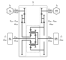
- FIG. FIG. 2 is a skeleton diagram showing the structure of the drive system of the vehicle shown in FIG. 1;
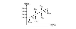
- FIG. 3 is a velocity diagram of the planetary gear mechanism shown in FIG. 2;
- 2 is a block diagram showing the configuration of a vehicle control device shown in FIG. 1;
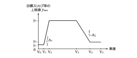
- FIG. FIG. 2 is a map showing the relationship between the vehicle speed and the upper limit set by the limiter in FIG. 1;
- a vehicle control device as an embodiment is applied to a vehicle 1 shown in FIG.
- the vehicle 1 includes left and right wheels 5 (wheels) arranged side by side in the vehicle width direction, a power distribution mechanism 3 (differential mechanism) that imparts a torque difference to the left and right wheels 5, and a pair connected to the power distribution mechanism 3. and a motor 2 of
- alphabetic characters R and L added to numerical symbols indicate the arrangement positions (on the right or left side of the vehicle 1) of the elements corresponding to the symbols.
- 5R represents one of the left and right wheels 5 (that is, the right wheel) positioned on the right side of the vehicle 1
- 5L represents the other (that is, the left wheel) that is positioned on the left side (left).
- the electric motor 2 has the function of driving at least one of the front wheels or the rear wheels of the vehicle 1, and can have the function of driving all four wheels.
- One of the pair of electric motors 2 arranged on the right side is also called a right electric motor 2R (right motor), and the other arranged on the left side is also called a left electric motor 2L (left motor).
- the right electric motor 2R and the left electric motor 2L operate independently of each other and can individually output driving forces of different magnitudes.
- These electric motors 2 are connected to a power distribution mechanism 3 via a pair of speed reduction mechanisms provided separately from each other.
- the right electric motor 2R and the left electric motor 2L of this embodiment have the same rated output and are provided in pairs.
- the vehicle 1 includes a power distribution mechanism 3 that amplifies the torque difference between the pair of electric motors 2 and distributes it to each of the left and right wheels 5 .
- the power distribution mechanism 3 of this embodiment is a differential mechanism having a yaw control function [AYC (Active Yaw Control) function], and the wheel shaft 4 (left wheel shaft 4L) connected to the left wheel 5L and the right wheel 5R It is interposed between the connected wheel axle 4 (right wheel axle 4R).
- the yaw control function is a function for stabilizing the attitude of the vehicle 1 by actively controlling the sharing ratio of the driving force (driving torque) of the left and right wheels 5 to adjust the yaw moment.
- the power distribution mechanism 3 incorporates a planetary gear mechanism, a differential gear mechanism, and the like.
- a vehicle drive system including a pair of electric motors 2 and a power distribution mechanism 3 is also called a DM-AYC (Dual-Motor AYC) system.
- the power distribution mechanism 3 includes a pair of speed reduction mechanisms (gear trains enclosed by dashed lines in FIG. 2) that reduce the rotation speed of the electric motor 2, and a speed change mechanism (indicated by a dashed line in FIG. gear train enclosed).
- the reduction mechanism is a mechanism that increases the torque by reducing the torque (driving force) output from the electric motor 2 .
- the speed reduction ratio of the speed reduction mechanism is appropriately set according to the output characteristics and performance of the electric motor 2 . If the torque performance of the electric motor 2 is sufficiently high, the reduction mechanism may be omitted.
- the transmission mechanism is a mechanism that amplifies the torque difference transmitted to each of the left and right wheels 5 .
- the transmission mechanism of the power distribution mechanism 3 shown in FIG. 2 includes a pair of planetary gear mechanisms. These planetary gear mechanisms have a structure in which the rotation shafts of planetary gears provided on respective carriers are connected to each other. Each carrier rotatably supports the planetary gears and supports the planetary gears so as to revolve between the sun gear and the ring gear. Driving forces transmitted from the left and right electric motors 2 are input to the ring gear and the sun gear of one planetary gear mechanism. The driving force transmitted to the left and right wheels 5 is taken out from the sun gear and carrier of the other planetary gear mechanism. The ring gear of the other planetary gear mechanism is absent.
- the structure of the power distribution mechanism 3 shown in FIG. 2 is merely an example for realizing the yaw control function, and other known structures can be applied.
- Each electric motor 2L, 2R is electrically connected to a battery 7 via an inverter 6 (6L, 6R).
- the inverter 6 is a converter (DC-AC inverter) that mutually converts the power (DC power) of the DC circuit on the battery 7 side and the power (AC power) of the AC circuit on the electric motor 2 side.
- the battery 7 is, for example, a lithium-ion secondary battery or a nickel-hydrogen secondary battery, and is a secondary battery capable of supplying a high-voltage DC current of several hundred volts.
- DC power is converted into AC power by the inverter 6 and supplied to the electric motor 2 .
- the electric motor 2 When the electric motor 2 generates power, the generated power is converted into DC power by the inverter 6 and charged in the battery 7 .
- the operating state of inverter 6 is controlled by vehicle control device 10 .
- the vehicle control device 10 is one of the electronic control units (ECU, Electronic Control Unit) mounted on the vehicle 1 .
- the vehicle control device 10 incorporates a processor (central processing unit), a memory (main memory), a storage device (storage), an interface device, and the like, which are not shown, and these are communicably connected to each other via an internal bus.
- the contents of determinations and controls performed by the vehicle control device 10 are recorded and stored in the memory as firmware and application programs, and when the programs are executed, the contents of the programs are developed in the memory space and executed by the processor. .
- the vehicle control device 10 is connected with an accelerator opening sensor 21, a brake sensor 22, a steering angle sensor 23, a mode selection switch sensor 24, a resolver 25, and a wheel speed sensor 26, as shown in FIG.
- the accelerator opening sensor 21 is a sensor that detects the depression amount (accelerator opening) of the accelerator pedal and the depression speed thereof.
- the brake sensor 22 is a sensor that detects the amount of depression of the brake pedal (brake pedal stroke) and the depression speed thereof.
- the steering angle sensor 23 is a sensor that detects the steering angle of the left and right wheels 5 (actual steering angle or steering angle). , snow mode, tarmac mode, etc.) and a sensor for detecting the operating state of the switch are integrated.
- the resolver 25 is a sensor that detects the rotational angular velocity of the electric motor 2 (that is, the motor angular velocities ⁇ Rm and ⁇ Lm ), and is provided for each electric motor 2 individually.
- the wheel speed sensor 26 is a sensor for detecting the rotational angular velocities (wheel angular velocities ⁇ Rds , ⁇ Lds ) output from the power distribution mechanism 3 to the wheel shafts 4 . is provided in the vicinity of the connection point of The vehicle control device 10 controls the output of the pair of electric motors 2 by controlling the operating state of the inverter 6 based on the information detected by these sensors 21-26.
- the type of sensor that detects the rotational angular velocity of the electric motor 2 is not limited to the resolver 25, and may be another sensor (for example, a Hall sensor or an encoder).
- [2. control model] A control model related to this embodiment will be described.
- braking/driving torque braking torque and driving torque
- V vehicle speed
- F x the braking/driving force
- J w the wheel inertia (moment of inertia)
- ⁇ ds the wheel angular velocity
- T ds the shaft torque (braking/driving torque).
- the effective radius of the tire is r
- the wheel speed is V w
- the slip rate is ⁇ (the slip rate obtained by normalizing the relative speed between the vehicle body speed and the wheel speed), the following equation holds.
- a variable normalized by dividing the longitudinal force by the normal force is called a coefficient of friction ⁇ .
- the relationship between the coefficient of friction ⁇ and the slip ratio ⁇ is nonlinear.
- the value of the coefficient of friction ⁇ takes a maximum value ⁇ max at a predetermined slip ratio (optimal slip ratio ⁇ p0 ).
- the transfer function of the wheel angular velocity with respect to the shaft torque input (the relationship between the input and output expressed as a function of the complex number s) is expressed as follows.
- J n in the following formula is the nominal inertia. That is, when there is a certain slip rate ⁇ n (nominal slip rate), the equivalent inertia of the wheels 5 viewed from the drive side can be considered to be J n .
- FIG. 3 is a velocity diagram regarding the input and output of the power distribution mechanism 3. As shown in FIG. b 1 and b 2 in the figure are equivalent second speed ratios determined by the structure of the gear incorporated in the power distribution mechanism 3 . In this embodiment, the following equation holds.
- T Rin and T Lin are input side torques after gear reduction and coupling, and also include inertia torque on the motor side. Further, T Rm and T Lm are torques after subtracting the inertia torque on the motor side, and can be expressed as follows.
- T RIm and T LIm are inertia torques of the electric motor 2 .
- Im is the inertia of the electric motor 2
- ⁇ Rm and ⁇ Lm are angular velocities on the motor side after the first deceleration.
- the relationship between the motor angular velocities ⁇ Rm , ⁇ Lm and the drive shaft side angular velocities ⁇ Rds , ⁇ Lds is expressed by the following equations.
- FIG. 1 At least a calculation unit 11 , a restriction unit 12 and a control unit 13 are provided inside the vehicle control device 10 .
- the controller 13 includes an FF controller 14 and an FB controller 15 .
- a model calculator 16 and a driving force observer 17 are provided. These elements are shown by classifying the functions of the vehicle control device 10 for convenience. These elements can be described as independent programs, or can be described as a composite program combining multiple elements. A program corresponding to each element is stored in the memory or storage device of the vehicle control device 10 and executed by the processor.
- the calculation unit 11 individually calculates a target slip rate y (slip rate command value), which is a target value of the slip rate ⁇ of the wheels 5R and 5L.
- the value of the target slip ratio y is calculated based on at least the required driving force of the vehicle 1 .
- the value of the target slip ratio y is calculated based on the required driving force of the vehicle 1 and the estimated driving force.
- the target slip ratio y is calculated based on the integrated value (error) obtained by subtracting the estimated driving force from the required driving force.
- the required driving force is calculated based on information detected by the sensors 21-26, for example.
- the definition of the target slip ratio y is shown below.
- This target slip ratio y has the same definition as the slip ratio ⁇ during braking (during deceleration) of the vehicle 1 .
- the relationship between the slip ratio ⁇ and the target slip ratio y during braking is expressed by the following equation. If the slip ratio ⁇ is sufficiently small, both values will be substantially the same.
- the value of the target slip ratio y calculated by the calculation unit 11 is excessive, the value (absolute value) is clipped to a range equal to or less than the upper limit value y max set by the limit unit 12, which will be described later. be. In this case, the value exceeding the upper limit value y max is discarded as a surplus value. Therefore, in order to reflect the value of this surplus in the next and subsequent calculations, a calculation configuration may be adopted in which the surplus value is multiplied by a predetermined gain, introduced again to the upstream side of the calculation unit 11, and subtracted from the required driving force. good.
- the limiting unit 12 individually sets the upper limit value ymax of the target slip ratio y based on at least the vehicle speed V of the vehicle 1, and sets the absolute value
- the target slip ratio y which is limited by the upper limit value y max , also includes a value on the braking side (negative side).
- the vehicle speed V here may be a value calculated based on the wheel angular velocities ⁇ Lds and ⁇ Rds detected by the wheel speed sensor 26, but preferably based on the motor angular velocities ⁇ Rm and ⁇ Lm detected by the resolver 25. It is assumed to be a value calculated by The upper limit value y max functions as a limiter for the target slip ratio y.
- FIG. 5 is a map illustrating the relationship between vehicle speed V and upper limit value y max .
- FIG. 5 shows the limiting characteristics on the driving side (positive side). This map is stored inside the vehicle control device 10 (for example, inside the restriction unit 12 or on a memory accessible by the restriction unit 12).
- the above map includes a first vehicle speed range V1 to V2 , which is a vehicle speed range in which the upper limit value ymax increases as the vehicle speed V increases, and a second vehicle speed range in which the upper limit value ymax decreases as the vehicle speed V increases.
- a region V 3 to V 4 is set.
- the first vehicle speed range V 1 to V 2 means the vehicle speed range from the first vehicle speed V 1 to the second vehicle speed V 2
- the second vehicle speed range V 3 to V 4 means the vehicle speed V from the third vehicle speed. It means the vehicle speed range from V3 to the fourth vehicle speed V4 .
- the magnitude relationship of the values of the vehicle speed V is 0 ⁇ V1 ⁇ V2 ⁇ V3 ⁇ V4 . area.
- the value of the upper limit y max set in the first vehicle speed range V 1 to V 2 has the characteristic of increasing at an upward slope with respect to the increase in vehicle speed V, and the upward slope is A 1 is.
- the value of the upper limit value y max set in the second vehicle speed range V 3 to V 4 has the characteristic of decreasing on the downward slope with respect to the increase of the vehicle speed V, and the downward slope is -A 2 .
- is set to be larger than the absolute value of the descending slope
- the upper limit value y max increases with respect to the increase in vehicle speed V, and the target slip ratio y approaches the optimum slip ratio ⁇ p0 . easier. Also, if the absolute value of the downward slope
- the third vehicle speed range V 0 to V 1 in which the upper limit value y max is set to the first predetermined value y 1 regardless of the vehicle speed V
- a fourth vehicle speed range V 4 to V 5 is set in which max is set to the second predetermined value y 2 .
- the third vehicle speed range V 0 to V 1 means a vehicle speed range in which the vehicle speed V is from the predetermined vehicle speed V 0 to the first vehicle speed V 1
- the fourth vehicle speed range V 4 to V 5 means the vehicle speed V in the fourth vehicle speed V It means the vehicle speed range from 4 to the fifth vehicle speed V5 .
- the magnitude relationship of the value of the vehicle speed V is 0 ⁇ V 0 ⁇ V 1 and V 4 ⁇ V 5 .
- the third vehicle speed range V 0 to V 1 is a vehicle speed range lower than the first vehicle speed range V 1 to V 2
- the fourth vehicle speed range V 4 to V 5 is the second vehicle speed range V 3 to V 4 . It is a vehicle speed range on the higher speed side than .
- the first predetermined value y1 is set to a value smaller than the second predetermined value y2 .
- the upper limit value ymax is the first 3 is set to a predetermined value y3.
- the magnitude relationship of the upper limit value y max is y 1 ⁇ y 2 ⁇ y 3 .
- the slip immediately after the stopped vehicle 1 starts running is strongly restricted. , and the acceleration is likely to increase.
- the third predetermined value y3 is set to a relatively large value (a value larger than the first predetermined value y1 and the second predetermined value y2 )
- the slip ratio at which the frictional force of the wheels 5R and 5L increases It becomes easier to maintain the target slip ratio y within the range of ⁇ , and it becomes easier to increase the driving force.
- the second predetermined value y2 again to a relatively small value (at least a value smaller than the third predetermined value y3 ), occurrence of vibration due to slip and torque suppression in the middle and high speed range is prevented. be. Note that, compared to when the vehicle 1 starts moving, the acceleration is more likely to increase if the target slip ratio y is not excessively limited in the middle and high speed range. That is, by setting the second predetermined value y2 to a value larger than the first predetermined value y1 , not only the damping performance but also the acceleration performance can be improved.
- a parameter other than the vehicle speed V may be reflected in the upper limit value y max .
- the upper limit value y max may be set according to the amount of operation by the driver of the vehicle 1, the vehicle state (lateral acceleration, yaw rate, etc.), and the road surface state.
- the value of the gain X for correcting the upper limit value y max is higher than when the driving mode of the vehicle 1 is the tarmac mode. set smaller.
- the value of the gain X is set to a small value so that the road surface is less slippery.
- the value of the gain X is set large.
- the gain X is a parameter that is multiplied by the upper limit value y max , and is set within a range of 0 or more, for example.
- the value multiplied by the gain X is used as the final upper limit value ymax of the target slip ratio y. With such a setting, the more slippery the road surface is, the stronger the slip is suppressed, so the stability of the vehicle body posture is improved.
- the control unit 13 controls the driving torque of the vehicle 1 for each of the wheels 5R and 5L so that the wheel speed that becomes the target slip ratio y limited by the limiting unit 12 is obtained.
- the control unit 13 is provided with an FF control unit 14 that performs control based on the required driving force, and an FB control unit 15 that performs control based on the target slip ratio y limited by the limit unit 12 .
- the required driving force is multiplied by the effective radius r of the wheels 5R, 5L to be controlled to calculate the required wheel torque for the wheels 5R, 5L.
- Equation 1 If the wheels 5R and 5L stick together, the left side of Equation 1 is sufficiently small, and the shaft torque Tds substantially matches the product rFx of the tire effective radius r and the braking/driving force Fx . Therefore, a drive force approximately equal to the drive force command value can be generated by feedforward, and a slight error is compensated for by the feedback of the drive force control system.
- the FB control unit 15 calculates the torque feedback control amount for the wheels 5R and 5L.
- the sum of the required wheel torque calculated by the FF control unit 14 and the feedback control amount calculated by the FB control unit 15 becomes the final output torque T for the wheels 5R and 5L. Based on this output torque T, the operating state of the pair of electric motors 2 is controlled.
- a calculation method for converting the torque of the wheel shaft 4 into the torque of the electric motor 2 a known method can be applied.
- the FB control unit 15 multiplies the vehicle speed V in the previous calculation cycle by a value obtained by adding 1 to the target slip rate y. Further, the value is divided by the effective radius r of the wheels 5R, 5L to be controlled, and the angular velocity target value ⁇ * of the wheels 5R, 5L is calculated. After that, the torque feedback control amount is adjusted so that the difference between the actual angular velocity ⁇ of the wheels 5R, 5L and the angular velocity target value ⁇ * in the previous calculation cycle becomes small (ideally, the difference becomes 0). (for example, PI control amount) is calculated. Estimated values of the vehicle speed V and the angular velocity ⁇ calculated by the model calculator 16 may be used instead of the vehicle speed V and the angular speed ⁇ in the previous calculation cycle.
- the wheel speed control is PI (proportional integral) control
- its proportional gain K p and integral gain K i are expressed as follows.
- the model calculation unit 16 calculates estimated values of the vehicle speed, wheel speed, vehicle body acceleration, etc. when the wheels 5R and 5L are driven with the output torque T based on a predetermined vehicle model. These estimated values can be derived, for example, by applying a known arithmetic method for converting the torque of the electric motor 2 into the torque of the wheel shaft 4 .
- the driving force observer unit 17 calculates an estimated driving force based on at least the output torque T.
- the inertia torque Jws of each of the left and right wheels 5 is calculated based on the wheel speed calculated by the model calculation unit 16, for example.
- an estimated shaft torque is calculated by subtracting the inertia torque J ws from the output torque T.
- the estimated driving force is calculated by dividing this estimated shaft torque by the effective radius r of the wheels 5R and 5L.
- the above inertia torque J ws can also be calculated from the detected value of the resolver 25 .
- the wheel speeds of the left and right wheels 5 (angular velocities ⁇ Rds , ⁇ Lds on the drive shaft side) are estimated from the motor angular velocities ⁇ Rm , ⁇ Lm detected by the resolver 25 based on Equation 8 above.
- the inertia torque Jws of each of the left and right wheels 5 corresponds to the second term on the right side of Equation 10 and the second term on the right side of Equation 11, and thus can be calculated from each wheel speed.
- the estimated driving force is calculated by dividing the estimated shaft torque obtained by subtracting the inertia torque Jws from the output torque T by the effective radius r of the wheels 5R and 5L.
- the vehicle control device 10 is provided with the calculation section 11 , the restriction section 12 and the control section 13 .
- the calculation unit 11 calculates a target slip ratio y, which is a target value of the slip ratio ⁇ of the wheels 5R and 5L.
- the limiting unit 12 sets an upper limit value y max of the target slip ratio y based on at least the vehicle speed V of the vehicle 1, and limits the target slip ratio y calculated by the calculating unit 11 to be equal to or lower than the upper limit value y max .
- the control unit 13 controls the driving torque of the vehicle 1 so that the wheel speed that becomes the target slip ratio y limited by the limiting unit 12 is obtained.
- the target slip ratio y can be brought closer to the optimum value according to the vehicle speed V, and the running performance and stability of the vehicle 1 can be improved.
- the value of the upper limit value y max is fixed, it is possible to properly use the speed range in which the wheels 5L and 5R are allowed to slip and the speed range in which the slip is restricted.
- Driving performance and stability of the vehicle 1 can be improved.
- the limiting unit 12 can set the upper limit value y max according to the amount of operation by the driver of the vehicle 1, the vehicle state (lateral acceleration, yaw rate, etc.), and the road surface state. For example, by setting the upper limit value y max according to the driving mode selected by the mode selection switch sensor 24, the driving performance and stability of the vehicle 1 can be further improved. Further, when the road surface is slippery or when the acceleration/deceleration acting on the vehicle 1 is large, by reducing the upper limit value y max , it is possible to strongly suppress the slip and improve the stability of the vehicle body posture.
- the target slip ratio y can be brought closer to the optimum slip ratio ⁇ p0 , thereby improving the running performance of the vehicle 1. can be improved.
- the computing unit 11 can compute the target slip ratio y based on the required driving force of the vehicle 1 and the estimated driving force. With such a configuration, it is possible to improve the responsiveness of the feedback, and to accurately control the target slip ratio y. Therefore, the running performance and stability of the vehicle 1 can be improved.
- the limiting unit 12 can set the upper limit value y max of the target slip ratio y for each of the left and right wheels 5 using the rotational angular velocities of the electric motor 2 (motor angular velocities ⁇ Rm and ⁇ Lm ). .
- the response of the target slip ratio y is lower than in the case where the upper limit value y max is set using the vehicle speed V based on the detection values (wheel angular velocities ⁇ Lds , ⁇ Rds ) of the wheel speed sensors 26, for example. performance and controllability can be improved. Therefore, the running performance and stability of the vehicle 1 can be improved.
- the map that defines the relationship between the vehicle speed V and the upper limit value y max includes a first vehicle speed region V 1 to V2 , and a second vehicle speed range V3 to V4 , which is a higher vehicle speed range than the first vehicle speed range V1 to V2 and in which the upper limit value ymax decreases as the vehicle speed V increases.
- in the first vehicle speed range V 1 to V 2 is set larger than the absolute value of the falling slope
- the target slip ratio y in the low speed range can be brought closer to the optimum slip ratio ⁇ p0 at an early stage, and the running performance of the vehicle 1 can be improved.
- the upper limit value y max is set to the first predetermined value y 1 irrespective of the magnitude of the vehicle speed V in the vehicle speed range lower than the first vehicle speed range V 1 to V 2 .
- a fourth vehicle speed range V 4 to V 5 to be set is set.
- the first predetermined value y1 is set smaller than the second predetermined value y2 .
- the vehicle control device 10 applied to the rear wheels of the vehicle 1 was illustrated, but a similar vehicle control device may be applied to the front wheels, or a similar vehicle control device may be applied to both the front and rear wheels. may apply.
- a similar vehicle control device may be applied to both the front and rear wheels.
- vehicle 2 electric motor 3 power distribution mechanism (differential mechanism) 4 Wheel shaft 5 Left and right wheels (wheels) 6 inverter 7 battery 10 vehicle control unit (ECU) 11 calculation unit 12 restriction unit 13 control unit 14 FF control unit 15 FB control unit 16 model calculation unit 17 driving force observer unit 21 accelerator opening sensor 22 brake sensor 23 steering angle sensor 24 mode selection switch sensor 25 resolver 26 wheel speed sensor ⁇ slip ratio ⁇ p0 optimal slip ratio y Target slip ratio y max upper limit
Landscapes
- Engineering & Computer Science (AREA)
- Transportation (AREA)
- Mechanical Engineering (AREA)
- Power Engineering (AREA)
- Chemical & Material Sciences (AREA)
- Combustion & Propulsion (AREA)
- Life Sciences & Earth Sciences (AREA)
- Sustainable Development (AREA)
- Sustainable Energy (AREA)
- Automation & Control Theory (AREA)
- Electric Propulsion And Braking For Vehicles (AREA)
Abstract
Priority Applications (4)
| Application Number | Priority Date | Filing Date | Title |
|---|---|---|---|
| JP2023540321A JP7540659B2 (ja) | 2021-08-06 | 2022-08-01 | 車両制御装置 |
| EP22852984.8A EP4382346A1 (fr) | 2021-08-06 | 2022-08-01 | Dispositif de commande de véhicule |
| US18/566,933 US20240270084A1 (en) | 2021-08-06 | 2022-08-01 | Vehicle control device |
| CN202280036647.2A CN117677528A (zh) | 2021-08-06 | 2022-08-01 | 车辆控制装置 |
Applications Claiming Priority (2)
| Application Number | Priority Date | Filing Date | Title |
|---|---|---|---|
| JP2021129862 | 2021-08-06 | ||
| JP2021-129862 | 2021-08-06 |
Publications (1)
| Publication Number | Publication Date |
|---|---|
| WO2023013565A1 true WO2023013565A1 (fr) | 2023-02-09 |
Family
ID=85154765
Family Applications (1)
| Application Number | Title | Priority Date | Filing Date |
|---|---|---|---|
| PCT/JP2022/029414 WO2023013565A1 (fr) | 2021-08-06 | 2022-08-01 | Dispositif de commande de véhicule |
Country Status (5)
| Country | Link |
|---|---|
| US (1) | US20240270084A1 (fr) |
| EP (1) | EP4382346A1 (fr) |
| JP (1) | JP7540659B2 (fr) |
| CN (1) | CN117677528A (fr) |
| WO (1) | WO2023013565A1 (fr) |
Cited By (1)
| Publication number | Priority date | Publication date | Assignee | Title |
|---|---|---|---|---|
| CN116278814A (zh) * | 2023-05-19 | 2023-06-23 | 成都赛力斯科技有限公司 | 基于滑移率的汽车稳定性控制方法、装置及新能源汽车 |
Citations (4)
| Publication number | Priority date | Publication date | Assignee | Title |
|---|---|---|---|---|
| JPH0725327A (ja) * | 1993-07-09 | 1995-01-27 | Mazda Motor Corp | 車両の制御装置 |
| JP2005124399A (ja) * | 1999-10-08 | 2005-05-12 | Toyota Motor Corp | 4輪駆動車の制御装置 |
| JP2006136173A (ja) * | 2004-11-09 | 2006-05-25 | Nissan Motor Co Ltd | 車両のモータトラクション制御装置 |
| JP2009065793A (ja) | 2007-09-07 | 2009-03-26 | Bridgestone Corp | 電動車両 |
-
2022
- 2022-08-01 US US18/566,933 patent/US20240270084A1/en active Pending
- 2022-08-01 EP EP22852984.8A patent/EP4382346A1/fr active Pending
- 2022-08-01 JP JP2023540321A patent/JP7540659B2/ja active Active
- 2022-08-01 WO PCT/JP2022/029414 patent/WO2023013565A1/fr active Application Filing
- 2022-08-01 CN CN202280036647.2A patent/CN117677528A/zh active Pending
Patent Citations (4)
| Publication number | Priority date | Publication date | Assignee | Title |
|---|---|---|---|---|
| JPH0725327A (ja) * | 1993-07-09 | 1995-01-27 | Mazda Motor Corp | 車両の制御装置 |
| JP2005124399A (ja) * | 1999-10-08 | 2005-05-12 | Toyota Motor Corp | 4輪駆動車の制御装置 |
| JP2006136173A (ja) * | 2004-11-09 | 2006-05-25 | Nissan Motor Co Ltd | 車両のモータトラクション制御装置 |
| JP2009065793A (ja) | 2007-09-07 | 2009-03-26 | Bridgestone Corp | 電動車両 |
Non-Patent Citations (3)
| Title |
|---|
| HIROSHI FUJIMOTOJUNYA AMADATAKAYUKI MIYAJIMA: "Summarized Papers of technical sessions", 2013, 2013 JSAE ANNUAL CONGRESS (SPRING, article "Development and Control of Electric Vehicle with Variable Drive Unit system", pages: 17 - 20 |
| HIROSHI FUJIMOTOTAKESHI TAKANOHIDETOSHI NOBUMOTOTOSHIMI OKAZAKI: "Driving Force Control Method Based on High Accuracy Slip Ratio Control", MAZDA TECHNICAL REVIEW, vol. 32, 2015, pages 228 - 233 |
| MASATAKA YOSHIMURAHIROSHI FUJIMOTO: "Driving Torque Control Method for Electric Vehicle with In-Wheel Motors", vol. 131, 2011, THE TRANSACTIONS OF THE INSTITUTE OF ELECTRICAL ENGINEERS OF JAPAN, D, pages: 721 - 728 |
Cited By (2)
| Publication number | Priority date | Publication date | Assignee | Title |
|---|---|---|---|---|
| CN116278814A (zh) * | 2023-05-19 | 2023-06-23 | 成都赛力斯科技有限公司 | 基于滑移率的汽车稳定性控制方法、装置及新能源汽车 |
| CN116278814B (zh) * | 2023-05-19 | 2023-07-21 | 成都赛力斯科技有限公司 | 基于滑移率的汽车稳定性控制方法、装置及新能源汽车 |
Also Published As
| Publication number | Publication date |
|---|---|
| EP4382346A1 (fr) | 2024-06-12 |
| JPWO2023013565A1 (fr) | 2023-02-09 |
| CN117677528A (zh) | 2024-03-08 |
| JP7540659B2 (ja) | 2024-08-27 |
| US20240270084A1 (en) | 2024-08-15 |
Similar Documents
| Publication | Publication Date | Title |
|---|---|---|
| US10093308B2 (en) | Electronic stability control system for vehicle | |
| US6945347B2 (en) | Drive power controller for hybrid vehicle | |
| US8521349B2 (en) | Vehicle steerability and stability control via independent wheel torque control | |
| JP2010273540A (ja) | 回生制動を持つ車両の独立制動及び操縦性の制御方法及びシステム | |
| US20050103549A1 (en) | Vehicle driving force control apparatus | |
| EP4019318A1 (fr) | Dispositif de commande de véhicule | |
| JP4844320B2 (ja) | ハイブリッド車両の駆動力制御装置 | |
| KR20240053087A (ko) | 차량의 트랙션 제어 방법 | |
| WO2023013565A1 (fr) | Dispositif de commande de véhicule | |
| WO2023013566A1 (fr) | Dispositif de commande de véhicule | |
| JP4961751B2 (ja) | 車両の駆動力配分装置 | |
| WO2015019399A1 (fr) | Dispositif de commande de suppression des vibrations de véhicule | |
| JP2022057096A (ja) | 車両の制御装置 | |
| WO2016125686A1 (fr) | Dispositif de commande de couple de freinage/entraînement de véhicule | |
| JP7480661B2 (ja) | 車両の制御装置 | |
| US20240317205A1 (en) | Vehicle control device | |
| JP7380911B2 (ja) | 車両の制御装置 | |
| JP4165344B2 (ja) | 車両の制御装置 | |
| WO2022070732A1 (fr) | Dispositif de commande de véhicule | |
| WO2024038711A1 (fr) | Dispositif de commande de véhicule et procédé de commande de véhicule | |
| CN113573941B (zh) | 车辆控制装置 | |
| WO2022024753A1 (fr) | Dispositif de commande d'entraînement pour véhicule électrique | |
| WO2023032012A1 (fr) | Procédé de commande pour véhicule à moteur électrique et dispositif de commande pour véhicule à moteur électrique | |
| WO2023182209A1 (fr) | Dispositif de commande de déplacement pour véhicule | |
| JP2020043668A (ja) | 車両運動制御装置およびこの車両運動制御装置を備えた車両 |
Legal Events
| Date | Code | Title | Description |
|---|---|---|---|
| 121 | Ep: the epo has been informed by wipo that ep was designated in this application |
Ref document number: 22852984 Country of ref document: EP Kind code of ref document: A1 |
|
| WWE | Wipo information: entry into national phase |
Ref document number: 2023540321 Country of ref document: JP |
|
| WWE | Wipo information: entry into national phase |
Ref document number: 202280036647.2 Country of ref document: CN |
|
| WWE | Wipo information: entry into national phase |
Ref document number: 18566933 Country of ref document: US |
|
| NENP | Non-entry into the national phase |
Ref country code: DE |
|
| ENP | Entry into the national phase |
Ref document number: 2022852984 Country of ref document: EP Effective date: 20240306 |