WO2023007939A1 - 負極材料、負極および電池及びそれらの製造方法 - Google Patents
負極材料、負極および電池及びそれらの製造方法 Download PDFInfo
- Publication number
- WO2023007939A1 WO2023007939A1 PCT/JP2022/021998 JP2022021998W WO2023007939A1 WO 2023007939 A1 WO2023007939 A1 WO 2023007939A1 JP 2022021998 W JP2022021998 W JP 2022021998W WO 2023007939 A1 WO2023007939 A1 WO 2023007939A1
- Authority
- WO
- WIPO (PCT)
- Prior art keywords
- negative electrode
- solid electrolyte
- composite particles
- particles
- active material
- Prior art date
- Legal status (The legal status is an assumption and is not a legal conclusion. Google has not performed a legal analysis and makes no representation as to the accuracy of the status listed.)
- Ceased
Links
Images


Classifications
-
- H—ELECTRICITY
- H01—ELECTRIC ELEMENTS
- H01M—PROCESSES OR MEANS, e.g. BATTERIES, FOR THE DIRECT CONVERSION OF CHEMICAL ENERGY INTO ELECTRICAL ENERGY
- H01M4/00—Electrodes
- H01M4/02—Electrodes composed of, or comprising, active material
- H01M4/13—Electrodes for accumulators with non-aqueous electrolyte, e.g. for lithium-accumulators; Processes of manufacture thereof
- H01M4/134—Electrodes based on metals, Si or alloys
-
- H—ELECTRICITY
- H01—ELECTRIC ELEMENTS
- H01M—PROCESSES OR MEANS, e.g. BATTERIES, FOR THE DIRECT CONVERSION OF CHEMICAL ENERGY INTO ELECTRICAL ENERGY
- H01M10/00—Secondary cells; Manufacture thereof
- H01M10/05—Accumulators with non-aqueous electrolyte
- H01M10/052—Li-accumulators
-
- H—ELECTRICITY
- H01—ELECTRIC ELEMENTS
- H01M—PROCESSES OR MEANS, e.g. BATTERIES, FOR THE DIRECT CONVERSION OF CHEMICAL ENERGY INTO ELECTRICAL ENERGY
- H01M10/00—Secondary cells; Manufacture thereof
- H01M10/05—Accumulators with non-aqueous electrolyte
- H01M10/056—Accumulators with non-aqueous electrolyte characterised by the materials used as electrolytes, e.g. mixed inorganic/organic electrolytes
- H01M10/0561—Accumulators with non-aqueous electrolyte characterised by the materials used as electrolytes, e.g. mixed inorganic/organic electrolytes the electrolyte being constituted of inorganic materials only
- H01M10/0562—Solid materials
-
- H—ELECTRICITY
- H01—ELECTRIC ELEMENTS
- H01M—PROCESSES OR MEANS, e.g. BATTERIES, FOR THE DIRECT CONVERSION OF CHEMICAL ENERGY INTO ELECTRICAL ENERGY
- H01M4/00—Electrodes
- H01M4/02—Electrodes composed of, or comprising, active material
- H01M4/13—Electrodes for accumulators with non-aqueous electrolyte, e.g. for lithium-accumulators; Processes of manufacture thereof
- H01M4/133—Electrodes based on carbonaceous material, e.g. graphite-intercalation compounds or CFx
-
- H—ELECTRICITY
- H01—ELECTRIC ELEMENTS
- H01M—PROCESSES OR MEANS, e.g. BATTERIES, FOR THE DIRECT CONVERSION OF CHEMICAL ENERGY INTO ELECTRICAL ENERGY
- H01M4/00—Electrodes
- H01M4/02—Electrodes composed of, or comprising, active material
- H01M4/13—Electrodes for accumulators with non-aqueous electrolyte, e.g. for lithium-accumulators; Processes of manufacture thereof
- H01M4/139—Processes of manufacture
- H01M4/1395—Processes of manufacture of electrodes based on metals, Si or alloys
-
- H—ELECTRICITY
- H01—ELECTRIC ELEMENTS
- H01M—PROCESSES OR MEANS, e.g. BATTERIES, FOR THE DIRECT CONVERSION OF CHEMICAL ENERGY INTO ELECTRICAL ENERGY
- H01M4/00—Electrodes
- H01M4/02—Electrodes composed of, or comprising, active material
- H01M4/36—Selection of substances as active materials, active masses, active liquids
-
- H—ELECTRICITY
- H01—ELECTRIC ELEMENTS
- H01M—PROCESSES OR MEANS, e.g. BATTERIES, FOR THE DIRECT CONVERSION OF CHEMICAL ENERGY INTO ELECTRICAL ENERGY
- H01M4/00—Electrodes
- H01M4/02—Electrodes composed of, or comprising, active material
- H01M4/36—Selection of substances as active materials, active masses, active liquids
- H01M4/362—Composites
- H01M4/364—Composites as mixtures
-
- H—ELECTRICITY
- H01—ELECTRIC ELEMENTS
- H01M—PROCESSES OR MEANS, e.g. BATTERIES, FOR THE DIRECT CONVERSION OF CHEMICAL ENERGY INTO ELECTRICAL ENERGY
- H01M4/00—Electrodes
- H01M4/02—Electrodes composed of, or comprising, active material
- H01M4/36—Selection of substances as active materials, active masses, active liquids
- H01M4/38—Selection of substances as active materials, active masses, active liquids of elements or alloys
- H01M4/386—Silicon or alloys based on silicon
-
- H—ELECTRICITY
- H01—ELECTRIC ELEMENTS
- H01M—PROCESSES OR MEANS, e.g. BATTERIES, FOR THE DIRECT CONVERSION OF CHEMICAL ENERGY INTO ELECTRICAL ENERGY
- H01M4/00—Electrodes
- H01M4/02—Electrodes composed of, or comprising, active material
- H01M4/62—Selection of inactive substances as ingredients for active masses, e.g. binders, fillers
-
- H—ELECTRICITY
- H01—ELECTRIC ELEMENTS
- H01M—PROCESSES OR MEANS, e.g. BATTERIES, FOR THE DIRECT CONVERSION OF CHEMICAL ENERGY INTO ELECTRICAL ENERGY
- H01M4/00—Electrodes
- H01M4/02—Electrodes composed of, or comprising, active material
- H01M4/62—Selection of inactive substances as ingredients for active masses, e.g. binders, fillers
- H01M4/624—Electric conductive fillers
- H01M4/625—Carbon or graphite
-
- H—ELECTRICITY
- H01—ELECTRIC ELEMENTS
- H01M—PROCESSES OR MEANS, e.g. BATTERIES, FOR THE DIRECT CONVERSION OF CHEMICAL ENERGY INTO ELECTRICAL ENERGY
- H01M4/00—Electrodes
- H01M4/02—Electrodes composed of, or comprising, active material
- H01M2004/021—Physical characteristics, e.g. porosity, surface area
-
- H—ELECTRICITY
- H01—ELECTRIC ELEMENTS
- H01M—PROCESSES OR MEANS, e.g. BATTERIES, FOR THE DIRECT CONVERSION OF CHEMICAL ENERGY INTO ELECTRICAL ENERGY
- H01M4/00—Electrodes
- H01M4/02—Electrodes composed of, or comprising, active material
- H01M2004/026—Electrodes composed of, or comprising, active material characterised by the polarity
- H01M2004/027—Negative electrodes
-
- H—ELECTRICITY
- H01—ELECTRIC ELEMENTS
- H01M—PROCESSES OR MEANS, e.g. BATTERIES, FOR THE DIRECT CONVERSION OF CHEMICAL ENERGY INTO ELECTRICAL ENERGY
- H01M2300/00—Electrolytes
- H01M2300/0017—Non-aqueous electrolytes
- H01M2300/0065—Solid electrolytes
- H01M2300/0068—Solid electrolytes inorganic
-
- Y—GENERAL TAGGING OF NEW TECHNOLOGICAL DEVELOPMENTS; GENERAL TAGGING OF CROSS-SECTIONAL TECHNOLOGIES SPANNING OVER SEVERAL SECTIONS OF THE IPC; TECHNICAL SUBJECTS COVERED BY FORMER USPC CROSS-REFERENCE ART COLLECTIONS [XRACs] AND DIGESTS
- Y02—TECHNOLOGIES OR APPLICATIONS FOR MITIGATION OR ADAPTATION AGAINST CLIMATE CHANGE
- Y02E—REDUCTION OF GREENHOUSE GAS [GHG] EMISSIONS, RELATED TO ENERGY GENERATION, TRANSMISSION OR DISTRIBUTION
- Y02E60/00—Enabling technologies; Technologies with a potential or indirect contribution to GHG emissions mitigation
- Y02E60/10—Energy storage using batteries
Definitions
- the present disclosure relates to negative electrode materials, negative electrodes, batteries, and methods of manufacturing them.
- An all-solid secondary battery has, for example, a positive electrode, a negative electrode, and a solid electrolyte layer.
- An all-solid secondary battery uses a solid electrolyte as a medium for conducting lithium ions.
- Patent Documents 1 to 3 disclose non-aqueous electrolyte batteries using a negative electrode containing a solid electrolyte.
- This disclosure is a plurality of composite particles including an active material containing silicon, a first solid electrolyte, and a first conductive material; a second solid electrolyte; with The second solid electrolyte is present between the composite particles, A negative electrode material is provided.
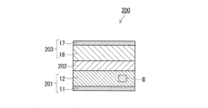
- FIG. 1 is a cross-sectional view showing a schematic configuration of a battery according to an embodiment.
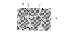
- FIG. 2 is a partially enlarged view of FIG. 1 showing a schematic configuration of the negative electrode active material layer.
- FIG. 3 is a schematic cross-sectional view of composite particles.
- FIG. 4 is a schematic cross-sectional view showing the local structure of the negative electrode.
- FIG. 5 is a process drawing showing a method of manufacturing a negative electrode.
- Graphite has been conventionally used as an active material for non-aqueous electrolyte secondary batteries.
- silicon has been proposed as a negative electrode active material in order to improve the energy density of non-aqueous electrolyte secondary batteries.
- Silicon is one of the materials that can form alloys with lithium.
- the capacity per unit mass of silicon is greater than the capacity per unit mass of graphite.
- silicon greatly expands and contracts with charging and discharging. Therefore, in a battery using silicon as a negative electrode active material, there is a problem that the cycle characteristics tend to deteriorate due to poor contact between the particles of the active material and poor contact between the particles of the active material and the current collector.
- Patent Document 1 discloses that when silicon particles with an average particle size of 0.19 ⁇ m are used, the volume change of the battery due to charging and discharging is reduced as compared with the case of using silicon particles with an average particle size of 2.6 ⁇ m. disclosed.
- Silicon particles with a small average particle size are advantageous in suppressing deterioration of the negative electrode due to volume change.
- silicon particles with a small average particle size have a narrow ion conduction path between silicon particles due to the solid electrolyte, poor connectivity between the particles of the solid electrolyte, and silicon particles and the solid electrolyte. make it difficult to secure a contact surface with
- the average particle size of the particles of the solid electrolyte must also be small. This also causes other problems such as complication of the manufacturing method of the solid electrolyte and reduction in the strength of the negative electrode.
- the present inventors have extensively studied techniques for improving the ionic conductivity of a negative electrode material containing a silicon-containing active material and a solid electrolyte. As a result, the present disclosure has been conceived.
- the negative electrode material according to the first aspect of the present disclosure is a plurality of composite particles including an active material containing silicon, a first solid electrolyte, and a first conductive material; a second solid electrolyte; with The second solid electrolyte exists between the composite particles.
- the ion conductivity of the negative electrode material containing the active material containing silicon and the solid electrolyte can be improved.
- the second solid electrolyte may have the same chemical composition as the chemical composition of the first solid electrolyte. With such a configuration, the ion conductivity of the solid electrolyte portion in the negative electrode is improved.
- the second solid electrolyte may have a chemical composition different from that of the first solid electrolyte. According to such a configuration, there is a possibility that the input/output characteristics of the battery can be further improved as compared with the case where solid electrolytes of the same composition are used.
- the plurality of composite particles may have an average particle diameter of 3 ⁇ m or more and 12 ⁇ m or less.
- the connectivity of the second fixed electrolyte filled between the composite particles is improved, and the ionic conductivity of the solid electrolyte portion in the negative electrode is improved. do.
- the active material containing silicon may have a particle shape, and the active material containing silicon may have a particle shape.
- the particles of matter may have an average particle size of 1 ⁇ m or less. Particles of an active material containing silicon having a small average particle size are advantageous from the viewpoint of suppressing changes in volume of a battery due to charging and discharging.
- the first solid electrolyte may have a particle shape, and the first solid electrolyte The average particle size of the particles may be 1 ⁇ m or less. When the first solid electrolyte has an appropriate average particle size, the first solid electrolyte is less likely to be split inside the composite particles.
- the second solid electrolyte may have a particle shape, and the second solid electrolyte The average particle size of the particles may be 1 ⁇ m or less.
- the second solid electrolyte has an appropriate average particle size, the second solid electrolyte filled between the composite particles is less likely to split.
- the first conductive material may contain a first carbon material.
- a carbon material is suitable for the first conductive material because it is lightweight and chemically stable.
- the first carbon material may contain carbon fiber. According to such a configuration, it is possible to effectively increase the electron conductivity inside the composite particles.
- the average fiber diameter of the carbon fibers may be 0.2 ⁇ m or less. According to such a configuration, the first carbon material is less likely to block the ion conduction path inside the composite particle.
- the negative electrode material according to any one of the first to tenth aspects may further include a second conductive material, and the second conductive material is the composite particles and It may exist between the composite particles. According to such a configuration, it is possible to further increase the electron conductivity inside the negative electrode and between the composite particles.
- the second conductive material may contain a second carbon material.
- a carbon material is suitable for the second conductive material because it is lightweight and chemically stable.
- the negative electrode according to the thirteenth aspect of the present disclosure is a negative electrode current collector; a negative electrode active material layer supported by the negative electrode current collector; with The negative electrode active material layer includes the negative electrode material of any one of the first to twelfth aspects.
- a negative electrode with excellent ion conductivity is obtained.
- the second solid electrolyte in the cross section of the negative electrode, may have a plurality of crushed phases, and the first solid electrolyte may have a plurality of phases distributed inside the plurality of composite particles, and the plurality of phases of the first solid electrolyte and the phases of the second solid electrolyte contained in the plurality of composite particles A plurality of phases may not show orientation in a specific direction. With such a configuration, the ionic conductivity of the negative electrode can be improved.
- the battery according to the fifteenth aspect of the present disclosure includes a positive electrode; the negative electrode of the thirteenth or fourteenth aspect; a solid electrolyte layer disposed between the positive electrode and the negative electrode; Prepare.
- a battery with excellent input/output characteristics can be obtained.
- a method for producing a negative electrode material according to the sixteenth aspect of the present disclosure includes: a plurality of composite particles including an active material containing silicon, a first solid electrolyte, and a first conductive material; a second solid electrolyte; and mixing The second solid electrolyte exists between the composite particles.
- the active material containing silicon, the first solid electrolyte, and the first conductive material are mixed to form the composite particles. Further comprising the step of fabricating.
- the negative electrode material manufactured by the method for manufacturing a negative electrode material according to the sixteenth aspect or the seventeenth aspect is molded.
- a method for manufacturing a battery according to the nineteenth aspect of the present disclosure for example, laminates a negative electrode manufactured by the method for manufacturing a negative electrode according to the eighteenth aspect, an electrolyte layer, and a positive electrode.
- FIG. 1 is a cross-sectional view showing a schematic configuration of a battery 200 according to an embodiment.
- Battery 200 includes negative electrode 201 , solid electrolyte layer 202 , and positive electrode 203 .
- Solid electrolyte layer 202 is arranged between negative electrode 201 and positive electrode 203 .
- the negative electrode 201 absorbs and releases lithium as it is charged and discharged.
- the positive electrode 203 also absorbs and releases lithium as it is charged and discharged.
- Negative electrode 201 has negative electrode current collector 11 and negative electrode active material layer 12 .
- the negative electrode active material layer 12 is supported by the negative electrode current collector 11 .
- the negative electrode current collector 11 and the negative electrode active material layer 12 are in contact with each other.
- a negative electrode active material layer 12 is arranged between the negative electrode current collector 11 and the solid electrolyte layer 202 .
- the negative electrode current collector 11 is made of a conductive material such as a metal material or a carbon material.
- the thickness of the negative electrode 201 may be 10 ⁇ m or more and 500 ⁇ m or less. When the thickness of the negative electrode 201 is 10 ⁇ m or more, the energy density of the battery 200 is sufficiently ensured. When the thickness of the negative electrode 201 is 500 ⁇ m or less, the battery 200 can operate at high output.
- FIG. 2 is a partially enlarged view of FIG. 1 showing a schematic configuration of the negative electrode active material layer 12.
- the negative electrode active material layer 12 includes a plurality of composite particles 21, a second solid electrolyte 22, and a second conductive material 23 as negative electrode materials.
- the second solid electrolyte 22 exists between composite particles 21 and 21 .
- the second solid electrolyte 22 may have the shape of particles. Particles of the second solid electrolyte 22 are connected to each other to form an ion conducting path inside the negative electrode active material layer 12 .
- the second conductive material 23 may have the shape of particles. Particles of the second conductive material 23 are connected to each other to form an electron conduction path inside the negative electrode active material layer 12 .
- FIG. 3 is a schematic cross-sectional view of composite particles 21.
- composite particle 21 includes silicon 31 , first solid electrolyte 32 , and first conductive material 33 .
- silicon 31, first solid electrolyte 32, and first conductive material 33 may each have a particle shape, or may not have a distinct particle shape.
- the phase of silicon 31 and the phase of first solid electrolyte 32 may be mixed.
- the first conductive material 33 appears, for example, as a plurality of spotted regions in the cross section of the composite particle 21 .
- the silicon 31 is incorporated into the composite particles 21.
- the particle diameter of composite particle 21 is larger than the particle diameter of silicon 31 inside composite particle 21 . Therefore, for example, even when a solid electrolyte having a particle diameter larger than that of the silicon 31 is used as the second solid electrolyte 22, the second solid electrolyte 22 is densely filled between the composite particles 21 and the composite particles 21. , the voids between the composite particles 21 can be reduced. As a result, the second solid electrolyte 22 is connected to substantially the entire interior of the negative electrode active material layer 12, and the ion conductivity of the solid electrolyte portion within the negative electrode active material layer 12 is improved. At the same time, the contact surface between composite particles 21 and second solid electrolyte 22 also increases.
- the first solid electrolyte 32 contained in the composite particle 21 becomes an ion conduction path branching from the second solid electrolyte 22 filled around the composite particle 21 inside the composite particle 21, and the silicon 31 and the second solid electrolyte 22 to increase the contact surface.
- the first conductive material 33 contained in the composite particles 21 enhances the electronic conductivity inside the composite particles 21 and also enhances the electronic conductivity between the composite particles 21 .
- the negative electrode active material layer 12 also contains the second conductive material 23 .
- the second conductive material 23 also has the shape of particles. Particles of the second conductive material 23 are dispersed in the negative electrode active material layer 12 .
- the second conductive material 23 exists between the composite particles 21 and the composite particles 21 .
- the second conductive material 23 also contributes to reducing voids between composite particles 21 .
- the composite particles 21 are particles granulated from silicon 31 powder, first solid electrolyte 32 powder, and first conductive material 33 powder.
- the composite particles 21 may be secondary particles.
- a binder may be used for granulation of the composite particles 21 .
- the composite particle 21 may be a sintered body of each material.
- small particles of silicon 31 can aggregate to form relatively large phases of silicon 31 .
- small particles of the first solid electrolyte 32 may aggregate to form a relatively large phase of the first solid electrolyte 32 .
- a plurality of phases of silicon 31 and a plurality of phases of first solid electrolyte 32 are mixed to form one composite particle 21 .
- the phase of silicon 31 and the phase of first solid electrolyte 32 may be exposed on the surface of composite particle 21 .
- the average particle diameter of the composite particles 21 is, for example, 3 ⁇ m or more and 12 ⁇ m or less.
- the connectivity of the second solid electrolyte 22 filled between the composite particles 21 is improved, and the solid electrolyte portion in the negative electrode 201 is reduced.
- the contact surface between the silicon 31 and the first solid electrolyte 32 is sufficiently secured inside the composite particles 21, the battery 200 having excellent input/output characteristics can be obtained.
- the average particle size of various particles can be calculated by the following method.
- a cross section of a structure containing particles is observed with an electron microscope, and the area of a specific particle in the microscopic image is calculated by image processing.
- the diameter of a circle with an area equal to the calculated area is taken as the diameter of that particular particle.
- An arbitrary number (for example, 10) of particles is calculated and their average value is regarded as the average particle size of the particles.
- silicon 31 forming the composite particles 21 for example, silicon with a purity of 99% or more can be used. Silicon 31 may be monocrystalline, polycrystalline, or amorphous.
- the silicon 31 may have a particle shape.
- the average particle diameter of the particles of silicon 31 is, for example, 1 ⁇ m or less. Particles of silicon 31 having a small average particle size are advantageous from the viewpoint of suppressing volume change of battery 200 due to charging and discharging.
- the lower limit of the average particle size of the particles of silicon 31 is not particularly limited, and is, for example, 0.1 ⁇ m. It is assumed that particles of silicon 31 are aggregated inside composite particles 21 . Therefore, the particles of silicon 31 observed in the cross section of composite particles 21 are considered to have a size exceeding the particle size of the silicon powder used for granulation of composite particles 21 .
- the first solid electrolyte 32 is a solid electrolyte having lithium ion conductivity.
- solid electrolytes that can be used for the first solid electrolyte 32 include the materials that can be used for the solid electrolyte layer 202, which will be described later.
- the dense composite particles 21 can be obtained by a simple process such as press molding at 100° C. or less.
- the first solid electrolyte 32 may have a particle shape.
- the average particle size of the particles of the first solid electrolyte 32 is, for example, 1 ⁇ m or less.
- the division of the first solid electrolyte 32 inside the composite particle 21 is less likely to occur.
- the contact surfaces between the first solid electrolyte 32 and the silicon 31 are more likely to come into contact with the second solid electrolyte 22 outside the composite particles 21 .
- the lower limit of the average particle size of the particles of the first solid electrolyte 32 is not particularly limited, and is, for example, 0.1 ⁇ m. It is assumed that the particles of the first solid electrolyte 32 are aggregated inside the composite particles 21 .
- the first conductive material 33 plays a role as a conductive aid.
- the first conductive material 33 include carbon materials, metal materials, and conductive ceramics.
- the carbon material is suitable for the first conductive material 33 because it is lightweight and chemically stable.
- Carbon materials include graphite, carbon black, and carbon fibers.
- a carbon material as the first conductive material 33 typically includes carbon fiber. According to such a configuration, the electron conductivity inside the composite particles 21 can be effectively increased.
- the average fiber diameter of carbon fibers as the first conductive material 33 is, for example, 0.2 ⁇ m or less. According to such a configuration, the first conductive material 33 is easily incorporated into the silicon 31 phase or the first solid electrolyte 32 phase. Therefore, inside the composite particle 21, the first conductive material 33 is less likely to block the ion conduction path.
- the lower limit of the average fiber diameter of carbon fibers is not particularly limited, and is, for example, 0.02 ⁇ m.
- carbon fibers Fibers tend to be oriented horizontally.
- the electron conductivity in the thickness direction of the negative electrode may be insufficient.
- the carbon fibers (first conductive material 33) are oriented inside the composite particles 21, the composite particles 21 are oriented in random directions. , the orientation of the carbon fibers is irregular. Therefore, according to the present embodiment, insufficient electron conductivity in a specific direction is unlikely to occur.
- the average fiber diameter of carbon fibers can be calculated by the following method. A cross section of a structure containing carbon fibers is observed with an electron microscope, and the diameter of specific carbon fibers in the microscopic image is measured by image processing. The fiber diameters of an arbitrary number (eg, 10) of carbon fibers are calculated, and their average value is regarded as the average fiber diameter of the carbon fibers. When choosing fibers of interest, exclude fine or coarse fibers that fall outside the average size.
- the second solid electrolyte 22 is a solid electrolyte having lithium ion conductivity.
- solid electrolytes that can be used for the second solid electrolyte 22 include the materials that can be used for the solid electrolyte layer 202, which will be described later.
- a material with excellent compression moldability such as a sulfide solid electrolyte
- the composite particles 21 and the second solid electrolyte 22 can be reliably brought into contact with each other by a simple process such as press molding. can be done.
- voids are less likely to occur between composite particles 21 and composite particles 21, and thick ion conducting paths are likely to be formed between composite particles 21 and 21.
- the second solid electrolyte 22 may have a particle shape.
- the average particle size of the particles of the second solid electrolyte 22 is, for example, 1 ⁇ m or less.
- the second solid electrolyte 22 has an appropriate average particle size, the second solid electrolyte 22 filled between the composite particles 21 is less likely to be split. As a result, the ion conductivity of the solid electrolyte portion within the negative electrode 201 is sufficiently ensured.
- the lower limit of the average particle size of the particles of the second solid electrolyte 22 is not particularly limited, and is, for example, 0.1 ⁇ m.
- the average particle size of the composite particles 21 is larger than the average particle size of the second solid electrolyte 22 . Therefore, the gaps between the composite particles 21 are easily filled with the second solid electrolyte 22 , and a continuous ion conduction path is easily formed by the second solid electrolyte 22 .
- the second solid electrolyte 22 may be given a flat shape by press molding. However, when the composite particles 21 are sufficiently larger than the particles of the second solid electrolyte 22, the particles of the second solid electrolyte 22 exist relatively uniformly around the composite particles 21 so as to cover the composite particles 21. 2 It is difficult for the solid electrolyte 22 to be oriented in a specific direction. Therefore, sufficient ion conduction paths can be formed both in the thickness direction and the in-plane direction of the negative electrode 201 .
- the ratio of the average particle size R1 of the composite particles 21 to the average particle size R2 of the second solid electrolyte 22 may be, for example, 3 or more and 120 or less, or 5 or more and 40 or less.
- the second solid electrolyte 22 has, for example, the same chemical composition as the chemical composition of the first solid electrolyte 32. With such a configuration, the ion conductivity of the solid electrolyte portion in the negative electrode 201 is improved.
- the second solid electrolyte 22 may have a chemical composition different from that of the first solid electrolyte 32 .
- sulfide glass-ceramics with excellent compression moldability are used as the first solid electrolyte 32
- aldirodite-type sulfides with high ionic conductivity are used as the second solid electrolyte 22, although compression moldability is inferior to that of sulfide glass-ceramics.
- the ionic conductivity of the solid electrolyte portion existing between composite particles 21 can be increased.
- the input/output characteristics of the battery 200 can be further improved as compared with the case of using solid electrolytes of the same composition.
- the second conductive material 23 also plays a role as a conductive aid.
- the presence of the second conductive material 23 between the composite particles 21 can further increase the electron conductivity inside the negative electrode 201 and between the composite particles 21 .
- Examples of the second conductive material 23 include carbon materials, metal materials, and conductive ceramics. Among these, the carbon material is suitable for the second conductive material 23 because it is lightweight and chemically stable. Carbon materials include graphite, carbon black, and carbon fibers. A carbon material as the second conductive material 23 typically includes carbon fiber.
- the average fiber diameter of carbon fibers as the second conductive material 23 is, for example, 0.02 ⁇ m or more and 0.2 ⁇ m or less.
- the content ratio of the composite particles 21 in the negative electrode active material layer 12 is, for example, 30% by volume or more and 90% by volume or less.
- the content ratio of the second solid electrolyte 22 is, for example, 5% by volume or more and 60% by volume or less.
- the content ratio of the second conductive material 23 in the negative electrode active material layer 12 is, for example, 0.2% by volume or more and 20% by volume or less.
- the content ratio of silicon 31 in composite particles 21 is, for example, 30% by volume or more and 90% by volume or less.
- the content ratio of the first solid electrolyte 32 in the composite particles 21 is, for example, 5% by volume or more and 60% by volume or less.
- the content ratio of the first conductive material 33 in the composite particles 21 is, for example, 0.2% by volume or more and 20% by volume or less.
- FIG. 4 is a schematic cross-sectional view showing the local structure of the negative electrode 201 (specifically, the negative electrode active material layer 12).
- the area surrounded by the thick line is the area of the composite particles 21 .
- a direction parallel to the surface of the negative electrode current collector 11 is indicated by the symbol HD.
- the second solid electrolyte 22 has multiple crushed phases. Such a structure results from pressure molding of the negative electrode 201 to enhance contact between particles.
- the load of the pressing machine is applied parallel to the thickness direction of the negative electrode 201 .
- the second solid electrolyte 22 deforms and extends along the gaps between the composite particles 21 .
- the second solid electrolyte 22 tends to have a slightly flattened shape.
- the second solid electrolyte 22 is relatively uniformly distributed around the composite particles 21 so as to cover the surfaces of the composite particles 21 . Therefore, the multiple phases of the second solid electrolyte 22 are not oriented in a specific direction.
- the first solid electrolyte 32 has multiple phases distributed inside the multiple composite particles 21 .
- the first solid electrolyte 32 exists inside the composite particles 21 and is protected by the hard phase of the silicon 31 . Therefore, the first solid electrolyte 32 is less likely to receive pressure from a press. Even if multiple phases of the first solid electrolyte 32 are oriented in a specific direction inside the composite particles 21, the composite particles 21 are oriented in random directions.
- the orientation of the multiple phases of the solid electrolyte 32 and the second solid electrolyte 22) is random.
- the plurality of phases of the first solid electrolyte 32 and the plurality of phases of the second solid electrolyte 22 contained in the plurality of composite particles 21 do not show orientation in a specific direction.
- a thick and continuous ion conduction path is ensured both in the thickness direction of the negative electrode 201 and in the in-plane direction of the negative electrode 201 .
- the ionic conductivity of the negative electrode 201 can be improved.
- slurry containing silicon, a solid electrolyte, a conductive aid, and a solvent is applied to a current collector to form a coating film, and the coating film is dried to form a negative electrode.
- Contact between the particles is enhanced by applying pressure while heating the negative electrode.
- solid electrolyte particles softer than silicon extend in a direction parallel to the surface of the current collector. Therefore, although ion conductivity in the direction parallel to the surface of the current collector is sufficiently ensured, it is difficult to form an ion conduction path in the thickness direction.
- the solid electrolyte tends to be oriented in a specific direction. According to the technique of the present disclosure, it is possible to suppress the orientation of the solid electrolyte in a specific direction.
- Solid electrolyte layer 202 The solid electrolyte layer 202 may contain a solid electrolyte having lithium ion conductivity.
- the technology of the present disclosure also has sufficient effects in lithium solid-state batteries.
- an inorganic solid electrolyte having lithium ion conductivity is used as the solid electrolyte contained in the solid electrolyte layer 202.
- inorganic solid electrolytes sulfide solid electrolytes, oxide solid electrolytes, halide solid electrolytes, and the like are used.
- a halide solid electrolyte may be used as the solid electrolyte contained in the solid electrolyte layer 202 .
- a halide solid electrolyte is represented, for example, by the following compositional formula (1).
- ⁇ , ⁇ , and ⁇ are each independently a value greater than 0.
- M includes at least one element selected from the group consisting of metal elements other than Li and metalloid elements.
- X includes at least one selected from the group consisting of F, Cl, Br, and I;
- Metalloid elements include B, Si, Ge, As, Sb, and Te.
- Metallic elements are all elements contained in Groups 1 to 12 of the Periodic Table, except hydrogen, and B, Si, Ge, As, Sb, Te, C, N, P, O, S, and Se except for 13 Including all elements contained in groups 1 through 16. That is, the metal element is a group of elements that can become cations when forming an inorganic compound with a halogen compound.
- Li 3 YX 6 , Li 2 MgX 4 , Li 2 FeX 4 , Li(Al, Ga, In) X 4 , Li 3 (Al, Ga, In) X 6 and the like can be used as the halide solid electrolyte.
- the power density of the battery 200 can be improved. Moreover, the thermal stability of the battery 200 can be improved, and generation of harmful gases such as hydrogen sulfide can be suppressed.
- the halide solid electrolyte containing Y may be a compound represented by the following compositional formula (2).
- M contains at least one element selected from the group consisting of metal elements other than Li and Y, and metalloid elements.
- m is the valence of M;
- X includes at least one selected from the group consisting of F, Cl, Br, and I;
- M includes at least one selected from the group consisting of Mg, Ca, Sr, Ba, Zn, Sc, Al, Ga, Bi, Zr, Hf, Ti, Sn, Ta, and Nb.
- Y - containing halide solid electrolyte examples include Li3YF6 , Li3YCl6 , Li3YBr6 , Li3YI6 , Li3YBrCl5 , Li3YBr3Cl3 , Li3YBr5 Cl , Li3YBr5I , Li3YBr3I3 , Li3YBrI5 , Li3YClI5 , Li3YCl3I3 , Li3YCl5I , Li3YBr2Cl2I2 , Li3YBrCl _ _ 4I , Li2.7Y1.1Cl6 , Li2.5Y0.5Zr0.5Cl6 , Li2.5Y0.3Zr0.7Cl6 and the like can be used .
- the power density of the battery 200 can be further improved.
- the solid electrolyte contained in the solid electrolyte layer 202 may contain a sulfide solid electrolyte.
- Sulfide solid electrolytes include Li 2 SP 2 S 5 , Li 2 S—SiS 2 , Li 2 S—B 2 S 3 , Li 2 S—GeS 2 , Li 3.25 Ge 0.25 P 0.75 S 4 , Li 10 GeP 2 S 12 or the like may be used.
- LiX , Li2O , MOq , LipMOq , etc. may be added to these.
- the element X in “LiX” is at least one element selected from the group consisting of F, Cl, Br and I.
- Element M in “MO q " and “Li p MO q " is at least one element selected from the group consisting of P, Si, Ge, B, Al, Ga, In, Fe, and Zn.
- p and q in "MO q " and "L p MO q " are independent natural numbers.
- sulfide solid electrolytes include Li 2 SP 2 S 5 system, Li 2 S-SiS 2 system, Li 2 SB 2 S 3 system, Li 2 S-GeS 2 system, Li 2 S- SiS 2 --LiI system, Li 2 S--SiS 2 --Li 3 PO 4 system, Li 2 S--Ge 2 S 2 system, Li 2 S--GeS 2 --P 2 S 5 system, Li 2 S--GeS 2 --ZnS Lithium-containing sulfides such as sulfides can be used.
- the solid electrolyte contained in the solid electrolyte layer 202 may contain at least one selected from the group consisting of oxide solid electrolytes, polymer solid electrolytes, and complex hydride solid electrolytes.
- oxide solid electrolytes include NASICON solid electrolytes typified by LiTi 2 (PO 4 ) 3 and element-substituted products thereof, (LaLi)TiO 3 -based perovskite solid electrolytes, Li 14 ZnGe 4 O 16 , Li LISICON solid electrolytes typified by 4 SiO 4 , LiGeO 4 and elemental substitutions thereof, garnet type solid electrolytes typified by Li 7 La 3 Zr 2 O 12 and their elemental substitutions, Li 3 N and its H substitutions , Li 3 PO 4 and its N-substituted products, and LiBO 2 , Li 3 BO 3 , etc.
- Li--B--O compounds, and Li 2 SO 4 , Li 2 CO 3 , etc. are added to the base material, or glass obtained by adding a material such as Li 2 CO 3 . Ceramics or the like can be used.
- oxide-based solid electrolytes examples include lithium-containing metal oxides such as Li 2 O--SiO 2 and Li 2 O--SiO 2 --P 2 O 5 , and lithium-containing oxides such as Li x P y O 1-z N z .
- Metal nitrides, lithium phosphate ( Li3PO4 ), lithium - containing transition metal oxides such as lithium titanium oxide, and the like may be used.
- oxide-based solid electrolyte for example, Li7La3Zr2O12 ( LLZ ), Li1.3Al0.3Ti1.7 ( PO4 ) 3 ( LATP ) , (La,Li) TiO3 ( LLTO) and the like are used. be done.
- a compound of a polymer compound and a lithium salt can be used.
- the polymer compound may have an ethylene oxide structure.
- the polymer compound can contain a large amount of lithium salt, so that the ionic conductivity can be further increased.
- Lithium salts include LiPF6 , LiBF4 , LiSbF6 , LiAsF6 , LiSO3CF3, LiN(SO2CF3)2 , LiN ( SO2C2F5 ) 2 , LiN ( SO2CF3 ) ( SO2C4F9 ), LiC ( SO2CF3 ) 3 , etc. may be used.
- the lithium salt one lithium salt selected from these may be used alone, or a mixture of two or more lithium salts selected from these may be used.
- LiBH 4 --LiI LiBH 4 --P 2 S 5 or the like
- LiBH 4 --LiI LiBH 4 --P 2 S 5 or the like
- Solid electrolyte layer 202 may contain only one solid electrolyte selected from the group of solid electrolytes described above, or may contain two or more solid electrolytes selected from the group of solid electrolytes described above. good. A plurality of solid electrolytes have compositions different from each other.
- solid electrolyte layer 202 may include a halide solid electrolyte and a sulfide solid electrolyte.
- the thickness of the solid electrolyte layer 202 may be 1 ⁇ m or more and 300 ⁇ m or less. When the thickness of solid electrolyte layer 202 is 1 ⁇ m or more, short circuit between negative electrode 201 and positive electrode 203 is unlikely to occur. When the thickness of solid electrolyte layer 202 is 300 ⁇ m or less, battery 200 can operate at high output.
- the positive electrode 203 has a positive electrode current collector 17 and a positive electrode active material layer 18 .
- the positive electrode current collector 17 and the positive electrode active material layer 18 are in contact with each other.
- a cathode active material layer 18 is arranged between the cathode current collector 17 and the solid electrolyte layer 202 .
- the positive electrode 203 contributes to the operation of the battery 200 as a counter electrode to the negative electrode 201 .
- the positive electrode current collector 17 is made of a conductive material such as a metal material or a carbon material.
- the positive electrode 203 contains a positive electrode active material.
- the positive electrode active material can be a material that has the property of intercalating and deintercalating lithium ions.
- positive electrode active materials that can be used include metal composite oxides, transition metal fluorides, polyanion materials, fluorinated polyanion materials, transition metal sulfides, transition metal oxysulfides, and transition metal oxynitrides.
- the manufacturing cost of the battery 200 can be reduced and the average discharge voltage can be increased.
- the metal composite oxide selected as the positive electrode active material contained in positive electrode 203 may contain Li and at least one element selected from the group consisting of Mn, Co, Ni, and Al. Such materials include Li(NiCoAl) O2 , Li( NiCoMn ) O2 , LiCoO2, and the like.
- the positive electrode active material may be Li(NiCoMn) O2 .
- the positive electrode 203 may contain a solid electrolyte. According to the above configuration, the lithium ion conductivity inside the positive electrode 203 is increased, and the operation of the battery 200 at high output becomes possible. Materials exemplified as the solid electrolyte contained in the solid electrolyte layer 202 may be used as the solid electrolyte in the positive electrode 203 .
- the median diameter of the active material particles contained in the positive electrode 203 may be 0.1 ⁇ m or more and 100 ⁇ m or less.
- the median diameter of the particles of the active material is 0.1 ⁇ m or more, the particles of the active material and the solid electrolyte can form a good dispersion state. Thereby, the charging capacity of the battery 200 is improved.
- the median diameter of the particles of the active material is 100 ⁇ m or less, the diffusion rate of lithium in the particles of the active material is sufficiently ensured. Therefore, it is possible to operate the battery 200 at a high output.
- the median diameter of the active material particles may be larger than the median diameter of the solid electrolyte particles. Thereby, a good dispersion state of the active material and the solid electrolyte can be formed.
- the volume ratio "v:100-v" between the active material and the solid electrolyte contained in the positive electrode 203 may satisfy 30 ⁇ v ⁇ 95.
- 30 ⁇ v the energy density of battery 200 is sufficiently ensured.
- v ⁇ 95 the battery 200 can be operated at a high output.
- the thickness of the positive electrode 203 may be 10 ⁇ m or more and 500 ⁇ m or less. When the thickness of the positive electrode 203 is 10 ⁇ m or more, the energy density of the battery 200 is sufficiently ensured. When the thickness of the positive electrode 203 is 500 ⁇ m or less, it is possible to operate the battery 200 at high output.
- At least one of the negative electrode 201, the solid electrolyte layer 202, and the positive electrode 203 may contain a binder for the purpose of improving adhesion between particles.
- a binder is used to improve the binding properties of the material that constitutes the electrode. Binders include polyvinylidene fluoride, polytetrafluoroethylene, polyethylene, polypropylene, aramid resin, polyamide, polyimide, polyamideimide, polyacrylonitrile, polyacrylic acid, polyacrylic acid methyl ester, polyacrylic acid ethyl ester, poly Acrylate hexyl ester, polymethacrylic acid, polymethacrylic acid methyl ester, polymethacrylic acid ethyl ester, polymethacrylic acid hexyl ester, polyvinyl acetate, polyvinylpyrrolidone, polyether, polyethersulfone, hexafluoropolypropylene, styrene-butadiene
- Binders include tetrafluoroethylene, hexafluoroethylene, hexafluoropropylene, perfluoroalkyl vinyl ether, vinylidene fluoride, chlorotrifluoroethylene, ethylene, propylene, pentafluoropropylene, fluoromethyl vinyl ether, acrylic acid, and hexadiene. Copolymers of two or more selected materials may be used. Also, two or more selected from these may be mixed and used as a binder.
- the binder may be styrene-ethylene-butylene-styrene block copolymer (SEBS) or maleic anhydride-modified hydrogenated SEBS.
- the positive electrode 203 may contain a conductive aid for the purpose of increasing electronic conductivity.
- conductive aids include graphites such as natural graphite or artificial graphite, carbon blacks such as acetylene black and Ketjen black, conductive fibers such as carbon fiber or metal fiber, carbon fluoride, and metal powder such as aluminum.
- conductive whiskers such as zinc oxide or potassium titanate; conductive metal oxides such as titanium oxide; and conductive polymer compounds such as polyaniline, polypyrrole, and polythiophene. Cost reduction can be achieved when a carbon conductive aid is used.
- the battery 200 can be configured as a battery of various shapes such as coin type, cylindrical type, square type, sheet type, button type, flat type, and laminated type.
- the battery 200 is obtained by laminating the positive electrode 203, the solid electrolyte layer 202 and the negative electrode 201 in this order.
- the positive electrode 203 and the solid electrolyte layer 202 can be produced by known methods such as a wet method and a dry method.
- a positive electrode slurry containing materials such as a positive electrode active material, a solid electrolyte, and a solvent is applied onto a support such as the positive electrode current collector 17 to form a coating film.
- the positive electrode active material layer 18 is obtained by removing the solvent from the coating film.
- the dry method mixed powder containing materials such as positive electrode active material and solid electrolyte is pressure-molded. Thereby, the positive electrode active material layer 18 is obtained.
- FIG. 5 is a process diagram showing a method of manufacturing the negative electrode 201.
- step S1 composite particles 21 are produced.
- a method for producing composite particles 21 is not particularly limited.
- powder of silicon 31, powder of first solid electrolyte 32, powder of first conductive material 33, a dispersion medium, and a binder are mixed to prepare mixture slurry.
- a coating film is formed by coating the mixture slurry on a support such as a resin film.
- a mixture sheet is obtained by removing the dispersion medium from the coated film.
- the dispersion medium may be removed from the coating film at room temperature, or may be removed by heating the coating film.
- the material mixture sheet is heated and pressurized so that the materials adhere to each other. Thereby, a composite including silicon 31, first solid electrolyte 32 and first conductive material 33 is obtained.
- a plurality of material mixture sheets may be laminated and pressurized.
- the composite is pulverized to obtain a composite powder.
- the powder is sieved using a sieve of suitable mesh size.
- Composite particles 21 having a desired average particle size are thereby
- the average particle size of the particles of the first solid electrolyte 32 may be smaller than the average particle size of the particles of the silicon 31 .
- the first solid electrolyte 32 is easily filled between the silicon 31 particles inside the composite particles 21 without gaps, and the first solid electrolyte 32 is less likely to be divided between the particles.
- a contact surface between the silicon 31 and the first solid electrolyte 32 is also easily secured.
- step S2 the composite particles 21 are used to produce a negative electrode material. Specifically, composite particles 21, second solid electrolyte 22, and second conductive material 23 are mixed. Thereby, a negative electrode material is obtained.
- the negative electrode material is molded.
- a negative electrode mixture slurry is prepared by mixing a negative electrode material including composite particles 21 , second solid electrolyte 22 and second conductive material 23 with a dispersion medium and a binder.
- the negative electrode mixture slurry is applied to the negative electrode current collector 11 to form a coating film.
- the dispersion medium is removed from the coating film.
- a step of applying pressure while heating the negative electrode 201 may be performed.
- step S2 and step S3 it is also possible to implement each process of step S2 and step S3 in one step. That is, the composite particles 21, the second solid electrolyte 22, the second conductive material 23, the dispersion medium, and the binder may be mixed to prepare the negative electrode mixture slurry.
- Silicon particles having a median diameter of 0.4 ⁇ m were used as the negative electrode active material.
- the median diameter of the silicon particles was measured with a laser diffraction particle size distribution analyzer (SALD-2000, manufactured by Shimadzu Corporation).
- Carbon fiber (VGCF-H, manufactured by Showa Denko KK) with an average fiber diameter of 0.15 ⁇ m and an average fiber length of 6 ⁇ m was used as the conductive material.
- silicon, a solid electrolyte, carbon fibers, and a binder manufactured by Asahi Kasei Corporation, M1913
- a coating film was formed by applying the mixture slurry onto an aluminum foil having a thickness of 15 ⁇ m. The coating film was dried at 100° C. to obtain a mixture sheet.
- the composite was pulverized with an agate mortar and passed through a sieve with an opening of 32 ⁇ m.
- the powder that passed through the sieve was collected as composite particles.
- the particle size distribution of the composite particles was measured from the SEM image of the composite particles.
- the D10, D50 (median diameter) and D90 of the composite particles were 3 ⁇ m, 7 ⁇ m and 12 ⁇ m, respectively.
- negative electrode A The composite particles, the solid electrolyte, the carbon fibers, and the binder were weighed so as to have a mass ratio of 69:24:5:2, and a dispersion medium was added and kneaded to obtain a negative electrode mixture slurry. Considering the ratio of each component in the composite particles, the mass ratio of silicon, solid electrolyte, carbon fiber, and binder in the negative electrode mixture slurry was 47:40.3:9.2:3.5. rice field.
- a coating film was formed by applying the negative electrode mixture slurry onto a copper foil having a thickness of 10 ⁇ m. The coating film was dried at 100°C. Thus, Negative Electrode A of Example was obtained.
- the thicknesses of negative electrode A and negative electrode B were adjusted so that the theoretical capacity of the negative electrode was 12 mAh/cm 2 .
- the theoretical capacity of the negative electrode was calculated based on the mass of silicon contained in the negative electrode mixture and the theoretical capacity density (3579 mAh/g) per unit mass of silicon.
- both ends of the compact were sandwiched between stainless steel pins. Furthermore, a bolt was used to apply a confining pressure of 150 MPa to the compact. Pins and bolts acted as restraining members. This resulted in a symmetrical cell having a solid electrolyte layer disposed between the negative electrodes A facing each other.
- the thickness of the molded body was measured with the restraining pressure applied.
- the thickness of the negative electrode mixture was calculated by subtracting the previously measured thickness of the solid electrolyte layer and the thickness of the copper foil from the thickness of the compact.
- a symmetrical cell was produced using the negative electrode B by the same method as the negative electrode A, the impedance of the symmetrical cell was measured, and the effective ionic conductivity of the negative electrode B was calculated.
- Table 1 shows the effective ionic conductivity of negative electrode A and negative electrode B.
- negative electrode A exhibited an effective ionic conductivity approximately three times that of negative electrode B.
- metallic indium, metallic lithium, and metallic indium were arranged in this order on the solid electrolyte layer of the laminate.
- the thickness of metallic indium was 200 ⁇ m.
- the area of the main surface of metallic indium was 0.66 cm 2 .
- the thickness of metallic lithium was 300 ⁇ m.
- the area of the main surface of metallic lithium was 0.58 cm 2 .
- batteries A and B were charged at room temperature at a constant current of 0.3 C rate (10/3 time rate). The battery was charged until the potential of the working electrode reached -0.615 V with respect to the counter electrode.
- Table 2 shows the ratio of the charge capacity of the battery at the 0.3C rate to the charge capacity of the battery at the 0.05C rate in the third cycle of the charge/discharge test.
- the item "0.3C/0.05C charge capacity ratio” represents the ratio of the charge capacity of the battery at the 0.3C rate to the charge capacity of the battery at the 0.05C rate in the third cycle of the charge/discharge test.
- battery A showed a charge capacity ratio of 0.3C/0.05C, twice that of battery B.
- the negative electrode material of the present disclosure can be used, for example, as a negative electrode material for solid-state batteries.
- the battery of the present disclosure can be used, for example, as a power source for devices such as portable electronic devices, electric vehicles, and power storage devices.
- Negative electrode current collector 12 Negative electrode active material layer 17 Positive electrode current collector 18 Positive electrode active material layer 21 Composite particles 22 Second solid electrolyte 23 Second conductive material 31 Silicon 32 First solid electrolyte 33 First conductive material 200 Battery 201 Negative electrode 202 Solid electrolyte layer 203 positive electrode
Landscapes
- Chemical & Material Sciences (AREA)
- Chemical Kinetics & Catalysis (AREA)
- Electrochemistry (AREA)
- General Chemical & Material Sciences (AREA)
- Engineering & Computer Science (AREA)
- Materials Engineering (AREA)
- Manufacturing & Machinery (AREA)
- Composite Materials (AREA)
- Condensed Matter Physics & Semiconductors (AREA)
- General Physics & Mathematics (AREA)
- Inorganic Chemistry (AREA)
- Physics & Mathematics (AREA)
- Secondary Cells (AREA)
- Battery Electrode And Active Subsutance (AREA)
Priority Applications (4)
| Application Number | Priority Date | Filing Date | Title |
|---|---|---|---|
| EP22849018.1A EP4379851A4 (en) | 2021-07-28 | 2022-05-30 | Negative electrode material, negative electrode, battery and method for producing the same |
| CN202280051647.XA CN117730431A (zh) | 2021-07-28 | 2022-05-30 | 负极材料、负极和电池以及它们的制造方法 |
| JP2023538307A JPWO2023007939A1 (https=) | 2021-07-28 | 2022-05-30 | |
| US18/418,290 US20240154091A1 (en) | 2021-07-28 | 2024-01-21 | Negative electrode material, negative electrode, battery, and method for producing the same |
Applications Claiming Priority (2)
| Application Number | Priority Date | Filing Date | Title |
|---|---|---|---|
| JP2021123067 | 2021-07-28 | ||
| JP2021-123067 | 2021-07-28 |
Related Child Applications (1)
| Application Number | Title | Priority Date | Filing Date |
|---|---|---|---|
| US18/418,290 Continuation US20240154091A1 (en) | 2021-07-28 | 2024-01-21 | Negative electrode material, negative electrode, battery, and method for producing the same |
Publications (1)
| Publication Number | Publication Date |
|---|---|
| WO2023007939A1 true WO2023007939A1 (ja) | 2023-02-02 |
Family
ID=85086532
Family Applications (1)
| Application Number | Title | Priority Date | Filing Date |
|---|---|---|---|
| PCT/JP2022/021998 Ceased WO2023007939A1 (ja) | 2021-07-28 | 2022-05-30 | 負極材料、負極および電池及びそれらの製造方法 |
Country Status (5)
| Country | Link |
|---|---|
| US (1) | US20240154091A1 (https=) |
| EP (1) | EP4379851A4 (https=) |
| JP (1) | JPWO2023007939A1 (https=) |
| CN (1) | CN117730431A (https=) |
| WO (1) | WO2023007939A1 (https=) |
Cited By (1)
| Publication number | Priority date | Publication date | Assignee | Title |
|---|---|---|---|---|
| EP4539149A3 (en) * | 2023-10-11 | 2025-06-11 | Samsung Sdi Co., Ltd. | All-solid-state secondary battery |
Families Citing this family (2)
| Publication number | Priority date | Publication date | Assignee | Title |
|---|---|---|---|---|
| JP7632354B2 (ja) * | 2022-03-11 | 2025-02-19 | トヨタ自動車株式会社 | 全固体電池用電極、全固体電池及びこれらの製造方法 |
| JP2026059200A (ja) * | 2024-09-26 | 2026-04-07 | トヨタ自動車株式会社 | 電極活物質、電極層および電池 |
Citations (4)
| Publication number | Priority date | Publication date | Assignee | Title |
|---|---|---|---|---|
| WO2017169616A1 (ja) | 2016-03-31 | 2017-10-05 | パナソニックIpマネジメント株式会社 | 非水電解質二次電池用負極活物質 |
| JP2020021674A (ja) | 2018-08-02 | 2020-02-06 | トヨタ自動車株式会社 | 全固体電池およびその製造方法 |
| WO2020129879A1 (ja) | 2018-12-20 | 2020-06-25 | 昭和電工株式会社 | 全固体リチウムイオン電池用負極合材および全固体リチウムイオン電池 |
| JP2021103656A (ja) * | 2019-12-25 | 2021-07-15 | トヨタ自動車株式会社 | 全固体電池および全固体電池の製造方法 |
Family Cites Families (5)
| Publication number | Priority date | Publication date | Assignee | Title |
|---|---|---|---|---|
| JP5835141B2 (ja) * | 2012-07-23 | 2015-12-24 | 株式会社豊田自動織機 | 二次電池用負極活物質、その製造方法、二次電池用負極、二次電池、及びSi−酸化物固体電解質複合体 |
| JP6927110B2 (ja) * | 2018-03-26 | 2021-08-25 | トヨタ自動車株式会社 | 負極合剤の製造方法 |
| KR102726743B1 (ko) * | 2018-11-14 | 2024-11-05 | 현대자동차주식회사 | 흑연을 포함하지 않는 전고체 전지용 복합 음극 및 이의 제조방법 |
| JP2021047980A (ja) * | 2019-09-16 | 2021-03-25 | 川上 総一郎 | リチウムイオン二次電池用負極活物質とその製造方法、および電極構造体、ならびに二次電池 |
| CN111435733B (zh) * | 2019-12-25 | 2022-05-27 | 蜂巢能源科技有限公司 | 硅碳复合材料及其制备方法、负极、动力电池和电动汽车 |
-
2022
- 2022-05-30 EP EP22849018.1A patent/EP4379851A4/en active Pending
- 2022-05-30 WO PCT/JP2022/021998 patent/WO2023007939A1/ja not_active Ceased
- 2022-05-30 JP JP2023538307A patent/JPWO2023007939A1/ja active Pending
- 2022-05-30 CN CN202280051647.XA patent/CN117730431A/zh active Pending
-
2024
- 2024-01-21 US US18/418,290 patent/US20240154091A1/en active Pending
Patent Citations (4)
| Publication number | Priority date | Publication date | Assignee | Title |
|---|---|---|---|---|
| WO2017169616A1 (ja) | 2016-03-31 | 2017-10-05 | パナソニックIpマネジメント株式会社 | 非水電解質二次電池用負極活物質 |
| JP2020021674A (ja) | 2018-08-02 | 2020-02-06 | トヨタ自動車株式会社 | 全固体電池およびその製造方法 |
| WO2020129879A1 (ja) | 2018-12-20 | 2020-06-25 | 昭和電工株式会社 | 全固体リチウムイオン電池用負極合材および全固体リチウムイオン電池 |
| JP2021103656A (ja) * | 2019-12-25 | 2021-07-15 | トヨタ自動車株式会社 | 全固体電池および全固体電池の製造方法 |
Non-Patent Citations (2)
| Title |
|---|
| NOBUO OGIHARA ET AL.: "Theoretical and Exprimental Analysis of Porous electrodes for Lithium-Ion Batteries by Electrochemical Impedance Spectroscopy Using a Symmetric Cell", JOUNAL OF THE ELECTROCHEMICAL SOCIETY, vol. 159, no. 7, 2012, pages A1034 - A1039 |
| See also references of EP4379851A4 |
Cited By (1)
| Publication number | Priority date | Publication date | Assignee | Title |
|---|---|---|---|---|
| EP4539149A3 (en) * | 2023-10-11 | 2025-06-11 | Samsung Sdi Co., Ltd. | All-solid-state secondary battery |
Also Published As
| Publication number | Publication date |
|---|---|
| US20240154091A1 (en) | 2024-05-09 |
| EP4379851A1 (en) | 2024-06-05 |
| EP4379851A4 (en) | 2025-04-09 |
| JPWO2023007939A1 (https=) | 2023-02-02 |
| CN117730431A (zh) | 2024-03-19 |
Similar Documents
| Publication | Publication Date | Title |
|---|---|---|
| US11600818B2 (en) | Prelithiated and methods for prelithiating an energy storage device | |
| CN111566848B (zh) | 负极材料和使用它的电池 | |
| JP7606475B2 (ja) | 正極材料および電池 | |
| WO2019146296A1 (ja) | 正極材料およびそれを用いた電池 | |
| CN103988346A (zh) | 全固体电池 | |
| WO2023007939A1 (ja) | 負極材料、負極および電池及びそれらの製造方法 | |
| US10050260B2 (en) | Anode compositions for rechargeable batteries and methods of making same | |
| WO2023007919A1 (ja) | 電池およびその製造方法 | |
| CN112400242B (zh) | 负极材料以及电池 | |
| JP7748651B2 (ja) | 電池 | |
| JP7759624B2 (ja) | 固体電池 | |
| JP7653671B2 (ja) | 電池およびその製造方法 | |
| JP7603237B2 (ja) | 電池 | |
| JP7804863B2 (ja) | 電池 | |
| WO2023002757A1 (ja) | 負極活物質および電池 | |
| JP7582245B2 (ja) | 全固体電池 | |
| US20250029993A1 (en) | Composite active material particle, battery, and method for manufacturing composite active material particle | |
| US20250029987A1 (en) | Composite active material particle, battery, and method for manufacturing composite active material particle | |
| JP7524572B2 (ja) | 電池用基材及び電池 | |
| WO2022270041A1 (ja) | 複合活物質粒子およびそれを用いた電池 | |
| JP2026011412A (ja) | 非水電解質蓄電素子用の正極及び非水電解質蓄電素子 | |
| WO2023132304A1 (ja) | 正極材料および電池 | |
| WO2025141751A1 (ja) | リチウム二次電池 | |
| JP2025134493A (ja) | 蓄電素子用正極活物質、蓄電素子用正極、蓄電素子及び蓄電素子用正極活物質の製造方法 | |
| JP2025034862A (ja) | 全固体二次電池用電極活物質層およびこれを用いた全固体二次電池 |
Legal Events
| Date | Code | Title | Description |
|---|---|---|---|
| 121 | Ep: the epo has been informed by wipo that ep was designated in this application |
Ref document number: 22849018 Country of ref document: EP Kind code of ref document: A1 |
|
| WWE | Wipo information: entry into national phase |
Ref document number: 2023538307 Country of ref document: JP |
|
| WWE | Wipo information: entry into national phase |
Ref document number: 202280051647.X Country of ref document: CN |
|
| WWE | Wipo information: entry into national phase |
Ref document number: 2022849018 Country of ref document: EP |
|
| NENP | Non-entry into the national phase |
Ref country code: DE |
|
| ENP | Entry into the national phase |
Ref document number: 2022849018 Country of ref document: EP Effective date: 20240228 |