WO2023007804A1 - 発光装置及び画像表示装置 - Google Patents
発光装置及び画像表示装置 Download PDFInfo
- Publication number
- WO2023007804A1 WO2023007804A1 PCT/JP2022/009155 JP2022009155W WO2023007804A1 WO 2023007804 A1 WO2023007804 A1 WO 2023007804A1 JP 2022009155 W JP2022009155 W JP 2022009155W WO 2023007804 A1 WO2023007804 A1 WO 2023007804A1
- Authority
- WO
- WIPO (PCT)
- Prior art keywords
- light
- light emitting
- emitting device
- lens
- emitting surface
- Prior art date
- Legal status (The legal status is an assumption and is not a legal conclusion. Google has not performed a legal analysis and makes no representation as to the accuracy of the status listed.)
- Ceased
Links
Images


Classifications
-
- H—ELECTRICITY
- H10—SEMICONDUCTOR DEVICES; ELECTRIC SOLID-STATE DEVICES NOT OTHERWISE PROVIDED FOR
- H10H—INORGANIC LIGHT-EMITTING SEMICONDUCTOR DEVICES HAVING POTENTIAL BARRIERS
- H10H20/00—Individual inorganic light-emitting semiconductor devices having potential barriers, e.g. light-emitting diodes [LED]
- H10H20/80—Constructional details
- H10H20/85—Packages
- H10H20/855—Optical field-shaping means, e.g. lenses
- H10H20/856—Reflecting means
-
- G—PHYSICS
- G09—EDUCATION; CRYPTOGRAPHY; DISPLAY; ADVERTISING; SEALS
- G09F—DISPLAYING; ADVERTISING; SIGNS; LABELS OR NAME-PLATES; SEALS
- G09F9/00—Indicating arrangements for variable information in which the information is built-up on a support by selection or combination of individual elements
- G09F9/30—Indicating arrangements for variable information in which the information is built-up on a support by selection or combination of individual elements in which the desired character or characters are formed by combining individual elements
- G09F9/33—Indicating arrangements for variable information in which the information is built-up on a support by selection or combination of individual elements in which the desired character or characters are formed by combining individual elements being semiconductor devices, e.g. diodes
-
- H—ELECTRICITY
- H10—SEMICONDUCTOR DEVICES; ELECTRIC SOLID-STATE DEVICES NOT OTHERWISE PROVIDED FOR
- H10H—INORGANIC LIGHT-EMITTING SEMICONDUCTOR DEVICES HAVING POTENTIAL BARRIERS
- H10H20/00—Individual inorganic light-emitting semiconductor devices having potential barriers, e.g. light-emitting diodes [LED]
- H10H20/80—Constructional details
- H10H20/85—Packages
- H10H20/855—Optical field-shaping means, e.g. lenses
-
- H—ELECTRICITY
- H10—SEMICONDUCTOR DEVICES; ELECTRIC SOLID-STATE DEVICES NOT OTHERWISE PROVIDED FOR
- H10W—GENERIC PACKAGES, INTERCONNECTIONS, CONNECTORS OR OTHER CONSTRUCTIONAL DETAILS OF DEVICES COVERED BY CLASS H10
- H10W90/00—Package configurations
Definitions
- the present disclosure relates to light emitting devices and image display devices.
- Patent Document 1 listed below discloses a display element and a display device.
- the display element has a plurality of micro light emitting elements arranged on a driving circuit board.
- a wavelength converting section and a converging section (lens) are sequentially arranged on the light emitting side of the micro light emitting element.
- the micro light emitting elements constitute pixels.
- the converging section converges the light to display the pixels.
- a display device is constructed with the above display element.
- a display element and a display device configured in this manner are attracting attention as next-generation high-brightness compact displays. For example, applications to head mounted displays (HMDs) such as augmented reality (AR) glasses and virtual reality (VR) goggles are expected.
- HMDs head mounted displays
- AR augmented reality
- VR virtual reality
- a self-luminous device as a surface light source that isotropically scatters light is used as the micro light-emitting element.
- the diameter of the wavelength converting portion on the side of the exit surface is substantially equal to the diameter of the converging portion. Therefore, it is difficult to sufficiently converge the light in the emission direction by the converging portion.
- a light-emitting device includes a light-emitting element having a light-emitting surface, and a light-emitting element disposed on the side opposite to the light-emitting surface and on the side surface of the light-emitting element to reflect light emitted from the light-emitting surface.
- An image display device includes a plurality of light emitting devices arranged, and the light emitting device includes a light emitting element having a light emitting surface, a side opposite to the light emitting surface of the light emitting element, and a side surface of the light emitting element. a light reflecting part arranged in the light emitting surface to reflect the light emitted from the light emitting surface; a lens arranged on the light emitting surface side to collect the light emitted from the light emitting surface; and a lens arranged between the light emitting surface and the lens and a light shielding portion that has an opening penetrating in the thickness direction to allow light to pass through and that shields light emitted from the light emitting surface.
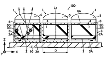
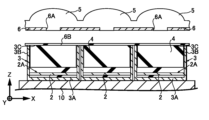
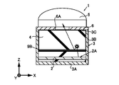
- FIG. 1 is a cross-sectional view of main parts of a light emitting device and an image display device according to a first embodiment of the present disclosure
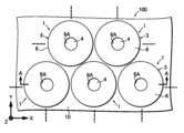
- FIG. FIG. 2 is a plan view of essential parts of the light emitting device and the image display device shown in FIG. 1
- FIG. 3 is a model diagram illustrating the detailed structure of the light emitting device shown in FIGS. 1 and 2
- FIG. 4 is a graph showing the relationship between the aperture diameter of an aperture provided in the light emitting device shown in FIG. 3 and the light intake angle.
- 1 is a cross-sectional view of a main part of a light-emitting device according to a first embodiment, which is an object of luminance measurement;
- FIG. 4 is a cross-sectional view of a main part of a light-emitting device according to a first comparative example, which is an object of luminance measurement
- FIG. 10 is a cross-sectional view of a main part of a light-emitting device according to a second comparative example, which is an object of luminance measurement
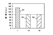
- 7 is a graph showing results of luminance measurement of the light emitting device according to the first embodiment, the light emitting device according to the first comparative example, and the light emitting device according to the second comparative example.
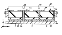
- FIG. 2 is a cross-sectional view of the first process corresponding to FIG. 1, explaining the method of manufacturing the light-emitting device and the image display device according to the first embodiment; It is a 2nd process sectional drawing.
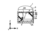
- FIG. 11 is a cross-sectional view of a main part corresponding to FIG. 1 of a light emitting device according to a third embodiment of the present disclosure
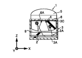
- FIG. 11 is a cross-sectional view of a main part corresponding to FIG. 1 of a light emitting device according to a fourth embodiment of the present disclosure
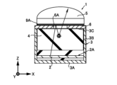
- FIG. 11 is a cross-sectional view of a main part corresponding to FIG. 1 of a light emitting device according to a fifth embodiment of the present disclosure
- FIG. 11 is a cross-sectional view of a main part corresponding to FIG.
- FIG. 20 is a cross-sectional view of a main part corresponding to FIG. 1 of a light emitting device according to a seventh embodiment of the present disclosure
- FIG. 20 is a cross-sectional view of a main part corresponding to FIG. 1 of a light emitting device according to an eighth embodiment of the present disclosure
- FIG. 21 is a plan view of a main part corresponding to FIG. 2 of a light emitting device according to a ninth embodiment of the present disclosure
- FIG. 16B is a plan view of a main part corresponding to FIG. 16A of the light emitting device according to the first modified example of the ninth embodiment
- FIG. 16B is a plan view of a main part corresponding to FIG.
- FIG. 16B is a plan view of a main part corresponding to FIG. 16A of a light emitting device according to a third modified example of the ninth embodiment
- FIG. 20 is a main part cross-sectional view corresponding to FIG. 1 of a light emitting device and an image display device according to a tenth embodiment of the present disclosure
- FIG. 20 is a cross-sectional view of a main part corresponding to FIG. 1 of a light-emitting device and an image display device according to an eleventh embodiment of the present disclosure
- FIG. 20 is a plan view of a main part of a light emitting device and an image display device according to an eleventh embodiment, corresponding to FIG.
- FIG. 20 is a main part cross-sectional view corresponding to FIG. 1 of a light emitting device and an image display device according to a twelfth embodiment of the present disclosure
- FIG. 30 is a schematic cross-sectional view of a main part of a light emitting device according to a thirteenth embodiment of the present disclosure
- First Embodiment A first embodiment describes an example in which the present technology is applied to a light emitting device and an image display device. Here, basic structures and manufacturing methods of the light-emitting device and the image display device will be described. 2.
- Second Embodiment A second embodiment describes a modification of the method for manufacturing the light emitting device and the image display device according to the first embodiment.
- Third Embodiment A third embodiment describes a first modified example of the light reflecting section in the light emitting device and the image display device according to the first embodiment. 4.
- Fourth Embodiment A fourth embodiment will explain a second modification of the light reflecting section in the light emitting device and the image display device according to the first embodiment.
- Fifth Embodiment A fifth embodiment describes a first modification of the light control section in the light emitting device and the image display device according to the first embodiment.
- Sixth Embodiment A sixth embodiment describes a first modification of the light shielding portion in the light emitting device and the image display device according to the first embodiment.
- Seventh Embodiment A seventh embodiment describes a second modification of the light shielding portion in the light emitting device and the image display device according to the first embodiment.
- Eighth Embodiment The eighth embodiment describes a second modification of the light control section in the light emitting device and the image display device according to the first embodiment. 9.
- Ninth Embodiment A ninth embodiment describes a third modification of the light shielding portion in the light emitting device and the image display device according to the first embodiment.
- a plurality of variations of the third modified example will be described.
- Tenth Embodiment A tenth embodiment describes a third modification of the light control section in the light emitting device and the image display device according to the first embodiment.
- Eleventh Embodiment An eleventh embodiment describes a fourth modification of the light shielding portion in the light emitting device and the image display device according to the first embodiment.
- Twelfth Embodiment A twelfth embodiment describes a first modified example of the lens in the light emitting device and the image display device according to the first embodiment.
- Thirteenth Embodiment A thirteenth embodiment describes a second modification of the lens in the light emitting device and the image display device according to the first embodiment.
- a plurality of variations of the second modified example will be described. 14.
- the arrow X direction shown as appropriate indicates one plane direction of the light emitting device 1 and the image display device 100 placed on a plane for convenience.
- the arrow Y direction indicates another planar direction perpendicular to the arrow X direction.
- the arrow Z direction indicates an upward direction orthogonal to the arrow X direction and the arrow Y direction. That is, the arrow X direction, the arrow Y direction, and the arrow Z direction exactly match the X-axis direction, the Y-axis direction, and the Z-axis direction of the three-dimensional coordinate system, respectively. It should be noted that each of these directions is shown to aid understanding of the description and is not intended to limit the direction of the present technology.
- FIG. 2 shows an example of a planar configuration of the light emitting device 1 and the image display device 100.
- the cross-sectional configuration shown in FIG. 1 is a cross-sectional configuration cut along the AA cutting line shown in FIG.
- FIG. 2 some of the components shown in FIG. 1, specifically the lens 5, are omitted.
- the image display device 100 includes a plurality of light emitting devices 1 arranged.
- a plurality of light emitting devices 1 are arranged in each of the arrow X direction and the arrow Y direction.
- the light-emitting devices 1 arranged in the arrow X direction have an arrangement pitch that is half the arrangement pitch of the light-emitting devices 1 with respect to the other light-emitting devices 1 arranged in the arrow X direction adjacent to the arrow Y direction. , are staggered.
- the light emitting device 1 is arranged on the substrate 10 .
- the light emitting device 1 includes a light emitting element 2, a light reflecting portion 3, a light controlling portion 4, a lens 5, and a light shielding portion 6 as main components.
- the substrate 10 is a substrate common to the plurality of light emitting devices 1 arranged, and is also a substrate of the image display device 100 .
- a drive circuit (not shown) for driving the light emitting device 1 is arranged on the substrate 10 .
- the substrate 10 is formed of, for example, a semiconductor substrate such as a silicon substrate, a glass substrate, or a glass epoxy substrate.
- a self-luminous light source is used for the light-emitting element 2 .
- the light emitting element 2 is formed in a circular shape when viewed in the direction of arrow Z (hereinafter simply referred to as “plan view”), and is formed in layers when viewed in the direction of arrow Y (hereinafter simply referred to as “side view”).
- the upper surface of the light emitting element 2 in the direction of the arrow Z (hereinafter simply referred to as "upward direction”) is a light emitting surface 2A.
- light emitting element 2 light is emitted isotropically upward from the light emitting surface 2A.
- the light emission diameter D (see FIGS. 1 and 3) of the light emission surface 2A is the area where light is effectively emitted. is the diameter dimension of
- the light emitting element 2 is formed by, for example, an LED (Light Emitting Diode) here. LEDs are made of III-V compound semiconductors (inorganic compound semiconductors).
- the light emitting element 2 may also be a LASER (Light Amplification by Stimulated Emission of Radiation) made of a compound semiconductor.
- the light emitting element 2 may be an organic EL (Electro-Luminescence) made of an organic semiconductor.
- the light reflecting section 3 includes at least a first light reflecting section 3A and a second light reflecting section 3B.
- the first light reflecting portion 3A is provided on the opposite side of the light emitting element 2 from the light emitting surface 2A, facing the lower surface of the light emitting element 2 and spreading flat. Light emitted from the light emitting surface 2A is reflected upward by the first light reflecting portion 3A.
- the second light reflecting portion 3B surrounds the periphery of the side surface of the light emitting element 2, and extends from the first light reflecting portion 3A beyond the light emitting element 2. As shown in FIG. Light emitted from the light emitting surface 2A is reflected upward by the second light reflecting portion 3B.
- the second light reflecting portion 3B is vertically erected with respect to the first light reflecting portion 3A. Since the second light reflecting portion 3B only needs to have a function of reflecting light upward, for example, the portions facing in the plane direction diverge upward from the first light reflecting portion 3A. It may also be formed by an inclined surface (which is enlarged in diameter).
- the light reflecting section 3 further includes a third light reflecting section 3C.
- the third light reflecting portion 3C is arranged on the light emitting surface 2A side of the light shielding portion 6 arranged to face the light emitting surface 2A of the light emitting element 2 .
- the third light reflecting portion 3C is formed flat. In the third light reflecting portion 3C, the light emitted from the light emitting surface 2A is reflected toward the light emitting surface 2A.
- the first light reflecting portion 3A, the second light reflecting portion 3B, and the third light reflecting portion 3C of the light reflecting portion 3 may be connected to each other, or may be partially or wholly separated. Further, for example, a portion of the second light reflecting portion 3B, specifically, the boundary portion between the light emitting element 2 and the light control portion 4 may be separated.
- Each of the first light reflecting portion 3A, the second light reflecting portion 3B, and the third light reflecting portion 3C is made of a metal having excellent light reflecting properties, such as aluminum (Al). Further, each of the first light reflecting portion 3A, the second light reflecting portion 3B, and the third light reflecting portion 3C may be all formed of a metal body, but the base portion is formed of a resin body, and the resin body A metal body may be formed on the surface. Furthermore, Ag, Au, Pt, Cu, Ti, etc. can also be practically used as a metal body having excellent light reflecting properties.
- the light control unit 4 operates within a region surrounded by the first light reflection unit 3A, the second light reflection unit 3B, and the third light reflection unit 3C of the light reflection unit 3. , are disposed on the light emitting surface 2A side of the light emitting element 2.
- the light control section 4 is made of a light wavelength conversion material that controls (converts) the wavelength of light. That is, the light controller 4 absorbs the light emitted from the light emitting surface 2A and converts the wavelength of the absorbed light.
- the light control unit 4 converts blue light emitted from the light emitting surface 2A into green light, blue light into red light, or blue light into blue light.
- the light emitted from the light emitting surface 2A of the light emitting element 2 is indicated by a "solid line”. Further, the light whose wavelength is controlled by the light control unit 4, that is, the fluorescence excitation light is indicated by "broken line with arrow”. Furthermore, a “star symbol” indicating conversion from light to fluorescence excitation light is shown for convenience at the connection point between the "solid line” and the "broken line with an arrow”. Inorganic phosphors, organic phosphors, or quantum dots, for example, can be used as light wavelength conversion materials.
- the lens 5 is arranged on the opposite side of the light control section 4 from the light emitting element 2 .
- the lens 5 is centered on the optical axis Lc of the light emitted from the light emitting surface 2A.
- the lens 5 is an optical spherical lens projecting upward.
- the lens 5 is made of, for example, a silicon oxide film (SiO 2 ).
- the lens 5 converges the light emitted from the light emitting surface 2 ⁇ /b>A and whose wavelength is controlled through the light control section 4 .
- the lens 5 may be made of an inorganic material such as a silicon nitride film (SiN), an organic material such as a transparent resin, or the like.
- a lens diameter Ld on the plane of the lens 5 having a radius of curvature R is equal to or larger than the light emitting diameter D of the light emitting element 2 (see FIG. 3).
- the lens diameter Ld of the lens 5 is formed to be larger than the light emission diameter D by the thickness of the second light reflecting portion 3B facing the light reflecting portion 3 in the plane direction.
- the light shielding part 6 is arranged between the light control part 4 and the lens 5 and formed in a plate shape.
- the light shielding portion 6 is provided with an opening 6 ⁇ /b>A that passes through the light shielding portion 6 in the thickness direction and allows the wavelength-controlled light from the light control portion 4 to pass therethrough.
- the light shielding portion 6 is formed in the plane direction over the entire upper surface of the light control portion 4 except for the opening 6A, and shields light from the light control portion 4 toward the lens 5 .
- the third light reflecting portion 3C is arranged on the light emitting element 2 side of the light shielding portion 6, so the light directed toward the light shielding portion 6 is reflected toward the light emitting surface 2A side by the third light reflecting portion 3C. be done.
- the light shielding portion 6 includes the third light reflecting portion 3C, it is made of Al.
- the light shielding portion 6 may be formed of a resin body that does not transmit light, for example, a resin body containing black ink.
- the light shielding part 6 may be formed on a base of a metal body having a lower reflectance than Al, for example, and a metal body having a high reflectance may be formed on the surface of this metal body.
- One opening 6A is arranged for one light emitting element 2 .
- the opening 6A is formed in a circular shape in plan view, similar to the shape of the light emitting surface 2A.
- the aperture 6A is formed with an aperture diameter A smaller than the lens diameter Ld and the light emission diameter D (see FIG. 3).
- the aperture diameter A is formed to have the same size over the thickness direction of the light shielding portion 6 . Therefore, the opening end face of the opening 6A is formed in a vertical plane.
- the aperture diameter A is formed to have a dimension equal to or larger than the condensing diameter (spot diameter) Ls of the lens 5 when the lens 5 is irradiated with light from above.
- the aperture diameter A is formed to have a dimension larger than 10 nm.
- the central position of the aperture 6A is aligned with the optical axis Lc.
- the opening 6A allows the light emitted from the light emitting surface 2A and controlled by the light control section 4 to pass therethrough. Furthermore, the opening 6A allows the light emitted from the light emitting surface 2A, reflected by the light reflecting section 3, and controlled by the light control section 4 to pass therethrough.
- the light collection efficiency from the light emitting device 1 to the projection surface 7 can be improved, and a low-profile structure that reduces the height of the light emitting device 1 in the direction of arrow Z can be realized.
- the portion where the light set at the take-in angle ⁇ is condensed on the surface of the light control section 4 through the lens 5 (the portion where the condensed diameter Ls is generated) is defined as the light emission position.
- a height T is defined from the light emitting position to the vertex of the lens 5 .
- FIG. 4 shows the relationship between the capture angle ⁇ and the magnification.
- the horizontal axis is the take-in angle ⁇
- the vertical axis is the magnification.
- Magnification is represented by the following formula.
- Aperture diameter A magnification x emission diameter D
- “R” is the radius of curvature of lens 5 .
- “D” is the light emitting diameter of the light emitting surface 2A.
- the magnification tends to decrease as the radius of curvature R increases.
- the take-in angle ⁇ tends to decrease.
- the opening diameter A of the opening 6A of the light shielding portion 6 decreases, the take-in angle ⁇ tends to decrease.
- FIG. 5A shows a vertical cross-sectional configuration of the light emitting device 1 according to the first embodiment.
- FIG. 5B shows a vertical cross-sectional configuration of a light emitting device 1A according to the first comparative example.
- the light emitting device 1A does not include the light shielding portion 6 (and the third light reflecting portion 3C), the opening 6A and the lens 5 of the light emitting device 1.
- FIG. FIG. 5C shows a vertical cross-sectional configuration of a light emitting device 1B according to a second comparative example.
- the light-emitting device 1B includes the components of the lens 5 of the light-emitting device 1, but does not include the components of the light shielding portion 6 (and the third light reflecting portion 3C) and the opening 6A.
- FIG. 6 shows luminance of each of the light emitting device 1 according to the first embodiment, the light emitting device 1A according to the first comparative example, and the light emitting device 1B according to the second comparative example.
- the vertical axis is luminance.
- Ray tracing is used to measure luminance.
- FIG. 6 shows the measurement results when the take-in angle ⁇ is set to approximately ⁇ 10°.
- Data D5 is the luminance of the light emitting device 1A according to the first comparative example. Here, the luminance of the light emitting device 1A is set to the reference value of "100%”.
- Data D6 is the luminance of the light emitting device 1B according to the second comparative example. Although the lens 5 is provided, the luminance of the light emitting device 1B hardly changes with respect to the luminance of the light emitting device 1A.
- Data D4 is the luminance of the light emitting device 1 according to the first embodiment. The luminance of the light-emitting device 1 is significantly higher than the luminance of the light-emitting device 1A and the luminance of the light-emitting device 1B. The increase in brightness reaches about 50%.
- the light reflecting portion 3 including the first light reflecting portion 3A and the second light reflecting portion 3B is formed (see FIG. 7).
- the light emitting element 2 and the light control section 4 are sequentially formed in the light reflecting section 3 (see FIG. 7).
- a light shielding portion 6 is formed on the light control portion 4, and an opening 6A is formed in the light shielding portion 6 (see FIG. 7).
- a lens forming layer 5A is formed on the light shielding portion 6 including the opening 6A (see FIG. 7).
- the lens forming layer 5A is made of SiO2 , for example.
- the surface portion of the lens forming layer 5A is removed in the region between the light emitting devices 1. Then, as shown in FIG. This removal creates a groove 5B in the surface portion of the lens forming layer 5A.
- a photo-photolithographic technique and an etching technique are used for the removal.
- the lens forming layer 5A is subjected to reflow, and the lens 5 having a spherical shape is formed from the lens forming layer 5A.
- the light-emitting device 1 and the image display device 100 in which a plurality of light-emitting devices 1 are arranged are completed.
- the light emitting device 1 includes a light emitting element 2, a light reflecting section 3, a light controlling section 4, a lens 5, and a light shielding section 6.
- the light emitting element 2 has a light emitting surface 2A.
- the light reflecting portion 3 is arranged on the side opposite to the light emitting surface 2A of the light emitting element 2 and on the side surface side of the light emitting element 2, and reflects the light emitted from the light emitting surface 2A.
- the light control section 4 is arranged on the side of the light emitting surface 2A within the area surrounded by the light reflecting section 3, and controls the wavelength of light.
- the lens 5 is arranged on the opposite side of the light control section 4 from the light emitting element 2, and collects the light emitted from the light emitting surface 2A.
- the light shielding portion 6 is disposed between the light control portion 4 and the lens 5, has an opening 6A passing through in the thickness direction, and shields the light emitted from the light emitting surface 2A. .
- the light emitted from the light-emitting surface 2A of the light-emitting element 2 is emitted from the opening 6A via the light control section 4, reflected by the light reflecting section 3, and passed through the light control section 4 to the opening 6A. emitted from Therefore, as shown in FIG. 6, it is possible to achieve high brightness in the emission direction.
- the light emitting device 1 it is possible to achieve high brightness in the emission direction. can be formed to equivalent dimensions. Therefore, the pitch of the light emitting device 1 can be narrowed. Therefore, in the light-emitting device 1 and the image display device 100 including the light-emitting device 1, it is possible to achieve both high brightness in the emission direction and reduction in pixel pitch.
- the light emitting device 1 can achieve high luminance, low power consumption operation is possible.
- the light emitting device 1 has a light control section 4 as shown in FIG. Therefore, the fluorescence excitation light can also be confined in the light control section 4 to control the wavelength of the light, so that the color mixture of the final emitted light can be reduced.
- the light control section 4 is surrounded by the light reflecting section 3, so that the effective length of the optical path can be lengthened by reflection. Therefore, in the light emitting device 1 and the image display device 100, the height of the light control section 4 can be reduced.
- the aperture diameter A of the aperture 6A is smaller than the lens diameter Ld of the lens 5 and the light emitting diameter D of the light emitting surface 2A. It is larger than the focused light diameter Ls. Therefore, as shown in FIG. 4, the take-in angle .theta. can be reduced.
- the light emitting diameter D of the light emitting surface 2A is the same as or smaller than the lens diameter Ld of the lens 5, as shown in FIGS. Therefore, the arrangement pitch of the light emitting elements 2 can be matched or approximated to the arrangement pitch of the lenses 5, so that the pitch of the light emitting device 1 can be narrowed.
- the light reflecting portion 3 includes a third light reflecting portion 3C that reflects light.
- the third light reflecting portion 3C is arranged on the light shielding portion 6 on the side of the light emitting surface 2A. Therefore, in the light emitting device 1, the light reflected by the third light reflecting portion 3C and emitted from the opening 6A via the light control portion 4 is added, so that it is possible to further increase the brightness in the emitting direction. can.
- the effects obtained by the light-emitting device 1 are obtained as similar effects by the image display device 100 as well.
- Second Embodiment> a light-emitting device 1 and an image display device 100 according to a second embodiment of the present disclosure will be described.
- the same reference numerals are used for the same or substantially the same components as those of the light emitting device 1 and the image display device 100 according to the first embodiment. , and overlapping explanations are omitted.
- the second embodiment describes a modification of the method for manufacturing the light emitting device 1 and the image display device 100 according to the first embodiment.
- FIG. 9 shows cross sections of steps for explaining a method of manufacturing the light emitting device 1 and the image display device 100 according to the second embodiment.
- the light shielding portion 6 and the second light reflecting portion 3B of the light reflecting portion 3 are formed on the previously manufactured light controlling portion 4 and the second light reflecting portion 3B.
- a lens 5 is attached.
- the lens 5 is prefabricated on the light shielding portion 6 by glass molding or resin molding.
- An opening 6 ⁇ /b>A is formed in the light shielding portion 6 .
- Adhesive 6B is used for attachment.
- manufacturing up to the light control unit 4 of the light-emitting device 1 and manufacturing the light shielding unit 6 and the lens 5 are performed under optimum conditions. , can be produced independently. Therefore, manufacturing yield can be improved.
- the lens 5 is formed by imprint lithography technology for transferring the lens shape of the mold to the lens forming layer made of glass, resin, or the like. can be produced.
- the lens 5 is attached after the lens 5 is manufactured.
- FIG. 10 shows the vertical cross-sectional configuration of the light emitting device 1 according to the third embodiment.
- one light-emitting device 1 will be described, and the description of the image display device 100 will be omitted.
- the light emitting device 1 according to the third embodiment includes a third light reflecting portion 3D instead of the third light reflecting portion 3C of the light emitting device 1 according to the first embodiment.
- the third light reflecting portion 3D is arranged on the light shielding portion 6 on the light emitting element 2 side, similarly to the third light reflecting portion 3C.
- the third light reflecting portion 3D is formed as a scattering surface.
- Components other than the above are the same as those of the light emitting device 1 according to the first embodiment.
- the third light reflecting portion 3D can be expected to have the same optical effect as when the light control portion 4 contains a scatterer, the effective optical path length in the light control portion 4 can be increased. Therefore, the height of the light control section 4 can be reduced. Furthermore, color mixture can be reduced. Further, when the light control section 4 contains scatterers, the content of the scatterers in the light control section 4 can be reduced. Therefore, it is possible to reduce variations in the optical characteristics of the light control section 4 and improve optical reliability.
- FIG. 11 shows the vertical cross-sectional configuration of the light emitting device 1 according to the fourth embodiment.
- the light emitting device 1 according to the fourth embodiment includes a third light reflecting portion 3E in the light reflecting portion 3 instead of the third light reflecting portion 3C of the light emitting device 1 according to the first embodiment.
- the third light reflecting portion 3E is arranged on the light shielding portion 6 on the side of the light emitting element 2, like the third light reflecting portion 3C.
- the third light reflecting portion 3E is formed on a curved surface recessed toward the lens 5 side.
- Components other than the above are the same as those of the light emitting device 1 according to the first embodiment.
- the light emitting device 1 according to the fourth embodiment it is possible to obtain the same effects as those obtained by the light emitting device 1 according to the third embodiment. Further, since the light emitting device 1 is provided with the third light reflecting portion 3E, the light not directed to the opening 6A can be reflected by the third light reflecting portion 3E and efficiently focused on the opening 6A. For this reason, it is possible to realize a further increase in luminance in the emission direction.
- FIG. 12 shows the vertical cross-sectional configuration of the light emitting device 1 according to the fifth embodiment.
- the light-emitting device 1 according to the fifth embodiment includes a second lens 8 between the light-emitting surface 2A of the light-emitting element 2 and the light control section 4. As shown in FIG.
- the second lens 8 has a curved surface recessed toward the light emitting surface 2A, and collects light emitted from the light emitting surface 2A.
- the second lens 8 can be formed using the same material as the lens 5, for example.
- Components other than the above are the same as those of the light emitting device 1 according to the first embodiment.
- the light emitting device 1 according to the fifth embodiment it is possible to obtain the same effects as those obtained by the light emitting device 1 according to the third embodiment. Furthermore, since the light emitting device 1 according to the fifth embodiment includes the second lens 8, the light emitted from the light emitting surface 2A can be efficiently condensed toward the opening 6A. For this reason, it is possible to realize a further increase in luminance in the emission direction.
- FIG. 13 shows the vertical cross-sectional configuration of the light emitting device 1 according to the sixth embodiment.
- the light-emitting device 1 according to the sixth embodiment has an opening 6C in the light shielding portion 6 instead of the opening 6A of the light-emitting device 1 according to the first embodiment.
- the aperture 6 ⁇ /b>C is formed on an inclined surface with an aperture diameter A increasing from the light control section 4 toward the lens 5 . That is, the opening end surface of the opening 6C is formed as an inclined surface.
- a fourth light reflecting portion 3F is provided on the inclined surface of the opening 6C.
- the inclined surface of the opening 6C is formed as the fourth light reflecting portion 3F.
- a fourth light reflection portion 3F having a high reflectance is separately formed on the inclined surface of the opening 6C.
- Components other than the above are the same as those of the light emitting device 1 according to the first embodiment.
- the light emitting device 1 according to the sixth embodiment it is possible to obtain the same effects as those obtained by the light emitting device 1 according to the first embodiment. Furthermore, the light-emitting device 1 according to the sixth embodiment has an opening 6C whose diameter is enlarged toward the lens 5 side. A fourth light reflecting portion 3F is arranged in the opening 6C. Therefore, the fourth light reflecting portion 3F of the opening 6C can converge high-angle light to the front in the emission direction. Therefore, it is possible to further improve the brightness of the front surface.
- FIG. 14 shows the vertical cross-sectional configuration of the light emitting device 1 according to the seventh embodiment.
- the light emitting device 1 according to the seventh embodiment has a wavelength cut filter 9A between the light shielding portion 6 and the lens 5 in the light emitting device 1 according to the first embodiment. Note that the wavelength cut filter 9A may be located below the light shielding portion 6.
- the wavelength cut filter 9A is formed as a long-pass edge filter. Although illustration of the detailed configuration is omitted, the wavelength cut filter 9A is, for example, a multilayer film (for example, a multilayer film ( For example, it is formed by (0.5L, 1H, 0.5L) ⁇ 10 layers).
- the wavelength cut filter 9A can reflect only the excitation light whose wavelength is not controlled by the light controller 4 .
- Components other than the above are the same as those of the light emitting device 1 according to the first embodiment.
- the light emitting device 1 according to the seventh embodiment includes the wavelength cut filter 9A, only the excitation light whose wavelength is not controlled by the light control section 4 is reflected, and color mixture can be reduced.
- the effective optical path length in the light control section 4 can be lengthened, the height of the light control section 4 can be reduced.
- FIG. 15 shows the vertical cross-sectional configuration of the light emitting device 1 according to the eighth embodiment.
- the light emitting device 1 according to the eighth embodiment has a wavelength cut filter 9B between the light emitting element 2 and the light controller 4 in the light emitting device 1 according to the first embodiment.
- the wavelength cut filter 9B is formed as a short-pass edge filter.
- the configuration of the wavelength cut filter 9B is the same as the configuration of the wavelength cut filter 9A of the light emitting device 1 according to the seventh embodiment.
- the wavelength cut filter 9B can reflect only fluorescence excitation light in the light control section 4 .
- Components other than the above are the same as those of the light emitting device 1 according to the first embodiment.
- the light emitting device 1 according to the eighth embodiment includes the wavelength cut filter 9B, only the fluorescence excitation light is reflected in the light control section 4, and the optical path length of the light control section 4 can be lengthened. . Therefore, the height of the light control section 4 can be reduced.
- FIG. 16A shows a planar configuration of the light emitting device 1 according to the ninth embodiment.
- the light shielding portion 6 is provided with the opening 6D.
- the opening 6D is formed in an elliptical shape with the arrow X direction as the major axis in plan view. That is, the opening 6D is configured to expand the emission range in the arrow X direction and reduce the emission range in the arrow Y direction.
- the shape of the emitted light on the projection plane 7 (see FIG. 3) is elliptical.
- Components other than the above are the same as those of the light emitting device 1 according to the first embodiment.
- the light emitting device 1 is provided with the elliptical opening 6D, the emission range in the arrow X direction can be expanded and the brightness can be increased.
- the emission range in the arrow Y direction can be reduced to limit the emission range. Therefore, by changing the shape of the opening 6D, it is possible to easily realize a function equivalent to a display system that limits the viewing angle in a certain direction, for example, a peep prevention filter.
- FIG. 16B shows a planar configuration of the light emitting device 1 according to the first modification of the ninth embodiment.
- the light shielding portion 6 is provided with the opening 6E.
- the opening 6E is formed in a square shape in which the lengths of the sides in the arrow X direction and the arrow Y direction are the same in plan view.
- the shape of the emitted light on the projection plane 7 (see FIG. 3) is square.
- a cylindrical lens may be combined as the lens 5 and disposed. preferable.
- Components other than the above are the same as those of the light emitting device 1 according to the first embodiment.
- FIG. 16C shows a planar configuration of a light-emitting device 1 according to a second modification of the ninth embodiment.
- the light shielding portion 6 is provided with the opening 6F.
- the opening 6F is formed in a rectangular shape with long sides in the arrow X direction and short sides in the arrow Y direction in plan view.
- the shape of the emitted light on the projection plane 7 is rectangular.
- Components other than the above are the same as those of the light emitting device 1 according to the first embodiment.
- FIG. 16D shows a planar configuration of the light emitting device 1 according to the third modification of the ninth embodiment.
- the light shielding portion 6 is provided with an opening 6G.
- the opening 6G is formed in a polygonal shape in plan view.
- the opening 6G is formed in a regular hexagonal shape.
- the shape of the emitted light on the projection plane 7 is polygonal.
- the polygonal shape includes a triangular shape, a pentagonal shape, a heptagonal shape, and other polygonal shapes.
- the length of each side may or may not be the same.
- a cylindrical lens can be combined as in the light emitting device 1 according to the first modified example.
- Components other than the above are the same as those of the light emitting device 1 according to the first embodiment.
- FIG. 17 shows a vertical cross-sectional configuration of the light emitting device 1 and the image display device 100 according to the tenth embodiment.
- a light control section 40 is arranged instead of the light control section 4 of the light emitting device 1 according to the first embodiment.
- the light control section 40 is formed of a light scatterer that controls scattering of light.
- the light scatterer is made of a color conversion material. Specifically, red conversion materials, green conversion materials or blue conversion materials are used.
- Components other than the above are the same as those of the light emitting device 1 according to the first embodiment.
- FIG. 18 shows a longitudinal sectional configuration of the light emitting device 1 and the image display device 100 according to the eleventh embodiment.
- FIG. 19 shows a planar configuration of the light emitting device 1 and the image display device 100 shown in FIG.
- the light control section 4 is arranged in one light reflecting section 3 composed of the first light reflecting section 3A and the second light reflecting section 3B, and the light shielding section 6
- a plurality of openings 6A are provided.
- One light emitting element 2 is provided for one opening 6A.
- the number of arrangement is not limited, in the eleventh embodiment, six openings 6A are arranged in one light reflecting section 3, and six light emitting elements 2 are arranged.
- a fine microlens array 50 is arranged on the light shielding portion 6 . In the microlens array 50, lenses are arranged corresponding to the positions where the apertures 6A are arranged.
- Components other than the above are the same as those of the light emitting device 1 according to the first embodiment.
- FIG. 20 shows a vertical cross-sectional configuration of the light emitting device 1 and the image display device 100 according to the twelfth embodiment.
- the opposing lens 51 is arranged above the light shielding portion 6 with the gap 11 interposed therebetween.
- the light exit side of the opposing lens 51 is a flat surface.
- Components other than the above are the same as those of the light emitting device 1 according to the first embodiment.
- the light emitting device 1 according to the twelfth embodiment can obtain the same effects as those obtained by the light emitting device 1 according to the first embodiment. Further, in the light emitting device 1, the light emitting surface side of the opposed lens 51 is configured to be flat. For this reason, it is possible to obtain mechanical merits, for example, a filter or a film can be attached to the opposing lens 51 .
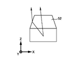
- FIG. 21 shows the vertical cross-sectional configuration of the light-emitting device 1 and the lens 5 of the image display device 100 according to the thirteenth embodiment.
- the lens 5 is formed in a trapezoidal shape or a trapezoidal shape approximated to a spherical shape in a side view.
- Components other than the above are the same as those of the light emitting device 1 according to the first embodiment.
- the light emitting device 1 and the image display device 100 according to the thirteenth embodiment can obtain the same effects as those obtained by the light emitting device 1 and the image display device 100 according to the first embodiment.
- the lens 5 formed in a trapezoidal shape can reduce the shape variation in manufacturing to be smaller than the shape variation of the lens 5 formed in a spherical shape. Therefore, luminance can be made uniform in all the light emitting devices 1 of the image display device 100 .
- the lens 5 can be provided with a Fresnel surface. Also, the lens 5 may be formed by a diffractive lens. When the lens 5 configured in this way is used, the light gathering effect can be improved. Also, the height of the lens 5 can be reduced.
- a light-emitting device includes a light-emitting element, a light reflector, a light controller, a lens, and a light shield.
- the light emitting element has a light emitting surface.
- the light reflecting portion is disposed on the side opposite to the light emitting surface of the light emitting element and on the side surface of the light emitting element, and reflects light emitted from the light emitting surface.
- the light control section is arranged on the light emitting surface side within a region surrounded by the light reflecting section, and controls the wavelength of light.
- the lens is disposed on the opposite side of the light controller from the light emitting element, and collects light emitted from the light emitting surface.
- the light shielding part is disposed between the light control part and the lens, has an opening that penetrates in the thickness direction and allows light to pass through, and shields the light emitted from the light emitting surface.
- the light emitting device light emitted from the light emitting surface of the light emitting element is emitted from the opening via the light control section, reflected by the light reflecting section, and emitted from the opening via the light control section. Therefore, it is possible to achieve high brightness in the emission direction.
- the light emitting diameter of the light emitting surface of the light emitting element and the lens diameter of the lens can be formed to have the same size. Therefore, it is possible to realize a narrower pitch of the light emitting device. Therefore, in the light-emitting device and the image display device including the light-emitting device, it is possible to achieve both high brightness in the emission direction and reduction in pixel pitch.
- the present technology has the following configuration. According to the present technology having the following configuration, it is possible to provide a light-emitting device and an image display device that are capable of achieving both high luminance in the emission direction and reduction in pixel pitch.
- a light-emitting element having a light-emitting surface; a light reflecting part disposed on the side opposite to the light emitting surface of the light emitting element and on the side surface of the light emitting element and reflecting light emitted from the light emitting surface; a lens disposed on the light emitting surface side and condensing light emitted from the light emitting surface; A light-shielding part disposed between the light-emitting surface and the lens, having an opening penetrating in a thickness direction and allowing light to pass therethrough, and shielding the light emitted from the light-emitting surface.
- the aperture diameter of the aperture is smaller than the lens diameter and the light emitting diameter of the light emitting surface and greater than 10 nm;
- the light reflecting part is a first light reflecting portion disposed on the side opposite to the light emitting surface of the light emitting element; A second light reflecting portion disposed on the side surface of the light emitting element,
- the light-emitting device according to 1. (7)
- the opening end surface of the opening is formed on a surface perpendicular to the light emitting surface or on an inclined surface where the opening diameter increases toward the lens.
- a light emitting device according to any one of the above.
- (8) The light emitting device according to (7), wherein a fourth light reflecting portion that reflects light is provided on the opening end face.
- (9) The light emitting device according to any one of (1) to (8), wherein a wavelength cut filter is provided between the light shielding portion and the lens.
- a wavelength cut filter is provided between the light emitting surface and the light control section.
- the light emitting device according to any one of (2) to (10), wherein the light control section is made of a light wavelength conversion material.
- the light control section is formed of a light scatterer.
- the light-emitting device according to claim 1.
- the light emitting device according to any one of (1) to (13), wherein the center of the opening is aligned with the optical axis of the light emitted from the light emitting surface.
- the light emitting device according to any one of (1) to (14), wherein a plurality of the openings are provided in the light shielding portion.
- the light-emitting element is made of an inorganic compound semiconductor or an organic semiconductor.
- the light emitting device a light-emitting element having a light-emitting surface; a light reflecting part disposed on the side opposite to the light emitting surface of the light emitting element and on the side surface of the light emitting element and reflecting light emitted from the light emitting surface; a lens disposed on the light emitting surface side and condensing light emitted from the light emitting surface; a light shielding part disposed between the light emitting surface and the lens, having an opening penetrating in a thickness direction and allowing light to pass therethrough, and shielding the light emitted from the light emitting surface.
- Device (20) The image display device according to (19), wherein in each of the plurality of light emitting devices, the arrangement pitch of the light emitting elements is the same as the arrangement pitch of the lenses.
Landscapes
- Physics & Mathematics (AREA)
- General Physics & Mathematics (AREA)
- Engineering & Computer Science (AREA)
- Theoretical Computer Science (AREA)
- Led Device Packages (AREA)
Priority Applications (3)
| Application Number | Priority Date | Filing Date | Title |
|---|---|---|---|
| CN202280051675.1A CN117813697A (zh) | 2021-07-30 | 2022-03-03 | 发光装置和图像显示装置 |
| JP2023538239A JP7845368B2 (ja) | 2021-07-30 | 2022-03-03 | 発光装置及び画像表示装置 |
| US18/578,126 US20240332470A1 (en) | 2021-07-30 | 2022-03-03 | Light-emitting device and image display device |
Applications Claiming Priority (2)
| Application Number | Priority Date | Filing Date | Title |
|---|---|---|---|
| JP2021-125300 | 2021-07-30 | ||
| JP2021125300 | 2021-07-30 |
Publications (1)
| Publication Number | Publication Date |
|---|---|
| WO2023007804A1 true WO2023007804A1 (ja) | 2023-02-02 |
Family
ID=85087748
Family Applications (1)
| Application Number | Title | Priority Date | Filing Date |
|---|---|---|---|
| PCT/JP2022/009155 Ceased WO2023007804A1 (ja) | 2021-07-30 | 2022-03-03 | 発光装置及び画像表示装置 |
Country Status (4)
| Country | Link |
|---|---|
| US (1) | US20240332470A1 (https=) |
| JP (1) | JP7845368B2 (https=) |
| CN (1) | CN117813697A (https=) |
| WO (1) | WO2023007804A1 (https=) |
Cited By (2)
| Publication number | Priority date | Publication date | Assignee | Title |
|---|---|---|---|---|
| WO2025117838A1 (en) * | 2023-11-30 | 2025-06-05 | Lumileds Llc | Microled with trapezoidal micro-structures |
| WO2025205907A1 (ja) * | 2024-03-27 | 2025-10-02 | ソニーグループ株式会社 | 発光装置および画像表示装置 |
Citations (6)
| Publication number | Priority date | Publication date | Assignee | Title |
|---|---|---|---|---|
| JP2016115729A (ja) * | 2014-12-11 | 2016-06-23 | 日亜化学工業株式会社 | 発光装置の製造法 |
| US20170062674A1 (en) * | 2015-08-31 | 2017-03-02 | Samsung Display Co., Ltd. | Display apparatus and manufacturing method thereof |
| JP2019514217A (ja) * | 2016-04-12 | 2019-05-30 | クリー インコーポレイテッドCree Inc. | 高密度にピクセル化したマルチledチップ、これを組み込んだデバイス、およびこれを製造する方法 |
| JP2020057756A (ja) * | 2018-09-26 | 2020-04-09 | 日亜化学工業株式会社 | 発光装置およびその製造方法 |
| US20200144228A1 (en) * | 2017-06-22 | 2020-05-07 | Osram Oled Gmbh | Optoelectronic component |
| JP2020205417A (ja) * | 2019-06-12 | 2020-12-24 | 東レ株式会社 | マイクロledディスプレイ装置 |
Family Cites Families (2)
| Publication number | Priority date | Publication date | Assignee | Title |
|---|---|---|---|---|
| TW200614548A (en) * | 2004-07-09 | 2006-05-01 | Matsushita Electric Industrial Co Ltd | Light-emitting device |
| US9178123B2 (en) * | 2012-12-10 | 2015-11-03 | LuxVue Technology Corporation | Light emitting device reflective bank structure |
-
2022
- 2022-03-03 WO PCT/JP2022/009155 patent/WO2023007804A1/ja not_active Ceased
- 2022-03-03 US US18/578,126 patent/US20240332470A1/en active Pending
- 2022-03-03 JP JP2023538239A patent/JP7845368B2/ja active Active
- 2022-03-03 CN CN202280051675.1A patent/CN117813697A/zh active Pending
Patent Citations (6)
| Publication number | Priority date | Publication date | Assignee | Title |
|---|---|---|---|---|
| JP2016115729A (ja) * | 2014-12-11 | 2016-06-23 | 日亜化学工業株式会社 | 発光装置の製造法 |
| US20170062674A1 (en) * | 2015-08-31 | 2017-03-02 | Samsung Display Co., Ltd. | Display apparatus and manufacturing method thereof |
| JP2019514217A (ja) * | 2016-04-12 | 2019-05-30 | クリー インコーポレイテッドCree Inc. | 高密度にピクセル化したマルチledチップ、これを組み込んだデバイス、およびこれを製造する方法 |
| US20200144228A1 (en) * | 2017-06-22 | 2020-05-07 | Osram Oled Gmbh | Optoelectronic component |
| JP2020057756A (ja) * | 2018-09-26 | 2020-04-09 | 日亜化学工業株式会社 | 発光装置およびその製造方法 |
| JP2020205417A (ja) * | 2019-06-12 | 2020-12-24 | 東レ株式会社 | マイクロledディスプレイ装置 |
Cited By (2)
| Publication number | Priority date | Publication date | Assignee | Title |
|---|---|---|---|---|
| WO2025117838A1 (en) * | 2023-11-30 | 2025-06-05 | Lumileds Llc | Microled with trapezoidal micro-structures |
| WO2025205907A1 (ja) * | 2024-03-27 | 2025-10-02 | ソニーグループ株式会社 | 発光装置および画像表示装置 |
Also Published As
| Publication number | Publication date |
|---|---|
| CN117813697A (zh) | 2024-04-02 |
| US20240332470A1 (en) | 2024-10-03 |
| JP7845368B2 (ja) | 2026-04-14 |
| JPWO2023007804A1 (https=) | 2023-02-02 |
Similar Documents
| Publication | Publication Date | Title |
|---|---|---|
| US11728370B2 (en) | Image display device | |
| CN115336015B (zh) | 显示基板以及显示装置 | |
| JP6265796B2 (ja) | 発光モジュール | |
| US10304813B2 (en) | Display device having a plurality of bank structures | |
| US8669571B2 (en) | Light distribution controller, light-emitting device using the same, and method for fabricating light distribution controller | |
| CN114665047B (zh) | 显示器件及其制备方法 | |
| JP7775299B2 (ja) | 高効率発光素子、それを有するユニットピクセル、およびそれを有するディスプレイ装置 | |
| JP2017139464A (ja) | 発光素子及びその製造方法 | |
| US11776990B2 (en) | Micro light-emitting diode display panel | |
| WO2023007804A1 (ja) | 発光装置及び画像表示装置 | |
| WO2021166772A1 (ja) | 発光デバイス、および発光デバイスの製造方法 | |
| CN113809064A (zh) | 显示面板、显示装置和光场显示装置 | |
| WO2022014421A1 (ja) | 発光装置および画像表示装置 | |
| CN112037674B (zh) | 面光源及其制备方法和显示装置 | |
| CN1933261A (zh) | 半导体激光单元及制造光反射膜的方法 | |
| TWI836956B (zh) | 顯示裝置 | |
| KR102801752B1 (ko) | 전자 디스플레이를 위한 픽셀 구조 및 이러한 디스플레이를 포함하는 전자 장치 | |
| WO2024024272A1 (ja) | 発光装置 | |
| CN117242395A (zh) | 显示面板和显示装置 | |
| WO2017104547A1 (ja) | 発光ユニットおよび表示装置 | |
| US20240379904A1 (en) | Light emitting module and apparatus having light emitting element | |
| CN119789656A (zh) | 微发光器件显示面板 | |
| TW202531954A (zh) | 半導體晶片 | |
| CN120636270A (zh) | 显示装置 | |
| WO2023189384A1 (ja) | 発光デバイスおよび画像表示装置 |
Legal Events
| Date | Code | Title | Description |
|---|---|---|---|
| 121 | Ep: the epo has been informed by wipo that ep was designated in this application |
Ref document number: 22848888 Country of ref document: EP Kind code of ref document: A1 |
|
| WWE | Wipo information: entry into national phase |
Ref document number: 18578126 Country of ref document: US |
|
| WWE | Wipo information: entry into national phase |
Ref document number: 2023538239 Country of ref document: JP |
|
| WWE | Wipo information: entry into national phase |
Ref document number: 202280051675.1 Country of ref document: CN |
|
| NENP | Non-entry into the national phase |
Ref country code: DE |
|
| 122 | Ep: pct application non-entry in european phase |
Ref document number: 22848888 Country of ref document: EP Kind code of ref document: A1 |