WO2023007789A1 - 慣性計測装置、および慣性計測装置の作動方法、撮像装置、表示装置、並びにプログラム - Google Patents
慣性計測装置、および慣性計測装置の作動方法、撮像装置、表示装置、並びにプログラム Download PDFInfo
- Publication number
- WO2023007789A1 WO2023007789A1 PCT/JP2022/007795 JP2022007795W WO2023007789A1 WO 2023007789 A1 WO2023007789 A1 WO 2023007789A1 JP 2022007795 W JP2022007795 W JP 2022007795W WO 2023007789 A1 WO2023007789 A1 WO 2023007789A1
- Authority
- WO
- WIPO (PCT)
- Prior art keywords
- unit
- orientation
- future
- acceleration
- angular velocity
- Prior art date
- Legal status (The legal status is an assumption and is not a legal conclusion. Google has not performed a legal analysis and makes no representation as to the accuracy of the status listed.)
- Ceased
Links
Images


Classifications
-
- G—PHYSICS
- G01—MEASURING; TESTING
- G01C—MEASURING DISTANCES, LEVELS OR BEARINGS; SURVEYING; NAVIGATION; GYROSCOPIC INSTRUMENTS; PHOTOGRAMMETRY OR VIDEOGRAMMETRY
- G01C21/00—Navigation; Navigational instruments not provided for in groups G01C1/00 - G01C19/00
- G01C21/10—Navigation; Navigational instruments not provided for in groups G01C1/00 - G01C19/00 by using measurements of speed or acceleration
- G01C21/12—Navigation; Navigational instruments not provided for in groups G01C1/00 - G01C19/00 by using measurements of speed or acceleration executed aboard the object being navigated; Dead reckoning
- G01C21/16—Navigation; Navigational instruments not provided for in groups G01C1/00 - G01C19/00 by using measurements of speed or acceleration executed aboard the object being navigated; Dead reckoning by integrating acceleration or speed, i.e. inertial navigation
- G01C21/165—Navigation; Navigational instruments not provided for in groups G01C1/00 - G01C19/00 by using measurements of speed or acceleration executed aboard the object being navigated; Dead reckoning by integrating acceleration or speed, i.e. inertial navigation combined with non-inertial navigation instruments
- G01C21/1656—Navigation; Navigational instruments not provided for in groups G01C1/00 - G01C19/00 by using measurements of speed or acceleration executed aboard the object being navigated; Dead reckoning by integrating acceleration or speed, i.e. inertial navigation combined with non-inertial navigation instruments with passive imaging devices, e.g. cameras
-
- G—PHYSICS
- G02—OPTICS
- G02B—OPTICAL ELEMENTS, SYSTEMS OR APPARATUS
- G02B27/00—Optical systems or apparatus not provided for by any of the groups G02B1/00 - G02B26/00, G02B30/00
- G02B27/64—Imaging systems using optical elements for stabilisation of the lateral and angular position of the image
- G02B27/646—Imaging systems using optical elements for stabilisation of the lateral and angular position of the image compensating for small deviations, e.g. due to vibration or shake
-
- G—PHYSICS
- G03—PHOTOGRAPHY; CINEMATOGRAPHY; ANALOGOUS TECHNIQUES USING WAVES OTHER THAN OPTICAL WAVES; ELECTROGRAPHY; HOLOGRAPHY
- G03B—APPARATUS OR ARRANGEMENTS FOR TAKING PHOTOGRAPHS OR FOR PROJECTING OR VIEWING THEM; APPARATUS OR ARRANGEMENTS EMPLOYING ANALOGOUS TECHNIQUES USING WAVES OTHER THAN OPTICAL WAVES; ACCESSORIES THEREFOR
- G03B5/00—Adjustment of optical system relative to image or object surface other than for focusing
-
- H—ELECTRICITY
- H04—ELECTRIC COMMUNICATION TECHNIQUE
- H04N—PICTORIAL COMMUNICATION, e.g. TELEVISION
- H04N23/00—Cameras or camera modules comprising electronic image sensors; Control thereof
- H04N23/60—Control of cameras or camera modules
- H04N23/68—Control of cameras or camera modules for stable pick-up of the scene, e.g. compensating for camera body vibrations
- H04N23/681—Motion detection
- H04N23/6812—Motion detection based on additional sensors, e.g. acceleration sensors
-
- H—ELECTRICITY
- H04—ELECTRIC COMMUNICATION TECHNIQUE
- H04N—PICTORIAL COMMUNICATION, e.g. TELEVISION
- H04N23/00—Cameras or camera modules comprising electronic image sensors; Control thereof
- H04N23/60—Control of cameras or camera modules
- H04N23/68—Control of cameras or camera modules for stable pick-up of the scene, e.g. compensating for camera body vibrations
- H04N23/682—Vibration or motion blur correction
- H04N23/685—Vibration or motion blur correction performed by mechanical compensation
- H04N23/687—Vibration or motion blur correction performed by mechanical compensation by shifting the lens or sensor position
-
- G—PHYSICS
- G03—PHOTOGRAPHY; CINEMATOGRAPHY; ANALOGOUS TECHNIQUES USING WAVES OTHER THAN OPTICAL WAVES; ELECTROGRAPHY; HOLOGRAPHY
- G03B—APPARATUS OR ARRANGEMENTS FOR TAKING PHOTOGRAPHS OR FOR PROJECTING OR VIEWING THEM; APPARATUS OR ARRANGEMENTS EMPLOYING ANALOGOUS TECHNIQUES USING WAVES OTHER THAN OPTICAL WAVES; ACCESSORIES THEREFOR
- G03B2205/00—Adjustment of optical system relative to image or object surface other than for focusing
- G03B2205/0007—Movement of one or more optical elements for control of motion blur
-
- G—PHYSICS
- G06—COMPUTING OR CALCULATING; COUNTING
- G06N—COMPUTING ARRANGEMENTS BASED ON SPECIFIC COMPUTATIONAL MODELS
- G06N3/00—Computing arrangements based on biological models
- G06N3/02—Neural networks
- G06N3/08—Learning methods
- G06N3/09—Supervised learning
Definitions
- the present disclosure relates to an inertial measurement device, an operation method of the inertial measurement device, an imaging device, a display device, and a program, and in particular, an inertial measurement device capable of improving the detection accuracy of a multi-IMU and correcting image shake with high precision.
- the present invention relates to a measurement device, an operation method of an inertial measurement device, an imaging device, a display device, and a program.
- a multi-IMU has been proposed that improves detection accuracy by integrating the detection results of multiple IMUs (Inertial Measurement Units).
- Patent Documents 2 and 3 a technique has been proposed in which an IMU is installed in an imaging device, and based on observed values, the motion of the image sensor is controlled by an actuator or the like to correct image blur.
- the movement of the image sensor is controlled by the actuator or the like based on the observation value of the IMU. Since a time lag occurs until the timing of the correction, there is a risk that appropriate shake correction cannot be achieved.
- the present disclosure has been made in view of such circumstances, and in particular, in correcting shake, it is possible to realize appropriate shake correction that takes into account the time lag from the timing of observation of the IMU until the movement of the actuator or the like is controlled. It is.
- An inertial measurement device and a program include an IMU (Inertial Measurement Unit) that detects current angular velocity and acceleration, and based on the current angular velocity and acceleration detected by the IMU, for a predetermined time and a predictor for predicting future angular velocities and accelerations, and a program.
- IMU Inertial Measurement Unit
- a method of operating an inertial measurement device is a method of operating an inertial measurement device including an IMU (Inertial Measurement Unit) that detects current angular velocity and acceleration, wherein the current detected by the IMU is predicting future angular velocities and accelerations for a predetermined time based on the angular velocities and accelerations of the inertial measurement unit.
- IMU Inertial Measurement Unit
- the current angular velocity and acceleration are detected, and based on the current angular velocity and acceleration, future angular velocity and acceleration are predicted for a predetermined period of time.
- An imaging device includes an image sensor that captures an image, a driving unit that drives the image sensor, an inertial measurement unit that detects future angular velocity and acceleration of the image sensor for a predetermined period of time, a future position/orientation detector that detects a future position and orientation of the image sensor based on the future angular velocity and acceleration; and a shake of the image sensor that is corrected based on the future position and orientation of the image sensor.
- the inertial measurement unit includes an IMU (Inertial Measurement Unit) that detects the current angular velocity and acceleration of the main body, and the IMU and a prediction unit that predicts future angular velocity and acceleration for a predetermined period of time based on the current angular velocity and acceleration.
- IMU Inertial Measurement Unit
- an image sensor that captures an image is driven, a future angular velocity and acceleration of the image sensor are detected for a predetermined time, and based on the future angular velocity and acceleration, the image sensor A future position and orientation are detected, the image sensor is controlled to correct shake based on the future position and orientation of the image sensor, and the current angular velocity and acceleration of the main body are detected and detected. Based on the present angular velocity and acceleration, future angular velocity and acceleration are predicted for a predetermined period of time.
- a display device includes a display unit that displays an image that can be viewed by a user while being worn in front of the user's head, and a display unit that displays a future angular velocity and acceleration of the head for a predetermined time.
- an inertial measurement unit for detecting; a future position/orientation detection unit for detecting a future position and orientation of the head based on the future angular velocity and acceleration; and a future position and orientation of the head based on the a shake correction unit that corrects shake of the image displayed on the display unit
- the inertial measurement unit includes an IMU (Inertial Measurement Unit) that detects current angular velocity and acceleration; a prediction unit for predicting a future angular velocity and acceleration for a predetermined period of time based on the angular velocity and acceleration of the display device.
- IMU Inertial Measurement Unit
- an image that can be viewed by the user is displayed while being worn in front of the user's head, the future angular velocity and acceleration of the head are detected for a predetermined time, and the future angular velocity and acceleration are detected for a predetermined period of time.
- a future position and orientation of the head is detected based on the angular velocity and acceleration of the head, and a shake of the image displayed on the display unit is corrected based on the future position and orientation of the head. are detected, and future angular velocities and accelerations are predicted for a predetermined period of time based on the detected current angular velocities and accelerations.
- FIG. 5 is a diagram for explaining an external configuration example of the multi-IMU in FIG. 4;
- FIG. 5 is a diagram for explaining an external configuration example of the multi-IMU in FIG. 4;
- 5 is a diagram for explaining functions realized by the multi-IMU in FIG. 4;
- FIG. 5 is a diagram illustrating a configuration example of a sensor position detection unit in FIG.
- FIG. 4 is a flowchart for explaining angular velocity and acceleration detection processing by the multi-IMU of FIG. 4; 5 is a flowchart for explaining imaging processing by the imaging device of FIG. 4; 5 is a flowchart for explaining learning processing by the imaging device of FIG. 4; It is a figure explaining the example of composition of the imaging device concerning a 2nd embodiment of this indication.
- 13 is a diagram for explaining functions realized by the multi-IMU of FIG. 12;
- FIG. 13 is a flowchart for explaining angular velocity and acceleration detection processing by the multi-IMU of FIG. 12; 13 is a flowchart for explaining learning processing by the imaging device of FIG. 12;
- FIG. 12 is a diagram for explaining functions realized by the multi-IMU of FIG. 12;
- FIG. 13 is a flowchart for explaining angular velocity and acceleration detection processing by the multi-IMU of FIG. 12; 13 is a flowchart for explaining learning processing by the imaging device of FIG. 12;
- FIG. 12 is a flowchar
- 11 is a diagram illustrating a configuration example of a VR glasses device according to a third embodiment of the present disclosure
- 17 is a flowchart for explaining display processing by the VR glasses device of FIG. 16
- It is a figure explaining the structural example of a general-purpose personal computer.
- camera shake refers to shake of an image caused by shake of the body of the imaging device that occurs when the user grips and operates the imaging device by hand. shall be For this reason, for example, for an imaging device mounted on a mobile device such as a drone or a vehicle that is driven by a motor or an engine, shake in imaging caused by high-frequency vibration generated by the driving of the motor or engine can also cause camera shake. shall be included in Further, the term "shake" of an image is also assumed to include camera shake.
- Fig. 1 shows an imaging system that detects the orientation and position of the main body of the imaging device using an IMU, and drives the image sensor based on the information on the detected orientation and position of the main body of the imaging device, thereby realizing image stabilization. It is a configuration example of an apparatus.
- the imaging device 11 in FIG. 1 includes an IMU (Inertial Measurement Unit) 31, a position and orientation detection unit 32, a drive control unit 33, drive units 34a-1, 34a-2, and 34b-1, 34b-2, Also, an image sensor 35 is provided.
- IMU Inertial Measurement Unit
- position and orientation detection unit 32 a position and orientation detection unit
- drive control unit 33 drive units 34a-1, 34a-2, and 34b-1, 34b-2
- an image sensor 35 is provided.
- the IMU 31 includes, for example, an acceleration sensor that detects acceleration, which is translational motion, in each of the three axial directions consisting of the XYZ axes, and a gyro sensor that detects angular velocity, which is rotational motion.
- the respective accelerations and angular velocities are detected and output to the position/orientation detection unit 32 .
- the position/orientation detection unit 32 detects the orientation of the main body of the imaging device 11 based on the angular velocity detected by the IMU 31, detects the position of the main body of the imaging device 11 based on the acceleration detected by the IMU 31, Output to the drive control unit 33 .
- the drive control unit 33 drives a control signal for driving the image sensor 35 in a direction that cancels out the shake (movement) that has occurred, based on information on the position and orientation of the main body of the imaging device 11 detected by the position/orientation detection unit 32 . Output to each of the sections 34a-1, 34a-2 and 34b-1, 34b-2.
- the drive units 34a-1 and 34a-2 are drive mechanisms such as actuators that physically drive the image sensor 35. Based on control signals supplied from the drive control unit 33, the image sensor 35 is moved horizontally in the drawing. direction.
- the drive units 34b-1 and 34b-2 are drive mechanisms such as actuators that physically drive the image sensor 35. Based on control signals supplied from the drive control unit 33, the image sensor 35 is moved vertically in the drawing. direction.
- the drive units 34a-1, 34a-2 and 34b-1, 34b-2 are also simply referred to as the drive unit 34 when there is no need to distinguish between them.
- the image sensor 35 is composed of a CMOS (Complementary Metal Oxide Semiconductor), a CCD (Charge Coupled Device), or the like, and captures an image by generating pixel signals according to the amount of incident light, and outputs the captured image. .
- CMOS Complementary Metal Oxide Semiconductor
- CCD Charge Coupled Device
- the drive control unit 33 controls the position and orientation of the image sensor 35 by driving the drive unit 34 by inertial navigation using the IMU 31 and the position/orientation detection unit 32 .
- the drive control unit 33 controls the drive unit 34 so as to cancel the shake (movement) of the image sensor 35 by feedforward control based on the detection result of the position/orientation detection unit 32 .
- the drive unit 34 drives the image sensor 35 with the direction and amount of movement based on the control signal supplied from the drive control unit 33 .
- the image sensor 35 is driven in a direction in which camera shake is canceled in accordance with changes in the position and orientation of the imaging device 11, thereby realizing camera shake correction.
- the IMU 31 is provided outside the range driven by the drive unit 34 that drives the image sensor 35, so the position and posture of the main body of the imaging device 11 are appropriately adjusted. However, the position and orientation of the image sensor 35 cannot be properly detected.
- the movement of the image sensor 35 is transmitted by the drive unit 34 which is a physical drive mechanism attached to the main body of the image pickup device 11, the movement of the main body of the image pickup device 11 itself can be followed. becomes movement.
- the motion of the image sensor 35 follows the motion of the main body of the imaging device 11 and is delayed by a predetermined time from the motion of the imaging device 11. There was a fear that the correction could not be realized.
- the motion of the image sensor in the future is predicted for a predetermined period of time from the current motion of the imaging device by learning, and the image sensor is driven to cancel out the shake (movement) based on the prediction result.
- the image sensor is driven to cancel out the shake (movement) based on the prediction result.
- FIG. 2 shows a configuration example for explaining an overview of an imaging apparatus that predicts the future position and orientation of an image sensor for a predetermined time by learning and controls the position and orientation of the image sensor based on the prediction results.
- the imaging device 51 in FIG. a current position/posture detection unit 67 , a current position/posture estimation unit 68 , and a prediction error calculation unit 69 .
- the multi-IMU 61 is composed of a plurality of IMUs, integrates the current angular velocity and acceleration of the main body of the imaging device 51 detected by the plurality of IMUs, and outputs it to the current position/orientation estimation unit 68 as a current output.
- the multi-IMU 61 integrates the current angular velocity and acceleration of the main body of the imaging device 51 detected by a plurality of IMUs, and predicts the future angular velocity and acceleration for a predetermined time based on the integrated current angular velocity and acceleration. , is output to the future position/posture detection unit 62 as a predicted output.
- the multi-IMU 61 acquires the control amount target value that the drive control unit 63 supplies to the drive unit 64 as prediction error feedback, and uses the current angular velocity and acceleration of the main body of the imaging device 51 and the prediction error feedback to obtain the current Based on the angular velocity and acceleration of the main body of the imaging device 51, learning is performed for predicting the future angular velocity and acceleration of the image sensor 65 for a predetermined period of time.
- the multi-IMU 61 predicts the future angular velocity and acceleration of the image sensor 65 for a predetermined time based on the current angular velocity and acceleration of the main body of the imaging device 51 .
- the future position/orientation detection unit 62 detects the position and orientation of the image sensor 65 at the future timing for a predetermined time based on the angular velocity and acceleration of the image sensor 65 for a predetermined time future supplied from the multi-IMU 61, and performs drive control. Output to unit 63 .
- the drive control unit 63 acquires information on the position and orientation of the image sensor 65 at a predetermined time in the future supplied from the future position/orientation detection unit 62 .
- the drive control unit 63 also calculates the current position and orientation of the image sensor 65 estimated by the current position/orientation estimation unit 68 from the current angular velocity and acceleration of the main body supplied from the prediction error calculation unit 69, and the sensor position and orientation. From the current angular velocity and acceleration of the actual image sensor 65 obtained by the detection unit 66, information of the prediction error, which is the difference between the actual current position and orientation of the image sensor 65 obtained by the current position/orientation detection unit 67, is obtained. do.
- the drive control unit 63 considers the position and orientation prediction errors for the information on the position and orientation of the image sensor 65 at the timing a predetermined time in the future, which is supplied from the future position and orientation detection unit 62 . , set control amount target values for the position and attitude of the image sensor 65, and supply them as control signals to the drive units 64a-1, 64a-2, 64b-1, and 64b-2.
- the drive control unit 63 supplies the control amount target value to the multi-IMU 61 as prediction error feedback.
- the driving units 64a-1, 64a-2, 64b-1, 64b-2 are configured corresponding to the driving units 34a-1, 34a-2, 34b-1, 34b-2 in FIG.
- the image sensor 65 is driven in the direction to absorb the shake based on the control amount target value, which is the control signal supplied from the controller.
- the drive units 64a-1, 64a-2, 4b-1, and 64b-2 absorb the generated shake so that the image sensor 65 can maintain the position and orientation that are the control amount target values that are the control signals. Drive the position and orientation of the image sensor 65 in the direction.
- the image sensor 65 has a configuration corresponding to the image sensor 35 of FIG. captures an image and outputs the captured image.
- the sensor position detection unit 66 is integrated with the image sensor 65 , detects the movement amount of the image sensor 65 in the three-dimensional direction, and outputs it to the current position/orientation detection unit 67 .
- the current position and orientation detection unit 67 detects the current position and orientation of the image sensor 65 based on the amount of movement of the image sensor 65 supplied from the sensor position detection unit 66 and outputs them to the prediction error calculation unit 69 .
- the current position/orientation estimation unit 68 estimates the position and orientation of the image sensor 65 based on information on the angular velocity and acceleration of the body of the imaging device 51 supplied from the multi-IMU 61 , and outputs the estimation result to the prediction error calculation unit 69 . do.
- the prediction error calculation unit 69 estimates the position and orientation of the image sensor 65 based on the position and orientation of the main body of the imaging device 51 supplied from the current position and orientation estimation unit 68, and the current position and orientation detection unit 67 detects the position and orientation. The difference from the detection result of the actual position and orientation of the image sensor 65 is calculated and supplied to the drive control unit 63 as a prediction error.
- the drive control unit 63 calculates the difference between the current position and orientation of the image sensor estimated by the current position and orientation estimation unit 68 and the actual current position and orientation of the image sensor 65 detected by the current position and orientation detection unit 67. is obtained as the prediction error.
- the drive control unit 63 calculates the amount of control of the image sensor 65 based on the position and orientation of the image sensor 65 at a predetermined time future timing supplied from the future position/orientation detection unit 62 .
- a target position and orientation are set, a control signal for driving the drive unit 64 is generated, and the control signal is supplied to the drive unit 64 to drive it.
- the drive control unit 63 calculates the position and orientation of the image sensor 65 for a predetermined time in the future, taking into account prediction errors and delays related to the operation of the drive unit 64, and determines the position of the image sensor that will be the control amount target value. and posture can be set.
- the drive control unit 63 can set the position and orientation of the image sensor 65 necessary for taking the position and orientation predicted at future timing for a predetermined time as the control amount target value. , it becomes possible to output the control signal based on the control amount target value to the drive unit 64 in consideration of the delay.
- the drive control unit 63 supplies the control amount target value to the multi-IMU 61 as prediction error feedback.
- the multi-IMU 61 generates its own current angular velocity and acceleration based on the current angular velocity and acceleration of the main body of the imaging device 51 and the prediction error feedback consisting of the control amount target value in the drive control unit 63. Also, coefficients are generated by predictive learning to predict the angular velocity and acceleration of the image sensor 65 at future timing for a predetermined time.
- the multi-IMU 61 predicts the angular velocity and acceleration of the image sensor 65 at future timing for a predetermined time from the current angular velocity and acceleration of the main body of the imaging device 51 using coefficients generated based on prediction learning. , to the future position/orientation detector 62 .
- the multi-IMU 61 consists of multiple IMUs consisting of a 3-axis gyro sensor that detects rotational motion as angular velocity AV and a 3-axis acceleration sensor that detects translational motion as acceleration A, and integrates the detection results of multiple IMUs. and output.
- the multi-IMU 61 outputs, as a current output, the angular velocity AV and the acceleration A in the main body of the imaging device 51, which are the integrated result of multiple IMUs.
- a current position/orientation calculation RC is performed based on the current output consisting of the angular velocity AV and the acceleration A in the main body of the imaging device 51, so that the position P and the orientation AT based on the current output in the main body of the imaging device 51 are calculated. calculated.
- the angular velocity AV is integrated to obtain the attitude AT based on the current output in the main body of the imaging device 51 .
- the acceleration A supplied from the multi-IMU 61 is the acceleration in the local coordinate system, in the current position/orientation calculation RC, it is converted to the global coordinate system by the orientation AT, and is further integrated to obtain the image pickup device 51 A velocity V in the global coordinate system based on the current output at the main body of is obtained.
- the position P of the global coordinate system based on the current output in the main body of the imaging device 51 is obtained.
- the position P and orientation AT obtained by the current position and orientation calculation RC are obtained as the position and orientation RCATP of the main body of the imaging device 51 based on the current output of the multi-IMU 61 . Then, the position and orientation RCATP of the main body of the imaging device 51 based on the current output of the multi-IMU 61 are used as estimated values of the position and orientation of the image sensor 65 at the current time.
- a sensor position detection unit 66 integrated with the image sensor 65 detects the position and orientation RCATP of the image sensor 65 .
- the position and orientation RCATP of the image sensor 65 based on the current output of the multi-IMU 61 are estimated values based on the position and orientation of the body of the imaging device 51, and are strictly different from the actual position and orientation RSATP of the image sensor 65. do not match.
- the difference between the position and orientation RCATP of the image sensor 65 based on the current output of the multi-IMU 61 and the position and orientation RSATP of the image sensor 65 is calculated as the error D.
- This error D has a value corresponding to the positional relationship between the multi-IMU 61 and the sensor position detection section 66 and the delay that occurs when the driving section 64 actually drives the image sensor 65 .
- the future prediction FP is made based on the angular velocity AV and the acceleration A, which are the current outputs of the body of the imaging device 51, and the angular velocity and acceleration of the body of the imaging device 51 in the future for a predetermined time are obtained. .
- the future position and orientation calculation FC is performed, and the future position and orientation of the image sensor 65 for a predetermined time FSATP. is predicted as
- the control amount target value CV for the position and attitude of the image sensor 65 in the future for a predetermined time is set.
- control amount target value CV is the position and orientation of the image sensor 65 in the future for a predetermined time, and is set based on the position and orientation FSATP of the image sensor 65 in the future for the predetermined time, taking into account the error D. be done.
- the image sensor 65 is driven by the drive unit 64 based on the control amount target value CV, and its position and orientation are adjusted to the position and orientation of the control amount target value CV. maintained in posture. As a result, the image sensor 65 is physically corrected for the generated shake, and is maintained at a position and attitude that achieve the control amount target value CV.
- prediction learning L is performed using the control amount target value CV and the angular velocity AV and acceleration A, which are the current outputs of the multi-IMU 61, to configure the coefficients used in the future prediction FP.
- the movement of an object is a movement corresponding to the inertia corresponding to the mass M of the object, it is possible to predict the future movement for a predetermined time from the predetermined timing based on the movement at the predetermined timing.
- the control amount target value is the target value of the position and orientation of the image sensor 65 driven by the drive unit 64, which is calculated based on the future position and orientation of the image sensor 65 for a predetermined time and the prediction error.
- the angular velocity and acceleration predicted based on the current angular velocity and acceleration for a predetermined time in the future correspond to the position and attitude that are the control amount target values supplied as prediction error feedback.
- Prediction coefficients such as angular velocity and acceleration are determined by learning.
- the angular velocities and accelerations in the future for a predetermined time are, for example, angular velocities and accelerations in the future of several tens of milliseconds to several hundreds of milliseconds. is the time corresponding to
- FIG. 4 shows a configuration example in which the imaging device 101 is mounted on a mobile device 100 such as a vehicle or a drone. good.
- the image capturing apparatus 101 in FIG. 4 includes a main unit 111 that controls an operation for correcting camera shake (including shake caused by vibration accompanying movement of the mobile device 100), and an image capturing unit that includes an image sensor that captures an image. 112, and an output unit 113 for outputting an image that is the imaging result.
- the main unit 111 includes a multi-IMU 131, a future position/orientation detection unit 132, a drive control unit 133, a drive unit 134, an image stabilization processing unit 135, a current position/orientation detection unit 136, a current position/orientation estimation unit 137, and a prediction error calculation unit 138. It has
- the multi-IMU 131 corresponds to the multi-IMU 61 in FIG. 2, detects the current acceleration and angular velocity of the main unit 111, and outputs them to the current position/orientation estimation unit 137 as the current output.
- the multi-IMU 131 predicts the acceleration and angular velocity of the image sensor 181 in the future for a predetermined period of time based on the detected current acceleration and angular velocity of the main body 111, and outputs the predicted output to the future position/orientation detection section 132. .
- the multi-IMU 131 acquires the control amount target value constituting the control signal for controlling the drive unit 134 from the drive control unit 133, and associates it with the current acceleration and angular velocity of the main unit 111.
- coefficients for predicting the future angular velocity and acceleration of the image sensor 181 for a predetermined time from the current acceleration and angular velocity of the main body 111 are constructed.
- the multi-IMU 131 predicts the future acceleration and angular velocity of the image sensor 181 for a predetermined time from the current acceleration and angular velocity from the multi-IMU 131 of the main body 111 using coefficients configured by predictive learning.
- the future position/orientation detection unit 132 has a configuration corresponding to the future position/orientation detection unit 62 in FIG. Based on the angular velocity and acceleration of image sensor 181 in the future, the position and orientation of image sensor 181 in the future are detected for a predetermined period of time, and output to drive control unit 133 .
- the drive control unit 133 has a configuration corresponding to the drive control unit 63 in FIG.
- the driving unit 134 is controlled based on the prediction error, which is the difference between the estimation result and the actual measurement result of the current position and orientation of the image sensor 181 supplied from the calculation unit 138 .
- the drive control unit 133 includes a control amount target value calculation unit 151 , and information on the position and orientation of the image sensor 181 in the future for a predetermined time and current information supplied from the prediction error calculation unit 138 . Based on the prediction error, which is the difference between the estimation result of the position and orientation of the image sensor 181 and the actual measurement result, the control amount target value, which is the target value of the position and orientation of the image sensor 181 in the future for a predetermined time, is calculated. .
- the drive control unit 133 generates a control signal for driving the image sensor 181 based on the control amount target value, which is the calculation result of the control amount target value calculation unit 151, and supplies the control signal to the driving unit 134.
- the image sensor 181 is driven.
- the drive control unit 133 controls the image sensor 181 so that the position and orientation of the image sensor 181 can be maintained at the position and orientation of the control amount target value, and to absorb the shake caused by the vibration.
- a control signal for driving is generated and supplied to the driving unit 134 .
- the drive control unit 133 outputs the control amount target value to the multi-IMU 131 as error feedback.
- the driving unit 134 is composed of actuators corresponding to the driving units 64 (64a-1, 64a-2, 64b-1, 64b-2) in FIG. , drives the image sensor 181 .
- the drive control unit 133 supplies the control amount target value to the shake correction processing unit 135 .
- the shake correction processing unit 135 has an image frame buffer 161 and buffers the image supplied from the image sensor 181 .
- the camera shake correction processing unit 135 Based on the control amount target value supplied from the drive control unit 133, the camera shake correction processing unit 135 obtains a motion vector indicating the motion of the image sensor 181 as information indicating the magnitude and direction of camera shake. More specifically, the camera-shake correction processing unit 135 calculates a pixel-by-pixel motion vector corresponding to the time-series motion occurring in the image sensor 181 from the difference in the position and orientation of the image sensor 181, which is the time-series control amount target value. calculate.
- the camera shake correction processing unit 135 performs camera shake correction by signal processing on the buffered image captured by the image sensor 181 based on the obtained motion vector, and outputs the image to the output unit 113 .
- the imaging unit 112 is composed of an image sensor 181 and a sensor position detection unit 182 .
- the image sensor 181 has a configuration corresponding to the image sensor 65 of FIG.
- the sensor position detection unit 182 has a configuration corresponding to the sensor position detection unit 66 in FIG. The movement amount is detected and output to the current position/orientation detection unit 136 .
- the current position/orientation detection unit 136 obtains the current position and orientation of the image sensor 181 based on the three-dimensional movement amount of the image sensor 181 supplied from the sensor position detection unit 182, and determines the current position and orientation of the image sensor 181. Output to the prediction error calculation unit 138 as actual measurement results of the position and orientation.
- the current position and orientation estimation unit 137 obtains the current position and orientation of the main unit 111 based on the current output supplied from the multi-IMU 131, and uses this as the estimation result of the position and orientation of the image sensor 181 to calculate the prediction error. Output to unit 138 .
- the prediction error calculation unit 138 calculates the actual measurement result of the current position and orientation of the image sensor 181 supplied from the current position/orientation detection unit 136 and the current position and orientation of the image sensor 181 supplied from the current position/orientation estimation unit 137 . is calculated as a prediction error, and is supplied to the drive control unit 133 .
- the output unit 113 outputs the image corrected by the camera shake correction processing unit 135 . More specifically, the output section 113 has an image recording section 191 and a transmission section 192 .
- the image recording unit 191 records the image corrected by the camera shake correction processing unit 135 as data.
- the transmission unit 192 is composed of, for example, Ethernet, and transmits the image corrected by the camera shake correction processing unit 135 to an external information processing device, communication terminal, or the like via a network (not shown).
- the output unit 113 may have a configuration other than this. good too.
- the drive control unit 133 controls the image sensor 181 based on the information on the position and orientation of the image sensor 181 in the future for a predetermined time, supplied from the future position/orientation detection unit 132.
- the driving unit 134 is controlled to drive the image sensor 181 in consideration of the delay in the operation of the driving unit 134 .
- control amount target values for the position and orientation of the image sensor 181 are set so as to minimize the effects of delays in the operation of the drive unit 134, thereby enabling highly accurate correction of camera shake of the image sensor 181. becomes.
- the drive control unit 133 also considers the prediction error, which is the error between the current image sensor 181 and the estimation result supplied from the prediction error calculation unit 138, and the actual measurement result, and sets the control amount target value. By controlling the drive unit 134, the control amount target values for the position and orientation of the image sensor 181 are set.
- the driving unit 134 is operated in consideration of the error between the current position and orientation estimation result of the image sensor 181 estimated from the detection result of the multi-IMU 131 and the current position and orientation measurement result of the image sensor 181. By being driven, it is possible to correct camera shake with higher precision.
- the shakes are corrected by signal processing by the camera shake correction processing unit 135. Therefore, it is possible to realize correction of camera shake with higher accuracy.
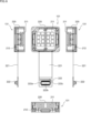
- FIG. 5 is an external perspective view of the multi-IMU 131
- the upper part of FIG. 6 is a side view, top view, and side view of the other from the left
- the lower part of FIG. 6 is a front view.
- the multi-IMU 131 is composed of a body part 220, a wiring part 221, and terminals 222.
- the main unit 220 has a configuration for detecting the angular velocity and acceleration of the main unit 111.
- FIG. 5 and 6 show an example in which 16 IMUs 211 are stacked in two layers, and a total of 32 IMUs 211 are configured. Further, the arithmetic block 212 is configured in the layer below the IMU 211 in FIG. 5 . Each IMU 211 detects the angular velocity and acceleration of the main body 111 and outputs them to the calculation block 212 .
- the computation block 212 integrates the detection results of the angular velocity and acceleration of the main body 111 supplied from each of the plurality of IMUs 211 , computes the current angular velocity and angular velocity of the main body 111 , and outputs them to the current position/orientation estimator 137 . Output.
- the calculation block 212 predicts the future acceleration and angular velocity of the image sensor 181 for a predetermined time based on the integrated current acceleration and angular velocity of the main body 111 , and outputs them to the future position/orientation detection section 132 .
- the calculation block 212 predicts the future acceleration and angular velocity of the image sensor 181 for a predetermined time from the control amount target value supplied from the drive control section 133 and the integrated current acceleration and angular velocity of the main body 111 .
- a coefficient for the acceleration is obtained by learning, and based on the obtained coefficient, the future acceleration of the main body 111 and the acceleration are predicted for a predetermined period of time.
- the calculation block 212 outputs the current acceleration and angular velocity of the main body 111 as the calculation result and the acceleration and angular velocity of the image sensor 181 in the future for a predetermined time through the wiring part 221 and the terminal 222, respectively. It outputs to the estimator 137 and the future position/orientation detector 132 , and acquires the control amount target value as prediction error feedback from the drive controller 133 .
- the terminal 222a supplies the current acceleration and angular velocity of the main body 111 to the current position/orientation estimating section 137
- the terminal 222b supplies the acceleration and angular velocity of the image sensor 181 in the future for a predetermined time to the future position/orientation detecting section 132.
- a terminal 222c for acquiring a controlled variable target value as prediction error feedback from the drive control unit 133.
- Terminals 222a, 222b, and 222c are terminals of communication standards such as SPI (Serial Peripheral Interface), I2C (Inter Integrated Circuits), I3C (Improved Inter Integrated Circuits), and UART (Universal Asynchronous Receiver/Transmitter). consists of SPI (Serial Peripheral Interface), I2C (Inter Integrated Circuits), I3C (Improved Inter Integrated Circuits), and UART (Universal Asynchronous Receiver/Transmitter). consists of SPI (Serial Peripheral Interface), I2C (Inter Integrated Circuits), I3C (Improved Inter Integrated Circuits), and UART (Universal Asynchronous Receiver/Transmitter). consists of SPI (Serial Peripheral Interface), I2C (Inter Integrated Circuits), I3C (Improved Inter Integrated Circuits), and UART (Universal Asynchronous Receiver/Transmitter). consists of SPI (Serial Peripheral Interface),
- terminals 222a, 222b, and 222c are denoted by lead wires, but the intention is that the corresponding pins are arranged at the positions where the lead wires are attached. Instead, the terminal 222 is shown to include each of the terminals 222a, 222b, and 222c.
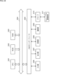
- the multi-IMU 131 is composed of IMUs 211-1 to 211-n and a computation block 212. That is, the IMUs 211-1 to 211-n correspond to the configuration shown as 32 square-shaped parts in FIGS.
- the calculation block 212 includes a synthesis processing unit 241, a short-term future prediction unit 242, output units 243-1 and 243-2, time stamp generation units 244-1 and 244-2, a prediction correction amount calculation unit 245, and a prediction learning unit. 246.
- the synthesis processing unit 241 acquires the angular velocity and acceleration of the main body 111 supplied from each of the IMUs 211-1 to 211-n, synthesizes them, and obtains one integrated current angular velocity and acceleration of the main body 111. It is output to the output unit 243-1 and the short-term future prediction unit 242 as acceleration.
- the short-term future prediction unit 242 performs calculations using coefficients generated by the prediction learning unit 246 learning the current angular velocity and acceleration of the main body unit 111 supplied from the synthesis processing unit 241. , the future angular velocity and acceleration of the image sensor 181 are predicted for a predetermined period of time and output to the output unit 243-2.
- the output unit 243-1 acquires the current angular velocity and acceleration of the main body unit 111 from the synthesizing unit 241, the output unit 243-1 adds a time stamp corresponding to the current time chronologically generated by the time stamp generation unit 244-1. , is output to the current position/orientation estimator 137 from the terminal 222a as a current output.
- the output unit 243-2 acquires the angular velocity and acceleration of the image sensor 181 for a predetermined time in the future from the short-term future prediction unit 242, the output unit 243-2 obtains the time for a predetermined time in the future generated in chronological order by the time stamp generation unit 244-2. , and output to the future position/orientation detection unit 132 from the terminal 222b as a prediction output.
- the prediction correction amount calculation unit 245 acquires the control amount target value supplied as prediction error feedback from the drive control unit 133, and predicts and corrects the angular velocity and acceleration corresponding to the position and orientation of the image sensor 181, which is the control amount target value. It is calculated as a quantity and output to prediction learning section 246 .
- the prediction learning unit 246 generates, through learning, coefficients necessary for predicting the future angular velocity and acceleration of the image sensor 181 for a predetermined time from the predicted correction amount and the current angular velocity and acceleration of the main body 111 . Output to the time future prediction unit 242 .
- the short-term future prediction unit 242 performs calculations using the coefficients generated in this manner and the current angular velocity and acceleration of the main body unit 111 supplied from the synthesis processing unit 241, thereby predicting the future image sensor 181 for a predetermined time. is predicted and output to the output unit 243-2.
- the coefficients used in the short-term future prediction unit 242 may be generated and stored in advance during manufacturing. In this case, the prediction correction amount calculation unit 245 and the prediction learning unit 246 may be omitted.
- the short-term future prediction unit 242 may be configured by, for example, a neural network.
- prediction learning section 246 performs machine learning using the prediction correction amount and the current angular velocity and acceleration of body section 111 to convert the input layer constituting short-term future prediction section 242 to the current angular velocity of body section 111 . and acceleration, and generates a hidden layer whose output layer is the angular velocity and acceleration of the image sensor 181 in the future for a predetermined time.
- the neural network used in the short-term future prediction unit 242 may be generated and stored in advance at the time of manufacture. In this case, the prediction correction amount calculation unit 245 and the prediction learning unit 246 may be omitted.
- the multi-IMU 131 including a plurality of IMUs 211 detects the angular velocity and acceleration of the main body 111 of the imaging device 101. Angular velocity and acceleration may be detected.
- the sensor position detection unit 182 in FIG. 8 is a so-called Hall element sensor, and is composed of magnets 251-1 and 251-2 and Hall elements 252-1 and 252-2.
- the magnets 251-1 and 251-2 are arranged so that their magnetization directions are aligned with the moving directions of the image sensor 181 in the vertical and horizontal directions.
- the Hall elements 252-1 and 252-2 are fixedly arranged so as to match the boundary between the S/N magnetic poles of the magnets 251-1 and 251-2 when the image sensor 181 is at the origin position. be done.
- the Hall elements 252-1 and 252-2 move about the boundaries of the S/N poles of the magnets 251-1 and 251-2.
- the applied magnetic field varies proportionally.
- the sensor position detection unit 182 shown in FIG. 8 can detect changes in position in the planar direction corresponding to the imaging surface of the image sensor 181, but cannot detect changes in the incident direction. Although not shown, this point can be dealt with by separately providing a magnet 251 and a Hall element 252 in the incident direction of the incident light.
- the sensor position detection unit 182 detects the amount of movement in each of the planar direction corresponding to the imaging surface of the image sensor 181 and the direction of incidence, and presents information on the detected amount of movement in the three-dimensional direction. It is supplied to the position/orientation detection unit 136 .
- the current position/orientation detection unit 136 detects the movement amount of the image sensor 181 based on the amount of movement in each of the three-dimensional directions in the planar direction corresponding to the imaging surface of the image sensor 181 and the incident direction, which are supplied from the sensor position detection unit 182 . Detect the position and orientation of
- an IMU is separately integrated with the image sensor 181, the IMU detects the angular velocity and acceleration of the image sensor 181, and the current position/orientation detection unit 136 detects with the IMU.
- the position and orientation of the image sensor 181 may be detected based on the obtained angular velocity and acceleration.
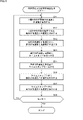
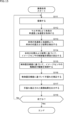
- step S11 the IMUs 211-1 to 211-n respectively detect the current acceleration and angular velocity of the main unit 111 and output them to the synthesis processing unit 241.
- step S12 the synthesizing unit 241 synthesizes the current acceleration and angular velocity of the main unit 111 detected by each of the IMUs 211-1 to 211-n, and outputs them to the short-term future prediction unit 242 and the output unit 243-1. Output.
- step S ⁇ b>13 the short-term future prediction unit 242 calculates the acceleration of the image sensor 181 for a predetermined time in the future based on the current acceleration and angular velocity of the main body 111 by calculation using the coefficients learned by the prediction learning unit 246 . and the angular velocity are predicted and output to the output unit 243-2.
- step S14 the output unit 243-1 adds a time stamp corresponding to the current time generated by the time stamp generation unit 244-1 to the current acceleration and angular velocity of the main unit 111 supplied from the synthesis processing unit 241. Give.
- step S15 the output unit 243-2 converts the acceleration and angular velocity of the main unit 111 a predetermined time in the future supplied from the short-term future prediction unit 242 into the future time generated by the time stamp generation unit 244-2. Give the corresponding timestamp.
- step S16 the output unit 243-1 outputs the current acceleration and angular velocity of the main body unit 111 to the current position/orientation estimation unit 137 as a current output along with the time stamp corresponding to the current time.
- step S17 the output unit 243-2 outputs the acceleration and angular velocity of the image sensor 181 for a predetermined time in the future to the future position/orientation detection unit 132 as a prediction output together with a time stamp corresponding to the future time.
- step S18 the composition processing unit 241 determines whether or not an instruction to end the process has been given, and if the end has not been given, the process returns to step S11.
- step S18 if the end of the process is instructed, the process ends.
- the current angular velocity and acceleration of the main body unit 111 are output to the current position/orientation estimation unit 137 as the current output with the time stamp corresponding to the current time added, and are output to the image sensor in the future for a predetermined time.
- the angular velocity and acceleration of 181 are output to the future position/orientation detection unit 132 as a prediction output with a time stamp corresponding to the future time.
- the current angular velocity and acceleration of the main body 111 to which the time stamp corresponding to the current time is given and the angular velocity and acceleration of the image sensor 181 in the future for a predetermined time to which the time stamp corresponding to the future time is given are combined. can be output.
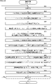
- step S ⁇ b>31 the image sensor 181 captures an image and stores the captured image in the image frame buffer 161 of the camera shake correction processing section 135 .
- step S ⁇ b>32 the current position/orientation estimation unit 137 acquires the current angular velocity and acceleration of the main unit 111 , which are the current outputs supplied from the multi-IMU 131 .
- step S ⁇ b>33 the current position/orientation estimation unit 137 estimates the current position and orientation of the image sensor 181 based on the current angular velocity and acceleration of the main body unit 111 .
- the orientation is output to prediction error calculation section 138 .
- step S34 the sensor position detection unit 182 detects the amount of movement in the three-dimensional direction for each of the planar direction corresponding to the imaging surface of the image sensor 181 and the direction of incidence, and presents the detected amount of movement information to the current position. It is supplied to the position/orientation detection unit 136 .
- step S35 the current position/orientation detection unit 136, based on the movement amount information for each of the plane direction corresponding to the imaging surface of the image sensor 181 and the incident direction, which is supplied from the sensor position detection unit 182, The position and orientation of image sensor 181 are detected and output to prediction error calculation section 138 .
- step S36 the prediction error calculation unit 138 estimates the current position and orientation of the image sensor 181 based on the angular velocity and acceleration detected by the multi-IMU 131, which are supplied from the current position and orientation estimation unit 137, and the current Based on the amount of movement in the three-dimensional direction in each of the plane direction corresponding to the imaging surface of the image sensor 181 and the incident direction, which is detected by the sensor position detection unit 182 and supplied from the position/orientation detection unit 136, A difference from the current position and orientation detection result (actual measurement result) of the image sensor 181 is calculated as a prediction error and output to the drive control unit 133 .
- step S37 the future position/orientation detection unit 132 acquires the predicted outputs of the angular velocity and acceleration of the image sensor 181 for a predetermined time in the future supplied from the multi-IMU 131.
- step S38 the future position/orientation detection unit 132 detects the future position and orientation of the image sensor 181 for a predetermined time based on the angular velocity and acceleration of the main unit 111 for a predetermined time from the multi-IMU 131, and detects the position and orientation of the image sensor 181 for a predetermined time. Output to the control unit 133 .
- step S ⁇ b>39 the drive control unit 133 controls the control amount target value calculation unit 151 to calculate the position and orientation of the image sensor 181 for a predetermined time in the future supplied from the future position/orientation detection unit 132 and the prediction error calculation. Based on the prediction error supplied from the unit 138, the position and orientation of the image sensor 181, which are the control amount target values, are calculated.
- step S40 the drive control unit 133 generates a control signal for controlling the drive of the drive unit 134 based on the control amount target value, supplies the control signal to the drive unit 134, and controls the drive of the drive unit 134. to drive the position and orientation of the image sensor 181 .
- the drive control unit 133 calculates the control amount target value based on the time stamp given to the angular velocity and acceleration that specify the future position and orientation of the image sensor 181 for a predetermined time.
- a control signal of the corresponding control amount target value is output to the driving section 134.
- step S41 the drive control unit 133 outputs the control amount target value to the multi-IMU 131 as error feedback.
- step S ⁇ b>42 the drive control unit 133 outputs the control amount target value to the camera shake correction processing unit 135 .
- the camera shake correction processing unit 135 corrects the image stored in the image frame buffer 161 by obtaining a motion vector for each pixel based on the time-series control amount target value and correcting the camera shake by signal processing. and output to the output unit 113 .
- the drive control unit 133 uses the timing corresponding to the time stamp given to the angular velocity and acceleration that specify the position and orientation of the image sensor 181 in the future for a predetermined time period, which is used to calculate the control amount target value.
- the corresponding control amount target value is output to camera shake correction processing section 135 . That is, since this is signal processing and almost no delay occurs, the delay associated with the operation of the drive unit 134 is not taken into consideration.
- step S43 the image recording unit 191 of the output unit 113 records the shake-corrected image. Also, the transmission unit 152 of the output unit 113 transmits the shake-corrected image. When the output unit 113 is composed of a display or the like, the output unit 113 displays an image that has undergone camera shake correction.
- step S44 it is determined whether or not an instruction to end the imaging process has been given, and if the end has not been given, the process returns to step S31.
- steps S31 to S44 are repeated until the end of the imaging process is instructed.
- step S44 if an instruction to end the imaging process is given, the process ends.
- the position and orientation of the image sensor 181 as the control amount target value are set, and the set control amount target value is obtained.
- the driving unit 134 drives the image sensor 181 so that the position and orientation are maintained.
- the position and orientation of the image sensor 181 that provide the target control amount are set in consideration of the delay based on the operation of the driving unit 134, and the position and orientation that provide the set target control amount are maintained. Therefore, it is possible to correct the shake of the image sensor 181 appropriately.
- a prediction that is the difference between the estimation result of the current position and orientation of the image sensor 181 estimated by the current output of the multi-IMU 131 and the actual measurement result of the position and orientation of the image sensor 181 detected by the sensor position detection unit 182 The error is taken into consideration when setting the controlled variable target value.
- control amount target value of the image sensor 181 is appropriately set in consideration of the deviation between the position and orientation of the main unit 111 detected by the multi-IMU 131 and the actual position and orientation of the image sensor 181. , and it is possible to correct the shake so as to maintain the position and orientation that correspond to the set control amount target value.
- the driving unit 134 is controlled according to the control amount target value set based on the future position and orientation of the image sensor 181 for a predetermined time, and the prediction error that still occurs is processed by the camera shake correction processing unit 135. Since the shake is electronically corrected in accordance with the control amount target value, highly accurate shake correction can be realized.
- the imaging device 101 mounted on the mobile device 100 such as a drone or vehicle suffers from camera shake caused by high-frequency vibrations of the drive motor, engine, etc. of the mobile device 100 (shake caused by high-frequency vibrations of the motor, engine, etc.). ) can also be corrected.
- step S ⁇ b>61 the predicted correction amount calculator 254 acquires the predicted error feedback consisting of the control amount target value supplied from the drive controller 133 .
- step S62 the predicted correction amount calculation unit 254 calculates the angular velocity and acceleration in the future for a predetermined time as predicted correction amounts based on the obtained control amount target values of the position and attitude of the image sensor 181, and the prediction learning unit 246 output to
- step S63 the prediction learning unit 246 obtains coefficients necessary for predicting future angular velocities and accelerations for a predetermined period of time as prediction correction amounts based on the current angular velocities and accelerations of the main body 111. Output to the prediction unit 242 .
- step S64 the prediction learning unit 246 determines whether or not an instruction to end is given, and if the instruction to end is not given, the process returns to step S61, and the subsequent processes are repeated.
- steps S61 to S64 are repeated until the end of the process is instructed, and based on the current angular velocity and acceleration of the main body 111, the angular velocity and acceleration necessary for predicting the future angular velocity and acceleration for a predetermined period of time.
- the learning process is repeated to obtain coefficients and hidden layers.
- step S64 when the end of the process is instructed, the process ends.
- the coefficients used in the short-term future prediction unit 242 for obtaining the angular velocity and acceleration of the image sensor 181 in the predicted predetermined time future based on the current angular velocity and acceleration of the main body unit 111 are By repeating the required learning, it becomes possible to detect the future angular velocity and acceleration for a predetermined period of time with higher accuracy.
- the multi-IMU 131 is operated for a short time. An example of learning the coefficients used by the future prediction unit 242 has been described.
- control amount target value is obtained from the error between the current angular velocity and acceleration of the main unit 111 detected in the multi-IMU 131 and the angular velocity and acceleration of the image sensor 181 in the future for a predetermined time, and the control amount target value is detected in the multi-IMU 131 for a short time.
- Coefficients used in the future prediction unit 242 may be learned. In this case, the multi-IMU 131 outputs only the future angular velocity and acceleration of the image sensor 181 for a predetermined time, which is the predicted output.
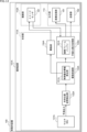
- FIG. 12 shows a configuration example of the second embodiment of the imaging device in which the coefficients used by the short-term future prediction unit 242 are learned within the multi-IMU 131 .
- a multi-IMU 131A is provided instead of the multi-IMU 131, and a current position/orientation detection unit 136, a current position/orientation estimation unit 137, and a prediction error calculation unit 138 are provided. , and the sensor position detector 182 are eliminated.
- the coefficients used in the short-term future prediction unit 242 are learned in the multi-IMU 131A.
- the portion 138 and the sensor position detection portion 182 are omitted.
- the multi-IMU 131A outputs only the future position and orientation information of the image sensor 181 for a predetermined time, which is a prediction output, to the future position and orientation detection unit 132 .
- the drive control unit 133A controls the control amount target value calculation unit 151A only from information on the position and orientation of the image sensor 181 in the future for a predetermined time, which is the predicted output supplied from the multi-IMU 131A. Calculate the target value.
- the same reference numerals are given to the configurations having the same functions as the configuration of the multi-IMU 131 of FIG. 5, and the description thereof will be omitted.
- the multi-IMU 131A of FIG. 13 differs from the multi-IMU 131 of FIG. is provided.
- the current position/orientation detection unit 261 has a configuration corresponding to the current position/orientation estimation unit 137 in FIG. , the current position and orientation of the image sensor 181 are detected (estimated) and output to the prediction error calculator 263 .
- the future position/orientation detection unit 262 corresponds to the future position/orientation detection unit 132A, and is output from the output unit 243-2, based on the angular velocity and acceleration of the image sensor 181 in the future for a predetermined time, which is the predicted output. , detects (estimates) the future position and orientation of the image sensor 181 for a predetermined period of time, and outputs them to the prediction error calculation section 263 and the control amount target value calculation section 264 .
- the current position/orientation detection unit 261 and the future position/orientation detection unit 262 detect (estimate) the position and orientation based on the detection results of the multi-IMU 131A.
- the current and future positions and orientations of the main body 111 are set, and in this example, the respective detection results are used as the estimation results of the position and orientation of the image sensor 181 .
- the prediction error calculation unit 263 has a configuration corresponding to the prediction error calculation unit 138 in FIG. is calculated as a prediction error and output to the control amount target value calculation unit 264 .
- the prediction error calculation unit 263 buffers the future position and orientation information of the image sensor 181 for a predetermined period of time, and calculates the difference from the current position and orientation information with the same time stamp as It is calculated as a prediction error and output to control amount target value calculation section 264 .
- the control amount target value calculation unit 264 corresponds to the control amount target value calculation unit 151A, and calculates the control amount target value of the image sensor 181 based on the information of the position and orientation of the image sensor 181 in the future for a predetermined time. calculated and output to the prediction correction amount calculation unit 245 as prediction error feedback. At this time, the control amount target value calculation section 264 calculates the control amount target value in consideration of the prediction error.
- the prediction error feedback output from the control amount target value calculation unit 264 corresponds to the prediction error feedback output from the drive control unit 133 in FIG.
- the prediction error feedback is generated within the multi-IMU 131A, and the short-term future prediction unit 242 generates the current angular velocity and acceleration based on the current angular velocity and acceleration. Then, coefficients for predicting future angular velocity and acceleration for a predetermined time are generated by learning.
- FIG. 13 shows an example in which there is a terminal 222a for outputting the current angular velocity and acceleration, but since the current angular velocity and acceleration are not output, the terminal 222a is also omitted. It is good also as a structure.
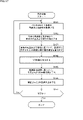
- steps S81 to S87 and S92 in the flowchart of FIG. 14 is the same as the processing of steps S11 to S18 in the flowchart of FIG. 9, so description thereof will be omitted.
- steps S81 to S87 the current angular velocity and acceleration and the future angular velocity and acceleration for a predetermined period of time are detected and output with time stamps added thereto. move on.
- step S ⁇ b>88 the current position/orientation detection unit 261 detects (estimates) the current position and orientation of the image sensor 181 based on the current angular velocity and acceleration, and outputs them to the prediction error calculation unit 263 .
- step S89 the future position/orientation detection unit 262 detects (estimates) the position and orientation of the image sensor 181 in the future for a predetermined period of time based on the angular velocity and acceleration in the future for the predetermined period of time. Output to the control amount target value calculation unit 264 .
- step S90 the prediction error calculation unit 263 calculates the current position and orientation of the image sensor 181 supplied from the current position/orientation detection unit 261 and the future image for a predetermined time supplied from the future position/orientation detection unit 262. A difference from the position and orientation of the sensor 181 is calculated and output to the control amount target value calculation unit 264 as a prediction error.
- step S91 the control amount target value calculation unit 264 calculates the position and orientation that are the control amount target values of the image sensor 181, and outputs them to the prediction correction amount calculation unit 245 as prediction error feedback. At this time, the control amount target value calculation section 264 calculates the control amount target value in consideration of the prediction error.
- the multi-IMU 131A learns coefficients for predicting future angular velocities and accelerations for a predetermined period of time based on the current angular velocities and accelerations without obtaining prediction error feedback from the imaging device 101. can be generated.
- Imaging processing by the imaging device 101 in FIG. 12 will be described with reference to the flowchart in FIG. 15 .
- step S ⁇ b>111 the image sensor 181 captures an image and stores the captured image in the image frame buffer 161 of the camera shake correction processing section 135 .
- step S112 the future position/orientation detection unit 132A acquires the future angular velocity and acceleration of the image sensor 181 for a predetermined time, which is the predicted output supplied from the multi-IMU 131A.
- step S113 the future position/orientation detection unit 132 detects the position and orientation of the image sensor 181 in the future for a predetermined period of time based on the angular velocity and acceleration of the image sensor 181 in the future for the predetermined period of time from the multi-IMU 131A. Output to the control unit 133A.
- step S114 the drive control unit 133A controls the control amount target value calculation unit 151A to generate an image based on the position and orientation of the image sensor 181 in the future for a predetermined time, supplied from the future position/orientation detection unit 132A.
- the position and orientation of the sensor 181, which are the control amount target values, are calculated.
- step S115 the drive control unit 133A controls the driving of the drive unit 134A based on the control amount target value, and controls the image sensor 181 so as to maintain the state of the position and orientation corresponding to the control amount target value.
- step S116 the drive control unit 133A outputs the control amount target value to the camera shake correction processing unit 135A.
- the camera-shake correction processing unit 135A corrects the image stored in the image frame buffer 161A by signal processing based on the control amount target value, performs camera-shake correction, and outputs the image to the output unit 113 .
- step S117 the image recording unit 191 of the output unit 113 records the shake-corrected image. Also, the transmission unit 152 of the output unit 113 transmits the shake-corrected image. When the output unit 113 is a display unit, the output unit 113 displays an image that has undergone camera shake correction.
- step S118 it is determined whether or not an instruction to end the imaging process has been given, and if the end has not been given, the process returns to step S111.
- steps S111 to S118 are repeated until the end of the imaging process is instructed.
- step S118 if an instruction to end the imaging process is given, the process ends.
- prediction error feedback is generated in the multi-IMU 131A, and coefficients for predicting future angular velocities and accelerations for a predetermined period of time are learned in the short-term future prediction unit 242 based on the current angular velocities and accelerations.
- a value is set, and driving of the driving unit 134A is controlled based on the set control amount target value, whereby the image sensor 181 is controlled to maintain the position and posture that become the control amount target value. becomes possible.
- the position and attitude of the image sensor 181 are controlled in consideration of the delay based on the operation of the drive unit 134, so that the shake of the image sensor 181 can be appropriately corrected.
- generation of prediction error feedback is not required, so the configuration of the imaging device 101A can be made simple.
- the position and attitude of the image sensor 181 can be controlled in consideration of the operation delay caused by the drive unit 134A, and the vibration can be corrected. can be realized.
- the multi-IMU 131A is used to explain the example of realizing camera shake correction at the time of shooting. , so-called VR motion sickness prevention processing may be realized.
- the VR goggles device is a device worn on the user's head, and the display unit is provided at a position facing the front of the user's eyes. The image is what is displayed.
- the multi-IMU of the present disclosure in the VR glasses device, by predicting the future movement of the VR glasses device for a predetermined time and changing the VR image and displaying it, the occurrence of VR sickness is prevented. You can let it run.
- FIG. 16 shows a configuration example of a VR glasses device to which the multi-IMU 131A used in the imaging device 101A of FIG. 12 is applied.
- the VR glasses device 301 shown in FIG. 16 is a device provided with a glasses-like display unit composed of organic EL (Electro Luminescence), LCD (Liquid Crystal Display), or the like. It is worn on the user's head while facing the , and a VR image corresponding to the movement of the user's head is displayed on the display unit.
- a glasses-like display unit composed of organic EL (Electro Luminescence), LCD (Liquid Crystal Display), or the like. It is worn on the user's head while facing the , and a VR image corresponding to the movement of the user's head is displayed on the display unit.
- the VR glasses device 301 is composed of a multi-IMU 311, a future position/orientation detection unit 312, a drive control unit 313, a shake correction unit 314, an image generation unit 315, and a display unit 318.
- the multi-IMU 311 has the same configuration as the multi-IMU 131A in FIG. It should be noted that the predetermined time from the present, which is the future here, is the time corresponding to the processing time until the VR image is changed and displayed.
- the future position/orientation detection unit 312 has a configuration corresponding to the future position/orientation detection unit 132A in FIG. , the future position and orientation of the head on which the VR glasses device 301 is worn is detected for a predetermined period of time, and output to the drive control unit 313 .
- the drive control unit 313 includes a control amount target value calculation unit 351 , and controls the control amount target value calculation unit 351 to detect the future position and position of the head supplied from the future position/orientation detection unit 312 for a predetermined time. Based on the orientation information, a control amount target value specifying the position and orientation of the VR image to be displayed on the VR glasses device 301 is calculated and output to the shake correction unit 314 .
- the shake correction unit 314 causes the VR glasses device 301 to display a VR image whose position and orientation correspond to the control amount target value for the image displayed on the display unit 316 generated by the image generation unit 315 .
- the shake is corrected by applying electronic rotation and translation.
- the shake correction unit 314 changes the position and orientation of the head of the user wearing the corresponding VR glasses device 301 (change in line-of-sight direction) based on the future position and orientation of the VR glasses device 301 for a predetermined period of time. Correct the VR image so that it can be viewed without shaking.
- the image generation unit 315 generates a VR image as a display image, and after the blurring of the VR image is corrected by the shake correction unit 314, it is displayed on a display such as an organic EL (Electro Luminescence) or an LCD (Liquid Crystal Display). Output to the unit 318 for display.
- a display such as an organic EL (Electro Luminescence) or an LCD (Liquid Crystal Display).
- the display of the VR image displayed on the display unit 318 is corrected for the future movement of the head on which the VR glasses device 301 is worn for a predetermined period of time. , it is possible to suppress VR motion sickness caused by the display delay of the shake-corrected VR image.
- step S ⁇ b>151 the multi-IMU 311 detects the future angular velocity and acceleration for a predetermined period of time of the VR glasses device through angular velocity and acceleration detection processing, and outputs them to the future position/orientation detection unit 312 .
- the angular velocity and acceleration detection processing is the same as the processing described with reference to the flowchart of FIG. 14, so description thereof will be omitted.
- the future position/orientation detection unit 312 acquires the angular velocity and acceleration of the VR glasses device 301 in the future for a predetermined time, supplied from the multi-IMU 311 .
- step S152 the future position/orientation detection unit 312 detects the position and orientation of the VR glasses device 301 in the future for a predetermined time based on the angular velocity and acceleration of the VR glasses device 301 in the future for a predetermined time from the multi-IMU 311. , to the drive control unit 313 .
- step S153 the drive control unit 313 controls the control amount target value calculation unit 351, and based on the future position and orientation of the VR glasses device 301 for a predetermined time, supplied from the future position/orientation detection unit 312, The position and orientation of the control amount target value for displaying the VR image to be displayed on the display unit 316 are calculated and output to the shake correction unit 314 .
- step S154 the image generation unit 315 generates a VR image to be displayed on the display unit 316.
- step S155 the shake correction unit 314 performs shake correction by displaying on the display unit 316, rotating the image generated by the image generation unit 315, or translating it based on the control amount target value. .
- step S156 the image generator 315 outputs to the display unit 316 the VR image that has been shake-corrected by the shake corrector 314 so as to maintain the position and orientation at which the VR image serving as the control amount target value is displayed. display.
- step S157 it is determined whether or not an instruction to end the display process has been given, and if the end has not been given, the process returns to step S151.
- steps S151 to S157 are repeated until the end of the imaging process is instructed.
- step S157 if an instruction to end the display process is given, the process ends.
- the future position and orientation of the VR glasses device 301 worn on the head are detected for a predetermined period of time, and based on the detected future position and orientation of the VR glasses device 301 for the predetermined period of time, the display unit
- the VR image displayed in 316 can be displayed with shake correction applied so as to maintain the displayed position and posture.
- the motion of the VR glasses device 301 in the future that is, the motion of the user's head, is corrected to correct the shake that occurs in the displayed VR image, thereby suppressing the so-called VR motion sickness. becomes possible.
- the series of processes described above can be executed by hardware, but can also be executed by software.
- the programs that make up the software are installed in a computer built into dedicated hardware, or various programs are installed to execute various functions. installed from a recording medium on, for example, a general-purpose computer.
- FIG. 18 shows a configuration example of a general-purpose computer.
- This personal computer incorporates a CPU (Central Processing Unit) 1001 .
- An input/output interface 1005 is connected to the CPU 1001 via a bus 1004 .
- a ROM (Read Only Memory) 1002 and a RAM (Random Access Memory) 1003 are connected to the bus 1004 .
- the input/output interface 1005 includes an input unit 1006 including input devices such as a keyboard and a mouse for the user to input operation commands, an output unit 1007 for outputting a processing operation screen and images of processing results to a display device, and programs and various data.
- LAN Local Area Network
- magnetic discs including flexible discs
- optical discs including CD-ROM (Compact Disc-Read Only Memory), DVD (Digital Versatile Disc)), magneto-optical discs (including MD (Mini Disc)), or semiconductors
- a drive 1010 that reads and writes data from a removable storage medium 1011 such as a memory is connected.
- the CPU 1001 reads a program stored in the ROM 1002 or a removable storage medium 1011 such as a magnetic disk, an optical disk, a magneto-optical disk, or a semiconductor memory, installs the program in the storage unit 1008, and loads the RAM 1003 from the storage unit 1008. Various processes are executed according to the program.
- the RAM 1003 also appropriately stores data necessary for the CPU 1001 to execute various processes.
- the CPU 1001 loads, for example, a program stored in the storage unit 1008 into the RAM 1003 via the input/output interface 1005 and the bus 1004, and executes the above-described series of programs. is processed.
- a program executed by the computer (CPU 1001) can be provided by being recorded on a removable storage medium 1011 such as a package medium, for example. Also, the program can be provided via a wired or wireless transmission medium such as a local area network, the Internet, or digital satellite broadcasting.
- the program can be installed in the storage section 1008 via the input/output interface 1005 by loading the removable storage medium 1011 into the drive 1010 . Also, the program can be received by the communication unit 1009 and installed in the storage unit 1008 via a wired or wireless transmission medium. In addition, programs can be installed in the ROM 1002 and the storage unit 1008 in advance.
- the program executed by the computer may be a program that is processed in chronological order according to the order described in this specification, or may be executed in parallel or at a necessary timing such as when a call is made. It may be a program in which processing is performed.
- the CPU 1001 in FIG. 18 controls the drive control unit 133 and the shake correction processing unit 135 in FIG. 4, the drive control unit 133A and the shake correction processing unit 135A in FIG. 12, and the drive control unit 313 and the shake correction unit 314 in FIG. Realize the function.
- a system means a set of multiple components (devices, modules (parts), etc.), and it does not matter whether all the components are in the same housing. Therefore, a plurality of devices housed in separate housings and connected via a network, and a single device housing a plurality of modules in one housing, are both systems. .
- the present disclosure can take the configuration of cloud computing in which a single function is shared by multiple devices via a network and processed jointly.
- each step described in the flowchart above can be executed by a single device, or can be shared by a plurality of devices.
- one step includes multiple processes
- the multiple processes included in the one step can be executed by one device or shared by multiple devices.
- an IMU Inertial Measurement Unit
- an inertial measurement device comprising: a prediction unit that predicts future angular velocity and acceleration for a predetermined period of time based on the current angular velocity and acceleration detected by the IMU.
- the prediction unit predicts the future angular velocity and acceleration by calculation using a predetermined coefficient for the current angular velocity and acceleration.
- ⁇ 3> a current position/orientation detection unit that detects the current position and orientation based on the current angular velocity and acceleration; a future position/orientation detection unit that detects the future position and orientation based on the future angular velocity and acceleration;
- ⁇ 4> The inertial measurement device according to ⁇ 1>, wherein the prediction unit is configured by a neural network having the current angular velocity and acceleration as an input layer and the future angular velocity and acceleration as an output layer.
- ⁇ 5> a current position/orientation detection unit that detects the current position and orientation based on the current angular velocity and acceleration; a future position/orientation detection unit that detects the future position and orientation based on the future angular velocity and acceleration;
- the inertial measurement device further comprising a learning unit that generates the neural network by machine learning based on a prediction error that is a difference between the current position and orientation and the future position and orientation.
- ⁇ 6> a future output unit that outputs the future angular velocity and acceleration; further comprising a current output unit that outputs the current angular velocity and acceleration; The current output unit outputs the current angular velocity and acceleration with a time stamp corresponding to the current time,
- the inertial measurement device according to ⁇ 1>, wherein the future output unit outputs the future angular velocity and acceleration with a time stamp corresponding to the future time for the predetermined time.
- the current output unit and the future output unit output the current angular velocity and acceleration, and the future angular velocity and acceleration via terminals of a predetermined communication standard, respectively Inertia according to ⁇ 6> measuring device.
- the predetermined communication standard includes SPI (Serial Peripheral Interface), I2C (Inter Integrated Circuits), I3C (Improved Inter Integrated Circuits), and UART (Universal Asynchronous Receiver/Transmitter) Inertia according to ⁇ 7> measuring device.
- SPI Serial Peripheral Interface
- I2C Inter Integrated Circuits
- I3C Improved Inter Integrated Circuits
- UART Universal Asynchronous Receiver/Transmitter
- a method of operating an inertial measurement device having an IMU (Inertial Measurement Unit) that detects current angular velocity and acceleration A method of operating an inertial measurement unit, comprising predicting a future angular velocity and acceleration for a predetermined period of time based on the current angular velocity and acceleration detected by the IMU.
- an image sensor for capturing an image; a driving unit for driving the image sensor; an inertial measurement unit that detects the future angular velocity and acceleration of the image sensor for a predetermined time; a future position/orientation detection unit that detects a future position and orientation of the image sensor based on the future angular velocity and acceleration; a drive control unit that controls to drive the drive unit so as to correct shake of the image sensor based on the future position and orientation of the image sensor;
- the inertial measurement unit an IMU (Inertial Measurement Unit) that detects the current angular velocity and acceleration of the main body; and a prediction unit that predicts future angular velocity and acceleration for a predetermined time based on the current angular velocity and acceleration detected by the IMU.
- IMU Inertial Measurement Unit
- the drive control unit calculates a position and orientation as a control amount target value of the image sensor based on the future position and orientation of the image sensor, and generates a control signal based on the control amount target value. supplied to the drive unit;
- the image capturing apparatus according to ⁇ 12>, wherein the driving unit drives the image sensor so as to maintain a position and an orientation corresponding to the control amount target value based on the control signal.
- the drive control unit feeds back the control amount target value to the inertia measurement unit
- the prediction unit predicts future angular velocities and accelerations for a predetermined period of time by performing processing using predetermined coefficients on the current angular velocities and accelerations detected by the IMU,
- the imaging device according to ⁇ 13>, wherein the inertial measurement unit further includes a learning unit that learns the predetermined coefficient based on the control amount target value.
- the inertial measurement unit a future output unit that outputs the future angular velocity and acceleration; a current output unit that outputs the current angular velocity and acceleration; a current position/orientation estimation unit that estimates the current position and orientation of the image sensor based on the current angular velocity and acceleration output from the current output unit; a position and orientation detection unit that detects the position and orientation of the image sensor driven by the drive unit; a prediction error calculation unit configured to calculate, as a prediction error, a difference between the position and orientation of the image sensor as the result of estimation by the current position and orientation estimation unit and the position and orientation of the image sensor detected by the position and orientation detection unit; further comprising The image pickup apparatus according to ⁇ 14>, wherein the drive control unit calculates a position and orientation of the image sensor as a control amount target value based on the future position and orientation of the image sensor and the prediction error.
- the imaging apparatus further including a shake correction unit that applies shake correction by signal processing to the image captured by the image sensor based on the control amount target value.
- the prediction unit predicts the future angular velocity and acceleration by performing processing using a predetermined coefficient on the current angular velocity and acceleration detected by the IMU,
- the inertial measurement unit a current position/orientation detection unit that detects the current position and orientation of the image sensor based on the current angular velocity and acceleration; another future position/orientation detection unit, different from the future position/orientation detection unit, for detecting the future position and orientation of the image sensor based on the future angular velocity and acceleration; Prediction error calculation for calculating, as a prediction error, a difference between the current position and orientation detected by the current position and orientation detection unit and the future position and orientation detected by the other future position and orientation detection unit.
- the imaging apparatus further comprising a learning unit that learns the predetermined coefficient based on the control amount target value.
- a display unit that displays an image that can be viewed by the user when worn in front of the user's head; an inertial measurement unit that detects future angular velocity and acceleration of the head for a predetermined period of time; a future position/orientation detection unit that detects a future position and orientation of the head based on the future angular velocity and acceleration; a shake correction unit that corrects shake of the image displayed on the display unit based on the future position and orientation of the head;
- the inertial measurement unit an IMU (Inertial Measurement Unit) that detects the current angular velocity and acceleration; a prediction unit that predicts future angular velocity and acceleration for a predetermined time based on the current angular velocity and acceleration detected by the IMU.
- IMU Inertial Measurement Unit
- ⁇ 19> further comprising a control amount target value calculation unit that calculates a control amount target value for the position and orientation of the image displayed on the display unit based on the future position and orientation;
- the display device according to ⁇ 18> wherein the shake correcting section corrects the shake so that the image is displayed at a position and orientation corresponding to the control amount target value.
- the display unit displays a VR (Virtual Reality) image as the image.
- 100 mobile device 101 imaging device, 111 main unit, 112 imaging unit, 113 output unit, 131 multi-IMU, 132 future position/orientation detection unit, 133 drive control unit, 134 drive unit, 135 camera shake correction processing unit, 136 current position Posture detection unit, 137 current position/posture estimation unit, 138 prediction error calculation unit, 151 control amount target value calculation unit, 161 image frame buffer, 181 image sensor, 182 sensor position detection unit, 191 image recording unit, 192 transmission unit, 211 , 211-1 to 211-n IMU, 212 operation block, 241 synthesis processing unit, 242 short-term future prediction unit, 243-1, 243-2 output unit, 244-1, 244-2 time stamp generation unit, 245 prediction Correction amount calculation unit, 246 prediction learning unit, 101A imaging device, 111A main unit, 131A multi-IMU, 132A future position/orientation detection unit, 133A drive control unit, 134A drive unit, 135A camera shake correction processing unit, 151A control amount target value calculation Section
Landscapes
- Engineering & Computer Science (AREA)
- Physics & Mathematics (AREA)
- Radar, Positioning & Navigation (AREA)
- Remote Sensing (AREA)
- General Physics & Mathematics (AREA)
- Multimedia (AREA)
- Signal Processing (AREA)
- Automation & Control Theory (AREA)
- Optics & Photonics (AREA)
- Studio Devices (AREA)
Priority Applications (4)
| Application Number | Priority Date | Filing Date | Title |
|---|---|---|---|
| EP22848873.0A EP4379460A4 (en) | 2021-07-28 | 2022-02-25 | Inertial measurement unit, method for operating inertial measurement unit, imaging device, display device, and program |
| CN202280050866.6A CN117677894A (zh) | 2021-07-28 | 2022-02-25 | 惯性测量装置、操作惯性测量装置的方法、成像装置、显示装置和程序 |
| US18/580,072 US20240328790A1 (en) | 2021-07-28 | 2022-02-25 | Inertial measurement device, method of operating inertial measurement device, imaging device, display device, and program |
| JP2023538227A JPWO2023007789A1 (https=) | 2021-07-28 | 2022-02-25 |
Applications Claiming Priority (2)
| Application Number | Priority Date | Filing Date | Title |
|---|---|---|---|
| JP2021122932 | 2021-07-28 | ||
| JP2021-122932 | 2021-07-28 |
Publications (1)
| Publication Number | Publication Date |
|---|---|
| WO2023007789A1 true WO2023007789A1 (ja) | 2023-02-02 |
Family
ID=85086587
Family Applications (1)
| Application Number | Title | Priority Date | Filing Date |
|---|---|---|---|
| PCT/JP2022/007795 Ceased WO2023007789A1 (ja) | 2021-07-28 | 2022-02-25 | 慣性計測装置、および慣性計測装置の作動方法、撮像装置、表示装置、並びにプログラム |
Country Status (5)
| Country | Link |
|---|---|
| US (1) | US20240328790A1 (https=) |
| EP (1) | EP4379460A4 (https=) |
| JP (1) | JPWO2023007789A1 (https=) |
| CN (1) | CN117677894A (https=) |
| WO (1) | WO2023007789A1 (https=) |
Cited By (1)
| Publication number | Priority date | Publication date | Assignee | Title |
|---|---|---|---|---|
| US20230110992A1 (en) * | 2021-10-12 | 2023-04-13 | Canon Kabushiki Kaisha | Information processing apparatus, control method of information processing apparatus, and storage medium |
Families Citing this family (3)
| Publication number | Priority date | Publication date | Assignee | Title |
|---|---|---|---|---|
| EP4174570A4 (en) * | 2020-06-30 | 2024-01-03 | Sony Group Corporation | SOLID STATE IMAGING ELEMENT, IMAGING DEVICE, METHOD FOR OPERATING AN IMAGING DEVICE, MOBILE OBJECT, METHOD FOR OPERATING A MOBILE OBJECT DEVICE AND PROGRAM |
| WO2023188044A1 (ja) * | 2022-03-29 | 2023-10-05 | キヤノン株式会社 | 撮像装置およびその制御方法、および画像処理装置および方法 |
| CN118232781B (zh) * | 2024-05-27 | 2024-07-26 | 秦皇岛达则机电设备有限公司 | 一种基于实时控制系统的直线电机控制方法 |
Citations (8)
| Publication number | Priority date | Publication date | Assignee | Title |
|---|---|---|---|---|
| JP2011095467A (ja) | 2009-10-29 | 2011-05-12 | Panasonic Corp | 像ブレ補正装置、レンズ鏡筒、撮像装置本体、及び、撮像装置 |
| JP2014138380A (ja) | 2013-01-18 | 2014-07-28 | Toyota Motor Corp | 車両不正状態検出方法、車載システムにおける制御方法、およびシステム |
| WO2015012076A1 (ja) * | 2013-07-22 | 2015-01-29 | オリンパス株式会社 | 像ブレ補正装置及び撮像装置 |
| JP2018013602A (ja) * | 2016-07-21 | 2018-01-25 | キヤノン株式会社 | 像ブレ補正装置、レンズ装置、撮像装置、および、撮像システム |
| JP2018017756A (ja) * | 2016-07-25 | 2018-02-01 | キヤノン株式会社 | 制御装置、撮像装置、レンズ装置、制御方法、プログラム、および、記憶媒体 |
| JP2019121941A (ja) * | 2018-01-09 | 2019-07-22 | ソニーセミコンダクタソリューションズ株式会社 | 画像処理装置および方法、並びに画像処理システム |
| WO2020045099A1 (ja) | 2018-08-28 | 2020-03-05 | ソニー株式会社 | 情報処理装置および情報処理方法、並びにプログラム |
| WO2021065630A1 (ja) * | 2019-09-30 | 2021-04-08 | 株式会社ソニー・インタラクティブエンタテインメント | 画像データ転送装置および画像データ転送方法 |
Family Cites Families (6)
| Publication number | Priority date | Publication date | Assignee | Title |
|---|---|---|---|---|
| JP3380402B2 (ja) * | 1996-08-07 | 2003-02-24 | シャープ株式会社 | 撮像装置 |
| CN108664122A (zh) * | 2018-04-04 | 2018-10-16 | 歌尔股份有限公司 | 一种姿态预测方法和装置 |
| US10771698B2 (en) * | 2018-08-31 | 2020-09-08 | Qualcomm Incorporated | Image stabilization using machine learning |
| US11077850B2 (en) * | 2019-09-06 | 2021-08-03 | Lyft, Inc. | Systems and methods for determining individualized driving behaviors of vehicles |
| US11269329B2 (en) * | 2019-10-21 | 2022-03-08 | Baidu Usa Llc | Dynamic model with learning based localization correction system |
| US11827237B2 (en) * | 2019-12-27 | 2023-11-28 | Toyota Connected North America, Inc. | Systems and methods for real-time crash detection using telematics data |
-
2022
- 2022-02-25 US US18/580,072 patent/US20240328790A1/en active Pending
- 2022-02-25 CN CN202280050866.6A patent/CN117677894A/zh active Pending
- 2022-02-25 EP EP22848873.0A patent/EP4379460A4/en active Pending
- 2022-02-25 JP JP2023538227A patent/JPWO2023007789A1/ja active Pending
- 2022-02-25 WO PCT/JP2022/007795 patent/WO2023007789A1/ja not_active Ceased
Patent Citations (8)
| Publication number | Priority date | Publication date | Assignee | Title |
|---|---|---|---|---|
| JP2011095467A (ja) | 2009-10-29 | 2011-05-12 | Panasonic Corp | 像ブレ補正装置、レンズ鏡筒、撮像装置本体、及び、撮像装置 |
| JP2014138380A (ja) | 2013-01-18 | 2014-07-28 | Toyota Motor Corp | 車両不正状態検出方法、車載システムにおける制御方法、およびシステム |
| WO2015012076A1 (ja) * | 2013-07-22 | 2015-01-29 | オリンパス株式会社 | 像ブレ補正装置及び撮像装置 |
| JP2018013602A (ja) * | 2016-07-21 | 2018-01-25 | キヤノン株式会社 | 像ブレ補正装置、レンズ装置、撮像装置、および、撮像システム |
| JP2018017756A (ja) * | 2016-07-25 | 2018-02-01 | キヤノン株式会社 | 制御装置、撮像装置、レンズ装置、制御方法、プログラム、および、記憶媒体 |
| JP2019121941A (ja) * | 2018-01-09 | 2019-07-22 | ソニーセミコンダクタソリューションズ株式会社 | 画像処理装置および方法、並びに画像処理システム |
| WO2020045099A1 (ja) | 2018-08-28 | 2020-03-05 | ソニー株式会社 | 情報処理装置および情報処理方法、並びにプログラム |
| WO2021065630A1 (ja) * | 2019-09-30 | 2021-04-08 | 株式会社ソニー・インタラクティブエンタテインメント | 画像データ転送装置および画像データ転送方法 |
Non-Patent Citations (1)
| Title |
|---|
| See also references of EP4379460A4 |
Cited By (2)
| Publication number | Priority date | Publication date | Assignee | Title |
|---|---|---|---|---|
| US20230110992A1 (en) * | 2021-10-12 | 2023-04-13 | Canon Kabushiki Kaisha | Information processing apparatus, control method of information processing apparatus, and storage medium |
| US12347133B2 (en) * | 2021-10-12 | 2025-07-01 | Canon Kabushiki Kaisha | Information processing apparatus, control method of information processing apparatus, and storage medium |
Also Published As
| Publication number | Publication date |
|---|---|
| CN117677894A (zh) | 2024-03-08 |
| EP4379460A1 (en) | 2024-06-05 |
| EP4379460A4 (en) | 2024-11-06 |
| US20240328790A1 (en) | 2024-10-03 |
| JPWO2023007789A1 (https=) | 2023-02-02 |
Similar Documents
| Publication | Publication Date | Title |
|---|---|---|
| WO2023007789A1 (ja) | 慣性計測装置、および慣性計測装置の作動方法、撮像装置、表示装置、並びにプログラム | |
| JP6098874B2 (ja) | 撮像装置および画像処理装置 | |
| US11412142B2 (en) | Translation correction for optical image stabilization | |
| TWI533692B (zh) | 使用影像穩定校正捲動快門 | |
| JP6209002B2 (ja) | 撮像装置およびその制御方法 | |
| KR101856947B1 (ko) | 촬영장치, 움직임 추정장치, 영상 보정 방법, 움직임 추정방법 및 컴퓨터 판독가능 기록매체 | |
| US9013585B2 (en) | Image capture device | |
| US20170085740A1 (en) | Systems and methods for storing images and sensor data | |
| TW201303795A (zh) | 用於影像穩定之方法及系統 | |
| US10216002B2 (en) | Anti-shake correction system for curved optical sensor | |
| US20140063271A1 (en) | Image capture device and image processor | |
| US10412306B1 (en) | Optical image stabilization method and apparatus | |
| JP2017147682A (ja) | 全天球撮影システム | |
| US12250458B2 (en) | Integrated visual-inertial odometry and image stabilization for image processing | |
| US20250080846A1 (en) | Imaging apparatus | |
| US9270884B2 (en) | Imaging apparatus and detecting apparatus | |
| US12289536B2 (en) | Systems and methods for capturing stabilized images | |
| US20230417553A1 (en) | Orientation calculation apparatus, orientation calculation method, imaging apparatus including orientation calculation apparatus, and method for controlling same | |
| WO2023113991A1 (en) | Systems and methods for capturing stabilized images | |
| JP2025005680A (ja) | 姿勢情報取得装置、撮像装置、及び姿勢情報取得方法 | |
| JP7734074B2 (ja) | 制御装置、撮像装置、制御方法、制御プログラム | |
| US20260101111A1 (en) | Control apparatus, imaging movable unit, control method, and storage medium | |
| JP7209107B2 (ja) | 撮像支援装置、撮像装置、撮像システム、撮像支援システム、撮像支援方法、及びプログラム | |
| CN120881391A (zh) | 光学防抖方法、装置及电子设备 | |
| CN121982182A (en) | Virtual image display method, device, chip and storage medium |
Legal Events
| Date | Code | Title | Description |
|---|---|---|---|
| 121 | Ep: the epo has been informed by wipo that ep was designated in this application |
Ref document number: 22848873 Country of ref document: EP Kind code of ref document: A1 |
|
| WWE | Wipo information: entry into national phase |
Ref document number: 2023538227 Country of ref document: JP |
|
| WWE | Wipo information: entry into national phase |
Ref document number: 18580072 Country of ref document: US |
|
| WWE | Wipo information: entry into national phase |
Ref document number: 202280050866.6 Country of ref document: CN |
|
| WWE | Wipo information: entry into national phase |
Ref document number: 2022848873 Country of ref document: EP |
|
| NENP | Non-entry into the national phase |
Ref country code: DE |
|
| ENP | Entry into the national phase |
Ref document number: 2022848873 Country of ref document: EP Effective date: 20240228 |