WO2023002925A1 - 容器、容器の製造方法、容器の製造装置、シールバーおよびフィルム組立体 - Google Patents
容器、容器の製造方法、容器の製造装置、シールバーおよびフィルム組立体 Download PDFInfo
- Publication number
- WO2023002925A1 WO2023002925A1 PCT/JP2022/027770 JP2022027770W WO2023002925A1 WO 2023002925 A1 WO2023002925 A1 WO 2023002925A1 JP 2022027770 W JP2022027770 W JP 2022027770W WO 2023002925 A1 WO2023002925 A1 WO 2023002925A1
- Authority
- WO
- WIPO (PCT)
- Prior art keywords
- film
- tear strip
- base
- container
- strip
- Prior art date
- Legal status (The legal status is an assumption and is not a legal conclusion. Google has not performed a legal analysis and makes no representation as to the accuracy of the status listed.)
- Ceased
Links
Images








Classifications
-
- B—PERFORMING OPERATIONS; TRANSPORTING
- B65—CONVEYING; PACKING; STORING; HANDLING THIN OR FILAMENTARY MATERIAL
- B65D—CONTAINERS FOR STORAGE OR TRANSPORT OF ARTICLES OR MATERIALS, e.g. BAGS, BARRELS, BOTTLES, BOXES, CANS, CARTONS, CRATES, DRUMS, JARS, TANKS, HOPPERS, FORWARDING CONTAINERS; ACCESSORIES, CLOSURES, OR FITTINGS THEREFOR; PACKAGING ELEMENTS; PACKAGES
- B65D75/00—Packages comprising articles or materials partially or wholly enclosed in strips, sheets, blanks, tubes or webs of flexible sheet material, e.g. in folded wrappers
- B65D75/52—Details
- B65D75/58—Opening or contents-removing devices added or incorporated during package manufacture
- B65D75/66—Inserted or applied tearing-strings or like flexible elements
-
- B—PERFORMING OPERATIONS; TRANSPORTING
- B65—CONVEYING; PACKING; STORING; HANDLING THIN OR FILAMENTARY MATERIAL
- B65D—CONTAINERS FOR STORAGE OR TRANSPORT OF ARTICLES OR MATERIALS, e.g. BAGS, BARRELS, BOTTLES, BOXES, CANS, CARTONS, CRATES, DRUMS, JARS, TANKS, HOPPERS, FORWARDING CONTAINERS; ACCESSORIES, CLOSURES, OR FITTINGS THEREFOR; PACKAGING ELEMENTS; PACKAGES
- B65D75/00—Packages comprising articles or materials partially or wholly enclosed in strips, sheets, blanks, tubes or webs of flexible sheet material, e.g. in folded wrappers
- B65D75/52—Details
- B65D75/58—Opening or contents-removing devices added or incorporated during package manufacture
- B65D75/5827—Tear-lines provided in a wall portion
- B65D75/5833—Tear-lines provided in a wall portion for tearing out a portion of the wall
- B65D75/5838—Tear-lines provided in a wall portion for tearing out a portion of the wall combined with separate fixed tearing means, e.g. tabs
-
- B—PERFORMING OPERATIONS; TRANSPORTING
- B65—CONVEYING; PACKING; STORING; HANDLING THIN OR FILAMENTARY MATERIAL
- B65D—CONTAINERS FOR STORAGE OR TRANSPORT OF ARTICLES OR MATERIALS, e.g. BAGS, BARRELS, BOTTLES, BOXES, CANS, CARTONS, CRATES, DRUMS, JARS, TANKS, HOPPERS, FORWARDING CONTAINERS; ACCESSORIES, CLOSURES, OR FITTINGS THEREFOR; PACKAGING ELEMENTS; PACKAGES
- B65D75/00—Packages comprising articles or materials partially or wholly enclosed in strips, sheets, blanks, tubes or webs of flexible sheet material, e.g. in folded wrappers
- B65D75/52—Details
- B65D75/58—Opening or contents-removing devices added or incorporated during package manufacture
- B65D75/5827—Tear-lines provided in a wall portion
-
- B—PERFORMING OPERATIONS; TRANSPORTING
- B31—MAKING ARTICLES OF PAPER, CARDBOARD OR MATERIAL WORKED IN A MANNER ANALOGOUS TO PAPER; WORKING PAPER, CARDBOARD OR MATERIAL WORKED IN A MANNER ANALOGOUS TO PAPER
- B31B—MAKING CONTAINERS OF PAPER, CARDBOARD OR MATERIAL WORKED IN A MANNER ANALOGOUS TO PAPER
- B31B70/00—Making flexible containers, e.g. envelopes or bags
- B31B70/14—Cutting, e.g. perforating, punching, slitting or trimming
- B31B70/16—Cutting webs
-
- B—PERFORMING OPERATIONS; TRANSPORTING
- B31—MAKING ARTICLES OF PAPER, CARDBOARD OR MATERIAL WORKED IN A MANNER ANALOGOUS TO PAPER; WORKING PAPER, CARDBOARD OR MATERIAL WORKED IN A MANNER ANALOGOUS TO PAPER
- B31B—MAKING CONTAINERS OF PAPER, CARDBOARD OR MATERIAL WORKED IN A MANNER ANALOGOUS TO PAPER
- B31B70/00—Making flexible containers, e.g. envelopes or bags
- B31B70/74—Auxiliary operations
- B31B70/81—Forming or attaching accessories, e.g. opening devices, closures or tear strings
-
- B—PERFORMING OPERATIONS; TRANSPORTING
- B65—CONVEYING; PACKING; STORING; HANDLING THIN OR FILAMENTARY MATERIAL
- B65D—CONTAINERS FOR STORAGE OR TRANSPORT OF ARTICLES OR MATERIALS, e.g. BAGS, BARRELS, BOTTLES, BOXES, CANS, CARTONS, CRATES, DRUMS, JARS, TANKS, HOPPERS, FORWARDING CONTAINERS; ACCESSORIES, CLOSURES, OR FITTINGS THEREFOR; PACKAGING ELEMENTS; PACKAGES
- B65D33/00—Details of, or accessories for, sacks or bags
- B65D33/16—End- or aperture-closing arrangements or devices
- B65D33/24—End- or aperture-closing arrangements or devices using self-locking integral or attached closure elements, e.g. flaps
-
- B—PERFORMING OPERATIONS; TRANSPORTING
- B65—CONVEYING; PACKING; STORING; HANDLING THIN OR FILAMENTARY MATERIAL
- B65D—CONTAINERS FOR STORAGE OR TRANSPORT OF ARTICLES OR MATERIALS, e.g. BAGS, BARRELS, BOTTLES, BOXES, CANS, CARTONS, CRATES, DRUMS, JARS, TANKS, HOPPERS, FORWARDING CONTAINERS; ACCESSORIES, CLOSURES, OR FITTINGS THEREFOR; PACKAGING ELEMENTS; PACKAGES
- B65D33/00—Details of, or accessories for, sacks or bags
- B65D33/16—End- or aperture-closing arrangements or devices
- B65D33/25—Riveting; Dovetailing; Screwing; using press buttons or slide fasteners
- B65D33/2508—Riveting; Dovetailing; Screwing; using press buttons or slide fasteners using slide fasteners with interlocking members having a substantially uniform section throughout the length of the fastener; Sliders therefor
- B65D33/2575—Riveting; Dovetailing; Screwing; using press buttons or slide fasteners using slide fasteners with interlocking members having a substantially uniform section throughout the length of the fastener; Sliders therefor the slide fastener providing access to the bag through a bag wall, e.g. intended to be cut open by the consumer
- B65D33/2583—Riveting; Dovetailing; Screwing; using press buttons or slide fasteners using slide fasteners with interlocking members having a substantially uniform section throughout the length of the fastener; Sliders therefor the slide fastener providing access to the bag through a bag wall, e.g. intended to be cut open by the consumer the slide fastener being attached to one wall only
-
- B—PERFORMING OPERATIONS; TRANSPORTING
- B65—CONVEYING; PACKING; STORING; HANDLING THIN OR FILAMENTARY MATERIAL
- B65D—CONTAINERS FOR STORAGE OR TRANSPORT OF ARTICLES OR MATERIALS, e.g. BAGS, BARRELS, BOTTLES, BOXES, CANS, CARTONS, CRATES, DRUMS, JARS, TANKS, HOPPERS, FORWARDING CONTAINERS; ACCESSORIES, CLOSURES, OR FITTINGS THEREFOR; PACKAGING ELEMENTS; PACKAGES
- B65D75/00—Packages comprising articles or materials partially or wholly enclosed in strips, sheets, blanks, tubes or webs of flexible sheet material, e.g. in folded wrappers
- B65D75/28—Articles or materials wholly enclosed in composite wrappers, i.e. wrappers formed by associating or interconnecting two or more sheets or blanks
- B65D75/30—Articles or materials enclosed between two opposed sheets or blanks having their margins united, e.g. by pressure-sensitive adhesive, crimping, heat-sealing, or welding
-
- B—PERFORMING OPERATIONS; TRANSPORTING
- B31—MAKING ARTICLES OF PAPER, CARDBOARD OR MATERIAL WORKED IN A MANNER ANALOGOUS TO PAPER; WORKING PAPER, CARDBOARD OR MATERIAL WORKED IN A MANNER ANALOGOUS TO PAPER
- B31B—MAKING CONTAINERS OF PAPER, CARDBOARD OR MATERIAL WORKED IN A MANNER ANALOGOUS TO PAPER
- B31B2160/00—Shape of flexible containers
- B31B2160/10—Shape of flexible containers rectangular and flat, i.e. without structural provision for thickness of contents
-
- B—PERFORMING OPERATIONS; TRANSPORTING
- B31—MAKING ARTICLES OF PAPER, CARDBOARD OR MATERIAL WORKED IN A MANNER ANALOGOUS TO PAPER; WORKING PAPER, CARDBOARD OR MATERIAL WORKED IN A MANNER ANALOGOUS TO PAPER
- B31B—MAKING CONTAINERS OF PAPER, CARDBOARD OR MATERIAL WORKED IN A MANNER ANALOGOUS TO PAPER
- B31B70/00—Making flexible containers, e.g. envelopes or bags
- B31B70/60—Uniting opposed surfaces or edges; Taping
- B31B70/62—Uniting opposed surfaces or edges; Taping by adhesives
-
- B—PERFORMING OPERATIONS; TRANSPORTING
- B31—MAKING ARTICLES OF PAPER, CARDBOARD OR MATERIAL WORKED IN A MANNER ANALOGOUS TO PAPER; WORKING PAPER, CARDBOARD OR MATERIAL WORKED IN A MANNER ANALOGOUS TO PAPER
- B31B—MAKING CONTAINERS OF PAPER, CARDBOARD OR MATERIAL WORKED IN A MANNER ANALOGOUS TO PAPER
- B31B70/00—Making flexible containers, e.g. envelopes or bags
- B31B70/60—Uniting opposed surfaces or edges; Taping
- B31B70/64—Uniting opposed surfaces or edges; Taping by applying heat or pressure
-
- B—PERFORMING OPERATIONS; TRANSPORTING
- B65—CONVEYING; PACKING; STORING; HANDLING THIN OR FILAMENTARY MATERIAL
- B65D—CONTAINERS FOR STORAGE OR TRANSPORT OF ARTICLES OR MATERIALS, e.g. BAGS, BARRELS, BOTTLES, BOXES, CANS, CARTONS, CRATES, DRUMS, JARS, TANKS, HOPPERS, FORWARDING CONTAINERS; ACCESSORIES, CLOSURES, OR FITTINGS THEREFOR; PACKAGING ELEMENTS; PACKAGES
- B65D33/00—Details of, or accessories for, sacks or bags
- B65D33/16—End- or aperture-closing arrangements or devices
- B65D33/25—Riveting; Dovetailing; Screwing; using press buttons or slide fasteners
- B65D33/2508—Riveting; Dovetailing; Screwing; using press buttons or slide fasteners using slide fasteners with interlocking members having a substantially uniform section throughout the length of the fastener; Sliders therefor
Definitions
- the present invention relates to a container, a container manufacturing method, a container manufacturing apparatus, a seal bar, and a film assembly.
- Patent Document 1 discloses a film forming a first region and a second region facing each other, a long tear strip joined to the first region, and a tear strip and the second region. a tab formed by a cut through the first region of the film and the tear strip; and between the first region and the second region in the region surrounding the tab.
- a container is described that includes a surround seal that joins the .
- the present invention provides a container in which an opening is formed in a container body using a tear strip, by smoothing the separation of the tear strip and the band-shaped base using the joint region, thereby making the opening easier to form. It is an object of the present invention to provide a simplified container, container manufacturing method, container manufacturing apparatus, seal bar and film assembly.
- a container including a portion in which a first film constituting a container body, a tear strip, a band-shaped base, and a second film constituting the container body are stacked in this order, A bond region is formed across the tear strip and the base strip and adjacent the bond region where the first film, the tear strip, the base strip and the second film are bonded together.
- a tab is formed by a cut through at least the first film and the tear strip in a non-bonded area, and the tab-side edge of the bonded area is at least partially bounded by the tear strip.
- a container that is not orthogonal to the longitudinal direction.
- a first film constituting the container body, a tear strip, a band-shaped base, and a second film constituting the container body are stacked in this order and joined together, and the tear strip and means for forming a bond region across said base strip, and means for forming a tab by a cut through at least said first film and said tear strip in an unbonded region adjacent said bond region.
- An apparatus for manufacturing a container comprising: said tab-side edge of said joining area being at least partially non-perpendicular to the longitudinal direction of said tear strip.
- a seal bar having a planar shape surrounding at least three sides of a predetermined region, wherein an inner edge of at least one side of the planar shape includes at least one protrusion.
- a container comprising a portion in which a first film constituting a container body, a tear strip, a band-shaped base, and a second film constituting the container body are stacked in this order, Further comprising a protective member joined from the belt-shaped base side to a region covering the tab formed by the cut penetrating the first film, the tear strip and the belt-shaped base, A bond region is formed across the tear strip and the base band where the tear strip, the strip base and the protective member are bonded together, and the tab is formed in a non-bond region adjacent the bond region.
- the container body is bag-shaped, and the edge of the joint region on the tab side includes at least one protrusion, and the width of the protrusion is 0.3 mm or more and 3 mm or less, and the The container according to [17], wherein the protrusion has a protrusion height of 0.3 mm or more and 5 mm or less.
- a first base formed subsequent to the band-shaped base, a second base facing the first base and joined to the first film, and the first and second bases
- the container of [17] or [18] further comprising first and second engaging portions that each protrude from and are engageable with each other.
- the tab-side edge of the joint region includes at least one projection, the width of the projection is 0.3 mm or more and 3 mm or less, and the projection height of the projection is 0.3 mm or more and 3 mm or less.
- the film assembly of [20] or [21] further comprising first and second engaging portions engageable with each other.
- the torn strip when the torn strip is pulled in a portion not perpendicular to the longitudinal direction of the tab-side edge of the joining region, the torn strip is pulled intensively prior to other portions. force acts on As a result, the band-shaped base can be broken with a smaller force, and the separation of the tear strip and the band-shaped base using the joint region becomes smoother.
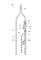
- FIG. 1 is a plan view of a bag-like container according to a first embodiment of the present invention
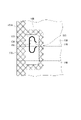
- FIG. FIG. 2 is a sectional view taken along line II-II of FIG. 1
- 2 is a cross-sectional view taken along line III-III of FIG. 1
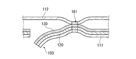
- FIG. FIG. 10 is a diagram for explaining the principle of breaking of the band-shaped base at the intersection with the joint region
- FIG. 10 is a diagram for explaining the principle of breaking of the band-shaped base at the intersection with the joint region
- FIG. 2 is an enlarged view of a surrounding seal portion of the bag-shaped container shown in FIG. 1; It is a figure which shows the manufacturing process of the bag-like container which concerns on the 1st Embodiment of this invention.
- FIG. 7 is an enlarged cross-sectional view showing a part of the manufacturing process shown in FIG. 6;
- FIG. FIG. 4 is a plan view of a bag-like container according to a second embodiment of the present invention;
- FIG. 9 is an enlarged view of a surrounding seal portion of the bag-shaped container shown in FIG. 8;
- FIG. 8 is a plan view of a bag-like container according to a third embodiment of the present invention;
- FIG. 11 is a cross-sectional view of the bag-like container shown in FIG. 10 taken along the line XI-XI;
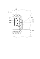
- FIG. 10 is a cross-sectional view of a bag-like container according to a fourth embodiment of the present invention;
- FIG. 11 is a plan view of a bag-like container according to a fifth embodiment of the present invention
- FIG. 14 is a cross-sectional view of the bag-like container shown in FIG. 13 taken along line XIV-XIV; It is a figure which shows the structural example of the film assembly which concerns on the 5th Embodiment of this invention.
- FIG. 16 is a diagram showing a manufacturing process of a bag-like container using the film assembly shown in FIG. 15;
- FIG. 1 is a plan view of a bag-like container according to the first embodiment of the present invention
- FIG. 2 is a cross-sectional view taken along line II-II of FIG. 1
- FIG. 3 is a cross-sectional view taken along line III-III of FIG. be.
- bag-like container 100 includes film 110 , tear strip 120 , strip base 130 , and zipper portion 140 .
- the film 110 is folded back at both side portions 101A and 101B of the bag-like container 100, and the portions facing each other are joined by the top seal portion 102, the bottom seal portion 103 and the back seal portion 104 to form a bag-like container body.
- the method of forming the container body with the film 110 is not particularly limited.
- the film 110 is folded only at one side portion 101A (or side portion 101B) of the bag-like container 100, and the opposite side portion is provided with a side seal. may form a part.
- the container body may be formed of two films by forming side seal portions on the side portions 101A and 101B.
- the bag-like container may be provided without forming the top seal portion 102 or the bottom seal portion 103, and the top seal portion or the bottom seal portion may be formed afterwards.
- a container including a container body other than a bag-shaped container body may be provided.
- the tear strip 120 and the strip base 130 are elongate members extending in the same direction and are interposed between the two surfaces of the film 110 forming the container body. These two surfaces are also referred to as first film 111 and second film 112 in the following description. As mentioned above, in the illustrated example the first film 111 and the second film 112 are formed by folding a single film, in other examples the first film 111 and the second film 112 may be formed by separate films. As shown in the cross-sectional views of FIGS. 2 and 3, the first film 111, the tear strip 120, the base strip 130 and the second film 111, 120 and the base strip 130 are interposed. 112 are stacked in this order. Note that these members may be stacked with other members interposed therebetween.
- the stacked members are not necessarily joined together except for the surrounding seal portion 160, which will be described later.
- the tear strip 120 is bonded to the first film 111 and the base strip 130 is bonded to the tear strip 120 and the first film 111, but the base strip 130 and the second film 112 are bonded together. and are not joined except for the surrounding seal portion 160 .
- the film 110 is, for example, a single layer or multilayer thermoplastic resin film.
- Thermoplastics are for example low density polyethylene (LDPE), linear low density polyethylene (LLDPE) or polypropylene (PP).
- PP is for example homopolypropylene (HPP), random polypropylene (RPP) or block polypropylene (BPP).
- biaxially oriented polypropylene (OPP), biaxially oriented polyethylene terephthalate (OPET) or biaxially oriented nylon (ONy) may be used for the front substrate.
- the resin that forms the film 110 may not necessarily be derived from fossil fuels, and may be, for example, an environmentally friendly bioplastic or a mixture of a fossil fuel-derived resin and a bioplastic.
- bioplastics for example, biopolyethylene and biopolypropylene can be suitably used.
- Bio-PET, bio-nylon, etc. can also be used as bio-plastics.
- Film 110 may include a layer of a metallic material such as aluminum or an inorganic material.
- the tear strip 120 and the band-shaped base 130 are formed, for example, by extrusion molding of a resin composition containing polyolefin resin.
- Polyolefin resins are, for example, LDPE, LLDPE or PP.
- PP is for example HPP, RPP or BPP.
- the resin forming the tear strip 120 and the base strip 130 may not necessarily be derived from fossil fuels, such as environmentally friendly bioplastics or mixtures of fossil fuel derived resins and bioplastics. There may be.
- bioplastics for example, biopolyethylene and biopolypropylene can be suitably used.
- the material of at least one of the tear strip 120 and/or the strip base 130 is optionally added with known additives such as stabilizers, antioxidants, lubricants, antistatic agents, or colorants. good too.
- the tear strip 120 and the band-shaped base 130 are formed of a combination of resins having low compatibility with each other.
- the tear strip 120 may be made of a polypropylene-based resin
- the band-shaped base portion 130 may be made of a low-density polyethylene-based resin.
- LLDPE/RPP LLDPE/RPP
- LDPE/HPP LLDPE/HPP
- LDPE/polystyrene PS
- LLDPE/PS RPP/PS
- HPP/PS LDPE/polyethylene terephthalate
- LLDPE/PET LLDPE/PET
- RPP/PET HPP/PET
- PS/PET LDPE/Nylon (Ny)
- At least a portion of LLDPE may be metallocene-based linear low-density polyethylene.
- the tear strip 120 and base strip 130 may be formed of bioplastics or a blend of fossil fuel-derived resins and bioplastics.
- Bio-polyethylene and bio-polypropylene can be suitably used as bioplastics.
- Bio-PET, bio-polystyrene, bio-nylon, etc. can also be used as bio-plastics.
- the zipper portion 140 includes a first base portion 141 formed following the band-shaped base portion 130 and a second base portion facing the first base portion 141 and joined to the first film 111. 142, and engagement portions 143A and 143B projecting from the first base portion 141 and the second base portion 142, respectively, and capable of engaging with each other.
- the zipper portion 140 is made of, for example, the same material as the band-shaped base portion 130 described above.
- the shape of the engaging portions 143A and 143B is not limited to the male-female type shown in the figure, and may be any known zipper engaging portion shape combining a claw shape, hook shape, knob shape, or the like. is possible.
- the engaging portion 143A is a female type and the engaging portion 143B is a female type, but the opposite is possible.
- the engagement portions need not be one pair, and one or more pairs of additional engagement portions, such as hooks 144A and 144B shown in phantom lines, may be provided.
- the resin forming the zipper portion 140 does not necessarily have to be derived from fossil fuels either.
- it may be an eco-friendly bioplastic or a mixture of fossil fuel-derived resin and bioplastic.
- bioplastics for example, biopolyethylene and biopolypropylene can be suitably used.
- Known additives such as stabilizers, antioxidants, lubricants, antistatic agents, or colorants may be added to the material of the zipper portion 140, if necessary.
- the tear strip 120 is gripped and pulled by the user from a tab 150 formed near one side 101A of the bag-like container 100, whereby the tear strip 120 is pulled.
- a strip 120 can tear the first film 111 to form an opening in the container body.
- a notch 121 may be formed through the first film 111 and the tear strip 120 at a position close to the side 101B of the bag-like container 100 opposite the tab 150 . Forming the cut 121 makes it easier to form the end of the tear. may not be formed.
- the container body can be resealed by engaging the engaging portions 143A and 143B with each other, and the container body can be reopened by releasing the engagement.
- the tab 150 and surround seal 160 are formed for the operation of forming an opening in the container body using the tear strip 120 as described above.
- tab 150 is formed by notch 151 penetrating first film 111 , tear strip 120 and base strip 130 at a position near one side 101 A of bag-like container 100 .
- the user can easily grasp and pull the tear strip 120 by pulling the tab 150 toward the first film 111 side.
- the notch 151 has a pot-shaped planar shape, the open portion corresponding to the mouth of the pot being oriented in the direction in which the opening is formed by the tear strip 120 .
- the planar shape of the cut 151 is not particularly limited, and the planar shape of the cut 151 in other examples may be, for example, C-shaped, U-shaped, or horseshoe-shaped.
- Surrounding seal 160 is the bonding area surrounding tab 150 and includes intersection 161 across tear strip 120 and strip base 130 .
- the first film 111, the tear strip 120, the strip base 130 and the second film 112 are joined together, for example by heat sealing or ultrasonic sealing.
- Tab 150 is formed in the non-bonded area adjacent to surround seal 160 , ie, the area where there is no bond between base strip 130 and second film 112 .
- the surrounding seal portion 160 may at least partially surround the tab 150 and does not necessarily have to surround the entire circumference of the tab 150 .
- the enclosing seal portion 160 has a U-shaped planar shape in which both ends are in contact with the side portions 101A of the bag-like container 100 on which the film 110 is folded, thereby covering three sides of the tab 150 except for the side portions 101A. Surrounding. In other examples, the surround seal 160 may surround the tab 150 with the top seal 102 or the side seals. Moreover, when the top seal portion is formed afterward, the entire periphery of the tab 150 does not have to be enclosed when the bag-like container is provided.
- the space formed between the first film 111 and the second film 112 in the non-bonded area including the tab 150 is the bounding area, which is the bonded area. It is spatially separated from other spaces in the container body across the seal portion 160 . Therefore, even if the tab 150 is formed by the cut 151 penetrating the first film 111, the container body can be kept sealed.
- the cut 151 forming the tab 150 only needs to penetrate at least the first film 111 and the tear strip 120, and may not penetrate the band-shaped base 130 due to processing error, for example. Even if the user grips only the first film 111 and the tear strip 120 with the tab 150, the tear strip 120 and the strip base 130 are interfacially delaminated, so opening is possible. Also, as long as the user does not grip the second film 112 together with the tear strip 120 with the tab 150, even if the cut 151 partially penetrates the second film 112 due to, for example, a processing error. good. As described above, the space in which the tab 150 is formed is separated from the other space in the container body by the enclosing seal portion 160, so even if the cut 151 partially penetrates the second film 112, the container body does not affect the sealing properties of the
- the intersection 161 of the surround seal 160 forms a bond area across the tear strip 120 and the base strip 130
- the tear strip 120 is used to create an opening in the container body by at least partially shaping the tab 150 side edge of the joining region at the intersection 161 so as not to be perpendicular to the longitudinal direction of the tear strip 120 .
- a smooth separation between the tear strip 120 and the strip base 130 can be obtained.
- the base strip 130 is torn longitudinally at the extension of the notch 151.
- the tearing strip 120 has a relatively high resistance to pulling because the strip base 130 is being torn, but by breaking the strip base 130 at the intersection 161 as shown in FIG. The leading edge can pull the tear strip 120 separated from the base strip 130 with relatively little resistance to tear the first film 111 and form an opening in the container body.
- the first film 111, the tear strip 120, the strip base 130 and the second film 112 are joined together at the intersection 161.
- the tension of tear strip 120 reaches intersection 161 as shown in FIG. A force acts to separate the two films 112 .
- the bond between the second film 112 and the strip base 130 is joined with a normal bond strength, whereas the tear strip 120 and the strip base 130 are made of a combination of less compatible resins as described above. , the bonding strength is relatively low. Therefore, at the intersection 161 , interfacial peeling occurs between the torn strip 120 and the base strip 130 instead of separation between the base strip 130 and the second film 112 by the above force.
- a portion of the band-shaped base 130 that has been pulled along with the tear strip 120 and the other portion of the band-shaped base 130 joined to the second film 112 are broken. .
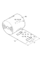
- FIG. 5 is an enlarged view of the enclosing seal portion of the bag-shaped container shown in FIG.
- at an intersection 161 of the surround seal portion 160 that intersects the tear strip 120 at least one protrusion 162 is formed on the tab 150 side edge of the bond area.
- the protruding portion 162 is a portion of the edge of the joint region that protrudes toward the tab 150 side.
- the protrusion 162 may protrude with respect to the edge of the bonding area when the protrusion 162 is not formed as in the illustrated example, or a recess may be formed at the edge of the bonding area.
- a protrusion 162 may protrude from the bottom of the recess.
- the protrusion 162 does not necessarily have to protrude with respect to the edge of the bonding area if the protrusion 162 were not formed. Also, in the illustrated example, a plurality of protrusions 162 form a continuous sawtooth shape, but the protrusions 162 may be formed discretely. At least one protrusion 162 may be formed to overlap the tear strip 120 , and more preferably, a plurality of protrusions 162 may be formed to overlap the tear strip 120 .
- the projecting portion 162 By forming the projecting portion 162 as described above, it becomes easier to break the band-shaped base portion 130 at the intersection portion 161 when the tearing strip 120 is pulled to form an opening in the container body. More specifically, when the tear strip 120 is pulled from the tab 150 side, the first film 111, the tear strip 120 and the strip base 130 that are pulled at the intersection 161 and the unstretched The force to separate from the second film 112 concentrates on the tip of the projecting portion 162 prior to other portions. By concentrating the force at the tip of the projection 162, the force is smaller than if the force were dispersed, for example, because the edge of the joining area is formed in a straight line perpendicular to the longitudinal direction of the tear strip 120. to break the base strip 130 and separate the tear strip 120 and the base strip 130 as shown in FIG. 4B.
- the opening strength of the bag-like container according to this embodiment that is, the maximum value of the force required when the tear strip is pulled to form the opening in the container body, is This is reduced compared to the case of forming an opening in a bag-like container in which no is formed.
- the opening strength of the bag-like container according to the present embodiment is preferably 95% or less, more preferably 90% or less. , more preferably 80% or less, particularly preferably 70% or less.
- the width W of the projections 162, i.e. the dimension of the individual projections 162 across the width of the tear strip 120, should be less than or equal to 100% of the width of the tear strip 120 for effective force concentration. is preferably 80% or less, more preferably 60% or less, and particularly preferably 45% or less. Assuming a general width of the tear strip 120 from the size of the finger of the user holding the tear strip 120, the width W of the protrusion 162 is preferably 3 mm or less. It is more preferably 2 mm or less, and even more preferably 1.3 mm or less.
- the width W of the protrusion 162 is preferably 0.3 mm or more, more preferably 0.5 mm or more, and more preferably 0.7 mm. It is more preferable that it is above.
- the width W is preferably 5% or more of the width of the tear strip 120, more preferably 10% or more, and 25% of the width of the tear strip 120. % or more is more preferable.
- the protrusion height H of the protrusions 162 that is, the height at which the individual protrusions 162 protrude from the concave portions or linear portions on both sides thereof in the planar shape should be 0. It is preferably 0.3 mm or more, more preferably 0.5 mm or more, and even more preferably 0.7 mm or more. In order not to make the surrounding seal portion 160 unnecessarily large, the protrusion height H of the protrusion 162 is preferably 5 mm or less, more preferably 2 mm or less, and more preferably 1.5 mm or less. preferable.
- the width R of the range in which the plurality of protrusions 162 are formed is , preferably equal to or greater than the width of the tear strip 120 .
- the mountain-shaped protruding portion as in the illustrated example is not necessarily formed. good too.
- protrusions such as trapezoidal, rectangular or arcuate may be formed.
- the shape of the tab 150 side edge of the joining region overlapping the tear strip 120 includes at least one concave portion or an oblique angle formed obliquely with respect to the longitudinal direction of the tear strip 120 . may contain parts.
- the tear line can be used.
- the bond area formed across the strip and strip base need not necessarily be a surround seal surrounding the tab.
- FIG. 6 is a diagram showing the manufacturing process of the bag-like container according to the first embodiment of the present invention.
- FIG. 7 is an enlarged cross-sectional view showing a part of the manufacturing process shown in FIG.
- manufacturing apparatus 600 includes elongate member joining means 610, tab forming means 620, cut forming means 630, back seal forming means 640, and top/bottom seal forming means 650. . If the bag-like container is not provided with the cut 121 described above, the cut forming means 630 is omitted. In the manufacturing apparatus 600, the film 110 pulled out from a roll (not shown) or the like is intermittently transported and processed in the above sections. Each part will be further described below.
- the long member joining means 610 joins the long member consisting of the tear strip 120, the band-shaped base portion 130 and the zipper portion 140 along the width direction of the film 110 conveyed in the longitudinal direction.
- the tear strip 120, base strip 130 and zipper portion 140 may be formed as a unitary elongated member, such as by extrusion (including co-extrusion).
- tear strip 120 may be molded separately from base strip 130 and zipper portion 140 and joined to film 110 by separate joining means.
- the long member is joined to the portion that will become the first film 111 after a folding process as described later.
- the long member joining means 610 includes a feeder 611 and seal bars 612A and 612B.
- a feeder 611 feeds a long member of a predetermined length and arranges it at a predetermined position on the film 110 .
- the feeder 611 may include a cutter (not shown) that cuts the elongate member into a predetermined length.
- the seal bars 612A, 612B sandwich the film 110 together with the elongated members arranged thereon, and are bonded to the film 110 by, for example, heat sealing or ultrasonic sealing.
- an adhesive may be applied in advance between the long member and the film 110, and the seal bars 612A and 612B may sandwich and press the laminated film 110 and the long member to join them. .
- the tab forming means 620 forms tabs by means of cuts 151 penetrating the film 110 and the long member joined to the film 110 .
- tab forming means 620 includes a cutter 621 and a pedestal 622 .
- Cutter 621 has a planar shape corresponding to cut 151 .
- the long member is joined to the portion that will become the first film 111, but since the film 110 has not yet been folded back at this stage, the cut 151 penetrating the film 110 and the long member is the bag.
- the second film 112 is not penetrated after the container 100 is completed.
- the incision forming means 630 forms incisions 121 in the film 110 and the long members joined to the film 110 .
- the cut forming means 630 includes a cutter 631 and a cradle 632 . Since in this embodiment the cut 121 penetrates the film 110 and the tear strip 120 and not the strip base 130, the cut depth of the cutter 631 corresponds to the combined thickness of the film 110 and the tear strip 120. adjusted to quantity.
- the sealing of the container body in the vicinity of the cut 121 may be improved by pressing the region including the cut 121 after the cut 121 is formed.
- the back seal forming means 640 rolls both sides of the film 110 in the width direction into a tubular shape to form the back seal portion 104, thereby forming the general shape of the container body composed of the first film 111 and the second film 112.
- the back seal forming means 640 includes a winding core 641 , a conveying belt 642 and a sealing device 643 .
- the film 110 is transported from above to below by a transport belt 642 while being wound around a core 641 .
- the cylindrically wound film 110 is folded back on both sides in the width direction corresponding to the side portions 101A and 101B of the bag-like container 100, thereby forming the first film 111 and the second film 112 as described above. be done.
- the sealing device 643 forms the back seal portion 104 by joining both ends of the wound film 110 in the width direction, for example, by heat sealing or ultrasonic sealing.
- the top/bottom seal forming means 650 forms the top seal portion 102 and the bottom seal portion 103 on the film 110 folded on both sides in the width direction, and cuts the film 110 in the width direction to form the bag-like container 100. do. Additionally, the top/bottom seal forming means 650 forms the surround seal 160 as described above. As shown in the enlarged cross-sectional view of FIG. including.
- the seal bars 651A and 651B are opposed to each other on both upper and lower sides with the cutter 652 interposed therebetween, and the opposed portions form the top seal portion 102 and the bottom seal portion 103 by heat sealing or ultrasonic sealing, for example.
- the cutter 652 and the pedestal 653 are moved together with the seal bars 651A and 651B to move toward and away from each other, and move the film 110 in the width direction between the top seal portion 102 and the bottom seal portion 103 formed by the seal bars 651A and 651B. disconnect.
- the winding core 641 of the back seal forming means 640 is hollow, and the filling device 601 is inserted inside from above.
- the filling device 601 discharges the contents in synchronization with the film 110 being sandwiched between the seal bars 651A and 651B in the top/bottom seal forming means 650 .
- the space formed above the bottom seal portion 103 of the bag-like container 100 is filled with the content.
- the sealing devices 654A, 654B sandwich the film 110 in synchronism with the sealing bars 651A, 651B to form the enclosing sealed portion 160 by heat sealing or ultrasonic sealing, for example.
- the seal bars of the seal devices 654A, 654B have a planar shape corresponding to the surround seal portion 160 as shown in FIG. 5, for example.
- the seal bar has a U-shaped planar shape surrounding three sides of a predetermined region where the tab is formed by the notch 151, and the inner edge of at least one side of the planar shape includes at least one protrusion.
- the seal bar may have a non-U-shaped shape including the portion outside the film 110, for example, a substantially rectangular planar shape surrounding the predetermined area on all sides.
- the bag-like container 100 can be manufactured by the steps described above. Note that the above process is an example, and various modifications are possible.
- tab forming means 620 and notch forming means 630 may be arranged in the reverse order of the example above.
- tab forming means 620 and incision forming means 630 may be integrated so that incision 151 and incision 121 are formed substantially simultaneously.
- the seal bars 651A and 651B included in the top/bottom seal forming means 650 are separated from the cutter 652 and the pedestal 653, and after the top seal portion 102 and the bottom seal portion 103 are formed, the film is 110 may be cut across the width.
- the sealing devices 654A and 654B may form the surrounding seal portion 160 before the top seal portion 102 and the bottom seal portion 103 are formed by the seal bars 651A and 651B.
- the sealing devices 654A and 654B may arrange the sealing devices 654A and 654B above the seal bars 651A and 651B and forming the surrounding seal portion 160 before the bottom seal portion 103 positioned at the bottom of the bag-like container 100 is formed, the bottom Contents filled in synchronization with the formation of the seal portion 103 can be prevented from adhering to the inner region of the enclosing seal portion 160 .
- the bag-like container 100 does not necessarily have to be manufactured while being filled with the contents. may
- the tab forming means 620 may be arranged after the sealing devices 654A, 654B forming the enclosing seal portion 160.
- the cutter 621 is arranged on the first film 111 side
- the pedestal 622 is arranged on the second film 112 side.
- the cut 151 forming the tab does not penetrate completely through the second film 112, so the cut depth of the cutter 621 corresponds to the combined thickness of the first film 111, the tear strip 120 and the base strip 130. adjusted to quantity. Forming the cut 151 after the surrounding seal portion 160 minimizes deformation of the cut due to heat shrinkage of the film, for example, when forming a heat seal or an ultrasonic seal.
- the bag-like container according to another embodiment of the present embodiment can be manufactured using other known processes for manufacturing the bag-like container 100 according to the first embodiment as described above. It can be manufactured by combining the manufacturing process of the bag-like container, or by replacing part of the manufacturing process of the bag-like container 100 with the manufacturing process of another bag-like container. Therefore, the description of the manufacturing process is omitted in the description of other embodiments below.
- FIG. 8 is a plan view of a bag-like container according to a second embodiment of the present invention
- FIG. 9 is an enlarged view of the enclosing seal portion of the bag-like container shown in FIG.
- the bag-like container 200 does not have a rear seal portion, but instead has a side seal portion 205 formed on the side portion 101A.
- the surrounding seal portions 160 together with the side seal portions 205 form joint regions surrounding the tab 150 on all sides. Therefore, in the present embodiment, the seal bar forming the surrounding seal portion 160 includes a substantially rectangular planar shape that surrounds the predetermined region in which the tab is formed by the cuts 151, and has an inner side on at least one side of the planar shape.
- the edge includes at least one protrusion.
- the seal bar is formed integrally with the seal bar forming the side seal portion 205 . Since the configuration of the present embodiment is the same as that of the above-described first embodiment except for the points described above, redundant detailed description will be omitted. The modifications described for the first embodiment are similarly applicable to this embodiment.
- FIG. 10 is a plan view of a bag-like container according to a third embodiment of the present invention
- FIG. 11 is a cross-sectional view of the bag-like container shown in FIG. 10 taken along line XI-XI.
- the bag-like container 300 is a so-called gusset bag
- the side portions 101A and 101B of the bag-like container 300 form portions 311A and 311B in which the film 110 is folded inside the container body.
- the surround seal 160 joins together the first film 111, the tear strip 120, the strip base 130 and the film forming the folded portion 311A.
- the film forming the folded portion 311A corresponds to the second film 112 in the first embodiment.
- a portion 312 is formed by folding a film different from the film 110 inside the container body.
- the configuration of the gusset bag is not limited to the above example, and various known techniques can be used.
- the folded side portion may be formed of a film different from film 110 .
- side seal portions may be formed instead of the rear seal.
- the configuration of this embodiment is the same as that of the above-described first embodiment, so redundant detailed description will be omitted.
- the modifications described for the first embodiment are similarly applicable to this embodiment.
- FIG. 12 is a cross-sectional view of a bag-like container according to a fourth embodiment of the invention.
- FIG. 12 is a cross-sectional view of a portion corresponding to line III--III shown in FIG.
- the bag-like container 400 does not include a zipper portion.
- the cross-section of base strip 430 includes a recess 432 and protrusions 431 and 433 on either side thereof, with tear strip 120 positioned in recess 432 .
- a slit 434 is formed in the concave portion 432 , and after the tearing strip 120 cuts the first film 111 while interfacially peeling from the band-shaped base portion 430 to form an opening in the container body, the opening is formed in the container body through the slit 434 .
- the first film 111 , the tear strip 120 , the recess 432 of the base strip 430 and the second film 112 are joined together at the enclosing seal 160 . Therefore, the edge of the tab 150 at the intersection of the surrounding seal portion 160 with the tear strip 120 is at least partially shaped so that the tear strip 120 is not perpendicular to the longitudinal direction of the tear strip 120 .
- the configuration in which no zipper portion is provided as in the fourth embodiment is adopted when resealing and resealing of the bag-like container after forming the opening are not required.
- the configuration in such a case is not limited to the example of the fourth embodiment, and may be, for example, the configuration of the first embodiment shown in cross section in FIG. may
- FIG. 13 is a plan view of a bag-like container according to a fifth embodiment of the present invention
- FIG. 14 is a cross-sectional view of the bag-like container shown in FIG. 13 taken along line XIV-XIV.
- bag-like container 500 includes film 110 , tear strip 120 , strip base 130 , zipper portion 140 and protective member 170 .
- a tab 150 is formed near one side portion 101A of the bag-like container 100, that is, near one longitudinal end portion of the elongated member including the tear strip 120, the band-shaped base portion 130 and the zipper portion 140. be.
- a protective member 170 joined to the area covering the tab 150 is also included in the elongated member.
- the protective member 170 is joined from the band-shaped base 130 side to the area covering the tab 150 formed by the first film 111 , the tear strip 120 and the cut 151 passing through the band-shaped base 130 .
- protective member 170 extends at least partially beyond base strip 130 and may also be bonded to first film 111 .
- the space leading to the notch of the tab 150 is sealed inside the container body by the protective member 170, and the tear strip 120 can be used to improve the sealing performance of the bag-like container 500 before it is opened.
- the protection member 170 is made of the same material as the film 110 described above, for example. Although it is possible to select different materials for the protective member 170 and the film 110 from among the materials described above, it is more preferable to select the same material for the protective member 170 and the film 110 .
- the tear strip 120 is used to open the bag-like container 500 by arranging the protective member 172 so as to cover the region in which the notch 121 is formed on the opposite side of the tab 150 from the inside of the container body.
- the sealing performance of the bag-like container 500 before being sealed can be improved.
- the cut 121 may be formed through the first film 111 and the tear strip 120 but not through the base strip 130 . In this case, the space leading to the cut 121 does not reach the inside of the container body, so the protective member 172 may not be arranged. Also, as described in the first embodiment, the notch 121 does not necessarily have to be formed.
- the protective member 170 is joined to the band-shaped base 130 at the surrounding seal portion 560 .
- Surrounding seal 560 is the bonding area surrounding tab 150 and includes intersections across tear strip 120 and strip base 130 similar to the surrounding seals described in the first embodiment above.
- the first film 111, the tear strip 120, the base strip 130 and the protective member 170 are joined together, for example by heat sealing or ultrasonic sealing.
- Tab 150 is formed in a non-bonded area adjacent surround seal 560 , ie, an area where there is no bond between base strip 130 and protective member 170 .
- the container body By surrounding the tab 150 with the surrounding seal portion 560, the space that communicates with the outside through the cut 151 of the tab 150 is separated from the surrounding seal portion 560 and the protective member 170, which are joining areas, from other spaces in the container body. Spatially separated. Therefore, even if the tab 150 is formed by the cut 151 penetrating the first film 111, the container body can be kept sealed.
- the tab 150 side edge of the surround seal 560 is at least partially non-perpendicular to the longitudinal direction of the tear strip 120.
- the intersecting portion of the surrounding seal portion 560 is configured in the same manner as the example described with reference to FIG. 5 for the first embodiment, for example.
- the tear strip 120 and the band-shaped base portion 130 can be smoothly separated from each other. Since the configuration of the present embodiment is the same as that of the above-described first embodiment except for the points described above, redundant detailed description will be omitted.
- the modifications described for the first embodiment are similarly applicable to this embodiment. It is also possible to combine the second, third and fourth embodiments with this embodiment.
- FIG. 15 is a diagram showing a configuration example of a film assembly according to the fifth embodiment of the invention.
- the film assembly 550 includes the film 110 before being folded back at the side portions 101A and 101B, and the film 110 wound on the roll on one side of the film 110 so as to be separated from each other along the longitudinal direction. and at least two elongated members attached to each other.
- the elongated member includes a tear strip 120 , a strip base 130 , a zipper portion 140 and a protective member 170 . Tabs are formed in the elongate member by notches 151 .
- a surround seal 560 (see FIG. 14), which is the bonding area where the film 110, tear strip 120, strip base 130 and protective member 170 are bonded together.
- the width L1 of the film is greater than twice the length L2 of the elongate member.
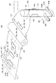
- FIG. 16 is a diagram showing the manufacturing process of a bag-like container using the film assembly shown in FIG.
- the film assembly 550 unwound from the roll is attached with elongated members including the tear strip 120, base strip 130, zipper portion 140 and protective member 170, thus permitting bag-like container manufacture. Sometimes the step of attaching them is not required.
- the film assembly 550 is formed into a bag-like container by back seal forming means 640 and top/bottom seal forming means 650 as in the example shown in FIG. In this embodiment, the film assembly 550 already has the surrounding seal 560 formed thereon, so the top/bottom seal forming means 650 need not include a sealing device for forming the surrounding seal. .
- the manufacturing process of the bag-like container according to the present embodiment is not limited to this example. good too.
- a step of joining the protective member 170 to the elongated member with the enclosing seal portion 560 is performed after the tab is formed in the elongated member by the cut 151 .
- Example 1 in which a protrusion is formed on the tab side edge at the intersection where the torn strip of the surrounding seal portion intersects, and the tab side edge of the intersection is formed in a straight line.
- the time from the start of pulling by pinching the tab until the tearing of the film by the tear strip passed through the intersection of the enclosing seal portion The maximum value of tensile strength (maximum tensile strength at opening) was measured.
- the tensile strength was measured at a tensile speed of 300 mm/min using a "digital force gauge" manufactured by Imada.
- Example 1 the tear strips were made of random polypropylene and the base strips were made of low density polyethylene. From the results of Examples and Comparative Examples shown in Table 1, it was shown that the maximum value of tensile strength at opening was greatly reduced by forming protrusions on the edges of the joint regions.
Landscapes
- Engineering & Computer Science (AREA)
- Mechanical Engineering (AREA)
- Chemical & Material Sciences (AREA)
- Composite Materials (AREA)
- Bag Frames (AREA)
- Making Paper Articles (AREA)
Priority Applications (5)
| Application Number | Priority Date | Filing Date | Title |
|---|---|---|---|
| JP2023536723A JP7850724B2 (ja) | 2021-07-20 | 2022-07-14 | 容器、容器の製造方法、容器の製造装置、シールバーおよびフィルム組立体 |
| KR1020247001713A KR20240037236A (ko) | 2021-07-20 | 2022-07-14 | 용기, 용기의 제조 방법, 용기의 제조 장치, 시일 바 및 필름 조립체 |
| CN202280050215.7A CN117693478A (zh) | 2021-07-20 | 2022-07-14 | 容器、容器的制造方法、容器的制造装置、密封条以及膜组装体 |
| US18/580,307 US20240327091A1 (en) | 2021-07-20 | 2022-07-14 | Container, method for manufacturing container, device for manufacturing container, seal bar, and film assembly |
| EP22845859.2A EP4375212A4 (en) | 2021-07-20 | 2022-07-14 | CONTAINER, METHOD FOR MANUFACTURING A CONTAINER, DEVICE FOR MANUFACTURING A CONTAINER, SEALING JAW AND FILM ASSEMBLY |
Applications Claiming Priority (2)
| Application Number | Priority Date | Filing Date | Title |
|---|---|---|---|
| JP2021119506 | 2021-07-20 | ||
| JP2021-119506 | 2021-07-20 |
Publications (1)
| Publication Number | Publication Date |
|---|---|
| WO2023002925A1 true WO2023002925A1 (ja) | 2023-01-26 |
Family
ID=84979269
Family Applications (1)
| Application Number | Title | Priority Date | Filing Date |
|---|---|---|---|
| PCT/JP2022/027770 Ceased WO2023002925A1 (ja) | 2021-07-20 | 2022-07-14 | 容器、容器の製造方法、容器の製造装置、シールバーおよびフィルム組立体 |
Country Status (7)
| Country | Link |
|---|---|
| US (1) | US20240327091A1 (https=) |
| EP (1) | EP4375212A4 (https=) |
| JP (1) | JP7850724B2 (https=) |
| KR (1) | KR20240037236A (https=) |
| CN (1) | CN117693478A (https=) |
| TW (1) | TW202323022A (https=) |
| WO (1) | WO2023002925A1 (https=) |
Cited By (1)
| Publication number | Priority date | Publication date | Assignee | Title |
|---|---|---|---|---|
| EP4520677A1 (en) * | 2023-09-07 | 2025-03-12 | Illinois Tool Works Inc. | Zipper assembly with separate tear strip and method of manufacturing the same |
Citations (5)
| Publication number | Priority date | Publication date | Assignee | Title |
|---|---|---|---|---|
| JP2005263300A (ja) * | 2004-03-19 | 2005-09-29 | Idemitsu Unitech Co Ltd | ファスナー付き包装袋、その製造方法、並びにファスナー取付装置 |
| WO2006112448A1 (ja) * | 2005-04-18 | 2006-10-26 | Idemitsu Unitech Co., Ltd. | チャックテープ付き袋の製造装置、製造方法 |
| JP2018188196A (ja) * | 2017-05-08 | 2018-11-29 | 出光ユニテック株式会社 | 袋体、フィルム体、及び袋体の製造方法 |
| JP2019051963A (ja) | 2017-09-14 | 2019-04-04 | 出光ユニテック株式会社 | 袋体、袋体の製造方法および製造装置 |
| JP6714957B1 (ja) * | 2019-02-19 | 2020-07-01 | 朋和産業株式会社 | 包装用シートの製造方法及び包装用シート原反の製造方法 |
Family Cites Families (5)
| Publication number | Priority date | Publication date | Assignee | Title |
|---|---|---|---|---|
| JPS6013661A (ja) * | 1983-06-24 | 1985-01-24 | 株式会社平野屋物産 | 合成樹脂袋のノツチ部構造 |
| JP3410142B2 (ja) * | 1993-03-30 | 2003-05-26 | 株式会社平野屋物産 | 開封容易とした自立可能な合成樹脂製袋 |
| JP4874742B2 (ja) * | 2006-08-21 | 2012-02-15 | 出光ユニテック株式会社 | カットテープ付きチャックテープ、その製造方法、およびチャックテープ付き包装袋 |
| JP6314444B2 (ja) * | 2013-11-26 | 2018-04-25 | 凸版印刷株式会社 | 背貼り包装袋 |
| CN108024600B (zh) * | 2015-09-14 | 2023-12-01 | 出光统一科技株式会社 | 带有卡扣带的袋体、袋体、袋体的制造方法及袋体的制造装置 |
-
2022
- 2022-07-14 EP EP22845859.2A patent/EP4375212A4/en active Pending
- 2022-07-14 JP JP2023536723A patent/JP7850724B2/ja active Active
- 2022-07-14 WO PCT/JP2022/027770 patent/WO2023002925A1/ja not_active Ceased
- 2022-07-14 CN CN202280050215.7A patent/CN117693478A/zh active Pending
- 2022-07-14 US US18/580,307 patent/US20240327091A1/en active Pending
- 2022-07-14 KR KR1020247001713A patent/KR20240037236A/ko active Pending
- 2022-07-20 TW TW111127173A patent/TW202323022A/zh unknown
Patent Citations (5)
| Publication number | Priority date | Publication date | Assignee | Title |
|---|---|---|---|---|
| JP2005263300A (ja) * | 2004-03-19 | 2005-09-29 | Idemitsu Unitech Co Ltd | ファスナー付き包装袋、その製造方法、並びにファスナー取付装置 |
| WO2006112448A1 (ja) * | 2005-04-18 | 2006-10-26 | Idemitsu Unitech Co., Ltd. | チャックテープ付き袋の製造装置、製造方法 |
| JP2018188196A (ja) * | 2017-05-08 | 2018-11-29 | 出光ユニテック株式会社 | 袋体、フィルム体、及び袋体の製造方法 |
| JP2019051963A (ja) | 2017-09-14 | 2019-04-04 | 出光ユニテック株式会社 | 袋体、袋体の製造方法および製造装置 |
| JP6714957B1 (ja) * | 2019-02-19 | 2020-07-01 | 朋和産業株式会社 | 包装用シートの製造方法及び包装用シート原反の製造方法 |
Non-Patent Citations (1)
| Title |
|---|
| See also references of EP4375212A4 |
Cited By (1)
| Publication number | Priority date | Publication date | Assignee | Title |
|---|---|---|---|---|
| EP4520677A1 (en) * | 2023-09-07 | 2025-03-12 | Illinois Tool Works Inc. | Zipper assembly with separate tear strip and method of manufacturing the same |
Also Published As
| Publication number | Publication date |
|---|---|
| JP7850724B2 (ja) | 2026-04-23 |
| CN117693478A (zh) | 2024-03-12 |
| KR20240037236A (ko) | 2024-03-21 |
| JPWO2023002925A1 (https=) | 2023-01-26 |
| TW202323022A (zh) | 2023-06-16 |
| EP4375212A1 (en) | 2024-05-29 |
| US20240327091A1 (en) | 2024-10-03 |
| EP4375212A4 (en) | 2025-09-24 |
Similar Documents
| Publication | Publication Date | Title |
|---|---|---|
| KR101175960B1 (ko) | 척 테이프가 부착된 주머니 | |
| TWI518008B (zh) | Easy to tear the folder chain, and with easy to tear the folder with the bag | |
| CN108024600A (zh) | 带有卡扣带的袋体、袋体、袋体的制造方法及袋体的制造装置 | |
| JP7098032B2 (ja) | 袋体、袋体の製造方法および製造装置 | |
| JPWO2003055761A1 (ja) | 易開封性包装袋 | |
| EP1325872B1 (en) | Fastener bag and fastener device | |
| TWI742121B (zh) | 帶及袋體 | |
| JP2014114035A (ja) | ジッパーテープ、ジッパーテープ付包材およびジッパーテープ付被装着物 | |
| US20070116388A1 (en) | Fastener bag and fastening device | |
| WO2023002925A1 (ja) | 容器、容器の製造方法、容器の製造装置、シールバーおよびフィルム組立体 | |
| JP2014113263A (ja) | ジッパーテープ、ジッパーテープ付包材およびジッパーテープ付被装着物 | |
| JP7612414B2 (ja) | 食品包装体 | |
| JP2022031066A (ja) | チャック付き包装袋 | |
| JP6495362B2 (ja) | テープ及び袋体 | |
| JP3251409U (ja) | 包装袋 | |
| JP2018062350A (ja) | テープ挿入型易開封ガゼット袋 | |
| JP2023082388A (ja) | 再封機能付き包装体 |
Legal Events
| Date | Code | Title | Description |
|---|---|---|---|
| 121 | Ep: the epo has been informed by wipo that ep was designated in this application |
Ref document number: 22845859 Country of ref document: EP Kind code of ref document: A1 |
|
| WWE | Wipo information: entry into national phase |
Ref document number: 2023536723 Country of ref document: JP |
|
| WWE | Wipo information: entry into national phase |
Ref document number: 202280050215.7 Country of ref document: CN |
|
| WWE | Wipo information: entry into national phase |
Ref document number: 18580307 Country of ref document: US |
|
| WWE | Wipo information: entry into national phase |
Ref document number: 2401000406 Country of ref document: TH |
|
| WWE | Wipo information: entry into national phase |
Ref document number: 2022845859 Country of ref document: EP |
|
| NENP | Non-entry into the national phase |
Ref country code: DE |
|
| ENP | Entry into the national phase |
Ref document number: 2022845859 Country of ref document: EP Effective date: 20240220 |